journal of materials chemistry c - sustceee.sustc.edu.cn/p/liuyanjun/all...
TRANSCRIPT
3552 | J. Mater. Chem. C, 2015, 3, 3552--3558 This journal is©The Royal Society of Chemistry 2015
Cite this: J.Mater. Chem. C, 2015,
3, 3552
The development of a wideband andangle-insensitive metamaterial filter withextraordinary infrared transmission formicro-thermophotovoltaics
D. Y. Jiang,a W. M. Yang,*a Y. J. Liu,b H. L. Liuc and J. H. Teng*b
Since the performance of the micro-thermophotovoltaic (TPV) system is significantly limited by the
mismatch between the radiation spectrum and the photovoltaic (PV) bandgap, for the first time, a
wideband and angle-insensitive metamaterial filter was developed and optimized to address this issue.
The developed filter was placed between the reactor and the PV cell and it was able to effectively
transmit the valuable photons for power generation and reflect the worthless energy, thus offering great
potential to improve the performance of the micro-TPV system. In particular, the filter is applicable for
the entire near infrared wavelength range and exhibits extraordinary transmission. For the working
wavelength applied in this paper, the obtained peak transmission coefficient from experiments is up to
88.3%. Furthermore, the efficiency of the micro-TPV system is also predicted to be enhanced more than
twice with the metamaterial filter applied. Both the experimental and theoretical results show that the
incorporation of the metamaterial filter with low bandgap PV cells can be a promising approach to
improve the efficiency of the existing micro-TPV system.
Introduction
The combustion-driven micro-TPV system has attracted muchattention for power generation in portable devices due to itssuperior energy density compared to the chemical batteries.1–3
A high performance filter is one of the key components in sucha system, which transmits the photons with energy greater thanthe bandgap of the PV diodes as well as reflects the photonswith energy not sufficient to generate charge carriers in the PVcells.4,5 In the past decade, both selective emitters6,7 andinfrared filters8,9 have been developed to reshape the radiationspectrum based on rare-earth oxides,10,11 photonic crystals12–14
and metamaterials.15,16 However, the reported selective emit-ters and filters still face the challenges of material availability,efficient spectral control in the long wavelength range,17–19
thermal stability20,21 and angle independency.22,23 The extra-ordinary optical transmission (EOT)24 phenomenon has beenobserved in the coaxial ring array,25 which is mainly due to thecylindrical surface plasmon (CSP), planar surface plasmon
(PSP) resonances26–28 and constructive interference. Besides,the optical response of the coaxial ring array is also insensitiveto the incidence angle.29 Hence, these two features make thecoaxial ring array a perfect candidate for high-efficiency spectralcontrol in the optical wavelength range. Here, we demonstratethe suitability of the similar extraordinary transmission pheno-menon and other superior features of the coaxial ring arraystructure in the infrared region and its further application inthe micro-TPV system. In addition, the energy transfer processof the micro-TPV system with the coaxial ring array filterapplied is also predicted in detail.
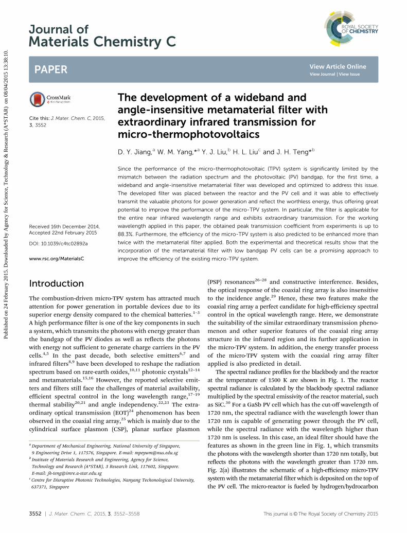
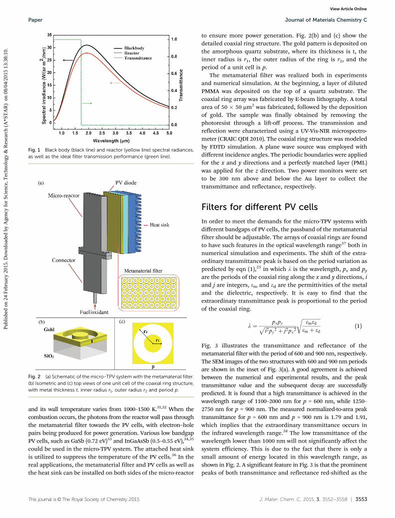
The spectral radiance profiles for the blackbody and the reactorat the temperature of 1500 K are shown in Fig. 1. The reactorspectral radiance is calculated by the blackbody spectral radiancemultiplied by the spectral emissivity of the reactor material, suchas SiC.30 For a GaSb PV cell which has the cut-off wavelength of1720 nm, the spectral radiance with the wavelength lower than1720 nm is capable of generating power through the PV cell,while the spectral radiance with the wavelength higher than1720 nm is useless. In this case, an ideal filter should have thefeatures as shown in the green line in Fig. 1, which transmitsthe photons with the wavelength shorter than 1720 nm totally, butreflects the photons with the wavelength greater than 1720 nm.Fig. 2(a) illustrates the schematic of a high-efficiency micro-TPVsystem with the metamaterial filter which is deposited on the top ofthe PV cell. The micro-reactor is fueled by hydrogen/hydrocarbon
a Department of Mechanical Engineering, National University of Singapore,
9 Engineering Drive 1, 117576, Singapore. E-mail: [email protected] Institute of Materials Research and Engineering, Agency for Science,
Technology and Research (A*STAR), 3 Research Link, 117602, Singapore.
E-mail: [email protected] Centre for Disruptive Photonic Technologies, Nanyang Techonological University,
637371, Singapore
Received 16th December 2014,Accepted 22nd February 2015
DOI: 10.1039/c4tc02892a
www.rsc.org/MaterialsC
Journal ofMaterials Chemistry C
PAPER
Publ
ishe
d on
24
Febr
uary
201
5. D
ownl
oade
d by
Age
ncy
for
Scie
nce,
Tec
hnol
ogy
& R
esea
rch
(A*S
TA
R)
on
08/0
4/20
15 1
3:38
:10.
View Article OnlineView Journal | View Issue
This journal is©The Royal Society of Chemistry 2015 J. Mater. Chem. C, 2015, 3, 3552--3558 | 3553
and its wall temperature varies from 1000–1500 K.31,32 When thecombustion occurs, the photons from the reactor wall pass throughthe metamaterial filter towards the PV cells, with electron–holepairs being produced for power generation. Various low bandgapPV cells, such as GaSb (0.72 eV)33 and InGaAsSb (0.5–0.55 eV),34,35
could be used in the micro-TPV system. The attached heat sinkis utilized to suppress the temperature of the PV cells.36 In thereal applications, the metamaterial filter and PV cells as well asthe heat sink can be installed on both sides of the micro-reactor
to ensure more power generation. Fig. 2(b) and (c) show thedetailed coaxial ring structure. The gold pattern is deposited onthe amorphous quartz substrate, where its thickness is t, theinner radius is r1, the outer radius of the ring is r2, and theperiod of a unit cell is p.
The metamaterial filter was realized both in experimentsand numerical simulation. At the beginning, a layer of dilutedPMMA was deposited on the top of a quartz substrate. Thecoaxial ring array was fabricated by E-beam lithography. A totalarea of 50 � 50 mm2 was fabricated, followed by the depositionof gold. The sample was finally obtained by removing thephotoresist through a lift-off process. The transmission andreflection were characterized using a UV-Vis-NIR microspectro-meter (CRAIC QDI 2010). The coaxial ring structure was modeledby FDTD simulation. A plane wave source was employed withdifferent incidence angles. The periodic boundaries were appliedfor the x and y directions and a perfectly matched layer (PML)was applied for the z direction. Two power monitors were setto be 300 nm above and below the Au layer to collect thetransmittance and reflectance, respectively.
Filters for different PV cells
In order to meet the demands for the micro-TPV systems withdifferent bandgaps of PV cells, the passband of the metamaterialfilter should be adjustable. The arrays of coaxial rings are foundto have such features in the optical wavelength range37 both innumerical simulation and experiments. The shift of the extra-ordinary transmittance peak is based on the period variation aspredicted by eqn (1),25 in which l is the wavelength, px and py
are the periods of the coaxial ring along the x and y directions, iand j are integers, em and ed are the permittivities of the metaland the dielectric, respectively. It is easy to find that theextraordinary transmittance peak is proportional to the periodof the coaxial ring.
l ¼ pxpyffiffiffiffiffiffiffiffiffiffiffiffiffiffiffiffiffiffiffiffiffiffiffiffiffiffii2py2 þ j2px2
pffiffiffiffiffiffiffiffiffiffiffiffiffiffiffiemed
em þ ed
r(1)
Fig. 3 illustrates the transmittance and reflectance of themetamaterial filter with the period of 600 and 900 nm, respectively.The SEM images of the two structures with 600 and 900 nm periodsare shown in the inset of Fig. 3(a). A good agreement is achievedbetween the numerical and experimental results, and the peaktransmittance value and the subsequent decay are successfullypredicted. It is found that a high transmittance is achieved in thewavelength range of 1100–2000 nm for p = 600 nm, while 1250–2750 nm for p = 900 nm. The measured normalized-to-area peaktransmittance for p = 600 nm and p = 900 nm is 1.79 and 1.91,which implies that the extraordinary transmittance occurs inthe infrared wavelength range.38 The low transmittance of thewavelength lower than 1000 nm will not significantly affect thesystem efficiency. This is due to the fact that there is only asmall amount of energy located in this wavelength range, asshown in Fig. 2. A significant feature in Fig. 3 is that the prominentpeaks of both transmittance and reflectance red-shifted as the
Fig. 1 Black body (black line) and reactor (yellow line) spectral radiances,as well as the ideal filter transmission performance (green line).
Fig. 2 (a) Schematic of the micro-TPV system with the metamaterial filter.(b) Isometric and (c) top views of one unit cell of the coaxial ring structure,with metal thickness t, inner radius r1, outer radius r2 and period p.
Paper Journal of Materials Chemistry C
Publ
ishe
d on
24
Febr
uary
201
5. D
ownl
oade
d by
Age
ncy
for
Scie
nce,
Tec
hnol
ogy
& R
esea
rch
(A*S
TA
R)
on
08/0
4/20
15 1
3:38
:10.
View Article Online

3554 | J. Mater. Chem. C, 2015, 3, 3552--3558 This journal is©The Royal Society of Chemistry 2015
period increased from 600 to 900 nm. It should be noted thatthe cut-off wavelength of the filter with p = 600 nm is 2400 nm,which can match the cut-off wavelength of the InGaAsSb PVcells (2345 nm) very well. For the PV cells such as InAsSbP39
with even lower energy bandgaps of 0.45–0.48 eV, the meta-material filter with larger periods could be employed.
Besides, it is also found that the transmission peak could be red-shifted by decreasing the ring size in the optical wavelengthrange.27,37 This phenomenon could also be observed in the infraredwavelength range. Fig. 4 shows two designs, which have the identicalmetal thickness t, outer diameter of the ring r2 and period p, but adifferent inner diameter of the ring r1. It is found that the designwith a larger r1 value indicating a lower gap size has a red-shiftedtransmittance profile in comparison with the design with a lowerr1 value. This might be attributed to the enhancements at longwavelengths to TE1 guided modes of individual coaxial rings.40
Wideband and angle-insensitive filters
To meet the demand for the micro-TPV system, the metamaterialfilter should also possess a wide passband, i.e., maintain a high
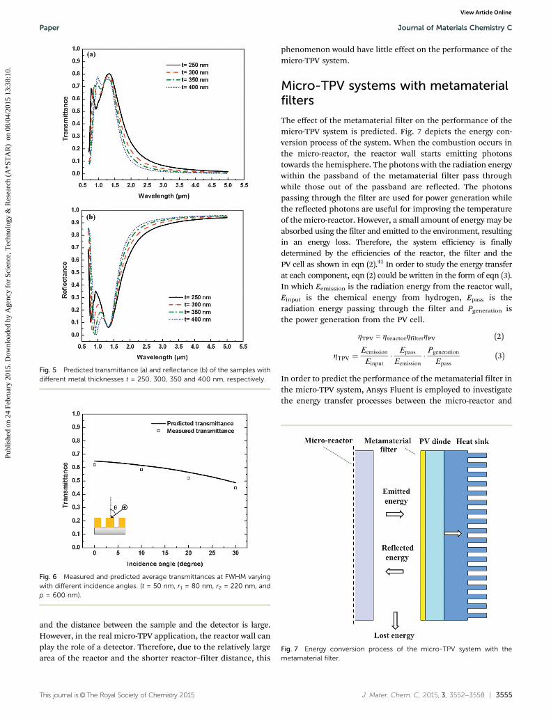
transmittance in a relatively long wavelength range. Thisproperty could be achieved by adjusting the thickness of thearray of coaxial rings. With reference to ref. 25 and 26, two CSPinduced transmittance peaks exist in the working wavelengthrange with the increase of metal thickness. The position of thered peak (at longer wavelength) is independent of the thicknessof the array of coaxial rings. However, with the increase ofthickness, the position of the blue peak (at lower wavelengths)moves towards the far-infrared direction. The movement ofthe blue peak causes the fluctuation at the wavelength between500–1000 nm. This is mainly because of the decrease of theresonant frequency of the cylindrical surface plasmon mode atthe increased metal thickness. When the two peaks merge,the wideband transmittance with high intensity would beachieved. This is favorable for the application in the micro-TPV system. Fig. 5(a) and (b) depict the transmittance andreflectance of the coaxial ring array with the metal thicknesst of 250, 300, 350 and 400 nm, respectively. It is obvious thatthe left transmittance peak red-shifts with the increase of themetal thickness. Besides, the value of the left peak increasessimultaneously. Expectedly, the red peaks show weak depen-dence on the metal thickness. However, their intensitiesdecrease slightly with the increase of t, which is mainly theresult of losses.26
As the reactor wall is a diffuse surface, it emits photonstowards the hemisphere. In this case, the incidence angle depen-dence becomes a key parameter to evaluate the performance ofthe metamaterial filter. Both numerical and experimental studieswere performed to identify the incidence angle dependence ofthe coaxial ring array. Fig. 6 shows the average transmittance atFWHM (full width at half maximum). It is found that thepredicted transmittance only decreases slightly with the increaseof incidence angles. Compared to experimental results, the mea-sured transmittance has a reasonable agreement with the predictedvalue. It is difficult to obtain the reflectance with different incidenceangles experimentally. This is due to the difficulty in collecting thereflected photons using the detector as the detector area is small
Fig. 3 Transmittance (a) and reflectance (b) of the coaxial ring array withthe period of 600 nm (t = 50 nm, r1 = 100 nm, r2 = 220 nm) and 900 nm(t = 50 nm, r1 = 140 nm, r2 = 360 nm). The inset of (a) shows the SEM imagesof the designs with 600 nm (top) and 900 nm (bottom) periods.
Fig. 4 Measured transmittance and reflectance of coaxial ring arrays withr1 of 140 nm (t = 50 nm, r2 = 360 nm, p = 900 nm) and 160 nm (t = 50 nm,r2 = 360 nm, p = 900 nm), respectively.
Journal of Materials Chemistry C Paper
Publ
ishe
d on
24
Febr
uary
201
5. D
ownl
oade
d by
Age
ncy
for
Scie
nce,
Tec
hnol
ogy
& R
esea
rch
(A*S
TA
R)
on
08/0
4/20
15 1
3:38
:10.
View Article Online
This journal is©The Royal Society of Chemistry 2015 J. Mater. Chem. C, 2015, 3, 3552--3558 | 3555
and the distance between the sample and the detector is large.However, in the real micro-TPV application, the reactor wall canplay the role of a detector. Therefore, due to the relatively largearea of the reactor and the shorter reactor–filter distance, this
phenomenon would have little effect on the performance of themicro-TPV system.
Micro-TPV systems with metamaterialfilters
The effect of the metamaterial filter on the performance of themicro-TPV system is predicted. Fig. 7 depicts the energy con-version process of the system. When the combustion occurs inthe micro-reactor, the reactor wall starts emitting photonstowards the hemisphere. The photons with the radiation energywithin the passband of the metamaterial filter pass throughwhile those out of the passband are reflected. The photonspassing through the filter are used for power generation whilethe reflected photons are useful for improving the temperatureof the micro-reactor. However, a small amount of energy may beabsorbed using the filter and emitted to the environment, resultingin an energy loss. Therefore, the system efficiency is finallydetermined by the efficiencies of the reactor, the filter and thePV cell as shown in eqn (2).41 In order to study the energy transferat each component, eqn (2) could be written in the form of eqn (3).In which Eemission is the radiation energy from the reactor wall,Einput is the chemical energy from hydrogen, Epass is theradiation energy passing through the filter and Pgeneration isthe power generation from the PV cell.
ZTPV = ZreactorZfilterZPV (2)
ZTPV ¼Eemission
Einput� Epass
Eemission� Pgeneration
Epass(3)
In order to predict the performance of the metamaterial filter inthe micro-TPV system, Ansys Fluent is employed to investigatethe energy transfer processes between the micro-reactor and
Fig. 5 Predicted transmittance (a) and reflectance (b) of the samples withdifferent metal thicknesses t = 250, 300, 350 and 400 nm, respectively.
Fig. 6 Measured and predicted average transmittances at FWHM varyingwith different incidence angles. (t = 50 nm, r1 = 80 nm, r2 = 220 nm, andp = 600 nm).
Fig. 7 Energy conversion process of the micro-TPV system with themetamaterial filter.
Paper Journal of Materials Chemistry C
Publ
ishe
d on
24
Febr
uary
201
5. D
ownl
oade
d by
Age
ncy
for
Scie
nce,
Tec
hnol
ogy
& R
esea
rch
(A*S
TA
R)
on
08/0
4/20
15 1
3:38
:10.
View Article Online

3556 | J. Mater. Chem. C, 2015, 3, 3552--3558 This journal is©The Royal Society of Chemistry 2015
the filter. A 3D model is established for the micro-reactor, the filterand the air between them. The dimensions of the reacting fluid are10 mm (length), 1 mm (width) and 18 mm (height), while thereactor wall has a thickness of 0.5 mm. The filter with thedimensions of 10 mm � 18 mm is parallel to the front surfaceof the reactor wall. The H2–air premixed flame is employed as thereacting fluid and modeled by a detailed chemical reactionmechanism with 9 species and 19 steps.42,43 The discrete ordinates(DO) model is utilized to study the radiative heat transfer betweenthe reactor wall and the filter. The air flow between the reactor walland the filter is set to be natural convection. The transmittanceand reflectance of the filter are obtained from the predicted resultsas shown in Fig. 3 ( p = 600 nm) by taking incidence angles (0–501)into account. The H2–air inlet flow velocity varies from 3–5 m s�1,while the distance between the front reactor wall and the filter isset to be 1, 2 and 3 mm, respectively.
Four cases are compared to evaluate the performance of themetamaterial filter. In case A, no metamaterial filter is installedon top of the PV cell, while the metamaterial filters are employedfor cases B, C, and D, where the distances between the filter andthe reactor wall for cases A, B, C, and D are 1, 1, 2 and 3 mm,respectively. In order to ensure the four cases to be comparable,the input energies of hydrogen are the same. Fig. 8 illustrates thereactor wall temperature distributions for the cases A, B, C and D,respectively. As shown in Fig. 8(a), the highest reactor walltemperature is obtained in case B, followed by case C, case Dand case A. Compared with that of case A, the higher reactor walltemperatures of case B, C and D can be attributed to the reflectedenergy from the metamaterial filters. Compared with case B, therelatively low reactor wall temperatures of case C and D are causedby the increased reactor–filter distance, which leads to a smallerview factor. With the increase of the flow velocity to 4 and 5 m s�1
(see Fig. 8(b) and (c)), the reactor wall temperature is found to beeven higher. This is because more hydrogen is brought in andmore chemical energy is released.
The predicted system efficiencies for the four cases areshown in Fig. 9 when the inlet flow velocity varies from3–7 m s�1. As shown in eqn (2), the micro-TPV system efficiencyis determined by the efficiencies of the reactor, the filter and PVcells. In this paper, the GaSb PV cell is employed for calculationand the efficiency is adopted from the study by Yang et al.44 Asobserved in Fig. 9, the system efficiency of case A increaseswhen the flow velocity increases from 3–5 m s�1 but decreaseswhen the flow velocity further increases from 5–7 m s�1. As thereis no filter applied in this case, the system efficiency would onlybe determined by the efficiencies of the reactor and PV cells. Theinitial increase could be attributed to the increased reactor walltemperature, which is caused by the more heat release. FromWien’s displacement law, the spectral irradiance would blue-shift when the source temperature increases. By this mecha-nism, more energy could be converted into electricity, and thesystem efficiency for case A increases. However, the efficiencydecrease when the inlet flow velocity increases from 5 m s�1
onwards could be due to the large amount of energy loss fromthe exhaust because of incomplete combustion. By employingfilters for cases B, C and D, the filter efficiencies decrease.However, the employment of the filter increases the efficienciesof the reactor and PV cells simultaneously. This is the reasonwhy the system efficiency of case B is higher than that of case A.With the increase of the reactor–filter distance, more energy lossis incurred by the reduced view factor. As a result, the reflectedphotons could not be collected using the reactor effectively. Thiswill lead to the decrease of reactor efficiency and wall tempera-ture. The decreased reactor wall temperature results in a reducedPV cell efficiency at the same time because of the red-shift of theradiation profile. As a result, the system efficiency for cases Cand D are lower than that of case B. These results imply that theperformance of a filter is not only judged by the transmittance,but also by the reflectance.
Fig. 8 Reactor wall temperature distributions at (a) 3 m s�1, (b) 4 m s�1
and (c) 5 m s�1. (Case A, without the filter; cases B–D with the filter andtheir reactor–filter distances are 1, 2 and 3 mm, respectively.)
Fig. 9 Predicted system efficiencies of the micro-TPV system with dif-ferent inlet flow velocities for the four cases. (Case A, without the filter;case B, with the filter and the reactor–filter distance of 1 mm; case C, withthe filter and the reactor–filter distance of 2 mm; case D, with the filter andthe reactor–filter distance of 3 mm) Lines connecting the symbols are onlyfor the sake of visualization.
Journal of Materials Chemistry C Paper
Publ
ishe
d on
24
Febr
uary
201
5. D
ownl
oade
d by
Age
ncy
for
Scie
nce,
Tec
hnol
ogy
& R
esea
rch
(A*S
TA
R)
on
08/0
4/20
15 1
3:38
:10.
View Article Online

This journal is©The Royal Society of Chemistry 2015 J. Mater. Chem. C, 2015, 3, 3552--3558 | 3557
Conclusions
The primary objective of this study was to develop a meta-material filter for micro-TPV application. The results showed thatthe normalized-to-area transmittance is more than unity, whichimplied that the extraordinary transmission could be achieved inthe near infrared wavelength range. To fulfill the demand for themicro-TPV system, the passband could be adjusted by changingthe period of the coaxial ring structure and a slight change couldalso be made by changing the inner radius of the ring. Thesefindings are of crucial importance for the micro-TPV system withdifferent bandgap PV cells. A wide band pass filter was createdwhen the metal thickness t is increased, which could be attrib-uted to the merging of the two CSP induced transmittance peaks.Besides, the metamaterial filter showed the angle-insensitivefeature in its working wavelength range. By increasing theincidence angle from 0 to 30 degrees, the decrease of transmit-tance is generally very slight. In order to analyze the whole energyconversion process from chemical energy into power generation,the micro-TPV system efficiency was predicted by incorporatingthe micro-reactor and the PV cell. Compared with the originalsystem, the system efficiency was found to be increased signifi-cantly after the metamaterial filter was employed, which shouldbe attributed to the improved performance of the reactor andthe PV cell. The developed wideband and angle-insensitivemetamaterial filter exhibits many outstanding features andprovides great potential to improve the performance of theexisting micro-TPV system.
Acknowledgements
This project is supported by the research grant R-265-000-460-112.
Notes and references
1 W. R. Chan, P. Bermel, R. C. Pilawa-Podgurski, C. H. Marton,K. F. Jensen, J. J. Senkevich, J. D. Joannopoulos, M. Soljacicand I. Celanovic, Proc. Natl. Acad. Sci. U. S. A., 2013, 110,5309–5314.
2 S. K. Chou, W. M. Yang, K. J. Chua, J. Li and K. L. Zhang,Appl. Energy, 2011, 88, 1–16.
3 Y. Ju and K. Maruta, Prog. Energy Combust. Sci., 2011, 37,669–715.
4 L. C. Chia and B. Feng, J. Power Sources, 2007, 165, 455–480.5 S. Basu, Y. B. Chen and Z. M. Zhang, Int. J. Energy Res., 2007,
31, 689–716.6 V. Rinnerbauer, A. Lenert, D. M. Bierman, Y. X. Yeng,
W. R. Chan, R. D. Geil, J. J. Senkevich, J. D. Joannopoulos,E. N. Wang, M. Soljacic and I. Celanovic, Adv. Energy Mater.,2014, 1400334.
7 H. Sai and Y. Kanamori, Microscale Thermophys. Eng., 2003,7, 101–115.
8 T. Bauer, I. Forbes, R. Penlington and N. Pearsall, Sol.Energy Mater. Sol. Cells, 2005, 88, 257–268.
9 I. Celanovic, F. O’Sullivan, M. Ilak, J. Kassakian andD. Perreault, Opt. Lett., 2004, 29, 863–865.
10 A. Licciulli, D. Diso, G. Torsello, S. Tundo, A. Maffezzoli,M. Lomascolo and M. Mazzer, Semicond. Sci. Technol., 2003,18, S174.
11 G. Torsello, M. Lomascolo, A. Licciulli, D. Diso, S. Tundoand M. Mazzer, Nat. Mater., 2004, 3, 632–637.
12 C. Argyropoulos, K. Q. Le, N. Mattiucci, G. D’Aguanno andA. Alu, Phys. Rev. B: Condens. Matter Mater. Phys., 2013,87, 205112.
13 J. Fleming, S. Lin, I. El-Kady, R. Biswas and K. Ho, Nature,2002, 417, 52–55.
14 V. Rinnerbauer, S. Ndao, Y. X. Yeng, W. R. Chan,J. J. Senkevich, J. D. Joannopoulos, M. Soljacic andI. Celanovic, Energy Environ. Sci., 2012, 5, 8815.
15 S. Molesky, C. J. Dewalt and Z. Jacob, Opt. Express, 2013, 21,96–110.
16 C. Simovski, S. Maslovski, I. Nefedov and S. Tretyakov,Opt. Express, 2013, 21, 14988–15013.
17 S. I. Mostafa, N. H. Rafat and S. A. El-Naggar, RenewableEnergy, 2012, 45, 245–250.
18 L. Fraas, J. Samaras, H. Huang, L. Minkin, J. Avery,W. Daniels and S. Hui, TPV generators using the radiant tubeburner configuration, 2001.
19 P. Bermel, M. Ghebrebrhan, W. Chan, Y. X. Yeng,M. Araghchini, R. Hamam, C. H. Marton, K. F. Jensen,M. Soljacic and J. D. Joannopoulos, Opt. Express, 2010, 18,A314–A334.
20 X. Liu, T. Tyler, T. Starr, A. F. Starr, N. M. Jokerst andW. J. Padilla, Phys. Rev. Lett., 2011, 107, 045901.
21 B. Zhao, L. Wang, Y. Shuai and Z. M. Zhang, Int. J. Heat MassTransfer, 2013, 67, 637–645.
22 R. T. Kristensen, J. Appl. Phys., 2004, 95, 4845.23 C. Wu, B. Neuner Iii, J. John, A. Milder, B. Zollars, S. Savoy
and G. Shvets, J. Opt., 2012, 14, 024005.24 T. W. Ebbesen, H. Lezec, H. Ghaemi, T. Thio and P. Wolff,
Nature, 1998, 391, 667–669.25 F. Baida and D. Van Labeke, Opt. Commun., 2002, 209,
17–22.26 M. Haftel, C. Schlockermann and G. Blumberg, Phys. Rev. B:
Condens. Matter Mater. Phys., 2006, 74, 235405.27 M. I. Haftel, C. Schlockermann and G. Blumberg, Appl. Phys.
Lett., 2006, 88, 193104.28 S. M. Orbons, A. Roberts, D. N. Jamieson, M. I. Haftel,
C. Schlockermann, D. Freeman and B. Luther-Davies,Appl. Phys. Lett., 2007, 90, 251107.
29 A. Belkhir and F. Baida, Phys. Rev. E: Stat., Nonlinear, SoftMatter Phys., 2008, 77, 056701.
30 G. Neuer and G. Jaroma-Weiland, Int. J. Thermophys., 1998,19, 917–929.
31 D. Jiang, W. Yang, K. J. Chua and J. Ouyang, Appl. Therm.Eng., 2013, 61, 670–677.
32 W. Yang, S. Chou, K. Chua, H. An, K. Karthikeyan andX. Zhao, Appl. Energy, 2012, 97, 749–753.
33 O. Sulima and A. Bett, Sol. Energy Mater. Sol. Cells, 2001, 66,533–540.
Paper Journal of Materials Chemistry C
Publ
ishe
d on
24
Febr
uary
201
5. D
ownl
oade
d by
Age
ncy
for
Scie
nce,
Tec
hnol
ogy
& R
esea
rch
(A*S
TA
R)
on
08/0
4/20
15 1
3:38
:10.
View Article Online

3558 | J. Mater. Chem. C, 2015, 3, 3552--3558 This journal is©The Royal Society of Chemistry 2015
34 O. Sulima, R. Beckert, A. Bett, J. Cox and M. Mauk, IEE Proc.:Optoelectron., 2000, 147, 199–204.
35 M. W. Dashiell, J. F. Beausang, H. Ehsani, G. Nichols,D. M. Depoy, L. R. Danielson, P. Talamo, K. D. Rahner,E. J. Brown and S. R. Burger, IEEE Trans. Electron Devices,2006, 53, 2879–2891.
36 L. Ferguson and L. Fraas, Sol. Energy Mater. Sol. Cells, 1995,39, 11–18.
37 G. Si, Y. Zhao, H. Liu, S. Teo, M. Zhang, T. Jun Huang,A. J. Danner and J. Teng, Appl. Phys. Lett., 2011, 99, 033105.
38 S. G. Rodrigo, Optical Properties of Nanostructured MetallicSystems, Springer, Berlin, Germany, 2012.
39 A. Popov, V. Sherstnev, Y. Yakovlev, R. Mucke and P. Werle,Appl. Phys. Lett., 1996, 68, 2790–2792.
40 F. I. Baida, D. Van Labeke and B. Guizal, Appl. Opt., 2003, 42,6811–6815.
41 M. Zenker, A. Heinzel, G. Stollwerck, J. Ferber and J. Luther,IEEE Trans. Electron Devices, 2001, 48, 367–376.
42 J. C. Andrae and P. H. Bjornbom, AIChE J., 2000, 46,1454–1460.
43 V. Giovangigli and M. Smooke, Combust. Sci. Technol., 1987,53, 23–49.
44 W. M. Yang, S. K. Chou, C. Shu, Z. W. Li and H. Xue, Sol.Energy Mater. Sol. Cells, 2003, 80, 95–104.
Journal of Materials Chemistry C Paper
Publ
ishe
d on
24
Febr
uary
201
5. D
ownl
oade
d by
Age
ncy
for
Scie
nce,
Tec
hnol
ogy
& R
esea
rch
(A*S
TA
R)
on
08/0
4/20
15 1
3:38
:10.
View Article Online