journal of engineering sciences and innovation
TRANSCRIPT
Journal of Engineering Sciences and Innovation Volume 6, Issue 2 / 2021, pp. 189-202
Technical Sciences
Academy of Romania F. Petroleum and Mining Engineering www.jesi.astr.ro
Received 29January 2021 Accepted 17 May 2021 Received in revised from 4 March 2021
Tackling wellbore difficulties for drilling deviated and
horizontal wells
AYHAM MHANNA, MOHAMED HALAFAWI, LAZĂR AVRAM
*
Drillling Engineering, Petroleum – Gas University of Ploiesti, Romania
Abstract. Future development plans are often being continued during production. These
plans includes wells repair, reservoir enhancements, or new development wells in order to
increase the field production. Therefore, the main objective of this paper is to tackle deviated
and horizontal wellbore difficulties in GOF field. Specific drilling hole problems are addressed and reviewed. Additionally, proposed solutions are suggested to improve wellbore
stability and select the appropriate hole cleaning drilling practices, based on offset data for
drilling the new development wells of Gulf Offshore Field (GOF) without instability
difficulties. Overview of this field is discussed including geological column, wells locations,
and contour maps. Offset wells data are completely analyzed. Drilling fluids are selected with
their properties that avoid wellbore obstructions. Moreover, deviated and horizontal
trajectories are optimized for the new development wells. Finally, the best drilling practices
are hence recommended.
Keywords: trajectory optimization, wellbore problems, drilling practices, horizontal wells.
Introduction
Oil fields are often required to be developed from time to time. One of the developments is drilling activity. Development wells are performed in order to
enhance the productivity of the oil field. Therefore, offset wells data surrounding the
drilling area should be collected in order to be checked and analyzed. After that, production plans and development strategy are obviously determined. The
importance of offset wells data appears during drilling new exploratory or
development wells. Adams [1] presented two different company strategies about
how the offset data of near wells influence drilling performance and operations. One of the two strategies was to maximize the benefit from the offset wells data by buying
these data with $800 and performing the drilling plan, while the other was to do
*Correspondence address: [email protected]
190 Ayham M. and al. / Tackling wellbore difficulties for drilling deviated…
nothing and to perform the drilling plan without obtaining the offset data. During drilling, the first helped to reach target safely while the other was exposed to
blowout, destroying rig and persons and the final settlement by the insurance
company was over $16 million instead of $800. Based on offset wells data; stratigraphy geological column, formation types, layers
depth, drilling problems, drilling operations, pressure profiles, formation troubles
and stability etc. may be determined and known for new wells. However, the
wellbores instability happen due to several causes which have previously been discussed by several textbooks and scientific articles [2-12]. Additionally, one of the
drilling problems, when encountered, can be very costly and influence the wells
stability if it is not treated well such as loss of circulation (LOC) and pipe sticking, hole enlargement etc. Most of wellbore stability models dealing with fracturing loss
were previously presented [7-12]. Additionally, Halafawi and Avram [10-11]
presented and identified the risk assessment for drilling problems and operations with field case studies.
In order to estimate the possible hazards and risks for controlling and reaching
the target safely with optimum profile, an understanding of wellbore problems, their
causes, their anticipation and planning for solutions is a key factor . Therefore, the stability and the trajectory optimization of new GOF development wells are also
required to be accurately determined in order to drill them safely.
In this article, complete drilling activities of GOF wells are addressed. The man issues of wells production, wellbore problems, their effects on well design, possible
solutions, and preventive measures are taken into account. Offset wells drilling data
are analyzed. Major problems of drilling wells are identified, detected, and treated.
Additionally, deviated and horizontal wellbores are optimized based on tackling trajectory obstructions.
Drilling well problems
During drilling operations, some types of the drilling problems will almost certainly
occur, even in very carefully planned wells. The reason is that geological conditions for two wells that are near each other may differ (nonhomogeneous
formation); therefore, different problems can be encountered. The key to success in
achieving well objectives is to design drilling programs based on anticipation of
potential hole problems, rather than on containment and caution. Drilling problems, when encountered, can be very costly and they are pipe sticking, lost circulation,
hole deviation, pipe failures, borehole instability, mud contamination, formation
damage, hole cleaning, H2S-bearing formations and shallow gas, and equipment & personnel-related problems (Fig.1). Details of the preceded problems are introduced
and discussed by several authors [1-12].

Journal of Engineering Sciences and Innovation, Vol. 6, Issue 2 / 2021 191
Well profiles for a wellbore trajectory optimization
The mathematical trajectory planning calculation and equations are the same as those
used in directional calculations, presented by many authors [1-7, 13-15]. However,
there is an exception that the primary unknown in the combination trajectory plan is the depth of kick off point (KOP). Additionally, the problems result in horizontal
turn trajectory, vertical turn computations, mud weight selection, building 3D profile
and survey methods selection.
Fig. 1. Drilling Problems (a, b, c) [7], (d, e, f) [2], and (g, h, I) [14]

192 Ayham M. and al. / Tackling wellbore difficulties for drilling deviated…
Fig. 2. Horizontal well Profile [15-16]
KOP, Horizontal Turn Trajectory, and Vertical Turn Determination. Authors [13-
16] discussed the mathematics for determining KOP in the combination trajectory of
horizontal well plan as follows:
𝑰𝒏𝒄𝒍𝒊𝒏𝒆𝒅 𝑻𝑽𝑫 = 𝑹𝟏𝒔𝒊𝒏𝟏 + 𝑻 𝐜𝐨𝐬𝟏 + 𝑹𝟐(𝒔𝒊𝒏𝟑 − 𝒔𝒊𝒏𝟏) (1)
𝑰𝒏𝒄𝒍𝒊𝒏𝒆𝒅 𝑫𝑬𝑷 = 𝑹𝟏(𝟏 − 𝒄𝒐𝒔𝟏) + 𝑻 𝐬𝐢𝐧𝟏 + 𝑹𝟐(𝒄𝒐𝒔𝟏 − 𝒄𝒐𝒔𝟑) (2)
𝑰𝒏𝒄𝒍𝒊𝒏𝒆𝒅 𝑴𝑫 = 𝑹𝟏 𝟏 + 𝑻 + 𝑹𝟐𝟐 (3)
𝑫𝒆𝒑𝒂𝒓𝒕𝒖𝒓𝒆 𝒐𝒇 𝒕𝒉𝒆 𝑹𝑬𝑨𝑪𝑯 = 𝑹𝑬𝑨𝑪𝑯 𝒙 𝒔𝒊𝒏𝟑 (4)
𝑪𝒉𝒂𝒏𝒈𝒆 𝒊𝒏 𝑻𝑽𝑫 𝒐𝒇 𝒕𝒉𝒆 𝑹𝑬𝑨𝑪𝑯 = 𝑹𝑬𝑨𝑪𝑯 𝒙 𝒄𝒐𝒔𝟑 (5)
where REACH = The along the hole distance (MD) of portion of the hole which is
normally thought to be horizontal
MD = Measured depth, ft Dep = Departure length, ft
T= Tangent length, ft
R1= Radius of curvature for upper build, ft
R2= Radius of curvature for lower build, ft
= Inclination angle for position 1, 2, and 3 (3=90o), degrees The sets of the above equations are solved simultaneously to determine KOP (Fig.
2). The appeared problems during planning a horizontal turn and a vertical turn in
the horizontal section of the planned wellbore are determined and solved [13-16]
Mud Weights Selection for Horizontal Wellbore. Methods of mud weight choice in
vertical well are not the same as in directional or horizontal holes. Consequently,
Mitchell [2] presented a method for determining mud densities (ppg) in order to stabilize deviated and horizontal wells:
𝑴𝑾𝒉𝒐𝒓𝒊𝒛𝒐𝒏𝒕𝒂𝒍 = 𝑴𝑾𝒗𝒆𝒓𝒕𝒊𝒄𝒂𝒍 + (𝑶𝑩𝑾 − 𝑳𝑶𝑻)𝟏−𝒄𝒐𝒔𝟐𝝋
𝟏.𝟔 (6)

Journal of Engineering Sciences and Innovation, Vol. 6, Issue 2 / 2021 193
where
WM= Mud weight, ppg, OBW = Overburden weight (Overburden stress), ppg,
LOT= Leak off test value, ppg,
= Inclination, degrees.
In order to perform wellbore trajectory optimization, it is required to determine the
best well profile survey parameters. The five methods [7], which are used to implement survey calculations, are average angle method (AAM), radius of
curvature (RCM), constant build and turn rate (CBTM), constant curvature and build
rate (CCBM) (constant tool face), and minimum curvature method (MCM).. However, MCM is the most used by the petroleum industry for both well-trajectory
planning and directional-survey evaluation [7]. Recently, Sawaryn and Thorogood
[17] presented algorithms for directional-well planning and deflection-tool
orientation. MCM equations are simply deduced from these algorithms:
𝑅𝐹 =∆𝑀𝐷
𝛽tan
𝛽
2 (7)
∆𝑋 = (𝑠𝑖𝑛𝜑1𝑐𝑜𝑠𝜗1 + 𝑠𝑖𝑛𝜑2𝑐𝑜𝑠𝜗2)𝑅𝐹 (8)
∆𝑌 = (𝑠𝑖𝑛𝜑1𝑠𝑖𝑛𝜗1 + 𝑠𝑖𝑛𝜑2𝑠𝑖𝑛𝜗2)𝑅𝐹 (9)
∆𝑍 = (𝑐𝑜𝑠𝜑1 + 𝑐𝑜𝑠𝜑2)𝑅𝐹 (10)
where RF= Ratio Factor, = Dog-leg angle, deg, =inclination angle, deg.
ϑ=Azimuth angle, deg.
Offshore gof field description
GOF field is an offshore oil reservoir field with various faults. Geological column
for the GOF field is shown in Fig.3.Structural map for reservoir pay zones and reference wells location is shown in Fig.4. Due to geological obstructions, all drilled
wells in this field are deviated and horizontal wells. Based on the result of the update
simulation study and the new geological model, it is recommended to side track the
well due South East from the original hole to hit sandstone in higher position. The first objective of the well is to drain the oil accumulated within the sandstone
reservoir. It is expected to be penetrated at depths 4000 and 6020 ft TVDSS with
vertical thickness 30 ft. Entering sand layers and basement are considered as the second objective and expected to have more than 40 ft cumulative vertical thickness
of sandstone.

194 Ayham M. and al. / Tackling wellbore difficulties for drilling deviated…
Fig.3. Geological column for GOF field.

Journal of Engineering Sciences and Innovation, Vol. 6, Issue 2 / 2021 195
Fig.4. Structural map for reservoir pay zones and reference wells location.
Future development plans
Each company has its own plans for future performance in order to keep its position in the competitive market of the petroleum industry. These future plans are divided
into plans of increasing the production and plans of exploring new fields. The present
plans for our company is a development strategy. In order to maximize the oil
production GOF field reservoir, development wells are, therefore, required to be drilled. There are several wells producing from this field. Two wells, which will be
drilled to develop new zones, are called GA-1A and GA-9A. Well objectives include
the followings. ➢ The strategic objectives are:
▪ to withdrawal & produce the attic oil existed as up dip of reservoir
▪ to prove the oil potential indicated by the dynamic data
▪ to locate the undeveloped locations of the incremental potential ▪ to drain the undeveloped reserves in the most up dip part towered east direction
of the field
➢ The technical objectives are: ▪ no harm to people, environment or property
▪ well delivery within planned time
▪ evaluating the fluid content and stratigraphy of Upper Cretaceous sands and basement
196 Ayham M. and al. / Tackling wellbore difficulties for drilling deviated…
▪ providing reservoir data from LWD GR/RES/Neutron / Density logging equipment while drilling and from W/L logging tool including Gamma Ray
/Resistivity/DIP METER /MDT/USITCBL/FMI in case Upper cretaceous sand
is an oil pay.
Tackling potential drilling hazards
Tackling obstructions of GOF field is a vital way to optimize wellbore trajectory. These obstructions include the followings:
Abnormal Pressure/Saltwater Flow. All pore pressure indicators must be closely
monitored and mud weight increased accordingly to maintain sufficient overbalance for safe drilling practices. Rams should be tested to 300 till 3000 psi and annular ram
to 1500 psi. All tests should be 10 min/10 min test (which means every test should
be 10 min followed by the second one which will last also 10 min. i.e testing the ram with 300 psi lasts 10 min and testing for higher pressure ( i.e 600 psi) lasts also 10
min.) using cementing unit and recorded on charts. The IBOP, drilling hose, mud
stand pipe should be tested to 5000 psi. All subsequent BOP tests should be carried
out on a 3-week basis. The volume of the test fluid pumped shall be monitored and recorded. Depending on the exact FIT at the 9-5/5-in casing window (FIT to 15 ppg)
and the mud weight is in use while drilling, the kick tolerance within the 8.5-in
interval could be ± 2.0-ppg. With this in mind, it is imperative that the entire rig crew constantly monitor the well for any abnormal conditions and pit drills should be held
on a frequent basis. In addition, no transfer of fluid shall take place over long periods
of time. If any fluid is added to the active system, it will be done by incorporating
the new pit as part of the active system on all monitoring systems. Subnormal Pressure/Lost Circulation. The rig site team should be very observant
of losses and should monitor drilling practices such as trip speeds, pump rates, etc.
in order to minimize the potential for losses. If losses occur, every attempt should be made to heal the loss zone prior to drill ahead (drilling policy states to keep the
annulus full with mud, but if there is no more mud, it is advisable to use sea water
or diesel according to mud type to keep annulus full). If losses are observed while drilling, losses should be reduced by controlling the drilling conditions and not just
decreasing mud flow rate in order to continue drilling ahead.
Mobile Formation - Salt Creep – Reactive Shale. Low salinity water pills should be
ready to be pumped around the BHA if salt creep happens. Also drilling these formations with salt saturated mud reduces the sticking tendency (MWT with12 ppg
and CL with 185 Kmg/l). Inhibited water base mud with KCL (7%) will be used to
stabilize shale problems during drilling 8.5" hole. Differential Sticking. Every attempt should be made to minimize the potential for
differential sticking. This includes the utilization of spiral drill collars, minimizing
the length of the BHA, maintaining a thin, hard filter cake, and keeping the pipe moving at all times possible. If the pipe does become differentially stuck, if possible,
immediately the pipe should be landed down with right hand torque in order to free
the pipe.

Journal of Engineering Sciences and Innovation, Vol. 6, Issue 2 / 2021 197
Drill String Washout/Twist off. There are many drill string washout cases in the
offset wells, so, the drill pipes and all BHA should be inspected very well before running into the hole. Also, the sand content should be minimized as low as possible,
especially during surface hole which drilled into massive loose sand. In order to
reduce the sand content, drilling crew and mud engineer need to pay attention to the efficiency of solids control equipment, specially the shakers and de-sanders.
Hydrogen Sulfide. No H2S recorded in the offset wells, so it is very low probability
to have H2S in this well, reservoir.
Down Hole Tools Reliability. One of the drilling risks expected is the down hole tools reliability particularly Jars, MWD and Motors in the 8.5" and 6" hole section.
All precautions should be taken to ensure the tools have passed the QA/QC
standards. Quality check will be reviewed by drilling supervisor for quality assurance.
▪ Drilling equipment, DP, DC, and BHA need to be inspected to DS-1 category -
4. ▪ All equipment should have inspection certificate on connection and body.
▪ Company man should check the certificate validity for any equipment.
Incompetent personnel. One of the drilling risks should have good experience hands
on the rig and pre-agreed before job.
Fig.5. Selected mud weight for well GA-9A.
Fig.6. Mud Properties for well GA-9A.
8
9
10
11
0 1000 2000 3000 4000 5000 6000 7000
Mu
d W
eigh
t (P
PG
)
Depth (FT)
0
10
20
30
40
50
60
70
0 2000 4000 6000 8000
Mu
d R
heo
logy
Depth (FT)
yp
pv
198 Ayham M. and al. / Tackling wellbore difficulties for drilling deviated…
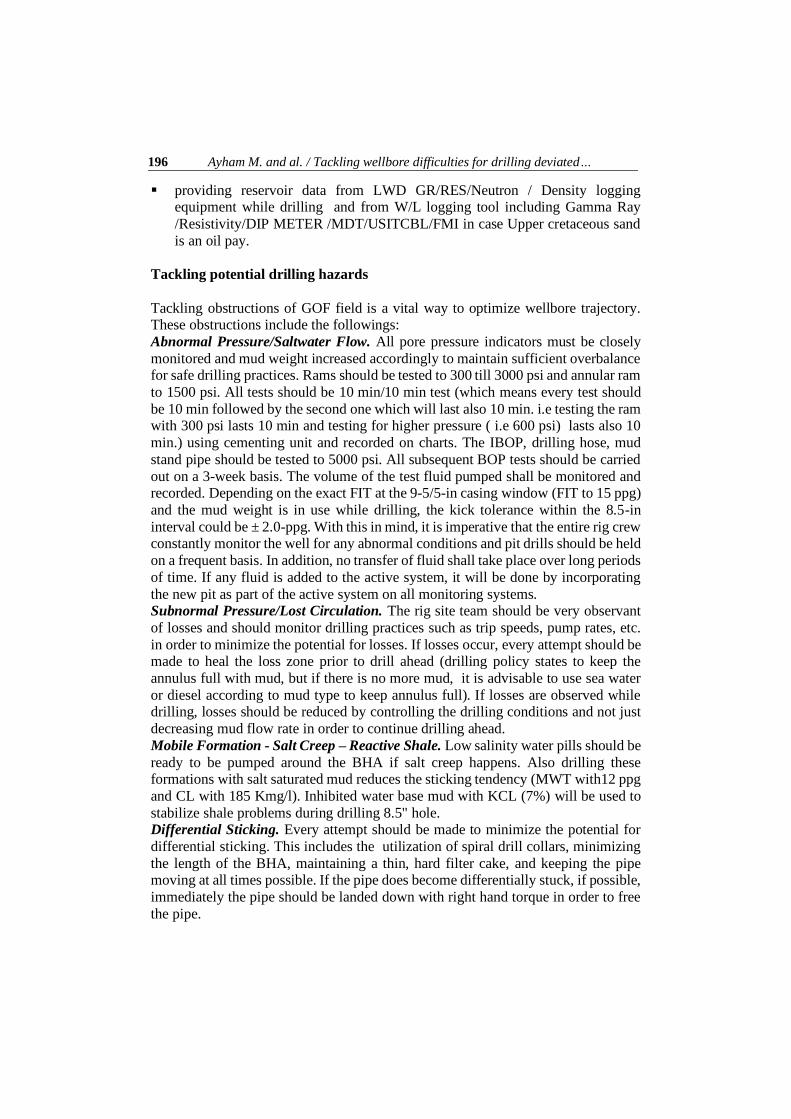
Table 1. Mud Properties for well GA-1A.
Interval 1450-5286 ft MD 6" Hole Interval 5286-5570 ft MDRT
Fluid properties Min. Max
.
Fluid properties Min. Max.
Mud type WBM WBM
Mud type LSND Polymer Mud
Mud weight (ppg) 11.5 12 Mud weight (ppg) 9.2 9.4
Viscosity (sec/Q) 50 60 Viscosity (cp) 45 50
Plastic Viscosity (cp) ALAP AL
AP
Plastic Viscosity
(cp)
ALAP ALAP
Yield Point (lb/100ft2) 20 27 Yield Point (lb/100ft2)
20 25
6 RPM (Low Shear YP) 8 12 6 RPM (Low Shear YP)
8 10
Zero second Gel 10 15 Zero second Gel 5 10
Ph 9.5 10 Ph 9.5 10
HPHT fluid loss (cc/30min)
8 12 HPHT - -
API fluid loss (cc/30min) 4 6 API fluid loss (cc/30min)
5 8
Chloride/CaCl2 (k mg/l) 180 190 Chloride/CaCl2 (k
mg/l)
130 156
Drilling fluids selection
In order to overcome wells GA-1A and GA-9A problems during drilling, the mud density and its properties are determined and plotted in Figs. 5 and 6, and Table 1.
The dynamic pressure profile for are estimated from reservoir pressure for well GA-
1A as follows: ➢ basement estimated reservoir pressure and EMW are:
▪ initial reservoir pressure = 2240 psi @ 4450 TVDss ( EMW=9.5 ppg),
▪ estimated current reservoir pressure =1900 psi @ 4450 TVDss ( EMW=8.1 ppg),
➢ sand zone estimated reservoir pressure and EMW :
▪ initial reservoir pressure = 2240 psi @ 4450 TVDss (EMW=9.5 ppg),
▪ estimated current reservoir pressure=1800 psi @ 4450 TVDss (EMW=7.6 ppg).
For 8 1/2" hole section, The SSM/Polymer WBM will be used to drill this section
with the following specifications in order to ▪ prevent stuck pipe in Evaporite salt,
▪ inhibit shale reactivity
▪ minimize/mitigate losses or differential sticking possibilities in sand zones.
Salt saturated water base mud system with weight of 12 ppg will be used in an attempt to obtain sufficient borehole stability to drill, evaluate and quickly case-off
these formations. Prior entering shale zone with +/-300', the system will be loaded
with 7% KCL. The primary reason for this selection is to ensure approaching maximum well-bore stability while drilling into the most problematic reactive shale
of that section. The 6'' hole section is composed mainly of granite. API filtrate should

Journal of Engineering Sciences and Innovation, Vol. 6, Issue 2 / 2021 199
be controlled within a tight value. Hole deviation should not represent any
difficulties within 62o inclination. Still, tripping practices must be considered all the time especially within the reservoir intervals. Salt will be the weighting material for
this interval to minimize the formation damage.The following mud properties should
be used as a guideline for optimizing the mud system while drilling this section.
Selection of the optimum wellbore trajectory
Based on offset wells' analysis, tackling hole problems, wellbore stability and stratigraphic column; the optimum borehole trajectory is selected for two
development wells. Well GA-1A will be deviated well while well GA-9A will be
horizontal well (Fig.7). For well GA-1A, the 8 -1/2” hole has been drilled directionally with rotary steerable
assembly. The direction work will be achieved while drilling 8-1/2" hole through
evaporite formation building angle from 1.72 degrees to 62 degrees and turning to
right from 310 to 347 degree azimuth with 3 degree dog leg severity. EOB will be at +/- 3,535 ft MDRT, then A tangent section till the rest of 8-1/2" section. 6" hole
section will be drilled maintaining angle and direction to well final total depth. 60'
will be drilled into Basement till getting log density neutron recorded 1st foot of basement set 7" liner at ± 5,240 ft MDRT. The Geological target shape is circle with
200' radius. Use Drilling target with 95% confidence. The hole is planned to hold
angle at 62° and azimuth at 347° to the section TD of 5,570 ft MDRT. Rotary
assembly will be used to clean out 7" liner and drilling Basement formation. A rotary assembly will be used to drill through rest of Basement to TD at 5,570' MDRT (4,000
TVDSS). This section helps to eliminate pipe stationary and to improve the wellbore
conditions. On the second well profile (Well GA-9A), the well is sidetracked due to formation
problems and thickness. The horizontal well profile is found be the optimum one to
hit target around 90 degrees with 9o /100 ft maximum dogleg severity and 1.03
o/100ft at the total depth (4449 ft TVD, 5975 ft MD).
Recommendations and best drilling practices
In these wells, drilling practices have a lot of impact on the success of the well. The
risk of differential sticking, mechanical sticking (Salt creep) is considered high, and
all effort must be made to avoid these major NPT events. The following are best practices and guidelines gathered based on offset data analysis to mitigate these risks.
1. Best practices to avoid differential sticking. These guidelines were copied from
the hole problem data package manual and textbooks, summarizing best practices to
avoid differential sticking. 2. Best practices during drilling include the following.
▪ Failure to clean the hole as fast as it is being drilled can cause serious hole
problems. Select the hole cleaning to match the maximum instantaneous penetration rate.

200 Ayham M. and al. / Tackling wellbore difficulties for drilling deviated…
(a)
(b)
Fig.7. The optimum trajectory (a). Well GA-9A, (b).Well GA-1A

Journal of Engineering Sciences and Innovation, Vol. 6, Issue 2 / 2021 201
▪ Monitor the hole constantly for changes in drilling trends. Record the magnitudes
and depths of high torques and drags. Always know the bit and stabilizer depths relative to trouble spots. Check the shakers regularly for changes in shape and
volume of cuttings.
▪ Perform wiper trips as hole conditions dictate. A wiper trip interval can be based on either time or footage (e.g. every 1000 ft drilled, or every 12 hours in mobile
formations). Specify a wiper trip interval in any instructions but be prepared to alter
this if hole conditions change.
▪ Wipe/ream the last single before making a connection in difficult hole conditions (last stand with a top drive). Circulate for as long as possible before a connection.
Avoid turning pumps off before picking up. NOTE: The hole may need wiping more
often than once per stand with the top drive as fewer connections are made. ▪ Wipe the last single or stand before taking a survey. Keep the pipe moving while
the survey can wait.
▪ When drilling to casing point, a target depth should be calculated based on the casing tally. The rathole below the casing shoe should also be minimized (generally
3-5 ft unless local conditions say otherwise) because the excessive rathole can cause
hole cleaning problems, keyseating, and backing off the casing shoe joint.
3. Best practices during hole cleaning are given below: ▪ Circulate at maximum recommended GPM for hole size.
▪ Do not allow the penetration rate to exceed the ability to clean the hole
▪ Record torque and drag trends for symptoms of inadequate hole cleaning. ▪ Conceder wiper trip after drilling long section.
▪ Wipe the hole at full circulation rate as long as possible (5-10min) before
connection.
▪ Maximize string motion when circulating the hole clean. Use maximum practical RPM (revolutions per minute), raise the drill string slowly (5min/st) and slack-off at
a safe but fast rate (1min/st)
▪ Consider low vis/high vis sweeps 4. Best practices during tripping are:
▪ Plan the trip: know where all the potential trouble spots are from drilling and from
previous trips. ▪ Compare drags/fill volumes with previous trips to monitor hole
improvement/deterioration.
▪ Ensure trip notes are recorded and handed over at shift change.
▪ Know the swab and surge pressures (get these from the mud loggers). Do not exceed the maximum allowable pipe speed when tripping, otherwise well control or
formation instability problems may result.
Conclusions
Based on the results and analysis, the following conclusions are extracted:
▪ GOF offset wells' analysis enhances the performance of new development wells. ▪ Offset well analysis can identify major problems of GOF stratigraphic column
and reduces the non-productive time for future operations.

202 Ayham M. and al. / Tackling wellbore difficulties for drilling deviated…
▪ Future development plans of GOF field are improved by enhancing drilling well stability and identifying the best hole cleaning practices.
▪ Drilling fluid selections and their properties help to solve well problems.
▪ Planned pressure profiles for new wells are exactly determined with the expected zone in which problems appear.
▪ Borehole trajectory optimization for deviated and horizontal wells are designed
based on tackling hole difficulties.
References
[1] Adams N.J., Drilling engineering: a complete well planning approach, PennWell Publishing Company, 1985. [2] Azar J.J., G. Samuel G.R., Drilling engineering, PennWell Corporation, USA, 2007. [3] Bourgoyn A.T., Millheium K.K., Chenevert M.E., Young F.S., Applied drilling engineering, SPE
text series, Volume II, 1991. [4] Darley H.C., Gray G.R., Composition and properties of drilling and completion fluids, Houston, Gulf Publishing, 1988. [5] Hossain M. E., Al-Majed A.A., Fundamentals of sustainable drilling engineering, Scrivener Publishing LLC., Wiley, Canada, 2015. [6] Rabia H., Well engineering and constructions, Entrac Consulting, ISBN: 0954108701, 2002. [7] Robert F.M., Stefan Z.M., Fundamentals of drilling engineering, SPE, 2011. [8] Halafawi DIM, Avram DIL, Wellbore instability prediction and performance analysis using
Poroelastic modeling, J Oil Gas Petrochem Sci., 2, 2, 2019, p. 93-106. [9] Halafawi M., Avram L., Borehole insitu stress stability analysis of RBS-9 field utilizing the inversion technique, Journal of Engineering Sciences and Innovation, Petroleum and Mining Engineering, 4, 1, 2019. [10] Halafawi M., Avram L., Application of risk analysis in drilling well problems and operations - field case study, Journal of Engineering Sciences and Innovation, Petroleum and Mining Engineering, 3, 4, 2018. [11] Halafawi M., Avram L., Well integrity, risk assessment and cost analysis for petroleum fields and
production wells with CO2, International Journal of Innovations in Engineering and Technology (IJIET), Petroleum Engineering Section, 10, 4, 2018. [12] Hareland G., Salehi S., Wellbore stability analysis in UBD wells of Iranian fields, 15th SPE Middle East Oil and Gas Show and Conference held in Bahrain International Centre, Kingdom of Bahrain, 11-14 March 2007. [13] Tahir M., Halafawi M., Wiercigroch M., Avram L., Optimum well trajectory design and optimization based on numerical optimization method PSO algorithm and wellbore stability, Petroleum and Coal Journal, 62, 1, 2020, p. 114-128. [14] Robert F.M., Lake L.W., Petroleum engineering handbook, 2nd edition, Drilling Engineering’’,
SPE, 2006 [15] Mitchell B.J., Advanced oil well drilling engineering handbook and computer programs, USA Library of Congress, 1974 to Mitchell Engineering, 10th edition, 1st revision, July 1995 [16] Halafawi M., Avram L., Wellbore trajectory optimization for horizontal wells: the plan versus the reality, J Oil Gas Petrochem Sci., 2, 1, 2019, p. 49-54. [17] Sawaryn S.J., Thorogood JL., A compendium of directional calculations based on the minimum curvature method, SPE Annual Technical Conference and Exhibition. Society of Petroleum Engineers; 2003.
[18] Tudorache V.P., Avram L., Antonescu N.N., Aspects on offshore drilling process in deep and very deep waters, Journal of Engineering Sciences and Innovation, Petroleum and Mining Engineering, 5, 2, 2020, p. 157-172. [19] Halafawi M., Avram L., Mhanna A., El Dilbani A., Integrated risk assessment improves Colibasi field drilling performance, Oil and Gas Journal, USA, 118, 9, 2020, p. 50-55. [20] El Gabouri H., Halafawi M., Avram L., Offset-well data improve Zubair wellbore stability, Oil and Gas Journal, USA, 118, 1, 2020, p. 38-43.