journal of advanced mechanical design, systems, and manufacturing
TRANSCRIPT

Journal of Advanced Mechanical Design, Systems, and
Manufacturing
146
Vol. 2, No. 1, 2008
Circular Vibration Planing of Inconel 718 -An Analysis of Surface Finish and Tool Wear-*
Nandita Kalyanakumara HETTIARACHCHI**, Toshimichi MORIWAKI***, Toshiro SHIBASAKA**** and Keiichi NAKAMOTO*****
** Department of Mechanical and Systems Engineering, Graduate school of science and technology, Kobe University, 1-1 Rokko-dai, Nada, Kobe 657-8501, Japan
***Department of Industrial and Systems Engineering, Setsunan University, 17-8 Ikedanaka-machi, Neyagawa, Osaka 572-8508, Japan
**** Department of Mechanical Engineering, Graduate school of Engineering, Kobe University, 1-1 Rokko-dai, Nada, Kobe 657-8501, Japan
***** Department of Mechanical Engineering, Graduate school of Engineering, Osaka University, 2-1 Yamada-oka, Suita, Osaka 565-0871, Japan, E-mail: [email protected]
Abstract Circular vibration milling (CVM) is achieved by vibrating a milling cutter about the machine tool spindle axis in a circular path, in addition to its rotary motion. CVM has been proven capable of producing better surface finishes on difficult to cut materials. However, the CVM process is far slower than conventional milling process. In circular vibration planing (CVP) process, the cutting tool is clamped without rotation and fed at a speed comparable to the feed speed of conventional milling. By superimposing circular vibration motion, necessary cutting speed could be achieved keeping the feed speed at realistic values. Inconel 718 was machined by CVP and conventional milling at a similar feed rate. It was observed that CVP could reduce tool wear and hence produce better surface finishes than conventional milling. A geometric simulation showed a major difference between uncut chip shapes of the two processes. The difference of uncut chip shapes suggests that in CVP process, less rubbing occurs between tool flank face and work before the tool penetrates in to the work to form a chip. The reduced rubbing of the flank face is proposed as the reson for reduced tool wear in CVP when compared with conventional milling.
Key words: Circular Vibration Planing, Inconel 718, Ball End Milling, Surface Finish, Tool Wear
1. Introduction
Vibration assisted cutting is proposed to overcome the machining difficulty of hard to machine materials. In the vibration assisted cutting, the cutting tool is fed at a nominal cutting speed and at the same time vibrated in an elliptical locus. As the maximum vibrating speed is set to be several times higher than the cutting speed, the cutting is taken place intermittently in each cycle of vibration. Chip thickness, cutting force and tool wear are reduced remarkably and surface roughness is much improved as compared with ordinary cutting (1). In order to apply the technology in practice, an ultrasonic elliptical vibration tool was developed (2), and ultra precision diamond turning of hardened steel was realized. This was impossible by ordinary cutting because of extremely rapid wear of diamond tool tip(3, 4).
Inconel 718 is a super alloy containing 53% Ni, 19% Fe, 17% Nb, 5% Mo, 3% Co and traces of Al, Ti, Al, Si, Mn, and carbon. It is one of the most sought after alloys in high
*Received 19 Nov., 2007 (No. 07-0749) [DOI: 10.1299/jamdsm.2.146]

Journal of Advanced Mechanical Design,Systems, and Manufacturing
Vol. 2, No. 1, 2008
147
temperature and corrosion resistant applications. Due to its good tensile, fatigue, creep and rupture strength, this advanced material is
used in the manufacture of components for liquid rockets, parts for aircraft turbine engines, cryogenic tanks, etc. Hence, nowadays the ability to machine Inconel 718 is increasingly demanded (5).
Tool life obtained when machining nickel-based alloys is severely inadequate. Most of the major parameters including the choice of tool materials, tool geometry, machining method, cutting speed, feed, depth of cut, etc. must be controlled in order to achieve adequate tool life during machining (6).
The outstanding feature in the machining of nickel-based alloys is that tool temperatures are far higher than in machining of conventional steels due to their high strength, low thermal conductivity, etc. (6).
Conventional ball end milling faces the difficulty of reduced cutting speed towards the tool center. It is the cutting action near the center of the ball end mill that gives the final finish of the cut surface. It is also to be noted that, the cutting action near the tool axis is close to orthogonal cutting in conventional ball end milling. In contrast, the cutting speed near the tool axis does not reach to zero in the case of circular vibration ball end milling. Further, the oblique cutting action of circular vibration milling is believed to reduce the effective shear angle. This phenomenon is advantageous to improve the finished surface quality. A series of cutting tests were carried out in the present research to investigate the surface roughness as well as the tool wear in circular vibration ball end milling of Inconel 718, which is a typical difficult-to-cut material (7).
With the success of the ultra precision vibration turning, the vibration assisted machining technology was extended to high precision milling. A prototype vibration milling machine as shown in Fig. 1 was developed (8) to investigate the feasibility of the vibration milling process. Feasibility of vibration assisted milling process has been experimentally proven by using the double spindle prototype vibration milling machine mentioned above. But the double spindle structure makes it a specific machine tool, which costs higher than normal machining centers with similar performance. To overcome these limitations, a circular vibration milling attachment was designed and developed. The attachment can be used with commercially available milling machines in a similar way as an interchangeable milling cutter (9). The developed attachment was fitted on to Mori Seiki’s GV4000/5AX five axis machine tool and a series of ball end milling experiments was performed.
Preliminary experiments of circular vibration milling showed that the finished surface roughness obtained by using the commercially available four flute tool was inferior to that obtained by using a custom made tool having two flutes with zero helix angle and large relief angle. Further, commercially available ball end mills with small relief angle are not suitable for circular vibration milling because of possible collision of relief face with the workpiece. Therefore the rest of the circular vibration milling experiments was performed by using custom made ball end mills having a large relief angle and zero rake angle cutting edges (7).
Although the tool wear could be reduced and the surface finish could be improved by the circular vibration milling process, its productivity was far lower than conventional milling. Simulation of the circular vibration milling shows that the idling time of the cutting edge without engaging with the workpiece was too long compared with that of the conventional milling process. It was the reason for the circular vibration milling had to be restricted to low feed rates.
2. Circular Vibration Planing
Conventional planing can be considered as having better tool-work engagement compared to milling, during a cutting stroke. However, cutting speed of the planing process

Journal of Advanced Mechanical Design,Systems, and Manufacturing
Vol. 2, No. 1, 2008
148
Fig. 1 Prototype double spindle machine
Fig. 2 Plot of successive cutting edge positions of circular vibration planing
is restricted to the feed speed itself. Our attempt to cut Inconel 718 by conventional planing led to premature chipping and breakage of cutting edge. Severe tool chatter occurred when conventional planing was tried on the double spindle machine which is schematically shown in Fig. 1. Therefore it is assumed that the cutting speed which is equal to feed rate of the machine was not sufficient to generate a stable chip of Inconel 718 in the conventional planing mode.
To overcome the low cutting speed in conventional planing, it is proposed in this research to superimpose the linear feed motion of the conventional planing process with a circular vibration motion. The circular vibration motion of the cutting edge provides the necessary cutting speed.
Figure 2 shows a plot of successive positions of the cutting edge of a ball end mill used for circular vibration planing. The cutting edge can be considered as a straight line because the effect of helix angle is negligible near the tool center. The inclination angle of the cutting edge with respect to the feed direction and pick feed direction is shown as α. It can also be seen from the Fig. 2 that the cutting edge moves forward in the feed direction and then to the left (opposite of the pick feed direction) before reversing its direction of motion. This action leads to intermittent cutting, in contrast to conventional planing, where the tool is continuously engaged during a cutting stroke. The intermittent cutting action helps avoiding the formation of continuous chips also, which may be a major concern in conventional planing.
α
Feed
Pick feed
Path of the tool center
Flexible link
Eccentric sleeve
Cutting tool
Eccentricity 0 5
Machine tool axis Cutting tool axis
Built-in motor for tool vibration
AC servo motor for tool rotation

Journal of Advanced Mechanical Design,Systems, and Manufacturing
Vol. 2, No. 1, 2008
149
Fig. 3 Tool – work geometrical relationship
0
20
40
60
80
100
120
0 2000 4000 6000 8000 10000Spindle speed min-1
Cut
ting
spee
d m
/min
Vmin - MillingVmax - MillingVcvp
Fig. 4 Cutting speeds of conventional milling and circular vibration planing
for tool inclination angle θ = 8o
Figure 3 shows the tool – work relationship of ball end milling or circular vibration planing. At a tool rotation speed of 5000 min-1, depth of cut of 100 µm and tool inclination angle of 8o, the cutting speeds at minimum contact radius and maximum contact radius become 22 m/min and 52 m/min respectively. The magnitude of cutting speed of the circular vibration planing process is equal to the product between the tool vibration radius (tool axis eccentricity) and the vibration rate. The vibration radius is a fixed value 0.5mm, which is the off-set distance of machine spindle axis and cutting tool axis (see Fig. 1). At a tool vibration rate of 5000 min-1, the resulting cutting speed is 15.7 m/min.
Figure 4 shows variation of cutting speeds of the two processes, when the tool inclination is 8o. Vmin-Milling and Vmax- Milling are cutting speeds at the minimum contact radius RMinContact and Maximum contact radius RMaxContact respectively. It is clear that for a given spindle speed and tool inclination angle θ, the cutting speed of circular vibration milling is lower than that of the conventional milling. Generally, higher the cutting speed, the higher the cutting edge temperature becomes. Therefore, it can be assumed that the cutting edge temperature is also low in case of circular vibration planing process, resulting in reduced tool wear.
3. Experimental Conditions and Results
Circular vibration planing experiments were performed by using the prototype double spindle machining center which is schematically shown in Fig. 1. AC servo motor is clamped to prevent the rotation of the cutting tool and built-in motor is rotated to vibrate the cutting tool. The cutting edge angle α can be set by controlling the servo motor. Conventional milling experiments were performed by using Mori Seiki’s GV4000/5AX a five axis milling machine. Feed rates of the circular vibration milling and circular vibration planing experiments were kept similar so that the results could be compared on equal machining time basis. Cutting conditions are shown in Table1. Figure 5 shows the insert type commercially available ball end mil used in the experiments. A non-contact type,
θ
θβ
Minimum contact radius RMinContact
Maximum contact radiusRMaxContact
Ball end millUncut surface
Cut surface

Journal of Advanced Mechanical Design,Systems, and Manufacturing
Vol. 2, No. 1, 2008
150
Fig. 5 Insert type cutting tool
three-dimensional, scanning white light and optical phase shifting interferometry profiling system (Zygo New View 6200) was used for finished surface roughness measurement.
Factors governing the machinability of nickel-based alloys include tool life, limiting metal removal rate, cutting forces and power consumption, surface finish and integrity of machined component, chip shape or swarf disposal, high strength/hardness of the work material, etc. Of these, the most important considerations are the surface abuse of the machined workpiece and tool life (6). The effect of tool coating when turning Inconel 718 has been evaluated. It has been found that TiAlN coatings gave the longest tool life because the coating formed a protective layer of Al2O3 and an intermediate layer containing Ti, Al, O and N which provided higher oxidation resistance (10). Therefore, commercially available AlTiN coated carbide inserts were used for the cutting experiments of this research.
3.1 Cutting Edge Inclination Angle In the CVP process, the cutting tool must be clamped at certain value of cutting edge
angle α. Therefore an initial circular vibration planing experiment was performed to find the effect of cutting edge inclination angle α on the finished surface roughness. It was found that, the surface roughness becomes minimum close to cutting edge angle 10o as shown in Fig. 6. Considering severe tool wear expected in dry machining of Inconel 718, the cut
2
2.2
2.4
2.6
2.8
3
3.2
3.4
0 10 20 30Cutting edge angle α Deg
PV o
f Fie
ld
µm
Fig. 6 Surface roughness vs cutting edge angle
Table 1 Cutting conditions Experiment A Experiment B
Machining Method Conventional milling Circular vibration planing Tool geometry Insert type, commercially available, 2 Flutes Tool Material (Al,Ti)N coated carbide Tool rotation speed (min-1) 5000 No rotation Tool vibration speed (min-1) No vibration 5000 Depth of cut (µm) 100 Pick feed (µm) 150 Feed (mm/ min) 1000 Tilt angle (degree) 8o to pick feed direction Coolant None
φ10 mm

Journal of Advanced Mechanical Design,Systems, and Manufacturing
Vol. 2, No. 1, 2008
151
distance of the experiment to check the effect of α was kept less than 10 m to minimize the effect of tool wear.
3.2 Finished Surface Roughness Figure 7 is a comparison of surface profiles (Rz/µm Vs scanned length/mm) of circular
vibration planing and conventional milling. It should be noted that the compared cut distance of circular vibration planing is always longer than that of the conventional milling. It can be observed that the profiles finished by circular vibration milling are more uniform than those finished by conventional milling. As shown in the Fig. 8, it is evident from the finished surface roughness (Rz) values that both feed and pick feed direction surface finishes were better in case of circular vibration planing. Surface roughness rapidly deteriorated beyond 4 µm Rz after cutting an area of 0.01 m2 (cut distance 66 m) when conventional milling was employed. The surface roughness remained within 3 µm even after circular vibration planing of nearly 0.03 m2 (cut distance 195 m).
-5
0
5
0 0.2 0.4 0.6 0.8 1
Feed Pick Feed
-5
0
5
0 0.2 0.4 0.6 0.8 1
Feed Pick feed
Cut area 0.0023 m2 (distance 15m) Cut area 0.0033 m2 (distance 22m)
-5
0
5
0 0.2 0.4 0.6 0.8 1
Feed Pick feed
-5
0
5
0 0.2 0.4 0.6 0.8 1
Feed Pick Feed
Cut area 0.0086 m2 (distance 55m) Cut area 0.0144 m2 (distance 95m)
-5
0
5
0 0.2 0.4 0.6 0.8 1
Feed Pick feed
-5
0
5
0 0.2 0.4 0.6 0.8 1
Feed Pick Feed
Cut area 0.0116 m2 (distance 75m) Cut area 0.029 m2 (distance 195m) (a) Conventional milling (b) Circular vibration milling
Fig. 7 Surface profile (Rz µm Vs scanned length mm) comparison between circular vibration milling and conventional milling
0
1
2
3
4
5
6
7
8
9
0 0.005 0.01 0.015 0.02 0.025 0.03Cut area m2
Rz
µm
Milling: Feed direction (2 cutting edges)Milling: PF direction (2 cutting edges)CVP: Feed direction (One cutting edge)CVP: PF direction (One cutting edge)
Fig. 8 Finished surface roughness

Journal of Advanced Mechanical Design,Systems, and Manufacturing
Vol. 2, No. 1, 2008
152
3.3 Tool Wear
The tool wear indicated in Fig. 9 (a) and (b) are the results after conventional milling of an area of 0.0116 m2 (cut distance 75 m) and circular vibration planing an area of 0.029 m2 (cut distance 195 m) respectively. If the comparison was made at equal cut area basis, i.e., at 0.0116 m2, the tool wear of circular vibration planing would be even smaller than indicated in the Fig. 10(b).
4. Discussion
Only one cutting edge of the insert type ball end mill is used at a time in the circular vibration planing process. For this reason, the tool vibration rate and feed rate 5000 min-1and 1000 mm/min respectively in the experiment B result in a feed of 0.2 mm/tooth. In conventional ball end milling, multiple cutting edges are engaged with the workpiece. In the particular case of experiment A, the two flute ball end mill employed was rotated at 5000 min-1 and fed at a feed rate of 1000mm/min resulting in a feed of 0.1 mm/tooth.
The “feed per tooth” of circular vibration planing is twice large as that of conventional milling with a two flute tool, if the two processes are compared on the basis of equal feed speed and machine spindle speed.
Figure 10 shows a comparison of simulated uncut chip shape of the two processes. In case of conventional ball end milling, as shown in Fig. 10(a), the profile of the most recently cut area (indicated as ‘A’) can be assumed to be very close to a part of a spherical surface. When the next cutting edge engages for the following cut, it will remove the material up to the dotted line. During this period, the tool advances by a distance of feed per tooth ‘f’. In case of circular vibration planing, as shown in Fig. 10(b), the profile of the most recently cut area (indicated as ‘B’) is no longer close to a part of a spherical surface. The swept areas A and B are equal to 35.7 mm2 and 43.61 mm2 respectively. Therefore each cutting edge of the conventional milling tool sweeps 22 % more area than the cutting edge of CVP tool does. This should be one reason for relatively higher tool flank wear in conventional milling than in circular vibration planing.
The cutting edge first touches the uncut chip surface and advances with the tool rotation motion or tool vibration motion. Fig. 10 shows the variation of instantaneous chip thickness found by the above simulation. The axes of 3D graphs represent the spindle rotation angle, length along the cutting edge and instantaneous chip thickness. As shown in Fig. 13, it could be seen that the beginning of the uncut chip surface is steeper (shown as “Gradient
(a) Conventional milling (cut area 0.011 m2)
(b) Circular vibration planing (cut area 0.029 m2) Fig. 9 SEM images of cutting edges

Journal of Advanced Mechanical Design,Systems, and Manufacturing
Vol. 2, No. 1, 2008
153
(a) Conventional milling (b) Circular vibration planing
Fig. 10 Simulation of uncut chip shape
(a) Conventional milling (b) Circular vibration planing Fig. 11 Simulated uncut chip thickness along the cutting edge
Fig. 12 Schematic comparison of uncut chip profiles and cutting edge radius
1”) in the case of CVP compared to that of conventional milling (shown as “Gradient 1”). Since the cutting tools have a finite edge radius, the tool flank face will rub on the uncut
chip surface before the cutting edge successfully penetrates into the work material and starts to form a chip. Therefore the cutting edge penetration is made easier in the case of CVP, when compared with conventional milling as schematically shown in Fig. 12. This is assumed to create less rubbing of the flank face on the cut surface before starting to effectively form a chip, finally resulting in less flank face wear.
In conventional milling, severe flank face wear has changed the circular shape of the ball end mill as can be seen in Fig. 9(a). Such change in the shape of the cutting edge results in an apparent reduction of tool radius of the ball end mill. Therefore it is assumed that the rapid increase in pick feed direction surface roughness shown in Fig. 8 can be attributed to the altered cutting edge shape.
Journal of Advanced Mechanical Design,Systems, and Manufacturing
Vol. 2, No. 1, 2008
154
(a) Conventional milling
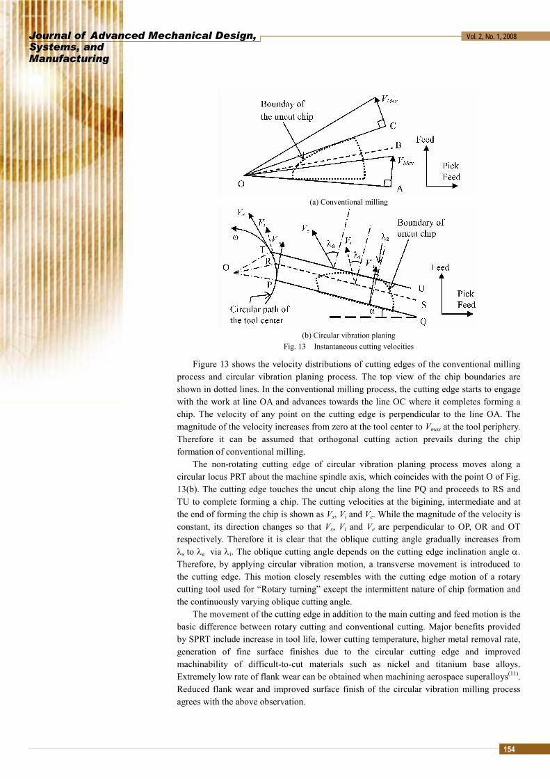
(b) Circular vibration planing Fig. 13 Instantaneous cutting velocities
Figure 13 shows the velocity distributions of cutting edges of the conventional milling process and circular vibration planing process. The top view of the chip boundaries are shown in dotted lines. In the conventional milling process, the cutting edge starts to engage with the work at line OA and advances towards the line OC where it completes forming a chip. The velocity of any point on the cutting edge is perpendicular to the line OA. The magnitude of the velocity increases from zero at the tool center to Vmax at the tool periphery. Therefore it can be assumed that orthogonal cutting action prevails during the chip formation of conventional milling.
The non-rotating cutting edge of circular vibration planing process moves along a circular locus PRT about the machine spindle axis, which coincides with the point O of Fig. 13(b). The cutting edge touches the uncut chip along the line PQ and proceeds to RS and TU to complete forming a chip. The cutting velocities at the bigining, intermediate and at the end of forming the chip is shown as Vs, Vi and Ve. While the magnitude of the velocity is constant, its direction changes so that Vs, Vi and Ve are perpendicular to OP, OR and OT respectively. Therefore it is clear that the oblique cutting angle gradually increases from λs to λe via λi. The oblique cutting angle depends on the cutting edge inclination angle α. Therefore, by applying circular vibration motion, a transverse movement is introduced to the cutting edge. This motion closely resembles with the cutting edge motion of a rotary cutting tool used for “Rotary turning” except the intermittent nature of chip formation and the continuously varying oblique cutting angle.
The movement of the cutting edge in addition to the main cutting and feed motion is the basic difference between rotary cutting and conventional cutting. Major benefits provided by SPRT include increase in tool life, lower cutting temperature, higher metal removal rate, generation of fine surface finishes due to the circular cutting edge and improved machinability of difficult-to-cut materials such as nickel and titanium base alloys. Extremely low rate of flank wear can be obtained when machining aerospace superalloys(11). Reduced flank wear and improved surface finish of the circular vibration milling process agrees with the above observation.

Journal of Advanced Mechanical Design,Systems, and Manufacturing
Vol. 2, No. 1, 2008
155
5. Conclusions
The ability of the circular vibration planing process to produce better finished surfaces on Inconel 718 at a four fold increase of tool life was proven, compared with conventional milling process.
• Inclination angle of the cutting edge with respect to feed direction has an effect on the finished surface roughness. Experimental results showed that the surface roughness was minimum when the cutting edge angle was set around 10o.
• Uniform and reduced tool flank face wear was observed in the circular vibration planing, compared with the conventional milling.
• For a given spindle speed and tool inclination angle, the cutting speed of circular vibration planing is lower than that of the conventional ball end milling.
• Commercially available tools having common cutting edge geometries could be used for circular vibration planing, where as custom made tools were needed for circular vibration milling.
Acknowledgement
This research was supported by Grant-in Aid for Scientific Research (No. 16360071) of the Japan Society for the Promotion of Science (JSPS). Machine Tool Technologies Research Foundation (MTTRF) of the USA granted the five axis milling machine (Mori Seiki’s GV4000/5AX) which was used for conventional milling and circular vibration milling experiments of this research, under the foundation’s equipment loan award program.
References
(1) Shamoto, E. and Moriwaki, T., Study on Elliptical Vibration Cutting, Annals of the CIRP, Vol. 43, No.1, 1994, pp.35-38.
(2) Shamoto, E., Morimoto, Y., and Moriwaki, T., Elliptical Vibration Cutting (1st Report) -Cutting Principle and Basic Performance, J. JSPE, Vol. 62, No. 8, 1996, pp.1127-1131 (in Japanese).
(3) Shamoto, E., Ma, C. and Moriwaki, T., Elliptical Vibration Cutting (3rd Report) -Application to Three Dimensional Cutting and Investigation of Practical Effects, J. JSPE, Vol. 65, No. 4, 1999, pp.586-591(in Japanese).
(4) Shamoto, E. and Moriwaki, T., Ultra precision Diamond Cutting of Hardened Steel by Applying Elliptical Vibration Cutting, Annals of CIRP, Vol. 48, No. 1, 1999, pp.441-444.
(5) Alauddin, M., Mazid M.A., El Baradi M.A. and Hashmi M.S.J. Cutting forces in the end milling of Inconel 718, J. of Materials Processing Technology, Vol. 77, 1998, pp.153-159
(6) Ezugwu, E. O., Wang, Z. M. and Machado, A. R., The Machinability of nickel-based alloys: a review, Journal of Materials Processing Technology, Vol. 86: 1999, pp.1-16.
(7) Hettiarachchi, N., Moriwaki T., Nakamoto K., Saraie H. and Mochizuki A., Surface Finish Improvement in Machining of Inconel 718 by Circular Vibration Ball End Milling, Proceedings of the 8th Int. conference on Progress of Machining Technology (ICPMT 2006), 2006, pp.105-108.
(8) Moriwaki, T., Shamoto E., Song Y. C. and Kohda S., Development of an Elliptical Vibration Milling Machine, Annals of CIRP, Vol. 53, No. 1, 2004, pp.341-344
(9) Hettiarachchi, N., Moriwaki T., Nakamoto K., Saraie H. and Mochizuki A., Development of a circular vibration milling attachment and its application to machining of hardened steels, Int J. of Manufacturing research, Vol. 1, No. 3, 2006, pp.300-313.
(10) Jindal, P. C., Santhanam A. T., Schleinkofer U. and Shuster A. F., Performance of PVD TiN, TiCN and TiAlN coated cemented carbide tools in turning, Int J. of Refractory Metals and Hard Materials, Vol. 17, 1999, pp.163-170
(11) Ezugwu, E.O., Journal of Materials Processing Technology, Vol. 185, 2007, pp.60-71.