jøtul f 602 cb - tall pines farm stoves & fireplacess manual/139677... · jøtul f 602 cb...
TRANSCRIPT

Jøtul F 602 CBNon-catalytic Wood Heater
Installation and Operating Instructions for the U.S. & Canada
Save this manual and make it available to anyone using or servicing the stove.
Jøtul F 602 CB

2
F 602 CB 139677_R01 May 2015
StandardsThe Jøtul F 602 CB solid fuel heater has been tested and listed to U.S. Standards: ANSI/UL 737 and ANSI/UL 1482. Canadian Standards: CAN/ULC-S627-M00 and CAN/ULC-S628-M93
Tests performed by: Intertek Testing Services, Middleton, Wisconsin U.S.A.
Manufactured by:Jøtul North America, Inc.55 Hutcherson DriveGorham, Maine 04038, USAand Jøtul AS, P.O. Box 1411, Fredrikstad, Norway
Installation and Operation Instructions for USA/Canada
Safety Notice: If this solid fuel room heater is not properly installed, a house fire may result. For your safety, follow the installation directions. Contact local building or fire officials about restrictions and installation inspection requirements in your area.
This manual describes the installation and operation of the Jøtul F 602 CB non-catalytic wood heater. Read this entire manual before you install and use your new stove. Save these instructions for future reference.
This wood heater needs periodic inspection and repair for proper operation. See this manual for specific information. It is against federal regulations to operate this wood heater in a manner inconsistent with the operating instructions in this owner’s manual.
Check Building CodesWhen installing, operating and maintaining your Jøtul F 602 CB woodstove, follow the guidelines presented in these instructions, and make them available to anyone using or servicing the stove.
Your city, town, county or province may require a building permit to install a solid fuel burning appliance.
In the U.S., the National Fire Protection Association’s Code, NFPA 211, Standards for Chimneys, Fireplaces, Vents and Solid Fuel Burning Appliances, or similar regulations, may apply to the installation of a solid fuel burning appliance in your area.
In Canada, the guideline is established by the CSA Standard, CAN/CSA-B365-M93, Installation Code for Solid-Fuel-Burning Appliances and Equipment.
Always consult your local building inspector or authority having jurisdiction to determine what regulations apply in your area.
THE JØTUL F 602 CB IS NOT APPROVED FOR USE IN MOBILE HOMES.
HIGH HEAT LOW HEAT VALUE VALUE Efficiency:* 70.7% 76.4% CO Emissions:* 64.6 g/hr Pariculate Emissions: 3.4 g/hr * Per CSA B415.1-10
See OPERATION Sect. 5.0 of this manual for important information regarding the safe, proper, and most efficient operation of your stove.
This heater meets the 2015 U.S. Environmental Protection Agency’s emission limits for wood heaters manufactured after May 15, 2015. This heater may not to be sold after May 15, 2020.
Combustion Specifications
WARNING !THIS WOOD HEATER HAS A MANUFACTURER-SET MINIMUM LOW BURN RATE THAT MUST NOT BE ALTERED. IT IS AGAINST FEDERAL REGULATIONS TO ALTER THIS SETTING OR OTHERWISE OPERATE THIS WOOD HEATER IN A MANNER INCONSISTENT WITH OPERATING INSTRUCTIONS IN THIS MANUAL.
Heat Output: Under specific test conditions, this heater has been shown to deliver heat ranging from 11,998 to 47,713 BTU’s.

3
F 602 CB 139677_R01 May 2015
1.0 Safety Notices • BURN SOLID, NATURAL WOOD FUEL ONLY. DO NOT BURN
ANY OTHER FUEL.• DO NOT USE CHEMICALS OR FLUIDS TO START A FIRE. DO
NOT BURN GARBAGE OR FLAMABLE FUELS.• DO NOT USE A GRATE OR ELEVATE THE FIRE. BUILD THE
FIRE DIRECTLY ON THE HEARTH.• IF THIS ROOM HEATER IS NOT PROPERLY INSTALLED, A
HOUSE FIRE MAY RESULT. TO REDUCE THE RISK OF FIRE, FOLLOW THE INSTRUCTIONS IN THIS MANUAL. FAILURE TOFOLLOW THESE INSTRUCTIONS MAY RESULT IN PROPERTYDAMAGE, BODILY INJURY, OR LOSS OF LIFE.
• CONTACT LOCAL BUILDING OR FIRE OFFICIALS ABOUTRESTRICTIONS AND INSTALLATION INSPECTIONREQUIREMENTS IN YOUR AREA.
• ANY EXISTING CHIMNEY SYSTEM MUST BE INSPECTEDBEFORE INSTALLATION OF THIS APPLIANCE.
• DO NOT CONNECT THIS STOVE TO ANY AIR DISTRIBUTIONDUCT OR SYSTEM.
• EXTREMELY HOT WHILE IN OPERATION! KEEP CHILDREN, CLOTHING, AND FURNITURE AWAY. CONTACT WILL CAUSESKIN BURNS. USE A CHILD GUARD SCREEN TO PREVENTACCIDENTAL CONTACT BY SMALL CHILDREN.
• INSTALL SMOKE DETECTORS IN THE LIVING AREA ANDBEDROOMS OF YOUR HOME. TEST THEM REGULARLY ANDINSTALL FRESH BATTERIES TWICE ANNUALLY.WHEN INSTALLED IN THE SAME ROOM AS THE STOVE, A SMOKE OR CARBON MONOXIDE DETECTOR SHOULDBE LOCATED AS FAR FROM THE STOVE AS POSSIBLE TOPREVENT THE ALARM SOUNDING WHEN ADDING FUEL.
• DO NOT OPERATE THIS APPLIANCE WITH CRACKED ORBROKEN GLASS. REPLACE GLASS ONLY WITH JØTUL PARTNUMBER 128101.
• Avoid creating a low pressure condition in the roomwhere the stove is operating. Be aware that operationof an exhaust fan or clothes dryer can create a lowpressure area and consequently promote flow reversalthrough the stove and chimney system. In some cases, the optional Fresh Air Adaptor #156408 can be usedto alleviate this condition. The chimney and building, however, always work together as a system - provisionof outside air, directly or indirectly to an atmosphericallyvented appliance will not guarantee proper chimneyperformance. Consult your local Jøtul authorized dealerregarding specific installation/performance issues.
• Jøtul strongly recommends that this stove be installed by aprofessional solid fuel technician, or that you consult oneif you do the work yourself. Also, consult your insurancecompany regarding any other specific requirements.
Table of Contents1.0 Safety Notices ................................................................3
2.0 Initial Assembly2.1 Inspect Contents ................................................................... 42.2 Flue Collar Reversal .............................................................. 4
3.0 Installation3.1 Chimney Connection .......................................................... 43.2 Wall Pass-throughs .............................................................. 43.3 Chimneys ................................................................................ 53.4 Hearthmount / Fireplaces .................................................. 53.5 Prefabricated Chimneys ...................................................... 5
4.0 Clearances to Combustibles4.1 Floor Protection ..................................................................... 64.2 Clearances to Walls and Ceilings ...................................... 64.3 Using Shields to Reduce Clearances ............................... 64.4 Alcove Installation ............................................................... 6
6.0 Operation6.1 Combustion Efficiency......................................................... 76.2 CO Emissions ......................................................................... 76.3 Wood Fuel and Performance ............................................. 76.4 Air Flow and Control ............................................................ 76.5 Break-in Procedure ............................................................... 86.6 Starting / Maintaining the Fire ......................................... 86.7 Adding Fuel ............................................................................ 96.8 Ash Removal........................................................................... 9
7.0 Maintenance7.2 Glass Care ............................................................................... 97.3 Glass Removal ....................................................................... 9
8.0 General Maintenance8.1 Gaskets .................................................................................... 108.2 Gasket replacement ............................................................. 108.3 Chimney System ................................................................... 10
10.0 Illustrations10.1 Clearance Chart ................................................................... 1110.2 Stove Dimensions ............................................................... 1210.2 Chimney Requirements .................................................... 1210.2 Hearth Protection ............................................................... 1310.2 Clearance Diagrams ........................................................... 14-1510.2 Parts Diagram and List ....................................................... 16-17
11.0 Appendix A - Alternate Floor Protection ...................... 17
12.0 Warranty .............................................................................. 18

4
F 602 CB 139677_R01 May 2015
2.0 Initial Assembly2.1 Inspect ContentsInspect the stove for damage. Contact your dealer immediately if any damage is found. Do not install the stove if any damage is evident.
Contents: • Door Knob Kit• Flue Collar Adaptor• Flue Collar• Hardware Kit
2.2 Flue Collar PositionThe Flue Collar may be installed in either a top-exit or rear-exit position. For Top Exit, use the pre-installed screws to secure the flue collar to the top plate. For Rear Exit, first remove the screws and 10mm nuts that attach the rear cover plate to the back plate. Reach throught the top outlet to access the nuts. Use these same fasteners to attach the flue collar to the stove. Secure the cover plate to the top plate using the pre-installed screws.
3.0 Installation A safe stove installation includes several elements: 1) the chimney connector2) the chimney itself3) the connection between the chimney connector andchimney, and 4) protection of combustible materials in the vicinity ofthe stove. Each of these elements is equally important for a safe stove installation.
3.1 Chimney Connector (Stove Pipe)Use 6” single wall or listed 6” double-wall stovepipe to connect the stove to the chimney. Single wall stovepipe must be black iron or stainless steel and have a minimum thickness of 24 gauge. Do not use aluminum or galvanized steel pipe for chimney connection - these materials are not suitable for use with solid fuel.
• DO NOT USE CHIMNEY CONNECTOR AS A CHIMNEY. IT ISINTENDED ONLY TO BE USED A CONNECION DEVICE.
• Each connector section must be oriented with the male(crimped) end pointing toward the stove. See fig. 2, page 12.
• Secure all connector joints with three sheet metal screws.• For the best performance, the chimney connector should be as
short and direct as possible, including no more than two 90°elbows.
• The maximum vertical run of single wall stovepipe should notexceed 10 ft. (305 cm). The maximum horizontal run should notexceed 3 ft. (92 cm) with a 1/4” rise per foot.
• No part of the chimney connector may pass through an atticor roof space, closet or other concealed space, or through afloor or ceiling. All sections of the chimney connectors must
be accessible for cleaning. Where passage through a wall or partition of combustible construction is desired, the installation must conform with NFPA 211 or CAN/CSA-B365, and is also addressed in this manual.
• DO NOT CONNECT THIS HEATER TO ANY CHIMNEY SERVICING ANOTHER APPLIANCE.
3.2 Wall Pass-Throughs
In the U.S.The National Fire Protection Association’s publication, NFPA 211, Standard for Chimneys, Fireplaces, Vents and Solid Fuel Burning Appliances permits four methods for passing through a combustible wall. Before proceeding with any method be sure to consult with your local building officials to discuss any local code requirements.
Common Method / U.S. • See figures 3, page 12. Remove all combustible materials from
the pass-through area ( around the chimney connector), aminimum 12” (30.5 cm). A 6” (15.2 cm) diameter connector willrequire a 31” x 31” (78.7 x 78.7 cm) square opening.
• The opening must be filled with at least 12” (30.5 cm) ofbrick around a fireclay liner. The liner must be ASTM C35 orequivalent, having a minimum wall thickness of 5/8” (16 mm).
• The Pass-through must be at least 18” (45.7 cm) fromcombustible ceiling materials.
• It will be necessary to cut wall studs, install headers, andconstruct a sill frame to maintain the proper dimensions andto support the weight of the brick.
• The bricks must be solid brick with a minimum of 3 ½ inchesthick (nominal 4” / 102 mm).
• Refractory mortar must be used at the junction of the chimney and the pass-through liner. The pass-through liner must notpenetrate the chimney liner beyond the inner surface of thechimney liner. Use extreme care when constructing the holein the chimney liner as the tiles can shatter easily.
In Canada The installation must conform to CAN/CSA-B365, Installation Code for Solid Fuel Burning Appliances and Equipment. Before proceeding be sure to consult your local building inspector.
Common Method / Canada• This method requires the removal of all combustible materials
from at least 18” (45.7 cm) around the chimney connector’sproposed location. A 6” round liner requires a minimumopening 43” x 43” (109.2 x 109.2) square.
• Locate the pass-through at least 18” from combustible ceilingmaterials.
• The space that is cleared of combustible materials must remainempty. Sheet metal panels can be used to cover the area.However, when using a panel on both sides of the wall, eachcover must be installed on noncombustible spacers at least 1” from the wall. If one panel of sheet metal is to be used it maybe installed flush to the wall.
See section 5.3.1 and 5.3.2 of CAN/CSA - B365-M91. Consult your local building inspector, authorized Jøtul Dealer, NFPA 211 in the U.S. or CAN/CSA-B635 in Canada for other approved wall pass-through methods.

5
F 602 CB 139677_R01 May 2015
A chimney, wether masonry or prefabricated metal, must be the required height above the roof or other obstruction for safety and for proper draft operation. The requirement is that the chimney must at least 3’ higher than the highest point where it passes through the roof and at least 2’ higher than the be at least and highest part of the roof or structure that is within 10’ of the chimney, measured horizontally. See fig. 4, page 12.
Chimneys shorter than 15 feet may not provide adequate draft. This can result in smoke spilling the room from the door or joints in the stove or pipe. In addition, inadequate draft can cause back-puffing. Overly-strong draft, on the other hand, causes excessive temperatures and can shorten burn times. lf you suspect you have draft problem, consult your dealer.
When connecting to a masonry chimney, the chimney connector must slide completely inside the chimney thimble (or breach) to the inner surface of flue liner, make sure the connector does not protrude past the inside of the flue liner as that will reduce the flow area available for the smoke and ultimately cause problems with your chimney system. The chimney connector should be sealed into the thimble with refractory cement and the connector should also be mechanically fastened to the chimney. See fig. 6, page 13.
3.4 Hearthmount into a Masonry FireplaceThe Jøtul F 602 CB may be installed into a masonry fireplace provided the height of the opening is a minimum of 29 1/2”. Use of the Short Leg Package will reduce the stove height by 2 1/4” (57 mm).
Building code requires that the fireplace damper plate be removed or securely fixed in the open position. A connector pipe must then extend from the stove’s flue exit through the damper area of the fireplace and into the chimney tile liner. The inside area of the flue liner must not be less than the area of the stove flue collar and cannot be more than three times greater than the cross sectional area of the stove flue collar.
If the chimney liner is too large to accommodate the stove, an approved relining system must be installed to resize the flue.A new sheet metal damper block-off plate must be installed around the connector pipe at the damper frame and sealed with the proper sealant (usually High-Temp Silicone).
3.5 Listed Metal Prefabricated ChimneyThe heater must be connected to a listed Type HT per UL 103 or ULC S629 prefabricated chimney. When a metal prefabricated chimney is used, the manufacturer’s installation instructions must be followed precisely. You must also purchase (from the same manufacturer) and install the ceiling support package or wall pass through, the “T” section package, the firestops (when needed), the insulation shield, the roof flashing, the chimney cap, etc. Maintain all clearances to the structure as recommended by the manufacturer. This clearance is usually a minimum of 2”, although it may vary by manufacturer or for certain components.See fig. 5, page 13.
3.3 ChimneysThere are two types of chimneys suitable for the Jøtul F 602 CB: 1. A code-approved masonry chimney with a ceramic tile or listed
steel flue liner.2. A prefabricated chimney complying with the requirements for
Type HT (2100°F) chimneys per UL 103 or ULC S629.
The minimum chimney height is 15 feet (4.57 m).
When selecting a chimney type and the location for the chimney in the house, keep this in mind: it is the chimney that makes the stove work, not the stove that makes the chimney work. This is because a chimney actually creates suction, called draft, which pulls air through the stove.
Several factors affect draft: the height, cross-sectional area, and temperature of the chimney, as well as the proximity of surrounding trees or buildings.
In general, a short prefabricated chimney on the exterior of the house will give the poorest performance. This is because it can be very difficult to warm up from a cold start and maintain effective draft.
A centrally-located, interior masonry chimney will be easier to keep warm and will perform well under a variety of conditions.
This guideline gives the necessary chimney requirements based on the U.S. national code (NFPA-211). However, many local codes differ from the national code to take into account climate, altitude, or other factors. It is important that you check with your local building officials to find out what codes apply in your area before constructing a chimney.
Masonry ChimneysThe minimum requirements for a properly constructed chimney include the following:• The foundation must be large enough to support the intended
chimney without settling.• The masonry wall of the chimney, if brick or modular
block, must be a minimum of 4” nominal thickness. A mountain- or rubble-stone wall must be at least 12” thick.
• The chimney must have a fireclay flue liner (or equivalentwith a minimum thickness of 5/8” and must be installed with refractory mortar. There must be at least 1/2” air space between the flue liner and chimney wall.
• The preferred fireclay flue liner size has a nominal size of 8” x8”, and should not be larger than 8” x12”. lf round fireclay liners are used, the inside diameter should be 6” and not larger than 8”. lf an existing chimney with larger tiles is used it should be relined with an appropriate liner.
• No other appliance can be vented into the same flue. • An airtight cleanout door should be located at the base of the
chimney.
A chimney inside the house must have at least 2” of clearance to the combustible structure. A chimney outside the house must have at least 1” clearance to the combustible structure. Fire stops must be installed at the spaces where the chimney passes through floors and/or ceilings. Remember that there must be air space around the chimney, and that insulation must be 2” or more from the chimney.

6
F 602 CB 139677_R01 May 2015
4.0 Clearances to Combustibles4.1 Floor ProtectionA bottom heat shield is required in all installations. In addition, the stove must be placed on a noncombustible surface that extends 8” beyond the sides and back of the stove and 16” in the front of the stove. This will result in an overall base that is 28 1/2” wide x 45- 1/2” deep . This is the minimum floor protector size. Floor protection must also be used under the stove pipe and must extend 2” beyond either side of the pipe (fig. 7, page 13).
The floor protection must have a minimum R value of 0.45.Warning! Never put any type of floor protection on top of carpeting.
4.2 Alternate Floor ProtectionAll floor protection materials must be non-combustible (i.e., metals, brick, stone, mineral fiber boards, etc.). Any organic materials (i.e., plastics, wood, paper products, etc.) are combustible and must not be used. The floor protector specified may include some form of thermal designation such as R-value (thermal resistance), k-factor (thermal conductivity), or C-factor (thermal conductance).
See 8.0 Appendix A on page 17 for the procedure to determine alternate floor protection materials that meet the thermal requirements for this stove.
4.3 Clearance to Adjacent Combustible MaterialsThe diagrams in figures 8-11, pages 13, give the required clearances that must be maintained from unprotected combustible materials or objects.
A combustible material is anything that can burn, and in the case of stove installations, these material may not be visible. lf you are not sure of the combustible nature of any material in the vicinity of your planned stove installation, you should check with your local fire off icials. Remember that “fire resistant” materials are considered combustible; they are difficult to ignite, but they will burn.
lf you have recently purchased a home that has a stove hearth in it that you plan to use, it is extremely important that the entire system be examined for safety. Many older homes may have faulty chimneys, or previous owners may have covered combustible walls or studs with brick veneers. Heat is conducted readily through brick and could ignite combustible materials hidden behind it.
Contact local building or fire official about restrictions and installation requirements in your area.
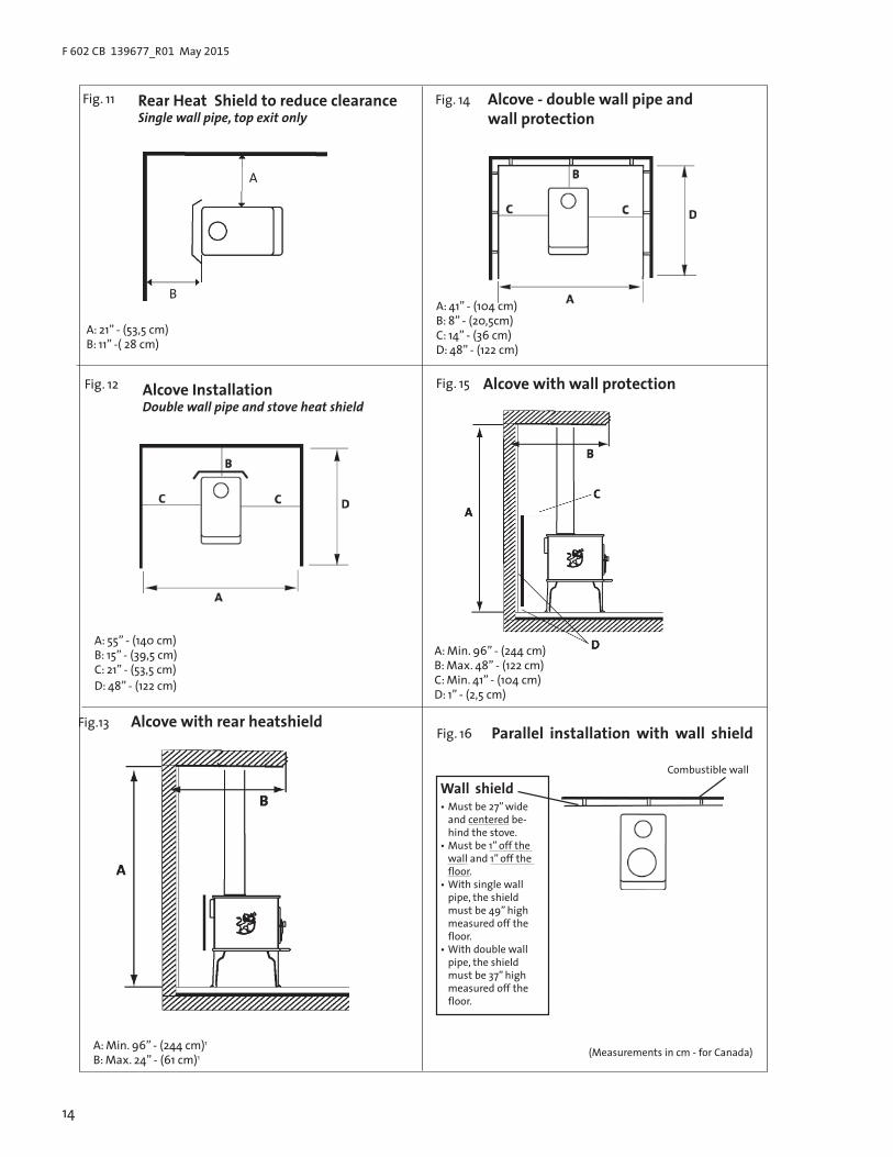
4.4 Using a Rear Heat Shield to Reduce Clearance The Jøtul F 602 CB optional rear heat shield, PN HS50,may be used only in top-exiting parallel installations to reduce clearance as shown in figures 11,12,13, page 14.
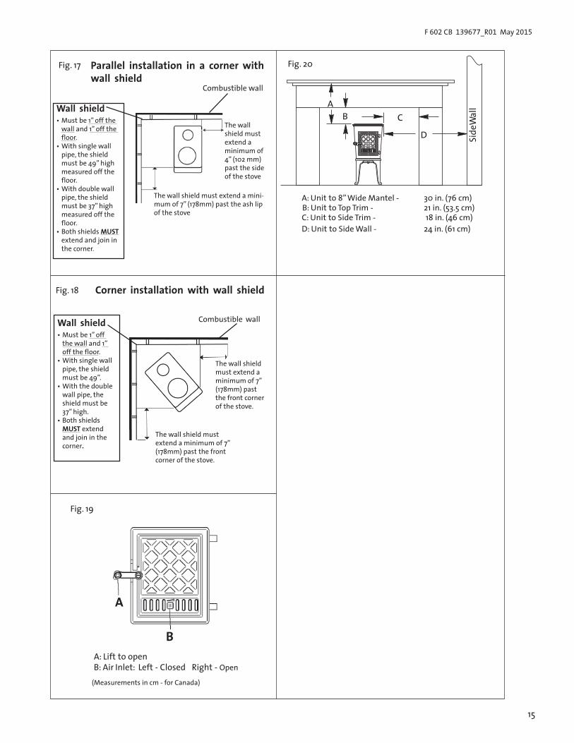
4.5 Using Wall Protectors to Reduce ClearancesThe wall protector must be non-combustible, such as a minimum 24 gauge galvanized steel or its equivalent. The wall protector must be elevated 1” from the floor to provide an air space of at least 1” between the shield and the combustible wall. See figures 16, 17, and 18 on pages 16-17 for approved sizing specifications.
4.6 Alcove installationWhen installed with a listed double wall pipe and with wall protection, the Jøtul F 602 CB can be placed in an alcove that has a minimum height of 96”1 and a maximum depth of 48”, and a minimum width of 41”. See fig. 15, page 16.
When installed with a listed double wall pipe and with a stove heat shield, the Jøtul F 602 CB can be placed in an alcove that has a minimum height of 96”1 and a maximum depth of 24”2, and a minimum width of 55”. The clearances for this installation are shown in fig. 15 page 16.
4.6 Alcove installationIn an alcove, the height of the wall protector, including the air space at the bottom, must be at least 41” (104 cm). See fig. 15, page 16. Both side walls and the rear wall must be protected by the wall protector. See fig. 14, page 16.
4.7 Fireplace ClearancesFor a fireplace installation, refer to the clearance specifications as shown in fig. 20, page 17.

7
F 602 CB 139677_R01 May 2015
5.0 OperationPlease read the following section completely before building a fire in your new Jøtul F 602 CB.
5.1 Combustion EfficiencyEPA qualified tested efficiency values are not currently available for the Jøtul F 602 CB. The EPA default efficiency for non-catalytic wood heaters is 63% per Federal Register 40 CFR Part 60, Subpart AAA.
There are, however, aspects of efficiency that you should be aware of in order to get the most from your stove. Operation habits and fuel moisture can have a significant effect on efficiency. Poorly seasoned wood having a higher than optimum moisture content, can reduce the amount of energy transferred tothe living area as a result of the energy expended to evaporate the excess fuel moisture in order for the wood to burn. Operational aspects, such as not building a robust kindling fire to readily ignite the larger fuel pieces, can result in an inefficient smoldering fire. Additionally, most modern wood heaters’ optimum performance and efficiency are at the medium to medium -low burn rates.
The location of the stove can have a significant effect on heating efficiency, primarily in regard to distribution of the heat. Ror example, a wood heater centrally located in the residence in an open living area will likely provide better circulation of heat than will a stove located in a room adjacent to the larger living area.
5.2 CO EmissionsEPA qualified tested carbon monoxide (CO) values ar not currently available for the Jøtul F 602 CB. There are, however, aspects of CO that you should know. Most all means of combustion produce CO, including wood fires. Maintaining a well-established fire and avoiding operation that produces a smoldering, smoky fire, will greatly reduce CO levels.
It is highly recommended that a CO monitor (detector) be installed in the same room as the stove. The monitor, however, should be located as far away as possible from the stove to avoid alert soundings when adding fuel to the fire.
5.3 Wood Fuel and PerformanceThe F 602 CB is designed to burn natural wood only. Higher efficiencies and lower emissions generally result when burning air-dried, seasoned hardwoods, as opposed to softwoods, green or freshly cut hardwoods. Wood that has been air-dried for a period of 6 to 14 months will provide the cleanest, most efficient heat. Wood seasoned more than 2 years will burn too quickly to take advantage of the stove’s low end efficiency strength.
A seasoned log will have check marks on the ends and be lighter than an unseasoned log which will show little or no check marks.
Cordwood should be stacked to allow the free flow of air circulation necessary to promote the seasoning process. Securely cover the stack to ensure it remains as dry as possible.
Check Moisture Content We recommed using a moisture meter to determine the moisture content of your wood. For purposes of home heating, your fuel should have a moisture content between 12 - 20%. Wood with higher moisture content will burn, however, very inefficiently. Most of its heat value will be lost to driving water out of the wood. Worse, that moisture will condense as creosote in the relatively cool chimney flue, increasing the potential for a chimney fire. Use of unseasoned wood defeats the purpose of any modern wood-burning stove.
DO NOT BURN:• Coal;• Garbage;• Synthetic fuel or logs;• Material containg rubber, including tires;• Material containing plastics;• Waste petroleum products, asphalt products, paints,
paint thinners or solvents;• Materials containing asbestos;• Construction or demolitioin debris;• Railroad ties or pressure-treated wood;• Manure or animal remains;• Salt water driftwood or other previously salt-water;
saturated materials;• Unseasoned wood; or• Paper products, cardboard, plywood, or particle board. (Theprohibition against burning these materials does not prohibit the use of fire starters made from paper, cardboard, saw dust, wax or similar substances for the purpose of starting a fire.)
The burning of any of these materials can result in the release of toxic fumes, or render the heater ineffective and cause smoke.Never use gasoline, gasoline-type lantern fuel, kerosene, charcoal lighter fluid, or similar liquids to start or “freshen-up” the fire. Always keep such liquids away from the heater at all times.
NOTE: Avoid letting logs rest directly on the glass panel. The logs should be spaced off of the glass enough to allow for proper air flow within the firebox.
5.4 Air Flow and ControlYour Jøtul F 602 CB is designed to support efficient combustion and heat transfer by directing air through the stove in two separate channels; Primary and Secondary.
Primary air is manually regulated by a sliding valve located in the load door. The valve position controls the volume of primary air entering the firebox and thereby affects fire intensity, heat output and burn time. Primary air is directed to the main body of the fire through that air inlet.
Secondary air allows combustion of volatile gas and other by-products of primary combustion that would otherwise enter the atmosphere unburned. This unregulated air is preheated as it passes through a manifold at the back of the stove and is then directed to the fire through a stainless steel manifold at the top of the firebox. This additional hot oxygen allows any unburned gasses to be burned inside the stove. The action of secondary combustion can be readily seen through

8
F 602 CB 139677_R01 May 2015
5.6 Building a FireA good fire will efficiently utilize your fuel, keep the glass in the door clean, keep emissions and creosote to an absolute minimum, require less work, and be very predictable.
• Set the air control lever fully to the right. Open the frontdoor and cover the bottom of the stove with tightlycrupled newspaper. Criss-cross a generous double handful of dry kindling, such as split pieces of scrap lumber, ontop of the paper. Place three or four 1 “ -2” split pieces of dry wood on top of the kindling.
• Light the paper evenly across the front and close the door.• Continue to add 1” - 2” pieces of split dry wood until a
healthy bed of glowing coals has formed.• You can now add three or four small-to-medium pieces
of wood. Allow this wood to burn for several minutes.Once you are sure the wood is burning well, adjust the air control to your desired heat output level. Avoid operating the stove with the air control closed completely.
• In order for secondary combustion to occur, the fire mustbe well established with temperatures above 1.0000F(6000C) in the firebox.
• lf the fire dies out, the cause is most likely either aninsufficient bed of coals, reducing the air supply too soon, or using wood that is either too large or not dry enough.
5.7 ReloadingReload the stove while it is still hot and there are plenty of hot to ignite the fresh fuel load. It is a good idea to include a smaller piece or two of wood at the base of the new load to help the stove recover more quickly to its operating temperature.
Reloading Procedure• Always wear gloves when tending your stove. • Push the air control to the right to the full open position.• Wait a few seconds and open the door. • Use a stove shovel or similar tool to break up any
remaining charcoal and to drag some live embers towardthe front where combustion air enters.
• Load the fuel (Smaller pieces first).• Close the door.• Wait 5-10 minutes and adjust the air control to desired
setting.
Note: lf the charcoal bed present at reloading time is relatively deep (2”-3”) and your wood is well seasoned, it is possible to add the fresh fuel load, close the door and reset the air control for the desired heat output rate within 5 minutes.
WARNING: DO NOT OVERFIRE THIS HEATER. IF ANY PART OF THE STOVE OR CHIMNEY CONNECTOR GLOWS, YOU ARE OVERFIRING. A HOUSE FIRE OR SERIOUS DAMAGE TO THE STOVE OR CHIMNEY COULD RESULT.
the viewing glass a slow, rolling flames suspended over the main fuel bed and smaller jets of flame extending from the secondary manifold ports. At the same time, no smoke will be observed exiting the chimney. This is evidence that the stove is operating at the so-called ”sweet-spot” wherein optimum efficiency is realized.
When first starting or reviving the fire: the primary control lever should be set to the far right position, which permits the maximum amount of air into the stove. The greater the amount of air entering the stove, the hotter and faster the fire will burn. Moving the lever to the left reduces the airflow into the stove which prolongs the fire at a lower heat output. See figure 19.
Using a Stove-top ThermometerDetermining the primary air setting for the best overall performance for your particular needs and installation will be established over time through trial and error. Each installation has unique characteristics that will affect stove performance. You should use a stove-top thermometer to monitor the status of the fire. Once the temperature has reached 400°F - 600°F, set the air control to a mid-range position to allow adequate oxygen to support efficient combustion throughout the burn cycle.
5.5 New Stove Break-In ProcedureThe Jøtul F 400 CB is constructed of cast iron and stove furnace cement. Cast iron, while very durable, expands and contracts as it is heated and cooled. This type of construction requires the stove to be “broken-in” gradually so that thermal expansion does not occur too quickly. The following steps describe the proper break-in procedure for the Jøtul F 400 CB:1. Light a small fire of newspaper and kindling. Only allow the
stove to reach a maximum surface temperature of 200°F (93° C). Burn for approximately 1 hour.
2. Allow the stove to cool to room temperature.3. Light a second fire, allowing the stove to reach a maximum
temperature of 300°F (149°C) for 1 hour.4. Cool the stove to room temperature.5. Light a third fire and gradually allow the stove to reach a surface
temperature of 400°F (204°C).6. Cool stove to room temperature. This completes the “break-in”
procedure.
Note: Keep the stove under 400°F (204°C) surface temperature during any “break-in fire”, with the exception of the last “break-in” fire. If the temperature exceeds 400°F, move the primary air control lever all the way to the left to shut off the air supply completely. It is normal that the stove top temperature will continue to climb until the fuel burns down somewhat. Once the fire is out and the stove has cooled to room temperature, continue the break-in procedure. Never attempt to reduce the temperature by removing burning logs from the fire.
NOTE: It is normal for a new painted stove to emit an odor and smoke during its first several fires. This is caused by the seasoning of the high temperature paint and will diminish with each fire. Opening a window or door to provide additional ventilation will alleviate this condition.

9
F 602 CB 139677_R01 May 2015
ATTEMPTS TO ACHIEVE HEAT OUTPUT RATES THAT EXCEED HEATER DESIGN SPECIFICATIONS CAN RESULT IN PERMANENT DAMAGE TO THE HEATER.
Creosote and Soot Formation and the Need for RemovalWhen wood is burned slowly, it produces tar and other organic vapors which combine with expelled moisture to form creosote. These creosote vapors condense in the relatively cool chimney flue of a slow burning fire. The creosote that accumulates in the flue is highly flammable and is the fuel of chimney fires. To prevent a chimney fire, the creosote needs to be removed by sweeping the chimney and flue connector. The frequency of sweeping will depend on how you operate your stove. An accumulation of 1/4” or more on the sides of the flue or connector is considered hazardous and should be removed.
In the event that creosote in your chimney or flue connector ignites, the resulting fire is often accompanied by a roaring noise and a crackling sound as flakes of burned creosote break loose. lf you suspect you are having a chimney fire, immediately close the primary air control and make sure the stove door is closed. Call the fire department and get everyone safely out of the house.
Trying to extinguish the fire in the stove will not help. In fact it can make the matter worse by allowing more oxygen through the door, which then accellerates the fire in the chimney. When the roaring and crackling has stopped, you should resist the temptation to open the door and look at the fire. The fire may have suffocated, but could rekindle when you open the door. After a chimney fire, do not use your stove until the chimney and the flue connector has been cleaned and inspected to ensure that no damage has occured.
5.8 Open Door Fire-viewingWarning: This stove should be operated with the door either fully open with the optional Spark Screen in place, or with the door fully closed.If the door is left partly open, there is risk of overfiring.Also, gas and flame may be drawn out of the fireplace stove opening, creating risks from both fire and smoke. Be aware that when operating with the door open, there exists the possibility of generating carbon monoxide by some fuels (e.g. charcoal), and the hazards of carbon monoxide. Be sure adequate fresh air and ventilation is available to the stove.
5.9 Ash RemovalAlways use stove gloves when handling hot ashes. Ash removal will be required every day or two during normal operation, and is most easily done when the fire has burned down to coals. Use a shovel to push or rake any hot coals first to one side. Shovel out the exposed ash, and push or rake the hot coal to the other side. Remove the ash from the second side and then spread the hot coals evenly across the firebox. Wood may now be added to quickly start a new fire.
6.0 Maintenance6.1 Glass CleaningFrom time to time, clean off the accumulated ash from the inside surfaces of the glass panels. lf this fly ash is allowed to remain on the surface for extended periods, it could eventually cause the glass to become permanently etched and somewhat cloudy. Any soot deposit on the glass will burn off during the next hot fire.
Never clean the glass while it is hot and never use any abrasive materials to clean the glass. Cool water and a soft cloth or paper towel are usually all that is required. Rinse thoroughly with clean water after washing and dry completely before burning your stove.
6.2 Glass and Gasket ReplacementTo prevent cracking of the glass operate the doors gently. Do not shut the door by striking or slamming.
NEVER OPERATE THE STOVE WITH CRACKED OR BROKEN GLASS. Replace the panel only with the correct Jøtul replacement glass, PN 128101. Do not use substitutes.
The glass can be replaced with the door still mounted to the stove or the door can be removed and placed on a flat working surface.
The replacement glass gasket is self-adeshive. Measure enough gasket to go from the upper right corner of the glass, down the right side, across the bottom and back up to the upper left corner and then add about 2-1/2”.
NOTE: THE TOP OF THE GLASS IS NOT GASKETED. This allows a small amount of air to enter through that area to help keep the glass clean.• Peel off about 10” of the self-adhesive backing strip.
Leaving about 1-1/4”of gasket “tail” overlapping, apply the gasket to the groove on the door, making sure that the adhesive is facing the door.
• Press the gasket firmly in place. • Peel off the remaining adhesive backing and apply the
remaining gasket, again leaving a “tail” at the upperleft corner.
• Press the gasket firmly in place. • Center the glass panel left and right on top of the
gasket. Slide the glass toward the bottom of the dooruntil it contacts the stops.
Ashes should be placed in a metal container used exclusively for ashes, with a tight fitting lid. The closed container of ashes should be placed outdoors, well away from all combustible materials, pending final disposal. lf ashes are disposed of by burisl in soil or otherwise dispersed, they should be retained in the closed container until all cinders have thoroughly cooled.

10
F 602 CB 139677_R01 May 2015
when used according to the guidelines in this manual. In order to maintain proper performance, you should inspect the chimney and chimney connector at the beginning of each heating season and then every other month during the heating season. Clean the chimney whenever creosote and fly ash accumulation exceeds 1/4 inch in any part of the system.
Chimney brushes are available from your local Jøtul dealer or hardware supply store. Your dealer can also refer you to a reputable, professional chimney sweep who will have all the equipment to ensure a complete and proper job. Failure to keep the chimney system free of creosote and build up could result in a chimney fire.
• Hold the glass in place with your hand and wrap thegasket “tails” over the top of the glass and down the outeredges. You will have to twist the gasket so the adhesivewill face the glass. Press the “tails” firmly on the glass.
• Replace the air control slide and the upper and lowerretainer manifolds and screws.
Glass retainers should be tightened gradually, following an alternating pattern similar to tightening the lug bolts on a vehicle wheel. Do not over-tighten. It may be necessary to retighten once again after the stove has been burned and the new gasket has seated.
6.3 Door GasketGaskets are a wear item which must be replaced ocassonally. To check the front door gasket, put a dollar bill halfway into the stove, close and latch the door, and try pulling the dollar out. lf it can be removed easily, the seal is too loose. Check several spots around the door. To replace the gasket, scrape out all old gasket material and gasket cement. Spread a 1/8” bead of stove cement into the bottom of the groove and press in new gasket.
Universal Gasket Kit 157050 includes all the gasket needed for replacement of the F 602 CB door and glass panel. The door requires 36” of 1/4” diameter high density gasket. The gasket between the glass panel and the door receives very little wear. The best indication that it needs to be replaced is streaks on the glass caused by air leaking around the sides of the glass.
6.4 GeneralAs with your car, regular maintenance will prolong the life of your stove and ensure satisfactory performance. A good time to do this is when you are cleaning the chimney and the connector. Thoroughly clean the entire stove. Brush all ash and soot out of the stove. It is better to brush out the ash and soot than to vacuum it out because soot particles are small enough to pass through most vacuum bags.
In a darkened room, use a strong light to inspect the stove inside and out for cracks or leaks at corners and joints. Cracked pants should be replaced. Leaks at joints can be patched with stove furnace cement.
6.5 Chimney CleaningThe Jøtul F 602 is designed to burn cleanly and efficiently
11
F 602 CB 139677_R01 May 2015
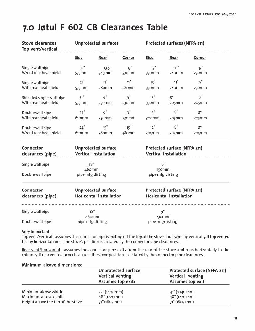
7.0 Jøtul F 602 CB Clearances TableUnprotected surfaces Protected surfaces (NFPA 211)Stove clearances
Top vent/vertical
Side Rear Corner Side Rear Corner
21" 13.5" 13" 13" 11" 9"Single wall pipeW/out rear heatshield 535mm 345mm 330mm 330mm 280mm 230mm
21" 11" 11" 13" 11" 9"Single wall pipeWith rear heatshield 535mm 280mm 280mm 330mm 280mm 230mm
21" 9" 9" 13" 8" 8"Shielded single wall pipeWith rear heatshield 535mm 230mm 230mm 330mm 205mm 205mm
24" 9" 9" 13" 8" 8"Double wall pipeWith rear heatshield 610mm 230mm 230mm 300mm 205mm 205mm
24" 15" 15" 12" 8" 8"Double wall pipeW/out rear heatshield 610mm 380mm 380mm 305mm 205mm 205mm
Connectorclearances (pipe)
Unprotected surfaceVertical installation
Protected surface (NFPA 211)Vertical installation
Single wall pipe
Double wall pipe
18"460mm
pipe mfgr.listing
6"150mm
pipe mfgr.listing
Connectorclearances (pipe)
Unprotected surfaceHorizontal installation
Protected surface (NFPA 211)Horizontal installation
Single wall pipe
Double wall pipe
18"460mm
pipe mfgr.listing
9"230mm
pipe mfgr.listing
Very Important:Top vent/vertical - assumes the connector pipe is exiting off the top of the stove and traveling vertically. If top ventedto any horizontal runs - the stove’s position is dictated by the connector pipe clearances.
Rear vent/horizontal - assumes the connector pipe exits from the rear of the stove and runs horizontally to thechimney. If rear vented to vertical run - the stove position is dictated by the connector pipe clearances.
Minimum alcove dimensions:Unprotected surfaceVertical venting.Assumes top exit:
Protected surface (NFPA 211)Vertical ventingAssumes top exit:
55” (1400mm)48” (1220mm)
Minimum alcove widthMaximum alcove depthHeight above the top of the stove 71” (1805mm)
41” (1040 mm)48” (1220 mm)71” (1805 mm)

12
F 602 CB 139677_R01 May 2015
Crimped end installed toward stove
Fig. 3
12”(30.5 cm)
Header
Flue LinerWood Stud 2”-(5cm) Clearance to Chimney
Pass through construction: 12”-(30,5) Brick from thimble to combustibles
12”
Sill / Support
Thimble: 5/8”-(1,6cm) Fireclay Liner or
equivalent
Fig. 4
At least 3 feet(91,5 cm)
At least 2 feet(61 cm)
At least 10 feet
Fig. 1 Fig. 2
(305 cm)
(Measurements in cm - for Canada)
Chimney Connector points toward stove.
Flue gas direction.

13
F 602 CB 139677_R01 May 2015
Fig. 5
Listed Chimney
Ceiling Support
to Stove
Storm Collar
Listed Cap
Combustible Ceiling Joists
Floor Protector
Specified clearance
Flashing
Chimney Connector
AtticInsulation Shield
A
B
A: 21” (53,5cm)B: 13,5 ” (34,5 cm)
Clearance to Adjacent CombustibleFig. 8
A
A
B
B
CC
A: 13” (33,5 cm)B: 20 1/4” (51,5cm)
Fig. 9
A
B
A: 24” (61 cm)B: 19” (48,3cm)
Fig. 10
Connector pipe must be flush with the inside of the flue tile
Chimney Connector Pipe
Thimble
Flue Tile
Fig. 6
(Measurements in cm - for Canada)
Hearth protectionFig. 7
A: 8” (20 cm)B: U.S. - 16” (41 cm)B: CAN - 18” ( 46 cm)
2”(5 cm)
43 1/2”(111 cm)
CAN45 1/2”(116 cm)
28 1/2”(73 cm)
A A
A
B
14
F 602 CB 139677_R01 May 2015
Fig. 11
A
B
A: 21” - (53,5 cm)B: 11” -( 28 cm)
Rear Heat Shield to reduce clearanceSingle wall pipe, top exit only
A: 55” - (140 cm)B: 15” - (39,5 cm)C: 21” - (53,5 cm)D: 48” - (122 cm)
Fig. 12 Alcove InstallationDouble wall pipe and stove heat shield
Alcove - double wall pipe and wall protection
Fig. 14
A: 41” - (104 cm)B: 8” - (20,5cm)C: 14” - (36 cm)D: 48” - (122 cm)
Fig.13
A: Min. 96” - (244 cm)1
B: Max. 24” - (61 cm)1
Alcove with rear heatshield
Fig. 15
A: Min. 96” - (244 cm)B: Max. 48” - (122 cm)C: Min. 41” - (104 cm)D: 1” - (2,5 cm)
Alcove with wall protection
(Measurements in cm - for Canada)
Parallel installation with wall shield
Wall shield• Must be 27” wide
and centered be-hind the stove.
• Must be 1” off the wall and 1” off the floor.
• With single wall pipe, the shield must be 49” high measured off the floor.
• With double wall pipe, the shield must be 37” high measured off the floor.
Fig. 16
Combustible wall
15
F 602 CB 139677_R01 May 2015
Wall shield• Must be 1” off
the wall and 1” off the floor.
• With single wall pipe, the shield must be 49”.
• With the doublewall pipe, the shield must be 37” high.
• Both shieldsMUST extend and join in the corner.
Combustible wall
The wall shield must extend a minimum of 7” (178mm) past the front corner of the stove.
The wall shield must extend a minimum of 7” (178mm) past the front corner of the stove.
Corner installation with wall shieldFig. 18
Fig. 19
A: Lift to openB: Air Inlet: Left - Closed Right - Open
Parallel installation in a corner with wall shield
Fig. 17
The wall shield must extend a mini-mum of 7” (178mm) past the ash lip of the stove
Wall shield• Must be 1” off the
wall and 1” off the floor.
• With single wall pipe, the shield must be 49” high measured off the floor.
• With double wall pipe, the shield must be 37” high measured off the floor.
• Both shields MUSTextend and join in the corner.
Combustible wall
The wall shield must extend a minimum of 4” (102 mm) past the side of the stove
A
B
(Measurements in cm - for Canada)
A
30 in. (76 cm)21 in. (53.5 cm)
A: Unit to 8” Wide Mantel - B: Unit to Top Trim - C: Unit to Side Trim - 18 in. (46 cm)D: Unit to Side Wall - 24 in. (61 cm)
B C
D Side
Wal
l
Fig. 20

16
F 602 CB 139677_R01 May 2015
2421
38373635
2034
1716
323130
Sect
ion A
-ASn
itt A
-A
1312
2928
116O
2 N
47464544434241
B
BSn
itt B-
BSe
ctio
n B-B
18
27
1040
19
26 33
48 49
23226 9753 421 8
2539
50
52 53
51
54
5655
29
17
F 602 CB 139677_R01 May 2015
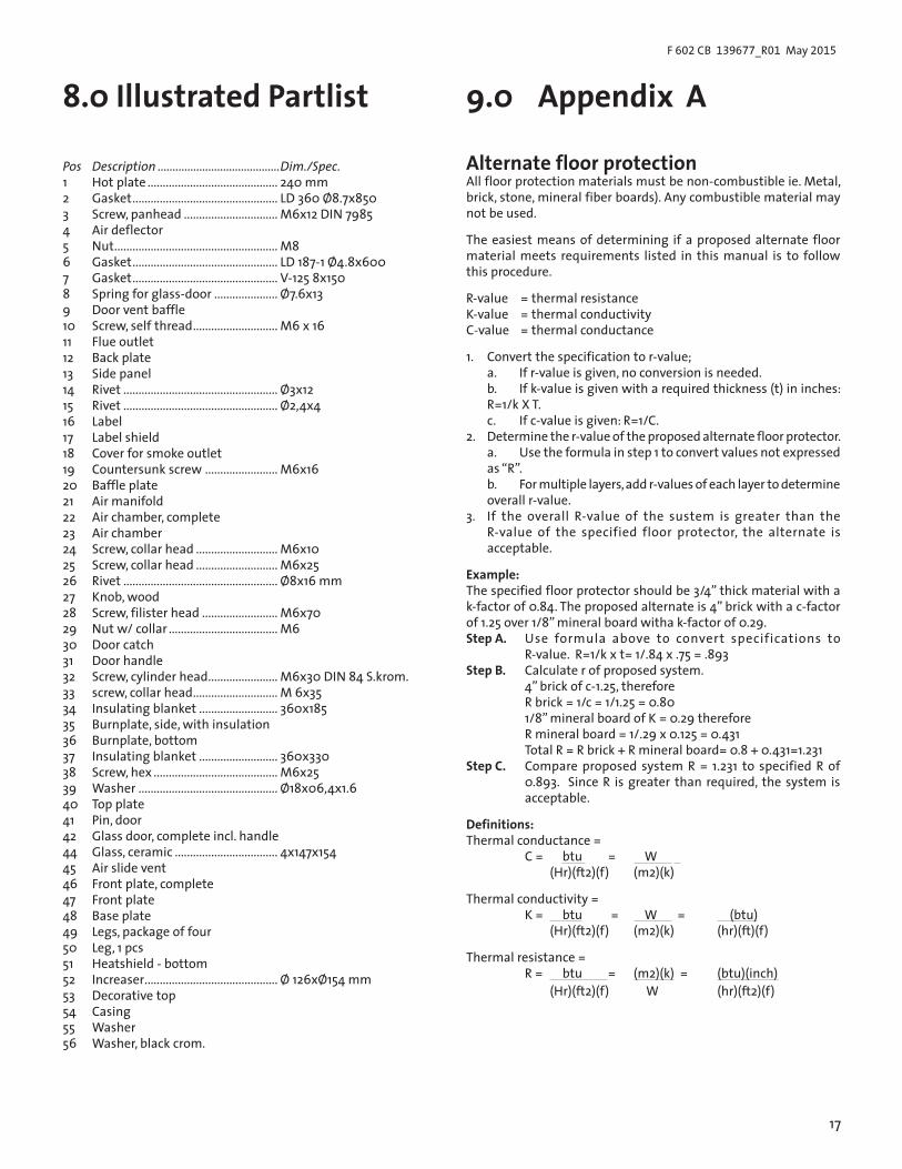
8.0 Illustrated Partlist
Pos Description .........................................Dim./Spec.1 Hot plate ........................................... 240 mm2 Gasket ................................................ LD 360 Ø8.7x8503 Screw, panhead ............................... M6x12 DIN 79854 Air deflector5 Nut ...................................................... M86 Gasket ................................................ LD 187-1 Ø4.8x6007 Gasket ................................................ V-125 8x1508 Spring for glass-door ..................... Ø7.6x139 Door vent baffle10 Screw, self thread ............................ M6 x 1611 Flue outlet12 Back plate13 Side panel14 Rivet ................................................... Ø3x1215 Rivet ................................................... Ø2,4x416 Label17 Label shield18 Cover for smoke outlet19 Countersunk screw ........................ M6x1620 Baffle plate21 Air manifold22 Air chamber, complete23 Air chamber24 Screw, collar head ........................... M6x1025 Screw, collar head ........................... M6x2526 Rivet ................................................... Ø8x16 mm27 Knob, wood28 Screw, filister head ......................... M6x7029 Nut w/ collar .................................... M630 Door catch31 Door handle32 Screw, cylinder head ....................... M6x30 DIN 84 S.krom.33 screw, collar head ............................ M 6x3534 Insulating blanket .......................... 360x18535 Burnplate, side, with insulation36 Burnplate, bottom37 Insulating blanket .......................... 360x33038 Screw, hex ......................................... M6x2539 Washer .............................................. Ø18x06,4x1.640 Top plate41 Pin, door42 Glass door, complete incl. handle44 Glass, ceramic .................................. 4x147x15445 Air slide vent46 Front plate, complete47 Front plate48 Base plate49 Legs, package of four50 Leg, 1 pcs51 Heatshield - bottom52 Increaser ............................................ Ø 126xØ154 mm53 Decorative top54 Casing55 Washer56 Washer, black crom.
9.0 Appendix A
Alternate floor protectionAll floor protection materials must be non-combustible ie. Metal, brick, stone, mineral fiber boards). Any combustible material may not be used.
The easiest means of determining if a proposed alternate floor material meets requirements listed in this manual is to follow this procedure.
R-value = thermal resistanceK-value = thermal conductivityC-value = thermal conductance
1. Convert the specification to r-value; a. If r-value is given, no conversion is needed. b. If k-value is given with a required thickness (t) in inches:
R=1/k X T. c. If c-value is given: R=1/C.2. Determine the r-value of the proposed alternate floor protector. a. Use the formula in step 1 to convert values not expressed
as “R”. b. For multiple layers, add r-values of each layer to determine
overall r-value.3. If the overall R-value of the sustem is greater than the
R-value of the specified floor protector, the alternate is acceptable.
Example:The specified floor protector should be 3/4” thick material with a k-factor of 0.84. The proposed alternate is 4” brick with a c-factor of 1.25 over 1/8” mineral board witha k-factor of 0.29. Step A. Use formula above to convert specifications to
R-value. R=1/k x t= 1/.84 x .75 = .893Step B. Calculate r of proposed system. 4” brick of c-1.25, therefore R brick = 1/c = 1/1.25 = 0.80 1/8” mineral board of K = 0.29 therefore R mineral board = 1/.29 x 0.125 = 0.431 Total R = R brick + R mineral board= 0.8 + 0.431=1.231Step C. Compare proposed system R = 1.231 to specified R of
0.893. Since R is greater than required, the system is acceptable.
Definitions:Thermal conductance = C = btu = W (Hr)(ft2)(f) (m2)(k)
Thermal conductivity = K = btu = W = (btu) (Hr)(ft2)(f) (m2)(k) (hr)(ft)(f)
Thermal resistance = R = btu = (m2)(k) = (btu)(inch) (Hr)(ft2)(f) W (hr)(ft2)(f)

18
F 602 CB 139677_R01 May 2015
A. LIMITED LIFETIME WARRANTY, parts only: Jøtul North America Inc. (JØTUL) warrants, to the original retail purchaser, that those baffle and air manifold components of the Jøtul or Scan Stove or Fireplace Insert specified above will be free of defects in material and workmanship for the life of the product. This warranty is subject to the terms, exclusions and limitations set forth below. B. LIMITED FIVE YEAR WARRANTY - Cast Iron and Steel Components: JØTUL warrants, to the original retail purchaser, that those components of the Jøtul or Scan Stove or Fireplace Insert specified above will be free of defects in material and workmanship for a period of five (5) years from the date of purchase. This warranty is subject to the terms, exclusions and limitations set forth below. C. LIMITED TWO YEAR WARRANTY - Enamel Finish: JØTUL warrants, to the original retail purchaser, the enamel finish on cast iron components of the Jøtul Stove or Fireplace Insert specified above against peeling or fading for a period of two (2) years from the date of purchase. This warranty is subject to the terms, exclusions and limitations set forth below. D. LIMITED ONE YEAR WARRANTY - Electrical Components (blowers, thermostatic switches): JØTUL warrants, to the original retail purchaser, that those components of the Jøtul or Scan Stove or Fireplace Insert specified above will be free of defects in material and workmanship for a period of one (1) year from the date of purchase. This warranty is subject to the terms, exclusions, and limitations set forth below:
JØTUL will repair or replace, at its option, any of the above components determined by JØTUL to be covered by this warranty. You must, at your own expense, arrange to deliver or ship the component to an authorized Jøtul or Scan dealer and arrange for pickup or delivery of the component after repairs have been made. If, upon inspection, JØTUL determines that the component is covered by this warranty, the repair or replacement will be made as set forth above.
This warranty is not transferable and is extended only to, and is solely for the benefit of, the original retail purchaser of the Jøtul or Scan Stove or Fireplace Insert. This paragraph sets forth the sole remedy available under this warranty in the event of any defect in the Jøtul Scan Stove or Fireplace Insert.
The warranty period for any replaced component will be the remaining unexpired portion of the warranty period for the original component.
Please retain your dated sales receipt in your records as proof of purchase.
EXCLUSIONS AND LIMITATIONSNOTICE: This warranty is void if installation or service is performed by someone other than an authorized installer or service agency, or if installation is not in conformance with the installation and operating instructions contained in this owner’s manual or local and/or national fire and building regulations. A listing of local authorized installers, service agencies and gas suppliers can be obtained from the National Fireplace Institute at http://www.nficertified.org/.
This warranty does not cover the following:1. Repair or replacement of parts that are subject to normal
wear and tear during the warranty period or to parts that may require replacement in connection with normal maintenance. These parts include paint, gaskets, burn plates, ceramic insulation blankets, skamol baffles and panels, firebricks, fire grates, or glass (Ceramic glass is warranted against thermal breakage only).
2. Damage due to incorrect installations not in conformance with the installation instructions contained in this owner’s manual or local and/or national fire and building regulations.
3. Damage, including damage to enamel surfaces, caused by improper operation, over-firing, and/or misuse. Improper operation, such as burning the stove with the ash door open, can damage the stove. Over-firing occurs when any part of the stove glows red. Over-firing can also be identified by warped plates, rust-colored cast iron, paint pigment that has turned dusty white, or bubbling, cracking and discoloration of the enamel finish. Misuse includes, without limitation, use that is not in conformance with the operating instructions contained in this owner’s manual.
4. Damage to enamel finish including chipping, mechanical or chemical abrasion, crazing, staining, or rust caused by high humidity or salt air environments.
5. Damage from or repair of rust. Use of a stove-top steamer can cause rust.
6. Damage due to service performed by an installer or service agency, unless otherwise agreed to in writing by JØTUL.
7. Damage caused by unauthorized modification, use or repair.
10.0 Jøtul Woodburning Product Limited Lifetime WarrantyEffective January 1, 2013
19
F 602 CB 139677_R01 May 2015
IN NO EVENT SHALL JØTUL, ITS PARENT COMPANY, SHAREHOLDERS, AFFILIATES, OFFICERS, EMPLOYEES, AGENTS OR REPRESENTATIVES BE LIABLE OR RESPONSIBLE TO YOU FOR ANY SPECIAL, INDIRECT, INCIDENTAL, CONSEQUENTIAL, PUNITIVE OR OTHER SIMILAR DAMAGES, INCLUDING, BUT NOT LIMITED TO, LOST PROFITS, LOST SALES, INJURY TO PERSON OR PROPERTY, OR DAMAGES TO A STRUCTURE OR ITS CONTENTS, ARISING UNDER ANY THEORY OF LAW WHATSOEVER. ALL IMPLIED WARRANTIES, INCLUDING THE IMPLIED WARRANTIES OF MERCHANTABILITY AND FITNESS FOR A PARTICULAR PURPOSE, OR OTHERWISE, ARE LIMITED IN DURATION TO THE LENGTH OF THIS WRITTEN WARRANTY. EXCEPT AS EXPRESSLY SET FORTH HEREIN, JØTUL MAKES NO ORAL, WRITTEN OR OTHER WARRANTY WITH RESPECT TO JØTUL OR SCAN STOVES OR FIREPLACES.
Some states do not allow the exclusion or limitation of incidental or consequential damages, or limitations on the length of implied warranties. Therefore, the above exclusions or limitations may not apply to you. This warranty gives you specific legal rights, and you may have other rights, which vary from state to state.
JØTUL reserves the right to discontinue, modify or change the materials used to produce the Jøtul or Scan Stove or Fireplace Insert. JØTUL shall have the right to replace any defective component with substitute components determined by JØTUL to be of substantially equal quality and price.
The dollar value of JØTUL’s liability for breach of this warranty shall be limited exclusively to the cost of furnishing a replacement component. JØTUL may at its discretion discharge all obligations by refunding the wholesale price of any defective part or appliance. JØTUL shall in no event be liable for any special, indirect or consequential damage of any nature which is in excess of the original wholesale purchase price of the product. JØTUL shall not in any event be liable for the cost of labor expended by others in connection with any defective component. Any costs or expenses beyond those expressly assumed by JØTUL under the terms of this warranty shall be the sole responsibility of the owner(s) of the Jøtul Stove or Fireplace.
No dealer, distributor, or other person is authorized to modify, augment, or extend this limited warranty on behalf of JØTUL. NO MODIFICATION OR CHANGE TO THIS WARRANTY WILL BE EFFECTIVE UNLESS IT IS MADE IN A WRITTEN DOCUMENT MANUALLY SIGNED BY AN AUTHORIZED OFFICER OF JØTUL.
An authorized installer may have been provided with certain information related particularly to the Jøtul or Scan Stove or Fireplace; however, no authorized installer or other person who may service the appliance is an agent of JØTUL. No inference should be made that JØTUL has tested, certified, or otherwise pronounced any person as qualified to install or service the appliance. JØTUL shall not be liable or otherwise responsible for any error or omission by a person installing or servicing a Jøtul or Scan Stove or Fireplace Insert.
If you believe your Jøtul or Scan Stove or Fireplace Insert is defective, you should contact your nearest authorized Jøtul dealer, who will process a warranty claim. IN ORDER TO QUALIFY FOR WARRANTY COVERAGE, JØTUL MUST RECEIVE NOTICE OF A POSSIBLE DEFECT WITHIN SIXTY (60) DAYS OF THE DATE THE DEFECT IS FIRST DISCOVERED, OR REASONABLY COULD HAVE BEEN DISCOVERED.
This warranty is given by Jøtul North America, Inc., 55 Hutcherson Drive, Gorham, Maine 04038 USA
8. Costs incurred by travel time and/or loss of service.9. Labor or other costs associated with the repair of
components beyond the warranty period.10. Damage incurred while the Jøtul or Scan Stove or
Fireplace is in transit.

20
F 602 CB 139677_R01 May 2015
Jøtul maintains a policy of continuous product development. Products supplied may therefore differ in specification, colour and type of accessories from those illustrated and described in this manual.
QualityJøtul North America employs a quality system that conforms to NS-EN ISO 9001 for product development, manufacturing, and distribution of stoves and fireplaces. This policy gives our customers quality and safety piece of mind as a result of Jøtul’s vast experience dating back to when the company first started in 1853.
We appreciate your trust in welcoming our product into your home and invite your comment and appraisal of our efforts to provide you with the finest in home hearth products.
Jøtul North America Inc.55 Hutcherson DriveGorham, Maine 04038USA
Jøtul AS, P.o. box 1411N-1 Fredrikstad, Norway
139677_R01 M
ay 2015