joshua greer (1) instructor: mike braddock spring ’09 july ... · project completed according to...
TRANSCRIPT

EML2322LDesign and Manufacturing Laboratory
Design Report 1
Team 1C
Joshua Greer (1)Eric L Pheterson (2)Matthew York (3)
Instructor: Mike Braddock
Spring ’09
July 9, 2010

Introduction / Problem Statement
For this semester of design and manufacturing laboratory we were given a very unique problem statement. We were asked to design robot capable of retrieving four tennis balls placed inside a 10 x 20 ft enclosed arena and place them in a plastic bucket as quickly as possible. A non-transparent entry portal 3 feet wide x 3 feet tall x 6 feet long must be passed through while entering and leaving the arena. The arena will be marked off by wooden 2 x 4’s placed on edge. The tennis balls will be placed on 1” PVC pipe stands inside the arena, which are free to slide and/or tip over. Two of the tennis balls will be positioned 4 inches off of the floor and the other two will be positioned 12 inches off of the floor (all measurements relative to the center of the balls). All of the balls must be collected before any are placed in the bucket and the balls may not touch the ground at anytime.
Design Specifications & Requirements
The robot shall fit through a 3ft x 3ft portal to enter the arena and must fit in a 26 inch cube prior to the start of a run and must begin the run five feet from the portal. During construction, all parts must fit in a 17” x 12” x 15” container. The robot must fit a 12” x 8” x 6” controller box, which must be attached in less than five minutes. Due to the electronics, liquids may not be used in the robot. The robot must be self-propelled and all balls must be collected before any are placed in the bucket. During a trial, the floor paint cannot be scratched or damaged. Each trial must be completed in five minutes and during the trial the bucket cannot leave the arena. While there is no monetary cap on the design, only $50 is provided by the University of Florida. Twelve linear feet of 80/20 are available for use. The robot must utilize no more than four motors and wheels.
Robots will be graded on their design, student initiative, and performance.

Performance
Sixty second penalties will be awarded for knocking over or removing a the bucket from the arena as well as failing to place all four balls in the upright bucket or letting a ball hit the ground.
Student Initiative / Design
Students must express interest in the design and manufacturing of the robot while using the process, technology, and knowledge they have garnered from the class and lab. It is also optimal for students to complete their robot with enough time to test and modify as needed to enhance aesthetics and insure completion of the set task. Students are also required to communicate well while working efficiently with and respecting the lab and other students and teachers.
Students will be graded on several points with a scale of 1-5, 5 being excellent and 1 being poor. i. Project completed according to instructions listed for the assignment
(10%)ii. Attention to detail and development of technical ability (20%)iii. Overall Effectiveness/success of project (20%iv. Quality of project (10%)v. Design Reports (40%)vi. Respect for laboratory resources and staff; project disassembly and
cleanup (-10%)

Background Information (Joshua Greer (1))
CHASSIS DEVELOPMENT
Design
When designing ones mobile platform, one has to consider the space needed for all parts as well as the accessibility of the pieces. The simplest designs really come down to a three wheeled chassis vs. a 4 wheeled chassis.
Three vs. Four Wheeled
Three wheeled chassis are fundamentally lighter because of their fewer wheels and simplified chassis; this means that it takes less power to get them moving. Weight reduction can also mean that one can get the same velocity with a smaller engine. Three wheel systems generally have a shorter turn radius then four-wheeled systems. However, unless engineered correctly, three-wheeled systems begin to show balance issues. (Further research under Wheels)
Beating the Balance Issue
In order to negate balance issues it is optimal to create weight symmetry across the vertical axis of the chassis. In a three wheeled system, it is necessary to place the bulk of your weight on the axis of the drive wheel’s centerlines; this will prevent over rotation in extreme circumstances as well as giving more friction to the drive wheels.
MATERIALS
AluminumStrength Aluminum has a large strength to weight ratio. However, the same structure built in aluminum instead of steel has a much greater chance of deformation.
Plate Stiffness As a comparison we will juxtapose aluminum with steel. Steel has a much greater stiffness and has a higher yield per square inch. It was shown to be by Michael Kaston, a certified boat structural engineer, that a thickness of an inch an a half in aluminum has about a 51k yield psi of surface area, which is about 29% greater then that of steel with an equivalent section of plate. According to these two material’s structural efficiency (stiffness to density), anything designed with an equal stiffness will weigh around 57% less in aluminum then steel.

Welded Strength Continuing with our comparison between aluminum and steel, we see that strength of welded aluminum is less then that of steel. However, if you keep with equivalent stiffness, the difference is negligible assuming your calculations were originally correct.
Extra Facts Aluminum is much easier to work with because it is abrasive, meaning we can use many tools to cut and shape our material.
Plastic (specifically HDPE)Strength HPDE has very little rigid strength and will bend and flex if not held to proper thickness. In order to produce a lightweight, strong base for your robot, it is better to reinforce the HDPE with aluminum. HDPE does not bend and will incur significant structural damage if forced to. However, by reinforcing HDPE with aluminum we garner the high yield while keeping our robot lightweight.
Weight The weight difference between aluminum and HDPE is significant enough for us to consider using this material as the base of the robot. However, while the weight is low, the pieces are not very strong and fracture if forced to sustain large amounts of weight.
Machinability HDPE is very easy to cut and shape, even by hand. This allows for designs to be made around tight specifications and, cuts down on weight sacrifices in other sections of the chassis.
Working with HDPE When working with HDPE you should never tap it, as this will fail after only a few uses. HDPE should not be used to hold heavy weights up. A combination of a rigid steel bracket mounted with steel bolts to HDPE is the best mount for a wheel with an HDPE base
Velcro Not much to say though it should be considered for easy change of batteries and possibly computer as it gives easy accessibility.
Steel Steel is an alloy consisting of mostly iron and varying degrees of carbon. The carbon acts as a hardening agent and creates very stiff, rigid material. Steel is ideally used when one must mount a weight and cannot have warping or flexing of the mount. It is very cost friendly and easily machined, if not light weight. Steel can be treated in several different ways to increase its strength dramatically.

When working with steel, one designs to the operational yield point and never past it. If one exceeds the yield point the steel plate permanently deforms as it is rigid and not flexible. Therefore our limiting factor is always operational yield point.
80-20 80/20 is a light weight aluminum that must be considered as it is supplied free to us in what they refer to as the T-slots. 80/20 is an extremely lightweight durable aluminum that works similarly to an adult erector set. There are over 300 attachments including elbow joints and linear slides all being industrial strength.
Material Specifications For 80/20 T-Slotted Aluminum ProfilesMaterial Specifications For 80/20 T-Slotted Aluminum ProfilesMaterial Specifications For 80/20 T-Slotted Aluminum Profiles
• Yield strength 241.1 N/mm2 (35,000 psi) minimum• Tensile strength 262.0 N/mm2 (38,000 psi) minimum• Elongation A5 minimum 10%• Elongation A10 minimum 8%• Elasticity E approximately 70,326.5 N/mm2 (10,200 k lbs./sq. in.)• Brinell hardness approx. 75 HB (Rockwell hardness approximately E-88)• Profile conforming to DIN 17 615 specifications• Twist per 304 mm (1 foot) of length not to exceed .25 degree and total twist over 6.1 m (20
feet) of length not to exceed 1.5 degrees• Flatness 0.32 mm (.004 in.) per 25.4 mm (1 in.) of width• Straightness 0.32 mm (0.0125 in.) per 304 mm (1 foot) of length, not to exceed 3 mm (.118
in.) over 6.1 m (20 feet) of length• Unless otherwise specified, all extrusions will have etch and clear (204R1) anodizing with
depth of 0.010 mm (.0004 in.) and surface hardness of approximately 250 HV (anodized extrusions should not be welded because of toxic fumes)
The 2 degree drop-lock This is a 2 degree decline on the T-slot flang. When a fastener is locked to the necessary, or beyond the necessary, torque the flang will flex to the adjoining profile creating pressure that prevents vibration and motion.
Linear Slide Information
o Give any application a smooth range of motion
o Self lubricating UHMW-PE bearing pad
o Standard and High Cycle bearings available
o UniBearings™ are 80/20's customizable linear bearings
15-Series High-Cycle Bearing
These bearings contain inserts that allow for heavy loads and frequent use. The pads also allow for heavy acceleration, deceleration, and sudden stops. This type of bearing is specifically designed for high cycle usage and works especially well with an actuator.
Uni-Bearings The Uni-Bearing allows all and any T-slot 80/2 to slide linearly without taking a frame apart. The Uni-Bearing allows you to either slide the bearing or the T-slot attached to the bearing
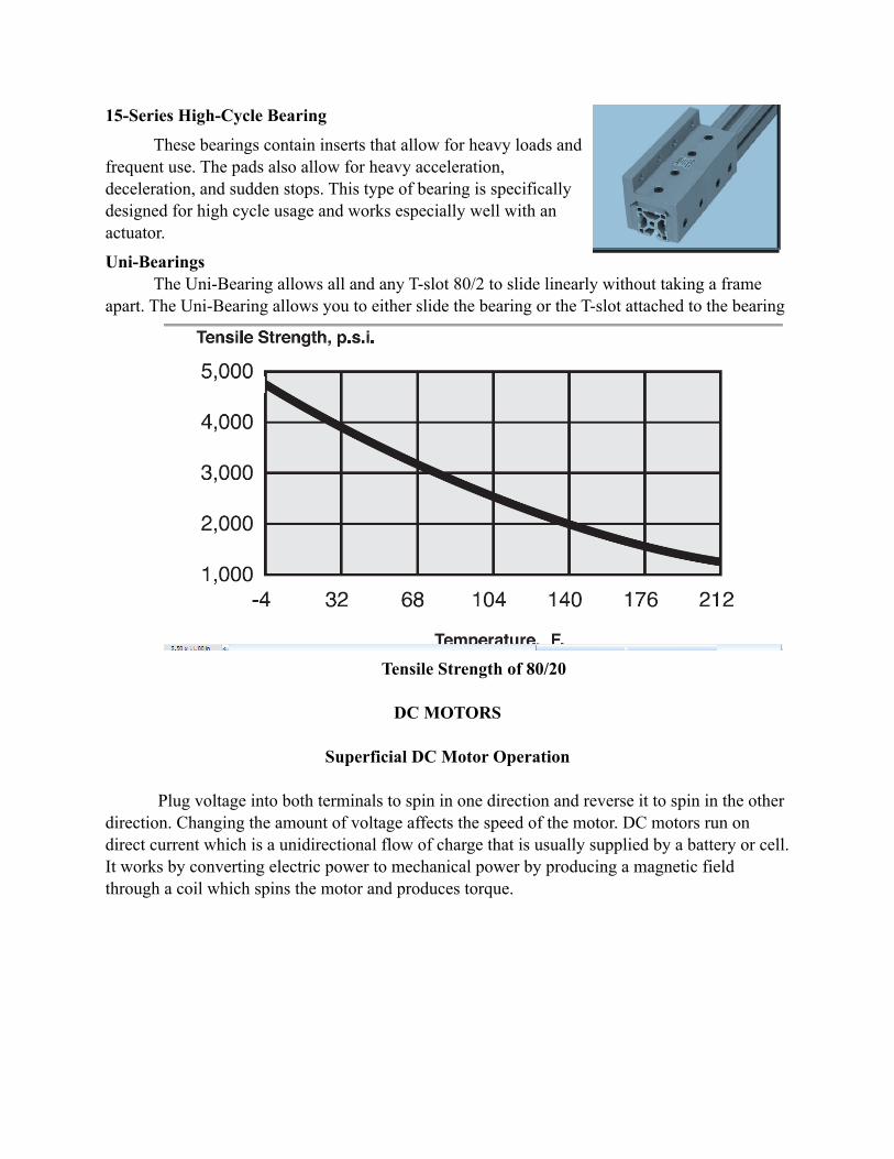
Tensile Strength of 80/20
DC MOTORS
Superficial DC Motor Operation
Plug voltage into both terminals to spin in one direction and reverse it to spin in the other direction. Changing the amount of voltage affects the speed of the motor. DC motors run on direct current which is a unidirectional flow of charge that is usually supplied by a battery or cell. It works by converting electric power to mechanical power by producing a magnetic field through a coil which spins the motor and produces torque.

Voltage
DC motors are non-polarized and thus reversing the voltage will have no negative affect. Voltage is directly related and proportional to torque. DC Motors are rated at the voltage they run the most efficiently at.
In Depth DC Motor
DC motors turn electricity into motion through electromagnetic induction; basically the movement of a magnetic field to induce a current. The faster the movement the higher the voltage, as can be seen in Faradays bar magnet experiment. The interplay of the magnetic fields of the electro-magnet and the stationary-magnet create the torque as represented by the green arrows in this picture.
Torque
The torque of an electric motor is dependent on the flux and armature. As flux increases, speed decreases while torque increases. If more coils are added to the armature more torque is generated. Greater Torque means greater acceleration. Society of Robots suggests, “If you have 2 motors on your robot, make sure the stall torque on each is enough to lift the weight of your entire robot times your wheel radius.” There are two torque values we must pay attention two, operating torque, which is what the motor was designed to give, and stall torque, the torque required to stop the motor from rotating.
Torque vs. Rotational Velocity
Torque_Old * Velocity_Old = Torque_New * Velocity_New
Using data sheets it’s easy to see how you would adjust the torque or velocity of your motor using gearing. If you wanted to achieve a 3/1 gearing ratio, meaning you wanted 3 times the torque or velocity, you would use a 3 times larger diameter on your gear. This will become important for our design of the bucket lifting.

Remote Control
The remote we will be using functions by allowing more of or reversing voltage to the motor there by causing rotation at greater speed and acceleration.
GEARS
Gearing
Gearing is the act of reducing or increasing the torque of a motor by transferring motion from a smaller gear to a larger. A great example of this is an electric screw driver, it needs a large amount of torque to unscrew a screw but the motor inside runs at a high speed with little torque. By gearing this motor we provide a larger torque with less speed. Gears are also good for adjusting the angle of motion. Ratio is defined as the distance from the center of the gear to the point of contact. Modern Gears use an involute to create a constant ratio which in-turn creates a constant turning speed ratio between two gears. Pitch diameter is the average contact distance.
Types
Spur Gears: Simple gearing with the highest possible efficiency because of its simplicity. These tend to be loud as there is constant impact between gears. Helical Gears: Can be operated at an angle but run smoother then spur gears and reduce teeth breakage. However, efficiency is about 80%. These gears work by creating a thrust load when they mesh. These tend to run quietly.Bevel Gears: These are basically used for changing rotation angle and suffer large reductions in efficiency at around 70% Rack and Pinion: This gearing is used for changing rotational movement to translational movement with 90% efficiency. Worm Gear: These gears have very high gearing ration as the amount of teeth contacted is maximized. They do however suffer from vary low efficiency at 70%. The most unfortunate part of this gearing method is that the worm can turn a circular gear but not the other

way around. It will not however rotate do to gravity. This makes it ideal for lifting things. It is common for worm gears to have a reduction of 20:1 ratio.
WHEELS
General Wheel Operation
Wheels support the chassis and allow the robot to roll. Powered wheels provide a force which can propel the robot. An effective wheel is strong enough to maintain its shape under the weight of the robot, but light enough to where it meets your energy requirements to turn it. Larger wheels give larger gear ratios. We also would like minimal rolling resistance.
Attaching the Wheel
Bore A bore is a center hole that is slightly smaller then the diameter of the axle in which they are intended to fit. Using a bore is known as a push fit. Idler Mounting The simplest mounting is the idler mounting. This is used for non powered wheels and allows for 360 degree rotation.
Jamming This method requires you to drill a hole slightly smaller then the diameter of the motor shaft, fill it with adhesive and force it in the axle of the wheel. The Adhesive should create enough friction to propel the wheel given a force. This is not ideal due to wear on the adhesive.
Key hole This method allows you connect directly into the motor by purchasing a kit that locks a shaft with a key into the motor

Bolt Mounting Using multiple bolts to attach the wheel to a spindle on the motor. It requires you to drill holes through the wheel if none already exist. A large washer should be used to distribute the force. This is one of the most sturdy methods of mounting and does not produce much wear from multiple uses.
Wheel Texture
Smooth texture can result in skidding on smooth surfaces. However this appears ideal for the idler wheels as you really want it to have no affect on movement but only on balance. Rough texture allows for optimal breaking and stopping, but creates large inefficiencies relating to the frictional force vs. the powered force.
Width
A large width also increases the frictional resistance of the wheel and can reduce and hinder your ability to turn depending on your system style. Width can cause inefficiencies in many areas. Needless to say a large diameter with small width produces the greatest speed.
Wheel Diameter
On every motor is an operational torque and velocity. The Larger the diameter of the wheel the greater the speed but smaller the torque. The size of your wheel is dependent on the strength of your motor and the amount of torque you need. Using the same motor, if a large diameter wheel is chosen, will move an object much faster than a smaller wheel, while if a small wheel is chosen, it will move much more weight than a large wheel because it offers more torque.
Wheel Arrangement
Common wheel arrangements consist of three or four wheels, where specialty-purposes call for more. The four-wheel arrangement is set up exactly like a car with two in the front and two in the back. This arrangement offers unbeatable stability over the 3-wheel design, although the stability is not always necessary. A four-wheel design also adds a complication of steering and may require a differential, depending on the application. Steering differential is important because, during a turn, the left and right wheels do not move the same distance. If the two wheels are attached to the same axle, the axle or tires take an unnecessary load during turns. The complication of steering stems from the fact that two wheels need to be turned at the same angle. While this can be done with a gear and pinion system, it is often unnecessary for small robotics application. A three-wheel alternative removes the complication of steering by utilizing the two

necessary powered wheels to do the actual turning on the robot. This can be achieved by spinning these two wheels in different directions. To overcome resistance, the third wheel must be an un-powered, freely spinning wheel, such as a caster wheel. This arrangement is in danger of balance issues, though, as if weight is put on either size of the caster wheel, the robot can fall onto its corner. This must be considered in design so the heavy weight loads are atop the powered wheels and the danger is reduced.
Caster Wheel
The caster wheel is a very easily used piece for your robot. It provides balance with minimal impedance to direction and velocity. The ultimate goal of the caster wheel is to provide stability without friction. This means that less surface area and smaller sizes are the most optimal. A trailing caster follows the drive wheels better then a leading one is pushed. Thus, if the caster is hit by some debris, it is less likely to change your direction from the back of your robot then the front. The drawback to trailing casters is the propensity to flip over when breaking if too much of the weight is in front of the drive wheels. Optimally you want your weight between wheels. Although, it should be noted that a dynamically balanced robot is more stable then a statically balanced one (for instance using no casters). A low coefficient of friction with minimal weight acting normal to the caster is the way to go.
STEERING METHODS
Drive and Steer
The drive and steer method consist of a single drive motor as a separate steering system. The most optimal form of this for a robot would be to apply the drive to a pivoting wheel. That is to say, that while rotating the steering system could pivot the wheel for direction. This option works optimally in both a 4 and 3 wheel system, but is less maneuverable then differential steering. By placing the vertical wheels closer together, you can increase maneuverability while maintaining the increased traction and accuracy provided by Ackerman style steering.
Differential Steering
Differential steering is simple in that by slowing or reversing one motor you change direction by pivoting around the stopped or reversed wheel. This method is extremely simple and affective for indoor robots. However, one of the biggest draw backs to differential steering is that if one motor is not in sync with the other the robot will veer off course.

BALL MANIPULATORS AND TENNIS BALLS
Manipulator
The two most important issues for the ball manipulator are speed and statics. It is important to design a speedy device that both can handle the operation needed performing, as well as doing it in a timely manner. Based on past methods, it seems the speediest and most effective method was a rotating arm which rammed the ball base forcing the ball into a collecting bucket. Because tennis balls weigh very little, as long as a somewhat compact design is generated, none of the motors provided will fail to lift a rotating armor. It seems however, in order to produce the cleanest model, a linear actuator should be used to create the most compact and space friendly robot.
Tennis Ball A tennis ball is a ball designed for the sport of tennis, approximately 6.7 cm (2.7 in.) in diameter and is normally yellow in color and covered in felt. Felt has a coefficient of .22 against steel when dry.
LINKAGES Mechanical Linkages are usually designed to take an input force and generate a different output, like pliers. Linkages commonly have 1 degree of motion and freedom which can be shown by a simple statics equation.
o m = mobility = degrees of freedomo n = number of links (including a single ground link)o j = number of one-degree-of-freedom kinematic pairs (pin or slider joints)
Linkages can be affective at altering motion, velocity, acceleration, force, and torque. The main concern when generating linkages is failure, and factor of safety.

BEARINGS
Many machines we use everyday work because of bearings. A bearing is a device that allows constrained relative motion between two parts. Basically, objects roll better than they slide, and that is what bearings do. When objects slide, friction occurs. This slows the object down. But, when two surfaces roll over each other, friction is drastically less, thus allowed motion that would not occur without the bearing. Bearings reduce friction on many levels. A bearing reduces friction by its shape, material, fluid, and fields. A way that a bearing reduces friction by its shape is through using spheres or rollers. An example of how bearings reduce friction by its material is using plastic which has low surface friction. Bearings use fluid as a lubricant or as a pressurized medium to keep the two solid parts from touching to reduce friction. Lastly an example of how bearings use fields to decrease friction is using magnetic fields to keep the solid parts from touching. Most bearings combine these friction reducing mechanisms. An example of a simple bearing is on the right. This type of bearing is common in common objects such as skate boards.
Types of Bearings
Different bearings have different operating speed limit. Plain bearings usually are the slowest, followed by rolling element bearings, third are fluid bearings and the fastest bearing is magnetic bearings which are only limited by centripetal force overcoming the material strength. Also fluid and magnetic bearings usually have an indefinite life. Two main types of bearings, rolling and plain are both categories of linear bearings. A linear bearing is a bearing designed to provide free motion in one dimension. A rolling bearing is a bearing that carries a load by placing round elements between the two pieces. A rolling bearing uses a shaft in a much larger hole, and cylinders called “rollers.” The rollers tightly fill the space between the shaft and hole. Then as the shaft turns, each roller acts falls into place and keeps rotating. Rolling bearings are very useful while being relatively inexpensive, and light in weight. But, they can carry heavy amounts, are very durable and have very little friction.

Within the category of rolling bearings, there are many different types. There are ball, roller, needle, tapered, and spherical roller bearings. The most common of the types is the ball roller bearing. Ball bearings use spheres instead of cylinders. Roller bearings use cylinders that have greater length than diameter. Needle bearings use long and thin cylinders. Tapered roller bearings use conical rollers that run on conical races. Roller bearings use rollers that are thin at the ends and thick in the middle. A picture of a ball rolling bearing is to the right. Some of the problems of rolling bearings are that small problems can greatly affect them such as small vibrations that can gradually press out the lubricant between the races and rollers. Second, the inner and outer races are complex shapes which make them difficult to manufacture. Lastly there are limits to their lifetime and load capacity. This is because of abrasion, fatigue and pressure induced welding. The second category of linear bearings is plain bearings. Plain bearings are relatively simple and are usually made of only two parts. Because they are so simple they are fairly inexpensive, compact, light weight, and easy to repair. A common plain bearing design utilizes a hardened and polished steel shaft and a soft bronze bushing. Plain self lubricating bearings utilize porous journals within which a lubricant is held. There are two main problems with plain bearings. First, compared to other types of bearings they have high friction. Second, the life time drastically decreases with high speeds.

Conceptual Design Generation (Joshua Greer (1))
The Picaso-P1A was designed to be a creative yet affective way of completing the ball collecting task in the quickest manner. By utilizing linear-slides to raise the bucket and differential steering as well as a sleek compact design, the Picaso-P1A seems poised to break standing records.
ChassisThe chassis was designed to allow optimal room for the scoop mount and motor boxes while maintaining symmetry across the center-line that the three wheels create. The back half of the chassis (1G) is connected to the front half (1F) using three 80/20 pieces and several rigid steel bolts. 80/20 is optimal for this as it will greatly reduce the amount of vibration with its 2 degree drop-off. With an idle wheel of 7” from ground to bracket and powered wheels with 7” diameters, the chassis rest at a natural angle that ensures the balls stay in the scooper. By having the Chassis in two parts with easily assembled 80/20 pieces connecting it, the Picaso-P1A is able to fit neatly inside the allowed storage bin.
Scooper MountThe scooper mount (1A) is the brains of the entire linear slide. Supported by at 13.5” rigid steel frame that is mounted onto the chassis 5.5” from its base, the pinion easily moves from 2” from the ground to 9” in the air. The pinion has been cut with a guide through both vertical sides which support linear slides for stable motion that resist movement in any direction but vertical. The bucket mount is placed 2” from the bottom of the pinion and the pinion teeth are pointed towards the inside of the chassis.
Motor MountThe motor mount (1C) is designed specifically for two reasons. The first reason is to mount the gear and motor at 8.5” from the top of the chassis in order to allow the pinion to correctly slide from one height to the other. The mount also transfers the gravitational force created by the weight of the steel frame, pinion, and scooper.
Gear MountThe gear mount (1B) is created to provide the rest of the height necessary on the pinion, as well as to reduce the impact on the gear by the pinion. The gear is comparatively larger and wider to that of the motors to produce good torque with descent speed, and large strength.
ScooperThe scooper (1D) is designed to collect balls by running into the base of a ball holder causing the ball to fall into the scooper. Once the ball is inside the scooper it angles down toward the left hand corner at 10 degrees. This causes the balls to rest near this back corner. Once the scooper is raised above 9” the balls fall out this corner because of the natural angle of the chassis through the empty hole in the back that was previously blocked by the rigid steel frame.

The Ball RampThe ball ramp (1E) is designed for side unloading of the balls into the bucket. Once the balls fall out of the scooper they run down the ramp and fall into the bucket through a 5” opening at the bottom of the ramp.

Background Information (Eric L Pheterson (2))
Wheels
Picking the right wheel for a robot to complete its task is synonymous with picking the right shoe for playing a sport. The attributes we’ll be analyzing are wheel material, diameter, width, as well as wheel alternatives such as tank treads.
Diameter
The wheel diameter depends largely on the motor to which it is attached. A large wheel produces great speed while a small wheel produces greater torque. If our engine was to be very weak, or provide little torque, a small wheel diameter is desired because less effort is being put into turning a large wheel and more is going directly into moving the robot. Small wheels do have a limit, though. It is important to pick a wheel diameter larger than the diameter of the motor itself. If a wheel of the motor diameter is chosen, the motor would be mounted almost touching the ground and would leave the robot with little to no ground clearance. In this particular project, that would not affect functionality much but in general we should pick a larger wheel. In our robot, we’ll be provided with a motor capable of providing ample torque to turn a large wheel and still move the robot at a manageable speed. For this reason, a larger wheel is likely to be chosen simply because the advantage of a smaller wheel is a moot point for our project.
Width
Wheel width is less important than wheel diameter as it affects the overall performance less. Width provides our wheel diameter with surface area, the wider the wheel, the greater the surface area. With surface area comes friction and resistance. Depending on the material to be chosen, a small width may be sufficient to keep traction even at high speeds. For example if a rubber-type material were chosen than a very thin wheel, say a 1/4” wide, would be able to keep traction. In contrast, if the wheel were made out of concrete or plastic, a width of 1/4” would have a difficult time keeping traction with the painted concrete floor even at slower speeds. Later we will discuss wheel material, which will probably be a high-traction rubber-type material. Assuming we have a high-traction wheel, a small width of 1” or so is plenty sufficient to keep the robot rolling.
Material
Wheel material may be the most important decision to be made in selecting wheels. While finding coefficients of friction can be difficult (through research), one is very clear: rubber

on concrete is 0.85 versus 0.62 for wood on concrete1. To throw a wrench into the measurements, we’re actually rolling on painted concrete which will result in a different CoF, but for our purposes this information is sufficient. Rubber is almost unanimously used for rolling robots, with only one alternative, foam. Foam’s advantage is that it weighs much less compared to a rubber-like material yet still provides traction. One catalog offers wheels made of a foam/rubber composite that is both light and high in traction2. Weight was not a requirement for our project, therefore we will most likely not be going for the foam wheel alternative. Rubber provides more than enough traction for our purposes and the weight is insignificant compared to the rest of the robot.
Alternatives
Wheel treads offer something that most wheels can’t by themselves, traction in nearly all terrain. They function by using many powered wheels to roll one large tread, which rolls the robot over a slippery or uneven terrain in which individual wheels would get stuck by themselves3. If terrain is known and manageable, a standard wheel is preferred because it is cheaper and easier to install. Omni-directional wheels6 are also an alternative which allows a robot to move in any direction without ever having to turn. This unique ability is made possible by using round wheels which have perpendicular, high traction, round wheels along its rim. The perpendicular wheels allow a large wheel to either spin about its center axis or be pulled by other wheels along its center axis with little resistance. Imagination is the limit to how a robot can be moved4. A robot can roll atop a single, constantly-moving ball, crawl as a lizard, or sliver as a snake. The question lies in what are the requirements of the robot and how much programming is required.
Arrangement
As discussed in wheel alternatives, there are many ways to contact your robot with its terrain. Besides choosing the actual material, we must consider how much of this material -- specifically, three wheels versus four. Two wheeled robots are possible5, but require on-board balancing analysis which is unnecessary for this project. There are two ways to pull off a three-wheeled robot, one powered wheel complete with a steering mechanism paired with two dead
1 Coefficient of Friction Values for Clean Surfaces, http://www.school-for-champions.com/science/friction_coefficient.htm
2 The Robot Marketplace, http://www.robotcombat.com/marketplace_wheels.html
3 SuperDroid Robots, http://www.superdroidrobots.com/shop/category.asp?catid=55
4 Benjamin Stephanʼs Research, http://research.bstephens.net/lims/tunnelrobot/
5 nBot, http://www.geology.smu.edu/~dpa-www/robo/nbot/

wheels6, or two powered wheels paired with one dead wheel7. For either three-wheeled design it is important to keep the center of gravity towards the center of the triangle created by the three wheels. Turning can be achieved with a two-powered wheel design by moving either of the two wheels independently. Because this is so simple of a design, the wheels can be permanently mounted, decreasing the risk of error or breakage. For a one-powered wheel design, the front center wheel is spun by a chain of some sort and is turned by a separate servo. For both designs, two motors are essential. Alternatively, a four wheel design may be chosen which introduces a steering challenge. Now at least two wheels need to be rotated in order to turn the robot. This can still be done using only two motors but requires a complicated axle mechanism. For our purposes, the easiest platform to execute would be the three wheeled design which hosts two powered wheels. We would have one dead wheel which can spin 360 degrees to keep the robot balanced.
Robot Platforms
All the components of a robot must rest on some central base which can support the load and sustain the movement. This base can be called a frame or a platform and can be constructed in any number of ways.
80/20
A simple construction method utilizes 80/20, an “Industrial Erector Set” made of aluminum with lengths that connects very quickly and easily. The advantage of using 80/20 is that rapid prototyping and construction is possible and the parts themselves can be used in creative ways to form a variety of shapes. The trick to 80/20 is behind their method: 80% of your results comes from 20% of your efforts. The erector set has aluminum rods with grooves cut out. These grooves allow “T-Slots” to slide in to place, any place, and be positioned, at any angle, then be tightened using a standard hex tool.
Standard Shape for 80/20 Length 80/20 is available in many sizes and configurations but maintains the same useful functionality. Many adaptors and parts are designed to fit onto the 80/20 length to increase its
6 Trikebot, http://www-2.cs.cmu.edu/~illah/PAPERS/Paper68Trikebot.pdf
7 Robot Design Basics, http://en.wikibooks.org/wiki/Robotics/Design_Basics/Physical_Design

abilities. One such part allows linear movement8 along a length by grabbing three sides and keeping resistance low. As flexible as 80/20 is, it may not always provide the strength necessary for the job. Sometimes a stronger approach is necessary, such as using raw materials and a welding machine.
Aluminum
An alternative robot platform may be made out of solid aluminum or a similarly strong metal. A possible method is to use a solid sheet of aluminum as the base and mount everything onto and above this sheet. For extra support, an 80/20 frame can be mounted to the sheet. To mount above the sheet, rods and supports can be welded to the base and extra parts can be affixed to these new supports. For low-lying parts, a bolt-type method can be used which utilizes a length of thread and two nuts which secure the thread normal to the base. Once this thread is secure, parts can be secured to the support via another nut on the thread. For parts that require more support, or will be a distance above the base, more rigid supports are required. Welding solid aluminum supports to the base will do the trick. Alternatively, thicker solid supports can be bolted to the base. While welding an entire structure will likely be the most rigid, it is not the most time-effective and doesn’t allow room for the idea to change. In an actual application where both resources are available, using a them in tandem can be the best option. Using a sheet as the base and 80/20 for supports, all design requirements will likely be met.
Steering
As discussed rather shortly, steering is directly related to the robot platform chosen. The simplest steering method is referred to as differential drive control9, which means two wheels are controlled independently to move and turn the robot. Alternatively, we have a ‘Drive and Steer’ style of steering which has one or two powered wheels and one or two turning wheels (depending on a three or four wheel design). For three wheel robots, either method isn’t too difficult to implement, but differential drive control is easier because no controlled rotating wheel is necessary, which would require extra parts above the differential design. For four wheeled robots, steering requires an axle which turns at least two of the four wheels. This is far more complicated than the steering mechanism for a steer and drive three-wheeled system, and so, is too much for this project. For the differential drive control design with three wheels, a caster wheel is necessary which provides little resistance and rotates freely. Due to the nature of this wheel’s purpose, the material of the tire isn’t too important. The consideration on the table for casters is starting
8 Linear Motion Solutions, 80/20, http://www.8020.net/Solution-8.asp
9 Richard Torrens, http://www.4qd.co.uk/robot/start.html#das

distance, the distance it has to be pushed before it starts rolling in that direction. We find that using a larger diameter decreases starting distance10, and so, is preferred. Four four wheeled designs, it’s known that two of the wheels must turn, but which two is the topic on the table. It can either steer like an automobile with the front two wheels turning, or like an airplane flies, with the steering in the back (as in a rudder). The argument boils down to a question of stability11, when using the rear wheels, the steering geometry is reversed resulting in negative caster and negative trail. These differences introduce complexities which are difficult to overcome without great practice.
Vertical Raisers
As part of the design, a ball catcher will need to be raised about 10-12” in the air. This can be done through a few means, the most convenient of which may be a linear slide paired with a ball and pinion system.
Linear Slide
A linear slide is basically a pillow block rested atop a steel shaft which slides easily in a linear direction even while moments attempt to rotate the pillow block in any direction. This can be mounted vertically or horizontally and they come either motorized or simply as a guide. While many companies manufacture linear slides, they design many of them for different purposes and usually manufacture them only in large quantities (i.e. cost is high for a single unit). As I mentioned previously, 80/2012 provides a solution which may be cost effective and definitely gets the job done. As seen illustrated below, the slider grabs 80/20 on three sides and by the nature of the material, resists friction.
80/20 Linear Motion Solution
10 Everest Casters, http://www.everestcaster.com/choosing-caster.html
11 Matt OʼToole, http://yarchive.net/bike/rear_steering.html
12 80/20 Linear Solutions, http://www.8020.net/PDF/Fractional%20Section%209.pdf

Linear Bearings
As an alternative to 80/20’s Linear Motion Solution and all the companies which provide pillow block slider solutions, linear bearings13 can get the job done and the shaft can be designed in-house. Linear bearings work similarly to how standard bearings promote circular motion, they promote motion in a linear, or axial, direction. The two designs are 1) using ball bearings or 2) using the advantages of materials to reduce friction. By option 2) they are capable of moving linearly without lubrication and can slide over most surfaces, especially metals, with ease.
Motor
To actually raise the ball catcher, a motor must be utilized. We have two types and several options. The first type of motor is called a linear actuator14 which simply pushes a rod out when it gets current. The second type would utilize a standard rotary motor which spins in a circle when it gets current. This motor can be used with a ball and pinion system to turn a mounted gear and raise a length of pinion which is mounted on the catcher. A rotary motor can also be used in a less feasible approach, in tandem with a pulley system, to collect a string through rotations and slowly raise the catcher.
Likely, a gear and pinion system paired with linear bearings would be the best option because it is cost-effective. The easiest approach is an expensive linear slide paired with a linear actuator, the but the required length of a linear actuator is larger than our design requirements would allow.
Gears
Gears and pinions are a useful way to convert circular motion from a motor to linear motion. Gears themselves are quite useful for providing gear reduction, where one can convert speed from a motor into torque15.
Gear Reduction
Gear reduction can be calculated using the gear ratio between two gears, if one gear is twice as large as the other, the ratio is 2:1. Knowing this, when the large gear spins one revolution, the smaller gear spins two revolutions. This is gear reduction and usually results in a 10% loss in efficiency. To find our new torque after going through a gear reduction: New Torque
13 VXB Ball Bearings, http://www.vxb.com/page/bearings/CTGY/InchLinearSystems
14 Firgelli Automations, http://www.firgelliauto.com/
15 HowStuff Works: Gears, http://science.howstuffworks.com/gear.htm

= (Original Torque) * (Ratio)16. Likewise, to find our new speed, New Speed = (Original Speed) * 1/(Ratio), or the original speed is multiplied by the inverse of the gear ratio. An alternative, more accurate, way to find gear ratio is by counting the teeth on the two gears. If one gear has 50 teeth and the other has 25 teeth, the ratio is 50/25 = 2:1. By performing gear reduction, the output power is approximately 10% less. Therefore to find our true torque or RPM, we simply multiply what we would expect it to be by 0.9. If there are multiple gears, raise the efficiency to a power of (# of gears - 1). That is, Efficiency = 0.9^(num gears - 1).
Spur Gears
Gear teeth have evolved over the ages. The first concept of gears involved a wooden wheel with pegs sticking out which turned a wooden surface with pegs sticking out in a perpendicular direction. The modern, most commonly used gear is the spur gear which works in a similar way except the teeth are parallel with each other and are shaped in such a way that constant motion is possible. With the wooden peg system constant motion could not be obtained.
Helical Gear
While quite functional, spur gears17 can be loud due to the impact the teeth make on contact. An evolved version of the spur gear is called the helical gear, which uses teeth at an angle instead of straight teeth as on the spur. The angle gradually brings teeth in contact with one another so no loud clanking results. Another benefit of the helical design is that the two gears can either be parallel with each other or perpendicular with the same teeth. Helical gears are used in most every car transmission while spur gears are used mostly everywhere a simple gear reduction is required.
16 Society of Robots: Gears, http://www.societyofrobots.com/mechanics_gears.shtml
17 Image from ʻTypes of Gears,ʼ http://www.weirdrichard.com/geartyps.htm

Bevel Gear
We’ve covered the common gears but two more specialty gears exist. The first is called a bevel gear which comes in three flavors, straight, spiral or hypoid. Bevel gears hit each other at 90° angles. The straight gear is just what it sounds like, strait teeth as we’ve discussed before. Spiral is the bevel equivalent of the helical gear and can be seen in the picture above. It reduces noise and runs in a fluid motion. A hypoid gear solves the unique problem of two axis not being on the same plane but introduces a new problem of inefficiency18.
Worm Gear
A worm gear is unique from all other types of gears in that the gear itself is not a cylinder with teeth surrounding the outside but instead looks more like a screw and uses the screw shape to turn another gear. This method drastically increases the amount of gear reduction which is possible. Because a worm gear is essentially one tooth on a gear, the ratio of two gears is always quite large. Worm gears are capable of 20:1 or even 300:1 ratios. Besides offering high gear reduction, the worm gear can function as a brake for any system it’s in. This is because the way the circular gear hits the worm gear results in ample friction to hold back any turning motion and with more force on the circular gear, the brake friction only increases.
Lastly, a pinion is essentially a spur gear flattened out into a length. This can be used to create linear motion from a spinning gear. Because noise is not a problem, spur gears can definitely be used for our purposes, though spiral gears would provide more fluidity. A pinion system is quite useful for lifting a ball catcher, and is most easily implemented with a straight gear.
DC Motors
Electricity
When considering a motor for a robot, first we must decide on the current type, Alternating or Direct. Alternating current travels distances well but is more complex to use and to generate. Direct current is a much simpler form of electricity and can come right from a battery, therefore we are using a direct current motor. Another electricity factor to consider is the voltage rating for a motor. The motors for our project run on 12V, but stronger motors are available which run on 24 V. These motors require a larger battery. After deciding what electricity to use, we must consider what we want this motor to do. Usually we’re picking between speed and torque. Regardless of which we’re looking for, the voltage going to the motor must be as close to its rated voltage as possible, and must also remain somewhat constant.
18 Increasing Driving Efficiency, http://www.zakgear.com/Hypoid_worm.html

Torque & Speed
The torque a motor outputs is rated and printed on its label. Torque equals force times distance, so take the force required and multiply it by the radial distance it will be away from the motor. Two ratings will be on the label, operating torque and stall torque19. Operating torque is the torque the motor is designed to give while spinning. Stall torque is the torque which the motor can hold, but not spin. If you increase the load over the stall torque, the force could spin the motor backwards. Often the speed required from a motor is not what the motor itself is rated at. Every motor is rated for a particular maximum speed, to reduce the speed of the motor, we adjust the current. Doing so changes the torque produced by the motor. A super easy equation helps us figure out what our new torque / speed will be after changing the current:
(Rated Torque) * (Rated Speed) = (Adjusted Torque) * (Adjusted Speed)where one of the variables on the right side of the equation are known and we solve for the other.
Efficiency
The most efficient way to run a motor is at its maximum power output20. Power can be calculated as torque * shaft speed. At a certain point, the product of these two reach a maximum and it is at this point where a motor should be ran. To get the job done and get the most power out of the motor, a system of gears should be used to adjust the power coming from the motor into the speed or torque required.
Graph demonstrating maximum power output from DC Motor
In an idealistic world, we’d all use motors at their maximum power output, but that takes time, money, and energy. For small, simple operations a motor is used as it comes, as it will be in this project.
19 How To Build A Robot: DC Motors, http://www.societyofrobots.com/actuators_dcmotors.shtml
20 Online Forums, http://www.electro-tech-online.com/math-physics/88162-electrical-dc-motors-torque-mechanical-power-gear-trains.html

Varieties
Robot motors come in a variety of sizes from smaller than a quarter to larger than your head. “Ant Drive” motors are available for tiny robots where weight and size is of utmost importance21. The tasks our robot will be doing requires slightly larger motors with greater torque ratings such as AME motors22. All AME motors are geared, which means they have a gear mechanism inside which converts the actual output of the motor into something more useful. AME motors seem to be designed for automobile tasks, such as moving windows or opening sunroofs and so are easily adaptable for robot use. The motors we use will likely be the AME style motors in the D&M lab already. These motors all have a gear box, run on 12 V, and can be quickly adapted to do what we need.
Materials
For this project, any material we’d like is at our disposal, pending cost allows. In the shop is sheet metal, blocks of aluminum and 80/20. The trick of using the right material is finding the lightest material which has sufficient strength to get the job done23. In materials we must consider strength, both tensile and compressive, elasticity, density and of course, price. Below is a chart of various metals, their Tensile Strength (TS) in KSI, Elongation (E), Density (D) and relative price.
Material Alloy TS E D Price
Magnesium AZ31B-H24 42 15-19 0.064 19.00
Magnesium ZK60A-T5 53 11-14 0.066 28.00
Aluminum 6061-T6 45 17 0.098 6.00
Aluminum 2024-T3 70 18 0.100 7.00
Aluminum 7075-T6 83 11 0.102 10.00
Titanium TI-6AL-4V 150 12 0.160 24.00
Steel 1018 61 20 0.283 6.00
Steel 4130 200 20 0.283 8.00
Steel AerMet 100 300 12-13 0.285 24.00
21 Robot Marketplace, http://www.robotmarketplace.com/products/small_geared_motors.html
22 Robot Marketplace, http://www.robotmarketplace.com/products/ame_motors.html
23 BattleBots Guy, http://www.robotbooks.com/robot-materials.htm

Steel
As we can see from this limited comparison, the material in question depends greatly on the alloy. In general, steel is some of the strongest stuff we can get. It’s tensile strength, which is it’s strength while being pulled apart, is higher than any other material across the board if we get a fair alloy. Looking at Steel-4130, the price is quite low compared to magnesium or titanium. The drawback is the density. While steel is quite strong, it is also rather heavy. For this particular project there is no weight requirement and so we can benefit from the strength with no ‘drawback.’ As an icing on the cake, the elongation rating for Steel is higher than anything else on the chart. This measurement gages how much a material will bend, when under stress, instead of break; higher numbers are better. The rated yield point of steel is the amount of compressive force it can take before it permanently deforms. It is important to find the rated yield point of any steel which is to be used and design around this value. Doing so is essential because if the yield point is crossed, the metal will never be the same again and will no longer be able to hold a substantial load. Stress comes in many forms, we can get sheets of steel or blocks of steel which are to be machined. For any application in our project, the strength of steel is more than sufficient.
Aluminum
Aluminum’s advantage is that it is quite light weight and not too expensive. These attributes make it good for many parts of construction, except where great loads are involved. With it’s light weight, it sacrifices tensile strength. This attribute, though, makes Aluminum quite malleable, which is convenient for construction. Sheets of aluminum can be quickly and easily folded into any desired position. Blocks of aluminum can be easily cut into shape by milling or on a lathe. If a structure made of aluminum and steel are build to the same standards for instance (yield, tensile, ect.) then the aluminum structure will roughly weigh 35% to 45% less then that of the steel. Thus, if piece of aluminum that is the same weight as a piece of steel is much stronger and refutes damage. Because steel is flexible, most structures are designed with deflection in mind rather then yield as deformation becomes a factor. Designers end up with something that has a much higher yield then necessary. Since aluminum parts are designed with deflection in mind, they tend to be much larger then steel parts. Even though we see that aluminum that is stronger over the same surface area it changes when one begins to weld. While a one inch thick piece of steel welded might have an ultimate yield strength of 39k psi, the 50% thick piece of aluminum would have around 34k, about 5k less then steel. While a steel structure will yield more readily, thus absorbing more energy on impact, this also lead to more denting but a higher safety rating if built to the same standard. Aluminum is much more expensive then steel but allows more weight to be given over to other components.

PVC
PVC stands for Polyvinyl chloride and is sometimes referred to as the ‘Poison Plastic24.’ As we know it, PVC is available at Home Depot in pipe tubing form of many sizes, ranging from 1/2 inch to 4 inches in diameter. PVC is rather inexpensive, a 10 foot length can be as cheap as a dollar25. Besides being so inexpensive, the applications of PVC are rather flexible, while the tubing itself, is not. The flexibility comes from the fittings and adapters available for PVC which include couplings, diameter-changing couplings, elbows, T-Bones and a variety of caps. Because this material is so simple, it can be used to transport tennis balls around without the risk of balls falling astray.
Other (Expensive) Materials
There are as many materials as there are demands in the world and they are all available at some price. Referring to the chart above, Titanium offers high tensile strength capability at a low density, but costs four times as much as aluminum, which is plenty strong for our purposes. Expanding this idea outward, we see that Magnesium, Carbon Fiber and diamond, even, can be utilized in this project, but the cost makes this infeasible. We are simple students living within our means, and that limits us essentially to aluminum and steel, or materials of equal cost.
24 Poison Plastic, http://www.besafenet.com/pvc/
25 Home Depot, http://www.homedepot.com/webapp/wcs/stores/servlet/ProductDisplay?productId=100168741

Conceptual Design Generation (Eric L Pheterson (2))
Before reading below, glance at the Concept Sketch (Fig. 2H) and the Bill of Materials (Fig. 2A). I decided to do my sketches in SolidWorks, but do not yet know how to make my own drawing template, so please kindly ignore the junk at the bottom of the drawings. On to my idea:
Catcher
After analyzing previous semesters’ robots, I’ve noticed that the fastest, most effective way to collect the tennis balls is with a catcher that bumps the pole on which the ball is standing, and catches the ball as it falls vertically downward. (Refer to fig. 2D) I used this idea to develop my catcher which has openings slightly less than the size of a tennis ball that taper down to the size of the pole. The catcher itself is 3” tall, which is slightly taller than a tennis ball. Due to the slant of the robot (I’ll get to this later), the balls are pushed towards the back of the catcher by gravity. At the back of the catcher I’ve put a slant which forces the balls towards one opening on the side. It is through this opening that the balls will exit.
Block and Loader
As I’ve noted, the balls will fall through an opening on the back of the catcher. To stop the balls from falling out early, there is a block (Fig. 2I) running down the robot, covering this opening, which prevents the balls from falling out until the catcher reaches exit position. Once the catcher is raised (I’ll get to it) to exit height, the opening is no longer blocked, by design, and the balls fall out of the robot by gravity. One small note is that in the CAD drawing there is no angle which forces the balls towards the side of the robot -- this is known and the angle is to be built in. The block and loader can be welded to the base or affixed to the 80/20 frame with linkages.
Platform / Wheels
I’ve decided to rest the entire robot on a flat surface (Fig. 2B) to simplify construction and essentially to keep everything easy. The flat surface is to be an aluminum plate, because it’s light, which can be cut up to fit storage requirements. The pieces of the plate will be attached to an 80/20 frame below. The frame will rest on three wheels. Two wheels are powered (See Motors), and so, used for steering while the third wheel is a caster wheel which spins freely. The motors are mounted below the frame to increase the resulting angle. This angle is used to push the balls towards the back of the catcher and ultimately out of the robot. The wheels are attached to the frame via the motor. The motor is attached to the frame via an 80/20 linkage which is absent from the CAD drawings but to be similar to the motor stand for the lifting motor (Fig. 2E). Large 14” diameter wheels were chosen to create a steep angle on the robot. These large wheels are likewise paired with a small caster wheel, 6” from bottom of wheel to top of bracket. The computer box is mounted on the back to keep weight on the caster wheel while everything is happening up front.

Lifting Mechanism
Once all the balls are in the catcher, the catcher is to be lifted into position where gravity can take over. The catcher is affixed to an 80/20 linear slide which allows vertical motion. 80/20 makes an attachment which easily slides along 80/20 extrusions (Fig. 2C). Attached on the side of this attachment will be a pinion. This pinion is what keeps the catcher’s position. Mounted above the frame of the robot (on a motor stand, Fig. 2E) is a motor attached to a gear which lifts the slider as it spins. The motor is attached at such a height that it can pull the catcher up into position without the pinion having to extend below the catcher.
Motors
The main motors used for the wheels are the motors that provide a balance of speed and torque and are measured as show in Figure 2J. These were chosen because we want the robot to move fast but we need it to have control too. A faster motor may make the robot uneasy to control while a torque motor would move the robot too slow. The gear motor used to lift the catcher is going to be a torque motor. This is because speed is not of the essence, power is. It has one specific job and must do it well regardless of how much time it takes. This motor is as shown in Figure 2K. Sorry I don’t have more specifics on which motor is which but they’re hard to categorize without being named or numbered. By measuring you can tell which motor I’m talking about.

Background Information (Matthew York (3))
Electric Motors
An electric motor is a device that turns electrical energy into mechanical energy. There have generally been two categories of electric motors, alternating current (AC) and direct current (DC). However this is more of a loose restriction rather than a rigid one. For example, many classical DC motors run on AC power. These types of motors are called universal motors. All electric motors take advantage of magnets and magnetism to create mechanical energy. The simplest types of electric motors are comprised of an armature or rotor, commutator, brushes, axle, field magnet, and a DC power supply. In simplified terms, the rotor is placed into a permanent magnetic field. The rotor is also coiled with wires that are connected to a power source. When power is delivered to the wires the rotor creates an electromagnetic field. This induced electromagnetic field interacts with the permanent magnetic field to cause rotation. As you learned in physics class opposite poles attract. Therefore the north pole of the electromagnet is being attracted to the south pole of the permanent magnetic field while simultaneously repelled by the permanent north pole. In order to ensure that the armature does not remained aligned with its opposite poles, the current must oscillate in order to change its magnetic polarity. There are different ways to accomplish this which brings us to our first type of classification of DC motors.
An example of a brushed DC electric motor.Picture by: http://electronics.howstuffworks.com/motor1.htm
Types of DC Motors
The simplest form of the DC motor is the brushed motor. This motor uses a commutator and brushes in order to reverse the current and thus the polarity of the rotor. A commutator is simply a pair of plates that are attached to the axle of the armature. As the rotor spins the commutators come into contact with the stationary brushes. These brushes are connected to the power supply, one receiving the negative current the other receiving positive current. Therefore as the rotor spins each commutator comes in into contact with the brushes causing the current to be reversed. This allows the rotor to keep spinning and creating mechanical energy.

Brushed motor are the cheapest of the DC motors. They also offer the best speed control out of the other options. Unfortunately they are also among the most inefficient and unreliable as well. The contact between the brushes and commutator causes friction. This friction causes efficiency losses and wear on the parts. As a result they must be replaced during the lifetime of the motor.
Brushless DC (BLDC) motors eliminate many of the disadvantages found in brushed motors. In a BLDC motor the commutator and brushes are removed form the design. Instead the polarity of the armature is controlled by power transistors switching in synchronization with its position. By removing the brushes and commutator the friction in the motor is dramatically reduced. As a result, these motors have many advantages over their brushed counterparts. These advantages include greater efficiency, longer lifespan, and reduced heat and noise. One drawback of the BLDC is that the speed controls for the motor are more complex than other models. Another is that they cost more than a standard brushed motor. These drawbacks are often overlooked as they offer superior performance and durability when compared to brushed dc motors.
Platforms
There are many options when considering robotic platform designs. The most common designs are the two, three, four, and tank style platforms. Each of these designs have unique characteristics which makes the task of choosing one very dependent on the robots functions.
The two wheel or dicycle seems like it should be simple, however balance is key in this design. Two wheels of the same size are mounted parallel to one another on the same axis. With this design the center of mass of the robot must be located below the axle to prevent the robot from tipping. It is also important try to keep the center of mass directly in between each wheel to ensure an equal amount of traction to each wheel. Differential steering is often used to maneuver a robot with this type of platform. Essentially a brake is applied to one wheel or it is turned at a lower speed while the other wheel rotates at a higher speed (more on differential steering later).
Two wheel platforms are not recommended when having to cross uneven terrain or carry large loads because of their instability. Due to the amount of equipment (ball hopper, control box, motors, ect.) the two wheel platform seems as if it would be the least likely platform for the task at hand.
Another option for a mobile platform is a three wheel design. This type of design offers more steering and drive train options compared to the two wheeled design. It is also much more stable and tip resistant. The three wheeled platform offers two subtypes; the delta and tadpole designs.
The delta platform has two wheels located on the back of the platform and one on the front. In this design it is possible for the front wheel to handle the steering of the robot or simply act as a

caster wheel for stability. If the front wheel is simply used for stability, differential steering in the back two wheels is used to power and maneuver the robot.
The tadpole platform is just the opposite of the delta platform. In this design two wheels are located in front of the platform while the single wheel is located in the back. When used in automotive applications this design provides improved aerodynamics and less rolling resistance than four wheel platforms. This leads to an increase in fuel economy if a gasoline engine is being used. With this design the back wheel can be used to power the robot, control steering or simply act as a caster wheel. If it is used to power the robot steering is handled by the front two wheels usually using a rack and pinion steering system. Using the back wheel to steer this design leads to awkward handling and is probably the least used option. Using a differential steering system in the front two wheels is by far the simplest design and also gives the platform the capability turn without any forward movement.
Among the most popular mobile platforms is the four wheel design. This platform is the most customizable of all the platforms. It offers many options for the drivetrain and steering systems, allowing for designs that are built for speed or capable of powering through obstacles. This platform is also among the most stable as its payload can be evenly and easily distributed between its four wheels. As a result it is less likely to tip over while turning, lifting objects, or any other action that results in a change of the robot’s center of mass. This platform also offers the most options suspension setup. Two popular choices for the drive train on this platform are the two and four wheel drive setups.
Using a two wheel drive (2WD) system, power is supplied to either the front or rear two wheels. As a result two motors are often used to power this platform. A two wheel drive system results in the robot being pushed or pulled depending on whether it is a front or back wheel drive. When deciding between front and rear wheel drive it is important to consider where most of the weight of the robot will rest. It is important to keep as much of the weight over the powered wheels as possible as this results in better traction and pushing power. Almost any type of steering setup can be applied to the 2WD system. However, if using differential steering it is recommended to use caster wheels on the non powered wheels. Otherwise pivoting becomes practically impossible.
When using a four wheel drive (4WD) system power is supplied to all four wheels simultaneously. This is achieved through either two or four motors. When using a two motor setup one motor controls the left wheels while the other controls the right. While the drivetrain for the two motor setup is difficult to construct, it allows wheels controlled by the same motor to receive equal amounts of power. The four wheel drive system is often used when the robot must encounter large obstacles or slippery terrain. Since all the wheels are powered this means that your robot will have greater pushing force. Also even if a wheel loses contact with the ground, you will still have powered wheels in contact with the ground. Regardless of whether you use a two or four motor setup, differential steering is still possible. This allows for a platform that is stable, powerful, and maneuverable.

Another highly stable platform is the tank design. In this design treads are run around both powered and idler wheels on each side of the robot. As the name implies the result is a mobile platform that is essentially the same as a tank’s. This type of platform uses a differential steering system and often has multiple powered wheels on each side. This is to ensure that pushing power is maintained no matter how the robot is loaded. The tank platform is similar to the two wheeled platform, however due to the treads, the mass can be spread across the entire length of the robot. In this regard it is similar to the four wheel platform. This design is very well suited for crossing uneven terrain, especially if the first and last wheel of each tread is offset at an incline. This allows the treads to climb over large objects rather easily. This platform is also very effective in soft terrain as the added surface area of contact between the treads and ground prevent the robot from sinking under its own weight. Traction is also improved by the increase in surface area. Some disadvantages of this design is that this platform is less energy efficient and the design is complex and expensive. The inefficiency of the design is caused by the large amount of friction found in the treads meaning that a higher output motor must be used to produce the same amount of work.
For the task at hand it appears either the two or three wheel platform will be the best option. Both of these platforms require less material to build and can be outfitted with simple drivetrain and steering options. Also due to the nature of the task at hand, our platform will not have to traverse obstacles or adverse terrain. This makes the four wheel and tank platforms a bit excessive.
Steering
When choosing a steering system for your robot there are a variety of options. However it is important to keep in mind the function your robot as different steering systems offer different amounts of control and simplicity.
By far one of the simplest and popular steering systems is differential steering. This steering system is comprised of two wheels on a single axis, with each wheel being driven by its own motor. Driving in a straight line is accomplished by powering both wheels at the same velocity. Turns are accomplished by powering one wheel faster than the other. The wheel that is spun slower is the direction in which the robot will turn. For instance to make a left turn the driver would simply make sure that the left wheel was spun slower than the right one. Robots using this steering system are also capable of pivoting (turning without forward motion) by turning the wheels at the same speed but opposite directions. This makes differential steering extremely maneuverable, especially in close quarters where a small turning radius is needed. Another advantage of this setup is that the steering and drivetrain are controlled by the same system. This results in reduced production and maintenance costs.
Another popular steering system is the rack and pinion steering system. As its name implies the system is made up mainly of two components the rack and the pinion. The rack is simply a linear straight bar that has teeth running its length. The pinion gear is simply a round gear that rests on

top of the rack. As the pinion rotates the rack is moved linearly, either to the left or right. The rack is attached to the left and right wheel by a tie rod and steering arm. As the pinion gear rotates counterclockwise the rack moves to the right (note: this is from a driver’s perspective in a car). This causes the steering arms to shove the right tire out and pull the left tire in, resulting in a left turn.
When using a rack and pinion steering system it is important to take into account the steering ratio of your robot. The steering ratio is how far you turn the pinion to how far the steering wheels turn. The steering ratio measures how many degrees the robot turns after a complete revolution of the pinion. For example if the robot turns 30 degrees after a complete turn of the pinion (360 degrees) the steering ratio is 360 divided by 20 or 12:1 This is a very important consideration when choosing gear ratios for a rack and pinion system.
Rack and pinion steering systems are among the simplest next to differential steering and are very popular in automobiles today. This type of steering offers precise and quick response unlike other types of automobile steering.
A third type of steering system isn’t really a steering system at all in that the robot can move in any direction at any angle without first rotating. This type of robot is called a holonomic robot. These types of robots are even capable of rotating while moving. It is able to achieve this through the use of omni-wheels – powered wheels that once mounted can roll in any direction without turning. The direction in which the robot travels is controlled by the rotational velocity and direction of each wheel. Thus the wheels are never “turned”. This type of steering is commonly used on smaller robots and often times their movement is programmed before hand. Robots using this steering system either use three of four powered wheels. The advantage to using four powered wheels over three is essentially efficiency. While using three wheels no more than one wheel will ever be aligned with the direction of motion. By using a four wheel design it is possible for two of the wheels to be aligned with the direction of motion while the other two remain idle. This results in higher top speeds and greater engine efficiency. While a holonomic system is very maneuverable, it is also very complicated to build. Not only that but it takes precise calculations in order for the robot to be able to move in the desired direction at the desired speed. These types of systems are also inefficient because the wheels very rarely rotate in the same direction as the robot.
Due to its simplicity and high maneuverability, differential steering appears to be the best bet for this project. It allows the robot to literally turn on a dime and will also take the least amount of fabrication time. While the other platforms were interesting and have the potential to be successful, differential steering seems like a perfect fit.
Wheels/Tires
The selection of the proper wheels is one of the most important design decisions to be made when designing a robot. This is especially true when considering a drive wheel. Aside from the

selection of drive wheels you must also decide whether the use of caster and/or omni-wheels can help made your robot more maneuverable and stable.
When choosing a drive wheel it is important to understand the relation between the wheel’s radius and velocity. The velocity of the robot and the drive wheel(s) size can be related by the equation V = W*R, where V equals the velocity, W equals the angular velocity of the wheel (determined by the drive motor), and R equals the wheel’s radius. How far the robot will travel during one revolution of the drivetrain is also effected by the wheel’s size. This relationship is given by the equation D = W*C*T where D is the distance traveled, W is the angular velocity in radians per second, C is circumference (given by 2*pi*R), and T is time in seconds. Lastly the amount of torque required to turn the wheel is given by Torque = Friction Force*Radius. From the equations above it can be seen that when turning at the same speed, smaller wheels provide less overall speed than larger wheels. However, smaller drive wheels are able to make smaller changes in their trajectory and require less torque to turn. Put simply, larger wheels provide more speed and require more torque while smaller wheels offer better control and require less torque when turning at the same speed. It is important to remember that when designing for speed that the bigger wheels weigh more so some speed will be lost by the increased power needed to turn the wheel.
When choosing tires for your robot it is important to consider the terrain that your robot will be traversing. As a result you need to be sure that the tire contains the right tread for its terrain. The tread is the actual part of the tire that contacts the ground. This tread can be made from a variety of materials ranging from rubber, plastic, and even foam. The tread is characterized by its lugs and voids. The lugs are the actual part of the tread that touch the ground while the voids are simply the spaces between the lugs. The tread pattern for each tire varies depending on the terrain the tire is designed to operate on. For flat and smooth environment a smoother tire with decreased void volume is preferred. For outdoor and off-road conditions, tires with larger void volumes are used. In addition to different tread types tires also come in many different categories such as pneumatic, battle, and flat proof. These categories can be mixed and matched with the proper tire tread to provide excellent performance on virtually any type of terrain.
In addition to tread pattern, it is also important to consider tread material when choosing tires for your robot. Different types of material have different coefficients of friction for a given surface. The coefficient of friction is used to determine the frictional force experienced by an object in contact with a given surface. There are two types of friction coefficients, static and kinetic. Static coefficients of friction are used when calculating the friction force for of an object that has not yet begun to slide or roll on a surface. Kinetic coefficients of friction are used when the object has started sliding on a surface. The higher either coefficient is, the larger the friction force that will be experienced for a given normal force. The static and kinetic coefficients for rubber against dry and wet concrete are given below. I could not find the same information for painted concrete so I assumed that its kinetic coefficient would be somewhere between these two values. Also you want to choose a tread material that will not wear too quickly during turning or repeated use.

smooth surfaces µstatic µkineticrubber on concrete
(dry)1 0.8
rubber on concrete (wet)
0.3 0.25
Static coefficients for rubber on wet and dry concreteInformation obtained from: http://hypertextbook.com/facts/2006/MatthewMichaels.shtml
Wheels are also very important in providing stability and maneuverability to a robot. A special type of wheel that helps in both of these areas is the caster wheel. A caster wheel is essentially a normal wheel except that it is mounted on a pivot. This allows the wheel to automatically swivel in the direction that the robot is moving. A perfect example of caster wheels are the wheels found on the rolling computer chairs. Caster wheels are especially useful when differential steering is used on a mobile platform with more than two wheels. The caster wheels allow these types of robots to rotate without any forward movement. This would be virtually impossible with regular wheels because the non powered wheels would be drug across the ground rather than rolling. Caster wheels come in many sizes and are made from many different types of materials. As a result, caster wheels for almost any type of application can be found with relative ease.
Another type of wheel that can be used in place of the caster wheel is the omni-wheel. As discussed in the steering section, omni-wheels are wheels that are capable of moving in any direction without being mounted on a pivot. This is accomplished by the small wheels along the peripheral to the main wheels. These wheels have an axis perpendicular to the core wheel, allowing motion in any direction. These types of wheels are commonly used to power holonomic robots. While very useful in that application, they also suffer from poor efficiency due to frictional losses and the fact that during turning the main wheel rarely is aligned with the direction of movement. As a result, caster wheels are often used in their place when designing any type of robot that is not holonomic.
From this research I learned that wheel size is very important aspect to consider when designing a robot. With a constant angular velocity, larger wheels allow higher speeds while smaller wheels allow greater control. I also learned that for different terrains different types of tread material and pattern should be used to optimize performance. For painted concrete, a plastic or rubber wheel with a large lug area should suffice. It should be noted that rubber provides more grip however. Also, if using a platform with more than two wheels and differential steering, caster wheels should be used to improve stability and allow for pivoting.
Ball Manipulators

For the design problem at hand, there appear to be two popular methods for manipulating the tennis balls off of their platforms. One method is to use a robotic arm with a “scoop” to lift the tennis ball off of its platform and into a ball hopper of some sort. The other method involves an object which resembles a bulldozer’s bucket to be rammed into the ball’s platform. Using the robot’s forward momentum, the ball falls into the bucket where it is later transported directly into the ball bucket or ball hopper.
A “scoop” manipulator essentially consists of a robotic arm with a scoop like object attached to the end of it. This scoop usually has a fork or space in the middle wide enough to fit the wooden pole of the platform between but narrower than the tennis ball’s diameter. This allows the robot operator to position the pole between the gap and raise the arm to lift the ball off of its support. Once the ball is lifted off the pole, the operator continues to raise the arm until the ball rolls down the arm and into a hopper of some sort. A ball manipulator of this kind requires precision in order to ensure that the ball is not knocked off of its pole.
The “bucket” manipulator consists of a container that rests directly in front of the robot and very close to the ground. This container is usually made up of a floor that is parallel to the ground with back and side walls. In order to collect the tennis balls the robot operator simply drives the container into the platform and uses the robot’s forward momentum to carry the container under the ball before it hits the ground. Often times the front of the floor will have “spikes” cut into it. By hitting the pole between the spikes it allows the ball be further into the container before it is knocked off the platform. These spikes are often raised at an angle to prevent the ball from rolling or bouncing out of the front of the container. After all of the balls have been collected the container is lifted via a rotating mechanical arm or by a vertical rack and pinion system. From here the balls can be dropped directly into the bucket or a ball hopper depending on the design.
After speaking with the TAs and researching the winning teams from last summer, it appears that the bucket manipulator is the fastest of the methods. It also requires the least amount of precision to collect the balls.
Ball Hoppers
A hopper is a device that is used to temporarily store materials until they are ready to be dispensed. These materials are often dispensed using a trap door in combination with gravity. Depending on the function of the hopper, the materials can be dispensed a small amount at a time or all at once. Hoppers range wildly in style and size with some being small enough to store paintballs while others are used to transport tons of tons of rock and other debris. For our application we are looking to store tennis balls so it would be a fairly small hopper. Many of the tennis ball hoppers that I found online consisted of a wire basket of some sort without a top. Based on previous robot designs for this application it appeared that most of the hoppers were a modified ramp with walls to keep incoming balls from falling out. Once the hopper has been filled and is ready to be dumped, a trap door is opened at the bottom portion of the hopper, allowing the balls to fall to their destination. For our application hoppers are really only needed
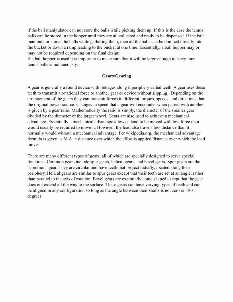
if the ball manipulator can not store the balls while picking them up. If this is the case the tennis balls can be stored in the hopper until they are all collected and ready to be dispensed. If the ball manipulator stores the balls while gathering them, then all the balls can be dumped directly into the bucket or down a ramp leading to the bucket at one time. Essentially, a ball hopper may or may not be required depending on the final design.If a ball hopper is used it is important to make sure that it will be large enough to carry four tennis balls simultaneously.
Gears/Gearing
A gear is generally a round device with linkages along it periphery called teeth. A gear uses these teeth to transmit a rotational force to another gear or device without slipping. Depending on the arrangement of the gears they can transmit forces in different torques, speeds, and directions than the original power source. Changes in speed that a gear will encounter when paired with another is given by a gear ratio. Mathematically the ratio is simply, the diameter of the smaller gear divided by the diameter of the larger wheel. Gears are also used to achieve a mechanical advantage. Essentially a mechanical advantage allows a load to be moved with less force than would usually be required to move it. However, the load also travels less distance than it normally would without a mechanical advantage. Per wikipedia.org, the mechanical advantage formula is given as M.A. = distance over which the effort is applied/distance over which the load moves.
There are many different types of gears, all of which are specially designed to serve special functions. Common gears include spur gears, helical gears, and bevel gears. Spur gears are the “common” gear. They are circular and have teeth that project radially, located along their periphery. Helical gears are similar to spur gears except that their teeth are set at an angle, rather than parallel to the axis of rotation. Bevel gears are essentially conic shaped except that the gear does not extend all the way to the surface. These gears can have varying types of teeth and can be aligned in any configuration so long as the angle between their shafts is not zero or 180 degrees.
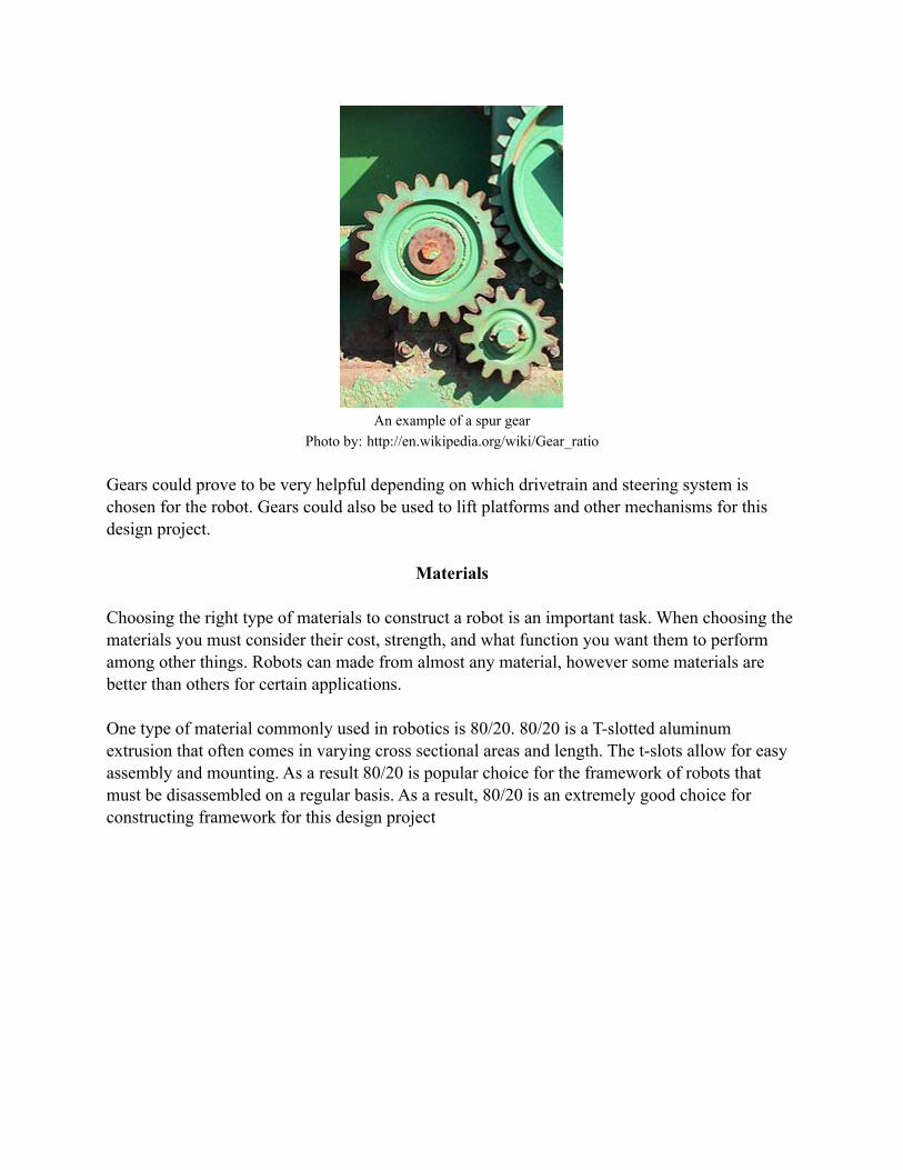
An example of a spur gearPhoto by: http://en.wikipedia.org/wiki/Gear_ratio
Gears could prove to be very helpful depending on which drivetrain and steering system is chosen for the robot. Gears could also be used to lift platforms and other mechanisms for this design project.
Materials
Choosing the right type of materials to construct a robot is an important task. When choosing the materials you must consider their cost, strength, and what function you want them to perform among other things. Robots can made from almost any material, however some materials are better than others for certain applications.
One type of material commonly used in robotics is 80/20. 80/20 is a T-slotted aluminum extrusion that often comes in varying cross sectional areas and length. The t-slots allow for easy assembly and mounting. As a result 80/20 is popular choice for the framework of robots that must be disassembled on a regular basis. As a result, 80/20 is an extremely good choice for constructing framework for this design project

An example of a frame constructed out of 80/20Photo by: http://www.8020.net/T-Slot-1.asp

Another common building material for robots is sheet metal. Sheet metal is strong, light weight, and malleable. This makes it a popular choice when designing ball hoppers, buckets, and ball manipulators.
Although some of the more popular materials have been mentioned here it is important not to limit yourself when choosing building materials. Just because a material costs more doesn’t necessarily make it a better choice. Everything from wood, PVC, and even cardboard have been known to make it into a final design.

Selection of Design Concept
Ball Manipulator
When it comes to the ball manipulator, the most important thing is that it gets the balls, and does so effectively. For this reason, in our consideration, we gave effectiveness the greatest weight. In comparing our designs, all ball manipulators were equal in the way in which they collect the balls, with size being the only exception. In all three designs, the ball manipulator bumps into the pole and allows gravity to bring the ball into the bucket. The difference comes in when we consider the size of the bucket. We considered a larger bucket to be more effective than a smaller bucket. Both Eric and Josh’s design are 12” wide, while Josh’s design is shorter than Eric’s, receiving a lower score. Similarly, Matt’s design is about the length of Eric’s, but four inches shorter, receiving a lower score. The next most important quality of our ball manipulator is the amount of material needed, or size, of the bucket itself. We calculated that for all three designs, the required amount of sheet metal is two square feet and thus, we each received the same score. Moving on, we decided the quality to consider next would be the speed at which the manipulator collects balls. Again, all designs functioning the same, we each received the same score save for Matt, which may require slightly more time lining up the hopper, and thus got a slightly lower score. The last qualifier is cost, which is directly related to size. Since the size was the same for all three designs, and no other factors affected cost, we each received the same score. At the end, after comparing all the qualities and scores, we find that Eric’s design is the best because it provides the most area to collect the balls at the greatest speed.
Ball Hopper
For our ball hopper the design includes all of the components that move the tennis balls from the ball manipulator to the bucket. The first design implemented a linear actuator to lift the ball manipulator up to a ramp located on the top of the robot. Once at the top the balls were to roll out of the back of the manipulator and down the ramp. The ramp then ejected the balls off the side of the robot and into the bucket. The second design employed an almost identical ramp however the ball manipulator was lifted with a rack and pinion design rather than the linear actuator. In this design the balls also exited out of the back of the manipulator. In the third design the ball manipulator is attached to an arm which is attached to a globe motor mounted to the top of the robot. The globe motor then rotated the ball manipulator over the robot. During this rotation the manipulator began to flip upside down until the balls fall out due to gravity and into the bucket. The most important factor was the time to make, in this category the gear and pinion took four hours to create and scored 6/10, the second best was the linear actuator which only took 2 hours to assemble and was used in the final design, the quickest method the rotating arm and dump which is already assembled because it acts as the ball manipulator. Materials required cost nothing for the every design but the gear and pinion which required custom pieces to be bought. Dependability was of high importance and was scored highest with linear actuator design as the

other two allowed for unforeseen error scoring them a 5/10. The gear and pinion method was below the average in ease of implementation and ultimately impractical as the linear actuator used an internal pre-made gear and pinion. Speed was a major factor in our decision process and while the rotating arm and dump was the fastest, we decided that the possibility of error was to great to risk. We ultimately decided on a hybrid method which involved the linear actuator and moving the ramp closer to the bucket, taking a second off the linear actuators time.
Mobile Platform
While considering the platform it was observed that the majority of our cost would be absorbed into the ball manipulator and the assembly of it. Thus, it stood to reason that everything else needed to be cost affective and easily/quickly assembled while, providing as much accessibility given the circumstances. Given the motors we are allowed to use and the strength of the materials provided, consideration to weight was inconsequential. After generating our decision matrixes we found them of little help when it came to platforms. While everyone scored similarly in cost, time to make, and cuts, there were discrepancies in assembly time and strength. While Josh’s appeared to be the weakest, it provided the quickest assembly time. A general trend showed that Eric’s idea appeared the weakest with Matt’s maintaining an eight average, never going below 7, and Josh scored high in every category except strength. While Josh’s platform scored the highest with 7.8 out of 10, the complications in the design proved to be unreasonable when faced with the actual machining of the platform. When the other designs were looked at they showed the vary same problems. Instead, the board was wiped clean and a hybridesque idea was generated which scored a 9.6 out of 10, scoring perfect in every category except strength and time to make (hybrid scored an 8 in strength and 9 in time to make). By creating something that had all the accessibility necessary, was strong, took a little over an hour to create, required no cuts, and is pre-assembled at all times, we freed up much needed time and cut cost to nil. The Picaso is designed to produce the most lightweight yet spacious chassis as possible. By creating a symmetrical design across a vertical center-line, the chassis remains balanced while allowing for considerable weight to be carried. Because the chassis is made of 80/20, vibration is reduced because of the 2 degree drop-off and accessibility is optimized. The versatility of the vertical 80/20 allows wheels to placed anywhere along the edges of the platform in order to compensate for over rotation and necessary angles in other parts.
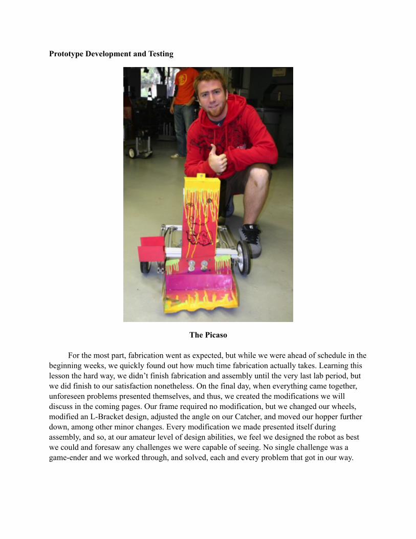
Prototype Development and Testing
The Picaso
For the most part, fabrication went as expected, but while we were ahead of schedule in the beginning weeks, we quickly found out how much time fabrication actually takes. Learning this lesson the hard way, we didn’t finish fabrication and assembly until the very last lab period, but we did finish to our satisfaction nonetheless. On the final day, when everything came together, unforeseen problems presented themselves, and thus, we created the modifications we will discuss in the coming pages. Our frame required no modification, but we changed our wheels, modified an L-Bracket design, adjusted the angle on our Catcher, and moved our hopper further down, among other minor changes. Every modification we made presented itself during assembly, and so, at our amateur level of design abilities, we feel we designed the robot as best we could and foresaw any challenges we were capable of seeing. No single challenge was a game-ender and we worked through, and solved, each and every problem that got in our way.

The Catcher
Initially, the catcher was quite easy to design to specifications but as development progressed, the catcher proved to be a vital part in need of many adjustments. Two such adjustments are discussed in later sections but the major adjustment done to the Catcher was adding an angle to it. Our original documents show the catcher horizontal, but we quickly realized that this design would not allow the balls to escape the bucket. Our solution was to change the angle of the holes through which the bucket attaches to the linear slide. We made this adjustment once, thought we were good and were proved wrong. We again added a steeper angle which finally got the job done. The method of producing the angle was spot welding on a new piece of steel to cover the original holes and then punching new holes at the desired angle. Other adjustments to the bucket were the Retrofit Ball-Liner-Upper and a sheer of one corner.
The Retrofit Ball-Liner-Upper
While practicing, we noticed that our biggest enemy was not friction between the ball and the bucket, but rather between the collected balls. On almost every test, multiple balls would collect near the exit hole and become lodged between themselves and the bucket walls. Our only options were to either increase the exit hole to more then double the size of a tennis ball, or create a piece which had been suggested to us by a fellow student which forces the balls to line up correctly. The choice was obvious when one considers the amount of changes to the overall design needed to increase the size of the exit hole versus the relative ease of bending a small strip of metal. The Retrofit was designed to force incoming balls away from the walls, while funneling the balls towards the exit. Preventing congestion, the design allows a ball to slide off the front piece of the retrofit toward the opposite side of the bucket from the exit. This allowed all the balls to basically form a line and flow out the exit when necessary. v

The Sheer on the Bucket
If, in our final design, the bucket was horizontal and not angled, this sheer would be unnecessary. It was only after we introduced the angle on the bucket that a conflict emerged. The problem was that the hopper needed to be almost touching the bucket in order for the balls to exit, but this new angle on the bucket somewhat reserves a distance to the left of itself (as seen in the image). At first, we tried moving the hopper further away, so that the hopper and its arm don’t hit the bucket while it’s in motion, but the required distance stopped the roll of the tennis-balls during exit. We also tried angling the hopper, trying anything to make the design work as planned. When nothing worked, we ran and got a pair of hand sheers and cut the problematic corner off. This unsightly, but simple, modification was exactly what we needed as it allowed the bucket to rise vertically with no part of it hitting the hopper or its arm.
The Linear Mechanism
The linear mechanism’s purpose was to attach to the linear stabilizer to the frame of the robot. This mechanism also housed the linear slider on its middle 80/20 slot. This slider allowed the bucket to raise and lower smoothly along the linear mechanism. Fabrication was straight forward and simple, no changes were required from the original design. We had no problems with this part, it preformed its task perfectly and dutifully.

The Linear-Stabilizer &Bolt Attachment
While generating our design, we realized that there might be some problems with stability along the linear actuator because of the weight and centrifugal force generated by the rapid turning of differential steering. Thus, we created a piece that allowed the actuator and bucket mount to slide along only a single axis of motion, the Linear-Stabilizer. This custom piece, made of wood, is designed to snugly fit around the actuator, attaching it to the frame and thus stabilizing both the actuator and the linear slide.
With the versatility of the Linear-Stabilizer and the bucket mount, we were able to simply place an undersized bolt connecting the Bucket Mount and the Linear Actuator together without any repercussions. This allowed for extremely easy assembly.
The Custom L-Bracket
In order to mount the base of the linear actuator to the frame we decided to use custom L-brackets. The customization was necessary in order to allow the linear actuator to sit flush on the frame. The changes consisted of the drilling of two close fit 0.2570 inch holes into the bracket. The mill was also used to cut the vertical part of the bracket to the correct size. Some changes were required from the original design in order to provide clearance between the bolt and the 80/20 fasteners. These changes consisted of moving the vertical hole to 0.4088 inches from the horizontal base of the bracket while moving the horizontal hole to 0.7000 inches away from the vertical base. Even with these adjustments the linear actuator did not sit flush with the frame, however they did their job wonderfully as they provided much needed stability to the linear actuator.

The Bucket Mount
The bucket mount was designed to serve as a linkage between the linear actuator and the bucket. It was relatively easy to fabricate as it was made from a sheet of 32-gauge steel and only required two bends. Close fit holes were then drilled to connect it to the bucket and the linear actuator as specified in our Solid Works drawings. It preformed very well, as it had no problem in supporting the weight of our bucket during lifting. It should be noted that during fabrication we decided to omit the gussets from the mount. This was important for two reasons. One, it reduced fabrication time. Two, we noticed that the mount would bow near the large bend if the bucket became caught during lifting or lowering. This was important because it provided warning that something was wrong before failure occurred. This allowed us to make a correction in minutes instead of possible hours if failure had occurred.
The New Seven-Incher
After assembling the robot it was found that only a small amount of the bucket (approximately 1/6”) was capable of maneuvering underneath the 3” ball stands as a result of the steep angle generated. As this was found to be unacceptable, we needed a way to lower the bucket without remaking any pieces. Out of several options, such as increasing the caster wheel, moving the drive wheels forward, and decreasing the diameter of the drive wheels, we decided that decreasing the drive wheel’s diameter was the most manageable of the options and quickest to implement, as we didn’t have to make any new pieces. However, we found that the new wheels were poorly drilled into and were falling apart. So while this could never be a permanent fix, we were confident in its ability to last a week or two.

Discussion / Conclusion
The strongest part of our design is the solid rigidity of the linear slide mechanism. The Linear Slide (80/20 Frame) and the Bucket Mount worked as intended with no adjustments needed. Using an 80/20-brand linear bearing made sliding smooth as butter and so, this was never a complication during assembly. Paired with our linear mechanism, an equally strong aspect of our design was our frame, which was both rigid, and flexible (in that we could change our ideas fluidly). The frame, though, was rather difficult to work with because of the amount of pieces of 80/20 required and the complicated process of attaching brackets to tight corners of the design. On many occasions, the entire team was trying to get a single 80/20 screw to catch. The part of our design which proved to be the weakest was the Catcher, as it performed it’s duty only some of the time, other times it allowed a caught-ball to roll out of the front of it. This unfortunate, seemingly small, oversight resulted in a one-minute penalty multiple times during our runs. Besides this problem, though, the bucket performed the catching beautifully. Our other weakest element was the hopper, which was not flush with the bucket, and so, required the robot to be wiggled when the balls were to exit. The worst aspect of our hopper was it’s flimsiness, both in itself and its attachment. While driving through the tunnel the hoper hit the sidewall and fell out of alignment, resulting in a terrible run. Based on the problem statement and criterion provided, we feel our robot solved the problem well. Our robot did not violate any of the rules and was very capable of picking the tennis balls off the stands. Our design allowed for speed, which was important as time was the standard of evaluation for our robots. As a result of this speed, the robot was sometimes hard to control, which did cause problems during our second run. Also, we made sure that our design remained as simple as possible. By keeping our design simple we were able to cut fabrication time as well as the time required to complete the course. The simplicity of our design also ensured that there were no mechanical failures and any changes that needed to be made could be done so quickly. The hopper was simple by design, however it did not allow the balls to roll into the bucket unless the robot was shaken by the driver. This cost our robot a few seconds, but it turned out not to be a major hindrance. Overall, we feel that we created a very solid design to solve the problem at hand.
After completion of the final design and testing we found there were several things which we would have done differently. The most noticeable of all these things was the size of our catcher. Could we redo the catcher, we would like to make it wider and deeper to prevent balls from spilling out while moving at high speeds. The next most obvious feature that needed modification was the angle of our bucket. While we had decided on an angle based on our 8” diameter wheel design, the angle needed to be greater and tilted toward the exit for the final design which required 7” diameter wheels. Creating this angle initially would have prevented us having to do two major modifications.
Another issue we wished we could have addressed was spacing between the caster wheel and the frame, as well as the spacing between the bracket and the wheel hub. By putting spacers in, we could have reduced friction on the motor mount and not had to force the caster mount over a screw, giving us a cleaner look and more consistent results.
Even though we remained under budget, we could have reduced the amount of 80/20 by 24”, by mounting the computer to the back of the frame, as opposed to placing 2 bars in the middle of the frame for that purpose alone.

Velocity and Turning Radius Calculations
The velocity calculations for various rpm motors and wheel diameters (in inches) are shown below. The no load velocity was calculated by using the formula VNL = RPM/60 * ! * D/12. The load velocity was found using the formula VLoad = VNL * .75. The velocities for our corresponding wheel and motor choices are highlighted in the tables.
No Load Veloctiy (ft/sec) 6.00 10.00 8.00 14.00
44.00 1.15 1.92 1.54 2.69 60.00 1.57 2.62 2.09 3.67 80.00 2.09 3.49 2.79 4.89
150.00 3.93 6.55 5.24 9.16
Load Velocity (ft/sec) = V(No Load) * .75 6.00 10.00 8.00 14.00
44.00 0.86 1.44 1.15 2.02 60.00 1.18 1.96 1.57 2.75 80.00 1.57 2.62 2.09 3.67
150.00 2.95 4.91 3.93 6.87 Since we are using a differential steering system, the turning radius of our robot is the distance from the midpoint between our drive wheels and one of the back corners of the robot. Using the measure feature in Solid Works we found the turning radius to be 14.43”, which is also given below.
Turning Radius: 14.43"

Time Calculation
The drawing above represents our path of choice for completing the course. Below you will find an approximation of the total time required to accomplish this task.
Time Constraints Estimated Time (sec) Distance Entering and Leaving (22 ft) 40 Estimated Distance In Arena (72 ft) 25 Time Required to Gather Each Ball 15x4
Time Required to Dump Balls 30 Total Time 2:35