joining timber rafters - sfs intec · joining timber rafters wt data sheet no.03 3.03 wt convincing...
TRANSCRIPT

Joining timber rafters
WT
Data sheetNo. 03 3.03
WT
Convincing advantages:
n easy designn high performancen rapid assemblyn not visible fastenersn no predrilln no retighteningn ETA-12/0063
EN 1995-1-1
2/6
Function
General information
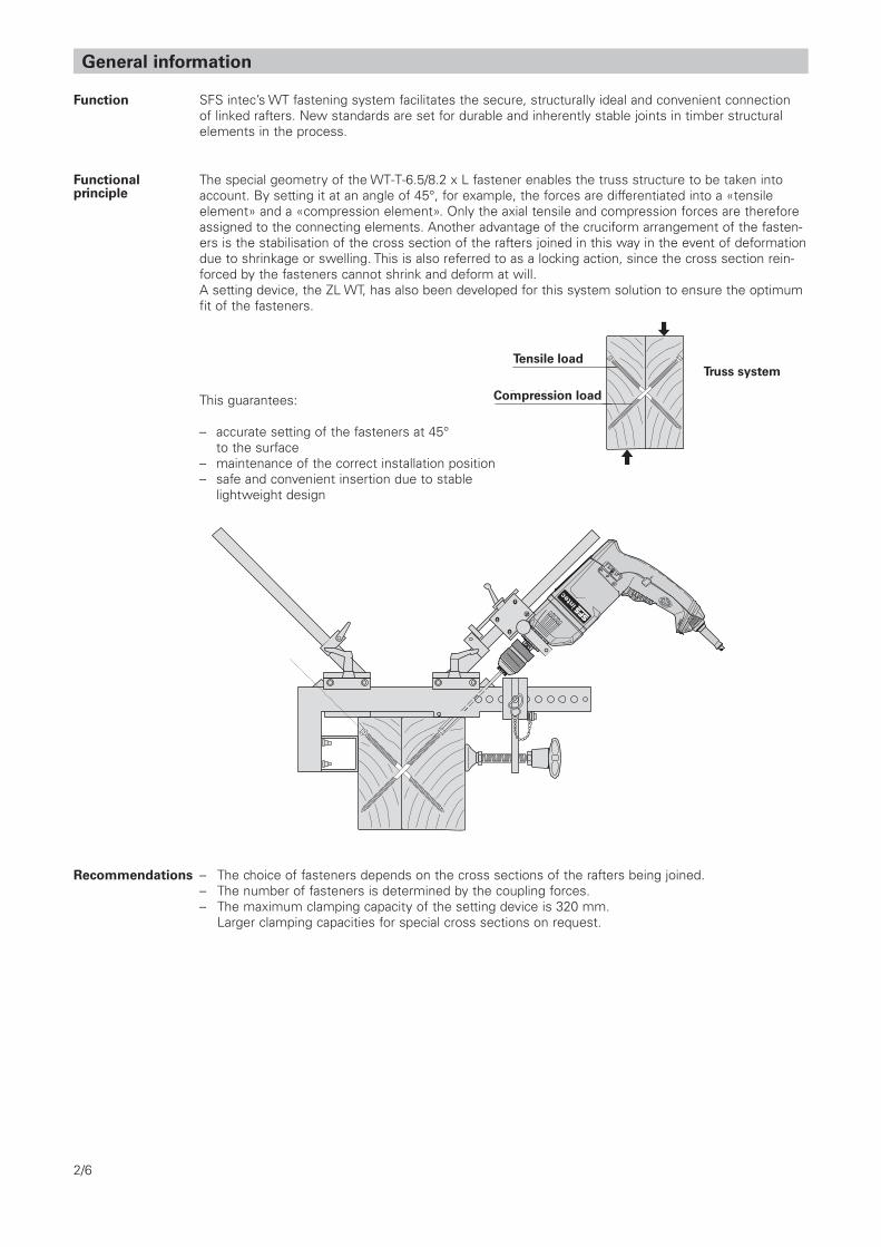
SFS intec’s WT fastening system facilitates the secure, structurally ideal and convenient connection of linked rafters. New standards are set for durable and inherently stable joints in timber structural elements in the process.
Functionalprinciple
The special geometry of the WT-T-6.5/8.2 x L fastener enables the truss structure to be taken into account. By setting it at an angle of 45°, for example, the forces are differentiated into a «tensile element» and a «compression element». Only the axial tensile and compression forces are therefore assigned to the connecting elements. Another advantage of the cruciform arrangement of the fasten-ers is the stabilisation of the cross section of the rafters joined in this way in the event of deformation due to shrinkage or swelling. This is also referred to as a locking action, since the cross section rein-forced by the fasteners cannot shrink and deform at will.A setting device, the ZL WT, has also been developed for this system solution to ensure the optimum fit of the fasteners.
This guarantees:
– accurate setting of the fasteners at 45° to the surface– maintenance of the correct installation position – safe and convenient insertion due to stable lightweight design
FachwerkprinzipZugbelastung
Druckbelastung
– The choice of fasteners depends on the cross sections of the rafters being joined.– The number of fasteners is determined by the coupling forces.– The maximum clamping capacity of the setting device is 320 mm. Larger clamping capacities for special cross sections on request.
Recommendations
R
L
0
>PA6
-GF3
0<
Con t ro l
To r que
Fachwerkprinzip
Tensile load
Compression load
Truss system

3/6
Kd
FK,Rd
<_ 1 or
Kz,d
cos (α) · FK,Rd
<_ 1 or
Ky,d
sin (α) · FK,Rd
<_ 1
Kz,d + Ky,d
(cos (α) + sin (α) ) · FK,Rd
<_ 1
Kd Design value of coupling forceKz,d Design value of coupling force at right angles to the roof surfaceKy,d Design value of the coupling force parallel to the roof surface FK,Rd Design value of the coupling force resistance (see table on page 4)α Roof pitch angle
Defining the fastener
Design proposal
Fastener length L (in mm) depends on width b (7 cm-16 cm) and height h (14 cm-24 cm) of the smaller rafter cross section. The corresponding fastener lengths L are listed as a function of rafter dimensions in the adjoining table.
b
h
b [cm]
h [cm]7 8 9 10 12 14 16
14 160 160 160 160 160 160 160
16 160 190 190 190 190 190 190
18 160 190 220 220 220 220 220
20 160 190 220 245 245 245 245
22 160 190 220 245 275 275 275
24 160 190 220 245 300 300 300
26 160 190 220 245 300 330 330
28 160 190 220 245 300 330 330
Design In the case of only vertical external loading, e.g. inherent load, snow load, the coupling force acts vertically (K = Kv). In each case one of the following must be verified.
α
K zKy
Ky
K
K z
K =
Kv
Lot
α
Ky
Ky
K z
K z
K
K
LotLo
t
s gs c
lam
p
d1
dk
In the case of non-vertical external loading, also combinations with wind loads, the coupling force does not act vertically. Components Kz and Ky must be established and the following verified.
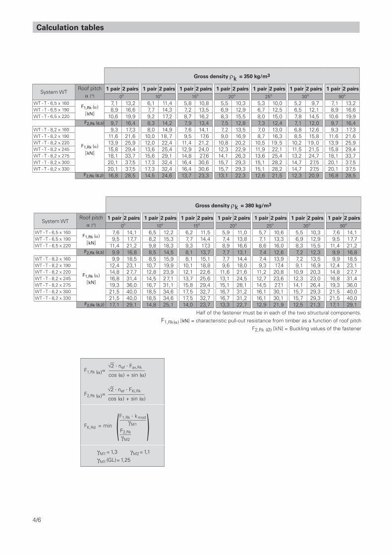
Calculation tables
Gross density rk = 350 kg/m3
System WTRoof pitch
α [o] 1 pair 2 pairs 1 pair 2 pairs 1 pair 2 pairs 1 pair 2 pairs 1 pair 2 pairs 1 pair 2 pairs 1 pair 2 pairs
0o 10o 15o 20o 25o 30o 90o
WT - T - 6,5 x 160F1,Rk (α)
[kN]
7,1 13,2 6,1 11,4 5,8 10,8 5,5 10,3 5,3 10,0 5,2 9,7 7,1 13,2WT - T - 6,5 x 190 8,9 16,6 7,7 14,3 7,2 13,5 6,9 12,9 6,7 12,5 6,5 12,1 8,9 16,6WT - T - 6,5 x 220 10,6 19,9 9,2 17,2 8,7 16,2 8,3 15,5 8,0 15,0 7,8 14,5 10,6 19,9
F2,Rk (6,5) 9,7 16,4 8,3 14,2 7,9 13,4 7,5 12,8 7,3 12,4 7,1 12,0 9,7 16,4WT - T - 8,2 x 160
F1,Rk (α) [kN]
9,3 17,3 8,0 14,9 7,6 14,1 7,2 13,5 7,0 13,0 6,8 12,6 9,3 17,3WT - T - 8,2 x 190 11,6 21,6 10,0 18,7 9,5 17,6 9,0 16,9 8,7 16,3 8,5 15,8 11,6 21,6WT - T - 8,2 x 220 13,9 25,9 12,0 22,4 11,4 21,2 10,8 20,2 10,5 19,5 10,2 19,0 13,9 25,9WT - T - 8,2 x 245 15,8 29,4 13,6 25,4 12,9 24,0 12,3 22,9 11,9 22,1 11,5 21,5 15,8 29,4WT - T - 8,2 x 275 18,1 33,7 15,6 29,1 14,8 27,6 14,1 26,3 13,6 25,4 13,2 24,7 18,1 33,7WT - T - 8,2 x 300 20,1 37,5 17,3 32,4 16,4 30,6 15,7 29,3 15,1 28,2 14,7 27,5 20,1 37,5WT - T - 8,2 x 330 20,1 37,5 17,3 32,4 16,4 30,6 15,7 29,3 15,1 28,2 14,7 27,5 20,1 37,5
F2,Rk (8,2) 16,8 28,5 14,5 24,6 13,7 23,3 13,1 22,3 12,6 21,5 12,3 20,9 16,8 28,5
Gross density rk = 380 kg/m3
System WTRoof pitch
α [o] 1 pair 2 pairs 1 pair 2 pairs 1 pair 2 pairs 1 pair 2 pairs 1 pair 2 pairs 1 pair 2 pairs 1 pair 2 pairs
0o 10o 15o 20o 25o 30o 90o
WT - T - 6,5 x 160F1,Rk (α)
[kN]
7,6 14,1 6,5 12,2 6,2 11,5 5,9 11,0 5,7 10,6 5,5 10,3 7,6 14,1WT - T - 6,5 x 190 9,5 17,7 8,2 15,3 7,7 14,4 7,4 13,8 7,1 13,3 6,9 12,9 9,5 17,7WT - T - 6,5 x 220 11,4 21,2 9,8 18,3 9,3 17,3 8,9 16,6 8,6 16,0 8,3 15,5 11,4 21,2
F2,Rk (6,5) 9,9 16,8 8,5 14,5 8,1 13,7 7,7 13,1 7,4 12,6 7,2 12,3 9,9 16,8WT - T - 8,2 x 160
F1,Rk (α) [kN]
9,9 18,5 8,5 15,9 8,1 15,1 7,7 14,4 7,4 13,9 7,2 13,5 9,9 18,5WT - T - 8,2 x 190 12,4 23,1 10,7 19,9 10,1 18,8 9,6 18,0 9,3 17,4 9,1 16,9 12,4 23,1WT - T - 8,2 x 220 14,8 27,7 12,8 23,9 12,1 22,6 11,6 21,6 11,2 20,8 10,9 20,3 14,8 27,7WT - T - 8,2 x 245 16,8 31,4 14,5 27,1 13,7 25,6 13,1 24,5 12,7 23,6 12,3 23,0 16,8 31,4WT - T - 8,2 x 275 19,3 36,0 16,7 31,1 15,8 29,4 15,1 28,1 14,5 27,1 14,1 26,4 19,3 36,0WT - T - 8,2 x 300 21,5 40,0 18,5 34,6 17,5 32,7 16,7 31,2 16,1 30,1 15,7 29,3 21,5 40,0WT - T - 8,2 x 330 21,5 40,0 18,5 34,6 17,5 32,7 16,7 31,2 16,1 30,1 15,7 29,3 21,5 40,0
F2,Rk (8,2) 17,1 29,1 14,8 25,1 14,0 23,7 13,3 22,7 12,9 21,9 12,5 21,3 17,1 29,1
F1,Rk (α)=
F2,Rk (α)=
FK,Rd = min
gM1= 1,3 gM2= 1,1
√2 . nef . Fax,Rk
cos (α) + sin (α)
F1,Rk . kmodgM1
F2,Rk
gM2( )
√2 . nef . FKi,Rk
cos (α) + sin (α)
4/6
gM1(GL)= 1,25
Half of the fastener must be in each of the two structural components. F1,Rk(α) [kN] = characteristic pull-out resistance from timber as a function of roof pitch
F2,Rk (Ø) [kN] = Buckling values of the fastener

5/6
Basic information on the design aid
The basic principles of calculation in the foregoing design aid are explained below.This information can also be used to calculate coupling points with other roof pitch angles.
Screw forces
Screw 1 is always decisive, i.e. the maximum loading of the coupling point is reached when the tensile force in screw 1 is equal to its load-bearing capacity.
Arrangement
Remarks – Longitudinal forces in linked rafters (e.g. in roof structures) cannot be transferred with this coupling point layout.– Appropriate action must be taken to ensure that the angle of insertion is maintained.– All calculations must be verified and signed off by the planner in charge before the work is performed.
Verification
In the event that a combination of loads arising from loads acting only vertically is applicable, i.e. K acts vertically, the following applie Kz = K · cos (α) Ky = K · sin (α)
α
K z
Ky
Ky
K
K z
K =
Kv
Lot
F1,d
nef · FRd
<_ 1 withkmod · FRk
γMFRd = oder <_ 1
Kz,d + Ky,d
2 · nef · FRd
Proofs for this instance can therefore also be written as follows
cos (α) + sin (α)
2 · nef · FRd
Kd · <_ 1
The verification equation in the case of vertical loading is therefore as follows
with FK,Rd =Kd
FK,Rd<_ 1
nef = n0,9 factor for taking the effectiveness of the fasteners into account nef = 1,0 for a pair of screws nef = 1,87 for two pairs of screws nef = 2,69 for three pairs of screws Fax,Rk characteristic pull-out resistance (see table page 6)
The screws are always arranged to that they cross at half rafter height in the shearing plane between the two rafters.
see table page 4
Kz Ky
Ky, Kz: coupling force in the y and z directionsF1, F2: resulting forces in the screws
The screw forces are the product of:
Kz + Ky
2F1 = (positive tension, negative compression)
Kz – Ky
2F2 =
Combinations
The following values are listed in the load-bearing capacity tables
2 · nef · Fax,Rk
cos (α) + sin (α)F1,Rk =
Solid timber, cross laminated timber C 24 30
Glulam timber GL 24c 28c/24h
Gross density rk [kg/m3] 350 380
WT fastening system High performance for lateral tensile reinforcement
Fastener range:
WT-T-6,5 x LMaterial: carbon steelSurface: DurocoatThread-Ø: 6,5 mm
WT-T-8,2 x LMaterial: carbon steelSurface: DurocoatThread-Ø: 8,2 mm (sg) and Ø 8,9 mm (sclamp)
WT - T - 6,5 x 160 65 65 8,0 T30Fax,Rk [kN]
5,0 5,4WT - T - 6,5 x 190 80 80 8,0 T30 6,3 6,7WT - T - 6,5 x 220 95 95 8,0 T30 7,5 8,0
Fastener range WT-T-6,5 x L / WT-T-8,2 x LType Material
T = carbon steel
Thread-Ød1 [mm]
Length[mm]
sg[mm]
sclamp[mm]
dk
[mm]
Bit Gross density rk [kg/m3]
WT - T - 8,2 x 160 65 65 10,0 T40
Fax,Rk [kN]
6,5 7,0WT - T - 8,2 x 190 80 80 10,0 T40 8,2 8,7WT - T - 8,2 x 220 95 95 10,0 T40 9,8 10,5WT - T - 8,2 x 245 107 107 10,0 T40 11,1 11,9WT - T - 8,2 x 275 122 122 10,0 T40 12,8 13,7WT - T - 8,2 x 300 135 135 10,0 T40 14,2 15,2WT - T - 8,2 x 330 135 135 10,0 T40 14,2 15,2
s gs c
lam
p
d1
dk
More information:If you have any questions aboutfastening technology, just call us.We‘ll be pleased to advise you!
Installation aidsWe offer the appropriate accessories, from the simple, universal gauge to special appliances for specific applications. Our technical consultants will be pleased to help you make the right choice.
Detailed planning documentation cateringfor a very wide range of applications ensures easy, reliable calculation. For special applications our structural timberwork consultants will be pleased to assist you in selecting the most efficient and cost-effective fastening method.
Principles of calculation
350 380
Fax,Rk [kN] = Pull-out resistance from timber
Setting tools and accessories (extract)Application Tools and accessories Fastener Tools and accessories
Main/secondary universal ZL WT/Upurlins, dowelled templatepurlins, prefabricatedbuilding,, etc.
Main/secondary setting tool ZL WT/MSpurlins
Main/secondary purlin support ZL WT/Spurlins
Coupling purlins setting tool ZL WT WT-S/T-6,5 x L Bit T30, length 70, 200, 350 mm WT-T-8,2 x L Bit T40, length 70, 152, 200, 350, 520 mm
WT-S/T-6,5 x L power drill BO 1055WT-T-8,2 x L
WT-S/T-6,5 x L power drill DI 650 L max.: 130 mm
WT-S/T-6,5 x L adapter WT-T40/D10WT-T-8,2 x L adapter WT-T30
DI650
R
L
0
>PA6-GF30<
Control
Torq ue
In t
he e
vent
tha
t an
y di
ffere
nces
exi
st b
etw
een
the
orig
inal
Ger
man
da
ta s
heet
tex
t an
d ve
rsio
ns t
rans
late
d in
to o
ther
lang
uage
s, t
he
orig
inal
Ger
man
tex
t is
the
onl
y va
lid v
ersi
on.
All
calc
ulat
ions
mus
t be
ver
ified
and
sig
ned
off
by t
he p
lann
er
in c
harg
e be
fore
the
wor
k is
per
form
ed. T
he u
ser
is r
espo
nsib
le
for
com
plia
nce
with
the
sta
tuto
ry p
rovi
sion
s.
© S
FS in
tec,
iTW
905
158,
04/
13W
T_03
_EC
5_en
_CH
_Hgg
_3.0
3_Jo
inin
g tim
ber
raft
ers
Tech
nica
l cha
nges
res
erve
dPr
inte
d in
Sw
itrze
rland
Turn ideas into reality.
SFS intec AG / FasteningSystems / CH-9435 Heerbrugg / [email protected] / www.sfsintec.biz