john gerling gerling...
TRANSCRIPT

A Report on the 350Watt Motor Controller
Model FC350BJ/110V
Made byThe Shanghai SIEG Industrial
Companyand Used in Their Line of Mini-Mills
March 2009John Gerling
Gerling Laboratories

Table of Contents
Introduction ……………………………………………………………………… 1
Controllers DiscussedIst Generation – “Daughter Board”…………………………..12nd Generation ………………………………………………………… 13rd Generation – The Current Model ……………………….2
Theory of OperationPower Generation and Control ………………………………… 2Gate Pulse Generation ……………………………………………..2Overload And Interlock Circuits………………………………..3
My Problem Solved .…………………………………………………………. 4
Service Considerations ……………………………………………………..4
SchematicsMain Schematic ……………………………………………………….. 6Low Level Schematic ………………………………………………. 7Operator Control Schematic ……………………………………. 8
PhotographsBottom of Circuit Board W/Component ID’s ………….. 9Top of Circuit Board W/Component ID’s ………………. 10

The SIEG 350 Watt Motor Controller
Introduction - When the motor controller failed in my Grizzly G8689 mini-mill Idecided I would put my engineering background to work and try to fix it myself.
This started me on an odyssey of discovery and effort that resulted in my being able to fixmy controller and left me with a ton of information I decided was worth sharing. Hencethis paper.
I am indebted to Anvio Media for their information on the 1st generation (http://anivo.com/reed/G8689_cont/g8689_cont.htm ) and to Chris Wood of theLittleMachineShop.com ( http://littlemachineshop.com ) who was kind enough to lendme a current model so that I could incorporate that version into this discussion.
Controllers Being Reviewed – There are three models discussed which I refer to as the1st generation, 2nd generation and current – i.e. the model now being sold.
The 1st generation had the low level circuit on a “daughter board’ mounted perpendicularto the main board. It was construction with standard components.
The 2nd generation was redesigned to permit putting all of the circuits on the main boardwithout increasing the size of the board. Unfortunately, this meant going to surfacemount components which makes the board almost impossible to repair if there is a failurein a low level circuit. From a schematic standpoint, it is virtually identical to the 1st
generation. There are a few component changes and relocation, but nothing substantial.This is my controller.
Page 1
The current model is almost identical to the 2nd from a schematic standpoint. Even thepart numbers are the same. The are a number of component changes (single turn trimpots to 10 turn pots e.g.). A major change is the substitution of a 4 pin optocoupler forthe 6 pin version. An important change for the user is the change to a wire insertionterminal board from a spade lug type board. This makes replacement in a mill with spadelug terminated wires somewhat difficult. (more about this later)
Through all of this, SIEG kept the same part number – FC350BJ/110V.
Theory of Operation – The following discussion is based on tests and observations ofmy controller – the 2nd generation. The schematics were carefully checked against theactual circuit. I believe that this information applies to the current model.
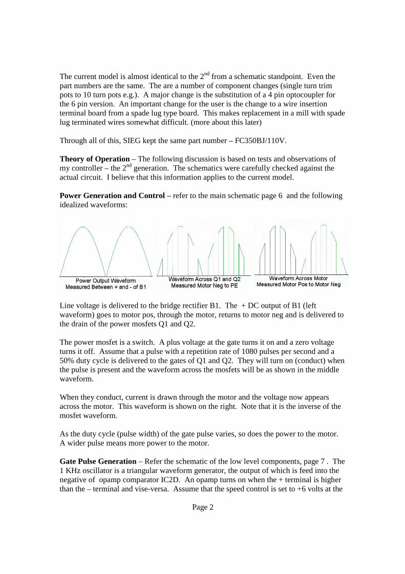
Power Generation and Control – refer to the main schematic page 6 and the followingidealized waveforms:
Line voltage is delivered to the bridge rectifier B1. The + DC output of B1 (leftwaveform) goes to motor pos, through the motor, returns to motor neg and is delivered tothe drain of the power mosfets Q1 and Q2.
The power mosfet is a switch. A plus voltage at the gate turns it on and a zero voltageturns it off. Assume that a pulse with a repetition rate of 1080 pulses per second and a50% duty cycle is delivered to the gates of Q1 and Q2. They will turn on (conduct) whenthe pulse is present and the waveform across the mosfets will be as shown in the middlewaveform.
When they conduct, current is drawn through the motor and the voltage now appearsacross the motor. This waveform is shown on the right. Note that it is the inverse of themosfet waveform.
As the duty cycle (pulse width) of the gate pulse varies, so does the power to the motor.A wider pulse means more power to the motor.
Gate Pulse Generation – Refer the schematic of the low level components, page 7 . The1 KHz oscillator is a triangular waveform generator, the output of which is feed into thenegative of opamp comparator IC2D. An opamp turns on when the + terminal is higherthan the – terminal and vise-versa. Assume that the speed control is set to +6 volts at the
Page 2

plus input of the opamp and that the output of the oscillator goes from 0 to +12 volts.Consider the following idealized wave forms:
The transition level is the same as the voltage on the + input. When the triangle risesabove the transition, the opamp turns off and when it falls below the transition level itturns on. The output of the opamp at pin 14 is as shown.
When the speed control is turned up, the transition point is raised and the pulse width isincreased.
The remainder of the circuitry on this schematic is involved with buffers and the insertionof voltage and current feedback signals.
Now refer back to the main schematic. The PWM signal is delivered to the inputs of theoptocouplers OK1 and OK2. The optocoupler is required because of the voltagedifferences between the ground of the low level circuits and power earth (PE). Thisdevice isolates the two by using an LED to photocouple to a light sensitive diode. Theoutput of the optocoupler is delivered to the gates of the mosfets.
Overload and Interlock Circuits - Refer to the main schematic and to the schematic ofthe operator controls on pages 6 and 8.
Consider the state of the circuits before power is applied. Relays 1,2 and 3 are open andin the state shown. Assume the motor switch is on and that the speed control pot is atzero and the pot switch is closed..
When power is applied, The voltage is applied first through the pot switch. This appliespower to the bridge rectifier and to the low voltage supply. This cause relay 1 and 2 toclose, bypassing the pot switch and delivering power to the motor. Because the powervoltage of a sufficient level is delivered to IC3A, relay 3 stays open. The power pot cannow be advanced and power delivered to the motor.
If an overload occurs, the voltage at IC3A drops and relay R3 is energized removing thecoil voltage to relays 1 and 2 causing them to open. This removes power from B1 andTR1 and causes the yellow overload lamp to go on.
Page 3
The system is reset when the power pot is turned to zero and the switch closed.
My Problem – My problem, after being found, turned out to very simple and easy torepair at no cost.
The two white resistors, R1A and R1B, roughly in the center of the board, are each 0.37ohm 5 watt resistors and are wired in parallel. Current to the motor passes through theseresistors and the voltage across them is used in the current feedback loop. (This explainswhy +12V is tied to the output of B1)
These resistors were mounted on long leads to remove the heat source from the circuitboard. When the mill vibrates, these resistors vibrate, and after a while a lead breaks offat the board. Both of my resistors had broken leads but they were hidden and I neverfound the break until I got to that part of the circuit while measuring each component. Ipulled the resistors, trimmed the leads, resoldered them in place, reinstalled the controllerand got 100% performance.
I note that the leads are much shorter on the current model and I do not anticipate thisproblem reoccurring.
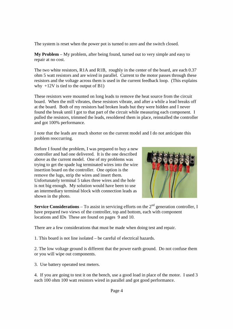
Before I found the problem, I was prepared to buy a newcontroller and had one delivered. It is the one describedabove as the current model. One of my problems wastrying to get the spade lug terminated wires into the wireinsertion board on the controller. One option is theremove the lugs, strip the wires and insert them.Unfortunately terminal 5 takes three wires and the holeis not big enough. My solution would have been to usean intermediary terminal block with connection leads asshown in the photo.
Service Considerations – To assist in servicing efforts on the 2nd generation controller, Ihave prepared two views of the controller, top and bottom, each with componentlocations and IDs These are found on pages 9 and 10.
There are a few considerations that must be made when doing test and repair.
1. This board is not line isolated – be careful of electrical hazards.
2. The low voltage ground is different that the power earth ground. Do not confuse themor you will wipe out components.
3. Use battery operated test meters.
4. If you are going to test it on the bench, use a good load in place of the motor. I used 3each 100 ohm 100 watt resistors wired in parallel and got good performance.
Page 4

5. If you want to look at waveforms, you must use an isolated oscilloscope. I solved theproblem by turning my laptop PC into an oscilloscope using some very sophisticatedsoftware from Germany. www.zeitnitz.de/Christian/Scope/Scope_en.html . The picturesshow the laptop screen and two of the waveforms I recorded. I was not able to get goodpower output shots because the gate pulse frequency was not synchronized with the linefrequency.
6. If you are going to do board repair, make sure that you have a constant temperature(700 F) soldering iron and use solder wick to remove excess solder from the repair point.The board is easily damaged.
Page 5


