john deere 50/60/70/s-series - headsight.com · 3 installation insight® systems insight® box...
TRANSCRIPT

HEADSIGHT.COM | 574.546.5022
Combine Manual09010101k
JOHN DEERE 50/60/70/S-SERIES


i
Copyright Headsight, Inc. 2017
About Headsight
Headsight Contact InfoHeadsight, Inc. 4845 3B Road Bremen, IN 46506 Phone: 574-546-5022 Fax: 574-546-5760 Email: [email protected] Web: www.headsight.com
Technical AssistancePhone: 574-220-5511
About this Manual
How to use this manualThe instructions in this manual are in the order that they should be completed for new installations. Complete all applicable instructions in each section before proceeding. Note that some sections are labeled to indicate they only apply to certain machines or applications. An index is available in the front of the manual to help find technical information for previously installed systems.
This icon designates information of which you should take note.
This icon indicates a special tool needed for a given task.
This icon designates an important instruction.
DisclaimersHeadsight®, Horizon®, Pinpoint®, Insight®, Foresight®, Feathersight® Truesense™ and Truesight® are trademarks of Headsight, Inc. All other trademarks are property of their respective owners.
SuggestionsIf you have any suggestions to improve this manual please call 574-546-5022 or email [email protected].
Headsight’s products are protected by one or more of the following US Patents 6202395, 6833299, 7310931, 7647753, 9609806 and other patents pending.

ii
Table of ContentsAbout Headsight ��������������������������������������������������������������������������������������������� iAbout this Manual ������������������������������������������������������������������������������������������� iInstallation �������������������������������������������������������������������������������������������������� 1
“Basic” Harness Only Systems �������������������������������������������������������������������������� 2Insight® Systems ������������������������������������������������������������������������������������������ 3
Insight® Box Mounting ��������������������������������������������������������������������������������� 3Feathersight® Option Installation (if equipped) ��������������������������������������������������� 4Feathersight® Pressure Sensor Option Installation ���������������������������������������������� 5Magic Power Boost Connectors ����������������������������������������������������������������������� 6
Calibration ��������������������������������������������������������������������������������������������������� 7Setup Insight® Box ���������������������������������������������������������������������������������������� 7Calibrate Insight® ���������������������������������������������������������������������������������������� 7
Standard Calibration ���������������������������������������������������������������������������������� 7Foresight® Calibration (if equipped) ���������������������������������������������������������������� 8Feathersight® Calibration (if equipped) ������������������������������������������������������������ 9
Combine Ground Calibration ��������������������������������������������������������������������������10JD S-Series ����������������������������������������������������������������������������������������������10JD 70-Series ��������������������������������������������������������������������������������������������11JD 50 and 60-Series �����������������������������������������������������������������������������������12
Settings ������������������������������������������������������������������������������������������������������13Combine Settings ����������������������������������������������������������������������������������������13
S-Series Combines �������������������������������������������������������������������������������������1370 Series Combines �����������������������������������������������������������������������������������1360 Series STS Combines ������������������������������������������������������������������������������1350 and 60 Non-STS Series ����������������������������������������������������������������������������14
Insight® Settings �����������������������������������������������������������������������������������������16Tilt Algorithm Selection ������������������������������������������������������������������������������16Tilt Sensitivity �����������������������������������������������������������������������������������������17Feathersight® - HP Balance ��������������������������������������������������������������������������17
Operation ���������������������������������������������������������������������������������������������������18Enabling Height Control �������������������������������������������������������������������������������18
S-Series ��������������������������������������������������������������������������������������������������1850/60/70 Series ���������������������������������������������������������������������������������������19
Overview ����������������������������������������������������������������������������������������������������20Insight® Navigation ��������������������������������������������������������������������������������������20
How to Navigate ����������������������������������������������������������������������������������������20Meaning of Status Light �������������������������������������������������������������������������������20Screen Contrast Adjustment �������������������������������������������������������������������������20Resetting Insight® to Defaults �����������������������������������������������������������������������21Updating Insight® Software with USB Drive �������������������������������������������������������21
Advanced Information ������������������������������������������������������������������������������������22Theory of Operation ������������������������������������������������������������������������������������22Basic Requirements �������������������������������������������������������������������������������������22
iii
Reading Voltages ����������������������������������������������������������������������������������������23Before you Start ���������������������������������������������������������������������������������������23On the Insight® Box������������������������������������������������������������������������������������23S-Series Combines �������������������������������������������������������������������������������������2470 Series Combines �����������������������������������������������������������������������������������2450 and 60 Series Combines ��������������������������������������������������������������������������25
Diagnostics �������������������������������������������������������������������������������������������������26Troubleshooting by Symptom �������������������������������������������������������������������������26Troubleshooting by Insight® Error Codes �����������������������������������������������������������30
Parts ���������������������������������������������������������������������������������������������������������37STATEMENT OF LIMITED WARRANTY �����������������������������������������������������������������38
1
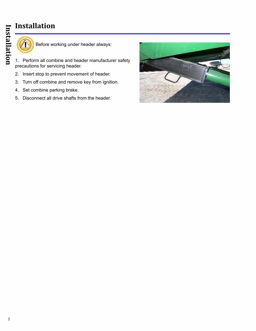
Installation
Installation
Before working under header always:
1. Perform all combine and header manufacturer safety precautions for servicing header.
2. Insert stop to prevent movement of header.
3. Turn off combine and remove key from ignition.
4. Set combine parking brake.
5. Disconnect all drive shafts from the header.
2
Installation
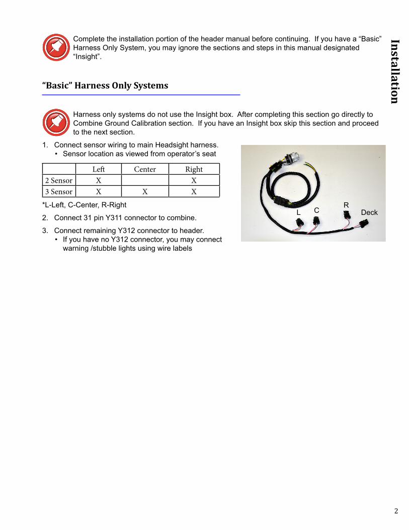
Complete the installation portion of the header manual before continuing. If you have a “Basic” Harness Only System, you may ignore the sections and steps in this manual designated “Insight”.
“Basic” Harness Only Systems
Harness only systems do not use the Insight box. After completing this section go directly to Combine Ground Calibration section. If you have an Insight box skip this section and proceed to the next section.
1. Connect sensor wiring to main Headsight harness.• Sensor location as viewed from operator’s seat
Left Center Right2 Sensor X X3 Sensor X X X
*L-Left, C-Center, R-Right
2. Connect 31 pin Y311 connector to combine.
3. Connect remaining Y312 connector to header.• If you have no Y312 connector, you may connect
warning /stubble lights using wire labels
DeckCLR

3
Installation
Insight® Systems
Insight® Box Mounting
Skip steps 2-4 if the Header manual already had you mount Insight box.
1. Connect Insight box to main Headsight harness.
2. Hold box at rear of header so Headsight harness can reach feeder house electrical connection of combine and mark mounting hole locations.
3. Drill mounting holes using 1/4” drill bit.
4. Secure box to header using hardware provided.
5. Connect sensor wiring to main Headsight harness.• Sensor location as viewed from operator’s seat
Left Left Center Center Right Center Right2 Sensor X X3 Sensor X X X4 Sensor X X X X5 Sensor X X X X X
*L-Left, LC-Left Center, C-Center, RC-Right Center, R-Right
6. Connect 31 pin Y311 connector to combine.
7. Connect remaining Y312 connector to header.• If you have no Y312 connector, you may connect warning /stubble lights using wire labels
RC RCLCL
RL C

4
Installation
Feathersight® Option Installation (if equipped)S550-S670, 70 Series, and 60 Series STS only
1. If combine already has a feederhouse pressure sensor connect “Y” harness in-line with combine feeder house pressure sensor on main valve block.
• If combine does not have a feeder house pressure sensor follow steps in next section
2. Connect harness to sensor
3. Carefully route harness to front of combine near header connector and attach with zip ties.
4. Connect harness to main insight wiring (4 pin, round AMP connector)
S550-S670 70 Series and 60 Series STS only
S680 and S690
1. Route Feathersight harness following existing combine harnesses and hoses from header connector to pressure sensor at valve block just in front of left front tire.
2. Remove factory cover over valve block assembly.
3. Unplug factory harness from pressure sensor and plug in supplied y-harness to sensor.
4. Connect factory wiring to y-harness and Feathersight harness.
5. Connect 4 pin round amp connector to main Insight or Horizon Harness
6. Secure all harnesses with zip ties.
7. Install factory cover over hydraulic valve assembly.

5
Installation
Feathersight® Pressure Sensor Option Installation 50 Series and 60 Series non STS
1. Perform all combine and header manufacturer safety precautions for servicing header.
2. Remove header from combine.
3. Insert stop to prevent movement of header.
4. Release all pressure in hydraulic cylinders.• Lower feeder house against lock and hold button for
10 seconds
5. Turn off combine and remove key from ignition.
6. Set combine parking brake.
7. Disconnect all drive shafts from header.
8. Install pressure sensor in lift port on left hand lift cylinder.
• Remove line from cylinder• Install provided “T” fitting in line• Attach provided pressure sensor• Reattach hydraulic line and ensure o-rings are
properly seated
9. Connect harness to sensor.
10. Carefully route harness to front of combine near header connector attaching with zip ties.
11. Connect harness to main insight wiring (4 pin round AMP connector)

6
Installation
Magic Power Boost Connectors
Your harness may be equipped with Magic Power Boost connectors Y246, Y247 and Y248. If these connectors are present follow the instructions below.
1. For all John Deere Stalkmaster™ 12 row and larger heads connect Y246-Main to Y248-OEM.
2. For all other heads connect Y246-Main to Y247-HS.
7
Calibration
Calibration
Setup Insight® Box
These steps must be performed the first time the Insight box is powered up and each time it is reset. They do not need to be redone each time the Insight box is calibrated. Read the Insight Overview section for basic information about how to use the Insight box.
1. Connect all wiring to Insight box and combine as described in previous section.
2. Start Combine.
3. On the Insight box.• Choose “John Deere”• Choose the “50/60/70/S”• Choose the Header type• Choose the number of height sensors
Calibrate Insight®
When you initialize Insight, you will be led directly to this calibration routine. If you wish to recalibrate at any time - select “>>Perform Calibration” on the Insight main menu.
Standard Calibration
1. Park the combine on a smooth, level surface - preferably a cement driveway or shop floor.
2. Follow on-screen instructions.• “Raise Header” all the way so that NO sensors touch the ground and press enter• “Lower Header” all the way down on the skids and press enter• Go to Combine Ground Calibration section of this manual.
If an error appears on the Insight box - see the Diagnostic section of this manual.

8
Calibration
Foresight® Calibration (if equipped)
Foresight is an optional module to improve the performance of corn systems very near the ground. Each Insight box comes with a 5 hour free trial of Foresight.
1. Park the combine on a smooth, level surface - preferably a cement driveway or shop floor.• If you are unable to find a smooth surface, disable Foresight and perform the standard calibration
2. Adjust the snout tips height.• The snouts should be level across the head and touch the ground at the same point• The snouts should touch the ground when the skid plates are 4-6” off the ground for most headers
3. Enable Foresight on the Insight Box.• Go to >>Setup>>Optional Modules>>Foresight>>Enable Foresight
If you would like to purchase Foresight, contact Headsight.
4. Set the Foresight Gain.• >>Setup>>Optional Modules>>Foresight>>Set Foresight
Gain, in the Insight box• The initial gain setting depends on the header
dimensions. To the right are example settings • For other headers and/or sensor combinations, the
proper setting may be determined by:
Gain = Snout Length
Contact Distance
5. Fine tune the gain setting.• Increase the gain for greater responsiveness near the
ground• Decrease the gain if the header seems jumpy near
the ground ONLY• If the header is jumpy with the points in the air, the
combine needs readjusted NOT Foresight
6. Return to the main menu by pressing escape three times.
7. Select >>Calibration - Follow on-screen instructions.• “Raise Header” all the way so that NO sensors touch the ground and press enter• “Put Snout Tips On The Ground” until they just barely touch the ground and press enter• “Lower Header” all the way down on the skids and press enter• Go to Combine Ground Calibration section of this manual.
If an error appears on the Insight box - see the Diagnostic section of this manual.
Headsight Sensors Wand Length Gain Position 1 (no extension) 3.5 Position 2 3.1 Position 3 2.8 Position 4 (Longest) 2.5

9
Calibration
Feathersight® Calibration (if equipped)Feathersight™ is an optional module to improve the performance of grain systems. It uses both height sensors and the feeder house pressure sensor to allow seamless control from off ground to on ground harvesting.
• Insight automatically enables the pressure sensor when detected during calibration.• If no pressure sensor was detected during calibration, Feathersight is not calibrated or enabled• Pressure sensing may be manually enabled or disabled by selecting >>Setup>>Optional
Modules>>Feathersight>>Feathersight Enable
1. Park the combine on a smooth, level surface - preferably a cement driveway or shop floor.
2. Follow on-screen instructions.• “Raise Header” all the way so that NO sensors touch the ground and press enter• “Lower Head to 4in.” until the skids are 4” off the ground and press enter• “Lower Header” all the way down on the skids and press enter• Go to Combine Ground Calibration section of this manual
If an error appears on the Insight box - see the Diagnostic section of this manual.

10
Calibration
Combine Ground Calibration
A full combine calibration must be completed on new installations or if a component of the header control system is changed on the combine. See combine operators manual for details.
JD S-Series
Press menu.
3. Press combine.
4. Press combine.
5. Press for calibrations.
6. Select Feeder House Raise Speed in calibration box and press
enter.
7. Follow instructions to calibrate and press enter to save calibration.
8. Select Header in calibration box and press enter.
9. Follow instructions to calibrate and press enter to save calibration.
10. For S680 and S690 machines only select Feeder House Tilt Speed
and press enter.
11. Follow instructions to calibrate and press enter to save calibration.
11
Calibration
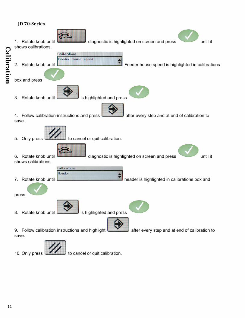
JD 70-Series
1. Rotate knob until diagnostic is highlighted on screen and press until it shows calibrations.
2. Rotate knob until Feeder house speed is highlighted in calibrations
box and press
3. Rotate knob until is highlighted and press
4. Follow calibration instructions and press after every step and at end of calibration to save.
5. Only press to cancel or quit calibration.
6. Rotate knob until diagnostic is highlighted on screen and press until it shows calibrations.
7. Rotate knob until header is highlighted in calibrations box and
press
8. Rotate knob until is highlighted and press
9. Follow calibration instructions and highlight after every step and at end of calibration to save.
10. Only press to cancel or quit calibration.

12
Calibration
JD 50 and 60-Series
1. Press Diagnostics button on cornerpost.
2. Press Up until the screen reads “CAL”.
3. Press Enter.
4. Press Up until the screen reads “Hdr”.
5. Press Enter – screen will read “Hdr – dn”.
6. Lower the header completely to the ground.
7. Press Cal – screen will read “Hdr – up”.
8. Raise the header to the top of its stroke.
9. Press Cal – screen will read “EOC”.
10. Press Enter.
11. Press Esc until returned to the main screen.

13
Settings
Settings
Combine Settings
Properly setting the combine is essential to having responsive header control. You should become very familiar with the steps in this section.
Always perform the combine ground calibration before adjusting settings. Set each sensitivity setting by increasing till header bouncing occurs then decreasing till header becomes stable.
• Set the automatic drop rate to 6-8 seconds from full up to full down in auto mode• Set the automatic raise rate to 5-7 seconds from full down to full up in auto mode• Open hydraulic accumulator• Set height sensitivity• Set tilt sensitivity
S-Series CombinesSet the AHHC height and tilt sensitivity• Press the header button repeatedly until AHHC sensitivity or contour master sensitivity displays.• Use scroll knob to adjust sensitivity.
70 Series CombinesSet the AHHC height and tilt sensitivity • Press the header button repeatedly until AHHC sensitivity or contour master sensitivity displays.• Use scroll knob to adjust sensitivity
60 Series STS CombinesSet the automatic drop rate• Use the knob under the operator’s right-hand armrest.
14
Settings
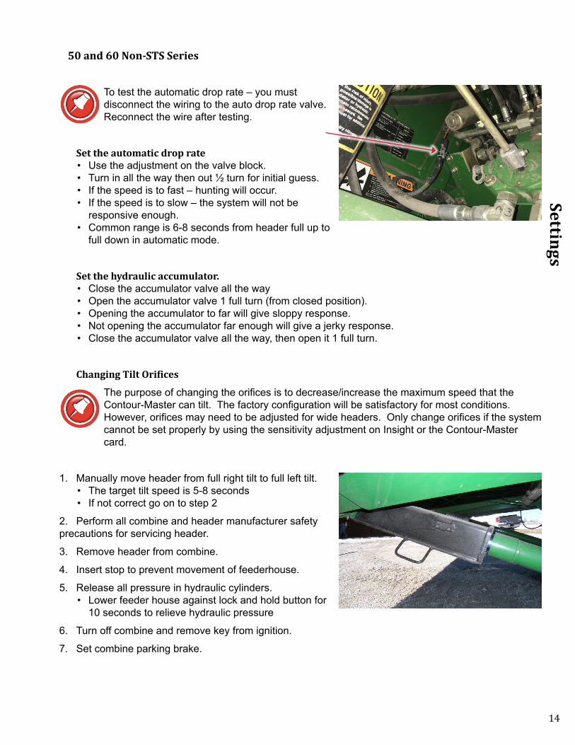
50 and 60 Non-STS Series
To test the automatic drop rate – you must disconnect the wiring to the auto drop rate valve. Reconnect the wire after testing.
Set the automatic drop rate• Use the adjustment on the valve block.• Turn in all the way then out ½ turn for initial guess.• If the speed is to fast – hunting will occur.• If the speed is to slow – the system will not be
responsive enough. • Common range is 6-8 seconds from header full up to
full down in automatic mode.
Set the hydraulic accumulator.• Close the accumulator valve all the way• Open the accumulator valve 1 full turn (from closed position). • Opening the accumulator to far will give sloppy response. • Not opening the accumulator far enough will give a jerky response.• Close the accumulator valve all the way, then open it 1 full turn.
Changing Tilt Orifices
The purpose of changing the orifices is to decrease/increase the maximum speed that the Contour-Master can tilt. The factory configuration will be satisfactory for most conditions. However, orifices may need to be adjusted for wide headers. Only change orifices if the system cannot be set properly by using the sensitivity adjustment on Insight or the Contour-Master card.
1. Manually move header from full right tilt to full left tilt.• The target tilt speed is 5-8 seconds• If not correct go on to step 2
2. Perform all combine and header manufacturer safety precautions for servicing header.
3. Remove header from combine.
4. Insert stop to prevent movement of feederhouse.
5. Release all pressure in hydraulic cylinders.• Lower feeder house against lock and hold button for
10 seconds to relieve hydraulic pressure
6. Turn off combine and remove key from ignition.
7. Set combine parking brake.

15
Settings
8. Using 1/8” allen wrench – remove original orifice from valve block in tilt cylinder supply lines.
• Keep orifice in secure location for later use if needed.
9. If tilt speed is too fast – install an orifice that is smaller than the original orifice removed.
10. If tilt speed is too slow – install an orifice that is larger than the original orifice removed, or remove orifice completely
JD orifice availability:• .26” Z60904 (Original on 50/60 series)• .31” H135777 (Original on 00/10 series)• .46” H149804

16
Installation
Insight® Settings
Tilt Algorithm SelectionHeadsight offers two algorithm choices for controlling lateral tilt. The choice of tilt algorithm is only available for 4 and 5 sensor systems. To change this setting go to >>Setup>>Tilt Options in the Insight menu.
Use 2 sensor tilt (default setting) when harvesting:• Across terraces• Standard conditions
Use 4 sensor tilt when harvesting:• Parallel to terraces• Parallel to ditches• With irrigation tracks
Outer 2 sensor tilt (default setting)• Outer sensor on each side controls lateral tilt• Keeps the outer two sensors the same distance from the ground • All sensors control height• Any sensor can cause the header to raise, all need to agree to lower the header • Keeps the header’s highest point closer to the ground but header may be higher on average
Outer 4 sensor tilt• Outer TWO sensors on EACH side control lateral tilt• Keeps the closest of each outer pair of sensors the same distance from the ground• All sensors control height• Any 1 can raise, all need to agree to lower• Keeps the header closer to the ground on average but may have one end higher

17
Installation
Tilt SensitivityIf the head is too jumpy from side to side – decrease sensitivity. If you would like the head to be more responsive – increase sensitivity. To change this setting go to >>Settings>>Tilt Sensitivity in the Insight™ box. The range is from 5 to 95 with a default setting of 50.
Feathersight® - HP Balance
This setting is only applicable of you have installed and calibrated the optional feathersight module.
1. To change this setting go to >>Setup>>Optional Modules>>Feathersight>>HP Balance in the Insight™ box.
What to know:• This setting is the percentage of the height response determined by the height sensors – as
contrasted with the height response determined by the pressure sensor• Changing this setting will not affect the tilt response• This setting is only available when an auxiliary (pressure) sensor is detected during Insight
calibration • The default value is 65 when an auxiliary (pressure) sensor is detected and 100 if no auxiliary
(pressure) sensor is detected
Setting Hints:• To increase the height response for the height sensors, increase the HP Balance• To increase the height response for the pressure sensor, decrease the HP Balance• If you know that you intend to run with the header always on the ground, you may want to
decrease the HP Balance• If you know that you intend to run with the header always in the air, you may want to increase the
HP Balance or recalibrate Insight® with the pressure sensor disconnected to disable the pressure sensing mode

18
Operation
Operation
After calibrating Insight, operate the Headsight system exactly like you would use a John Deere system.
Enabling Height Control
S-Series
1. Press menu.
2. Press combine.
3. Press combine.
4. Press head.
5. Press to access height control options.
6. Check appropriate box’s.
7. Engage header clutch .
8. Press 2 or 3 resume button on hydro handle to engage AHHC.
9. Turn the AHC dial on the armrest with header control engaged.• Clockwise = higher• Counter-clockwise = lower

19
Operation
50/60/70 Series
1. Press on cornerpost to enable the icon.
2. Press on cornerpost to enable the icon.
3. Engage header clutch.
4. Ensure that the header float option is disabled
5. Press 2 or 3 resume button on hydro handle to engage AHHC.
6. Turn the AHC dial on the armrest with header control engaged.• Clockwise = higher• Counter-clockwise = lower

20
Overview
Overview
Insight® Navigation
How to NavigateWhen in a menu (selection arrow appears to left side)
• Enter: chooses the selected menu choice• Esc: backs up one menu level• Up: moves up within the menu choices displayed • Down: moves down within the menu choices displayed
When in a screen which allows setting of parameters• Enter: backs up to last menu level AFTER saving• Esc: backs up to last menu level without saving• Up: increases the value• Down: decreases the value
Meaning of Status LightSolid Green:
• System is operating• No errors detected
Solid Red:• System is NOT operating• No height or tilt signals are sent to combine• You have changed settings which require calibration of Insight, are currently in a menu which will
force a calibration if you make any changes, or are in calibration mode
Solid Green with Flashing red:• System is operating• An error has been detected• Repair problem then clear errors
Flashing Red:• System is operating• A sensor has been ignored• See note in Troubleshooting by Error - ER16• Repair system - Recalibrate Insight
Screen Contrast AdjustmentTo increase contrast:
• Press and hold Esc +• Press Up to increase contrast (while holding Esc)
To decrease contrast:• Press and hold Esc +• Press Down to decrease contrast (while holding Esc)

21
Overview
Resetting Insight® to DefaultsTo reset all settings hold + for 5 seconds:
• Press and hold ESC then• Press and hold Enter while holding Esc• Hold both for 5 seconds
Updating Insight® Software with USB DriveUpdating software may cause the Foresight option to be disabled. If you have purchased Foresight, contact Headsight before updating software.
1. You will need:• USB drive• Means of loading USB Stick (computer with USB)
2. Load USB drive with new software files• Place insightf.hex in the root directory of USB drive (ex. E:\insightf.hex) • Do not change file names
3. If you do not have the new files you may• Download updated software from www.headsight.com • Order pre-loaded USB drive from Headsight, Inc.
4. Remove cap from USB on front of Insight controller
5. Insert USB drive card into USB slot on front of Insight
6. Power Insight• Turn on key switch
7. Wait for software to download• Yellow light will blink while download is in progress• Green light will turn on solid when download is complete
8. Verify update is successful• Go to >>About Insight>>Software Version and read software version number
9. Remove USB drive
10. Install cap on USB on front of Insight controller
11. Remove power from Insight• Turn off key

22
Advanced Info
Advanced Information
Theory of Operation
A review of the following points will help the service technician to understand the complete system which will help diagnosing specific problems.
1. Each sensor returns a variable voltage depending on header height.• High header height = high voltage (approximately 4 volts)• Low header height = low voltage (approximately 1 volt)
2. Each sensor has 3 wires:• A: blue = ground• B: white = signal returned to combine (varies1-4 volts)• C: pink = 5 volt power
3. The Insight box adjusts signals as needed then sends them to combine using the same combine wiring as OEM system would use.
• All sensors are scaled to an appropriate range for combine • Insight will reverse the direction of swing if needed• Insight box reads all sensors and sends signals to combine that will cause appropriate height and
or tilt response • If Foresight is enabled - the Insight box magnifies the voltage change below the point where the
snout tips touch the ground
4. The voltages the combine sees are exactly like what it would see with an OEM system. All existing combine controls and settings may be used.
Basic Requirements
Each sensor must meet basic requirements for the combine to accept the calibration. If any sensor does not meet the requirements below you must correct it (to meet the requirements) and then recalibrate the Insight box. See the header manual for sensor adjustment instructions.
• Sensor output voltage must always be between .3 and 4.7 volts.• Sensor output voltage must change more than 1.0 volts from raised to lowered position for each
sensor.

23
Advanced Info
Reading Voltages
Before you Start
The Insight box can display both the input voltages it receives from each sensor and the output voltages it is sending to the combine.
Sensor voltage = Insight box input voltage Insight box output voltage = Combine sensor input
On the Insight® Box1. From main menu, go to >> Diagnostics>>Disp Sensor Voltages
• This shows real-time voltage coming from each sensor.
2. For more information about sensor history and status see >>Diagnostics>>Detailed Diagnostics>>(parameter of interest)
• Sensor = signal from sensor in volts• Max = the maximum voltage sent to Insight box from sensor since last calibrated• Min = the minimum voltage sent to Insight box from sensor since last calibrated• Enabled = is this sensor enabled to control height? Yes or No• SetH = the “header raised” voltage set-point recorded during calibration• SetL = the “header lowered” voltage set-point recorded during calibration• Reversed = is the polarity of this sensor reversed? Yes or No
3. To read the Insight output voltages the combine receives, see >>Diagnostics>>Detailed Diagnostics>>(parameter of interest).
• Left Height Output• Right Height Output
Sensor Voltages
L LC CTR RC R0.0 0.0 0.0 0.0 0.0
Left Sens =0.00VMax=0.00V SetH=5.00VMin=0.00V SetL=0.00VEnabled=N Reversed=N
Insight box scales voltages received to what combine needs to function

24
Advanced Info
S-Series Combines
1. Press menu.
2. Press message center
3. Press addresses.
4. Select LC1 in devices box.
5. Press arrow down till you see address 21-Left, 22-center, 24-right
70 Series Combines
1. Press menu.
2. Scroll to when highlighted press
3. Scroll to when highlighted press
4. Scroll to when highlighted press
5. Scroll to when highlighted and press
6. Scroll to when highlighted and press untill desire address is displayed.
7. Address 28 left, 29 center, and 30 right voltage.

25
Advanced Info
50 and 60 Series Combines
1. Press Diagnostics button on cornerpost.
2. Press Up until the screen reads “E01”.
3. Press Enter.
4. Press Up until you see address 22-Left, 24-center, 26-right
26
Diagnostics
Diagnostics
Troubleshooting by Symptom
Nearly every problem with the header control system on JD combines may be resolved by one of the following simple steps:
• Make sure each sensor meets basic requirements discussed in Advanced Info section• Properly calibrate Insight box• Properly calibrate combine• Enable appropriate HHC functions• Properly set combine electronics and/or hydraulics
Symptom Problem SolutionHeader is too jumpy or responds too slowly
Calibration is not properly completed
Combine is improperly set
Recalibrate Insight box and combine
See Combine Setting Section
Combine quick calibration fails Insight is not properly calibrated
Header is not properly connected
Insight box detected an error
Full calibration required
Combine does not recognize header.
Verify all sensors are free to move through full range during calibration
Verify that sensors swing through similar range during Insight calibration and combine calibration
Verify all combine harnesses are properly connectedCycle key switch off – on then recalibrate
Repair error, clear error codes on InsightCycle key switch off – on then recalibrate
Make sure to fully lower the feeder house
Verify that 50/60/70/S is chosen on the Insight box and that a header type has been selected
27
Diagnostics
Symptom Problem SolutionCannot operate header low enough
Calibration not properly completed
Perform combine Full-Cal, Quick Cal or Header Cal
Contact Headsight for information regarding optional products Foresight and/or Feathersight.
Cannot operate header high enough.
Calibration not properly completed
Perform combine Quick-Cal or Header Cal
For corn heads: verify that the extensions are installed at the proper position.
No automatic operation – height or tilt
Wiring is not connected properly or calibration has not been completed.
Header control is not enabled with cab controls.
Insight settings or calibration incorrect.
Power supply from combine less than 11V to Insight.
Insight box needs to be reset
Insight box/wiring failure
Combine problem
See Installation/Calibration section of manual
See Operation section for instructions about how to enable.
Verify that the proper combine and header type have been selected.Redo “Perform Calibration” on Insight box
Measure power supply voltage with key on.Pin 4 of connector Y101 on Insight boxPin 4 of header connector Y311
See Insight Overview for details.
Read sensor input values on combine monitorSee “Reading Voltages” section
Measure voltage on pins 7,3 and 9 of header connector with key on.All values should be approximately 4V with header raised – 1V with header lowered.
Contact your JD service technician
28
Diagnostics
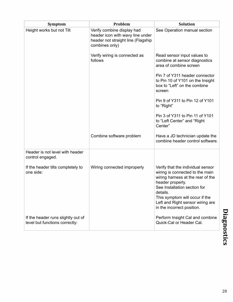
Symptom Problem SolutionHeight works but not Tilt Verify combine display had
header icon with wavy line under header not straight line (Flagship combines only)
Verify wiring is connected as follows
Combine software problem
See Operation manual section
Read sensor input values to combine at sensor diagnostics area of combine screen
Pin 7 of Y311 header connector to Pin 10 of Y101 on the Insight box to “Left” on the combine screen
Pin 9 of Y311 to Pin 12 of Y101 to “Right”
Pin 3 of Y311 to Pin 11 of Y101 to “Left Center” and “Right Center”
Have a JD technician update the combine header control software.
Header is not level with header control engaged.
If the header tilts completely to one side:
If the header runs slightly out of level but functions correctly:
Wiring connected improperly Verify that the individual sensor wiring is connected to the main wiring harness at the rear of the header properly. See Installation section for details.This symptom will occur if the Left and Right sensor wiring are in the incorrect position.
Perform Insight Cal and combine Quick-Cal or Header Cal.

29
Diagnostics
Symptom Problem SolutionDisplay dim, blank, or hard to read
Screen contrast improperly adjusted
Weak power supply to Insight™ box
Short in sensors powered by Insight box
Control box failure
See Insight Settings
Measure supply voltage with Insight connected – some combines do not maintain enough power under electrical load. Examples of causes for weak power supply includeEngine startupEngaging an electric feeder reverser
Insight will need reset after correction of wiring short
Reversed polarity to hall-effect sensors may cause this symptomIndividually disconnect sensors to isolate problem – screen will regain contrast when faulty sensor is disconnected
Correct short in wiring
Insight will need reset after correction of wiring short
Contact HeadsightInsight box does not power up Power wire needs to be in pin 31
of connector Y311 for Headsight systems made before 2008
Control box failure
Move Headsight combine power wire from pin 29 to pin 31
Measure voltage across pin 4 (power) and pin 6 (ground) of y101 on Insight box.

30
Diagnostics
Troubleshooting by Insight® Error Codes
Error Code Problem SolutionER11
Left sensor signal less than 0.3VLeft sensor temporarily disconnected.
Wiring open
Sensor failure
Repair wiring or bad connectorCalibrate Insight BoxCalibrate Headsight BoxCalibrate Combine
Check sensor harness for pinched/broken wiring
See sensor test instructionsER12
Left sensor signal greater than 4.7V
Wiring problem
Sensor failure
Ground wire to sensor is openSignal short to powerCalibrate Insight BoxCalibrate Headsight BoxCalibrate Combine
See sensor test instructionsER13
Left sensor swing less than 0.6VLeft sensor mechanical range is restricted
Sensor failure
Verify sensor is not obstructed in swingVerify sensor can collapse fully with header loweredAdjust down stop to allow greater range
See sensor test instructionsER16
Left sensor expected but not detected
Left sensor not properly connected
Not enough swing during cal
Incorrect number of sensors selected in setup
Sensor failure
Control box /wiring failure
Verify harness is connected to sensor 1Verify harness is connected properly to control box harnessVerify that signal wire (Pin B white wire of sensor cable) is connected to PIN7 of connector Y101 (Insight box)
Make sure sensor meets requirements in - Advanced Information - Basic Requirements section of this manual
Go to >>Initial Setup>>Number Sensors and choose the correct number of sensors
See sensor troubleshooting instructions
Contact Headsight

31
Diagnostics
Error Code Problem SolutionER17
Left sensor detected but not expected
Incorrect number of sensors selected in setup
Harness wiring error
Control box /wiring failure
Go to >>Setup>>System Select and choose the correct number of sensors
Verify that no wires contact PIN7 of connector Y101
Contact HeadsightER21
Left Center sensor signal less than 0.3V
Left Center sensor temporarily disconnected.
Wiring open
Sensor failure
Repair wiring or bad connectorCalibrate Insight BoxCalibrate Headsight BoxCalibrate Combine
Check sensor harness for pinched/broken wiring
See sensor test instructionsER22
Left Center sensor signal greater than 4.7V
Wiring problem
Sensor failure
Ground wire to sensor is openSignal short to powerCalibrate Insight BoxCalibrate Headsight BoxCalibrate Combine
See sensor test instructionsER23
Left Center sensor swing less than 0.6V
Left Center sensor mechanical range is restricted
Sensor failure
Verify sensor is not obstructed in swingVerify sensor can collapse fully with header loweredAdjust down stop to allow greater range
See sensor test instructions
32
Diagnostics
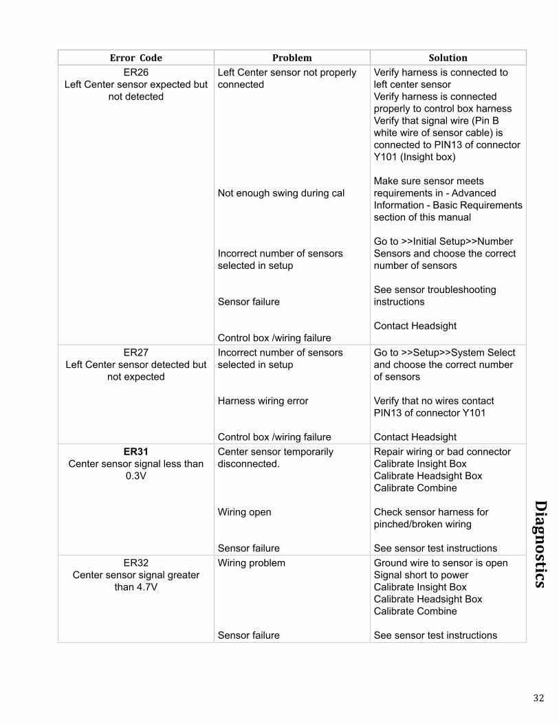
Error Code Problem SolutionER26
Left Center sensor expected but not detected
Left Center sensor not properly connected
Not enough swing during cal
Incorrect number of sensors selected in setup
Sensor failure
Control box /wiring failure
Verify harness is connected to left center sensorVerify harness is connected properly to control box harnessVerify that signal wire (Pin B white wire of sensor cable) is connected to PIN13 of connector Y101 (Insight box)
Make sure sensor meets requirements in - Advanced Information - Basic Requirements section of this manual
Go to >>Initial Setup>>Number Sensors and choose the correct number of sensors
See sensor troubleshooting instructions
Contact Headsight
ER27Left Center sensor detected but
not expected
Incorrect number of sensors selected in setup
Harness wiring error
Control box /wiring failure
Go to >>Setup>>System Select and choose the correct number of sensors
Verify that no wires contact PIN13 of connector Y101
Contact HeadsightER31
Center sensor signal less than 0.3V
Center sensor temporarily disconnected.
Wiring open
Sensor failure
Repair wiring or bad connectorCalibrate Insight BoxCalibrate Headsight BoxCalibrate Combine
Check sensor harness for pinched/broken wiring
See sensor test instructionsER32
Center sensor signal greater than 4.7V
Wiring problem
Sensor failure
Ground wire to sensor is openSignal short to powerCalibrate Insight BoxCalibrate Headsight BoxCalibrate Combine
See sensor test instructions

33
Diagnostics
Error Code Problem SolutionER33
Center sensor swing less than 0.6V
Center sensor mechanical range is restricted
Sensor failure
Verify sensor is not obstructed in swingVerify sensor can collapse fully with header loweredAdjust down stop to allow greater range
See sensor test instructionsER36
Center sensor expected but not detected
Center sensor not properly connected
Not enough swing during cal
Incorrect number of sensors selected in setup
Sensor failure
Control box /wiring failure
Verify harness is connected to sensor 1Verify harness is connected properly to control box harnessVerify that signal wire (Pin B white wire of sensor cable) is connected to PIN8 of connector Y101 (Insight box)
Make sure sensor meets requirements in - Advanced Information - Basic Requirements section of this manual
Go to >>Initial Setup>>Number Sensors and choose the correct number of sensors
See sensor troubleshooting instructions
Contact Headsight
ER37Center sensor detected but not
expected
Incorrect number of sensors selected in setup
Harness wiring error
Control box /wiring failure
Go to >>Setup>>System Select and choose the correct number of sensors
Verify that no wires contact PIN8 of connector Y101
Contact HeadsightER41
Right Center sensor signal less than 0.3V
Right Center sensor temporarily disconnected.
Wiring open
Sensor failure
Repair wiring or bad connectorCalibrate Insight BoxCalibrate Headsight BoxCalibrate Combine
Check sensor harness for pinched/broken wiring
See sensor test instructions

34
Diagnostics
Error Code Problem SolutionER42
Right Center sensor signal greater than 4.7V
Wiring problem
Sensor failure
Ground wire to sensor is openSignal short to powerCalibrate Insight BoxCalibrate Headsight BoxCalibrate Combine
See sensor test instructionsER43
Right Center sensor swing less than 0.6V
Right Center sensor mechanical range is restricted
Sensor failure
Verify sensor is not obstructed in swingVerify sensor can collapse fully with header loweredAdjust down stop to allow greater range
See sensor test instructionsER46
Right Center sensor expected but not detected
Right Center sensor not properly connected
Not enough swing during cal
Incorrect number of sensors selected in setup
Sensor failure
Control box /wiring failure
Verify harness is connected to sensor 1Verify harness is connected properly to control box harnessVerify that signal wire (Pin B white wire of sensor cable) is connected to PIN14 of connector Y101 (Insight box)
Make sure sensor meets requirements in - Advanced Information - Basic Requirements section of this manual
Go to >>Initial Setup>>Number Sensors and choose the correct number of sensors
See sensor troubleshooting instructions
Contact Headsight
ER47Right Center sensor detected but
not expected
Incorrect number of sensors selected in setup
Harness wiring error
Control box /wiring failure
Go to >>Setup>>System Select and choose the correct number of sensors
Verify that no wires contact PIN14 of connector Y101
Contact Headsight

35
Diagnostics
Error Code Problem SolutionER51
Right sensor signal less than 0.3V
Left sensor temporarily disconnected.
Wiring open
Sensor failure
Repair wiring or bad connectorCalibrate Insight BoxCalibrate Headsight BoxCalibrate Combine
Check sensor harness for pinched/broken wiring
See sensor test instructionsER52
Right sensor signal greater than 4.7V
Wiring problem
Sensor failure
Ground wire to sensor is openSignal short to powerCalibrate Insight BoxCalibrate Headsight BoxCalibrate Combine
See sensor test instructionsER53
Right sensor swing less than 0.6V
Right sensor mechanical range is restricted
Sensor failure
Verify sensor is not obstructed in swingVerify sensor can collapse fully with header loweredAdjust down stop to allow greater range
See sensor test instructionsER56
Right sensor expected but not detected
Right sensor not properly connected
Not enough swing during cal
Incorrect number of sensors selected in setup
Sensor failure
Control box /wiring failure
Verify harness is connected to sensor 1Verify harness is connected properly to control box harnessVerify that signal wire (Pin B white wire of sensor cable) is connected to PIN9 of connector Y101 (Insight box)
Make sure sensor meets requirements in - Advanced Information - Basic Requirements section of this manual
Go to >>Initial Setup>>Number Sensors and choose the correct number of sensors
See sensor troubleshooting instructions
Contact Headsight

36
Diagnostics
Error Code Problem SolutionER57
Right sensor detected but not expected
Incorrect number of sensors selected in setup
Harness wiring error
Control box /wiring failure
Go to >>Setup>>System Select and choose the correct number of sensors
Verify that no wires contact PIN9 of connector Y101
Contact HeadsightER61
Sensor 6 (aux sensor) signal less than 0.3V
Wiring open
Sensor failure
Check sensor harness for pinched/broken wiring
See sensor test instructionsER62
Sensor 6 (aux sensor) signal greater than 4.7V
Wiring problem
Sensor failure
Ground wire to sensor is open
See sensor test instructions

37
Parts
Parts
ITEM QTY. PART NUMBER DESCRIPTION1 AR INSIGHT Insight Control Box2 AR QC5-JD73-04
HC3-JD53-304HC3-JD63-04
QJ5-JD63-31Q
Insight HarnessInsight HarnessInsight HarnessInsight Harness
3 ARAR
HT225208100108
Single Point CoverSnap Ring
4 ARAR
HT2250B2250
BracketBracket Hardware Kit
*all parts vary for each application, please call
for more information
1 2
34

38
STATEMENT OF LIMITED WARRANTY
For Headsight® Products Headsight Inc. (Headsight) warrants its new products to be free from defects in material and workmanship for a period of twelve (12) consecutive months following the date of purchase by the retail purchaser.
Headsight Inc. (Headsight) warrants its new corn sensors assemblies for a period of thirty-six (36) months.
Headsight warrants genuine Headsight replacement parts and components to be free from defects in material and workmanship for a period of six (6) consecutive months following the date of purchase or the remainder of the original equipment warranty period, whichever is longer.
Headsight’s obligation under these warranties shall be limited to repairing or replacing, free of charge to the original purchaser, any part that, in Headsight’s judgment, shows evidence of such defect.
Limitations to Warranty
This warranty does not cover:• Warranty claims directly resulting from improper installation of the product.• Any product damaged by accident, abuse, misuse, or negligence after shipment from Headsight.• Any unauthorized product alteration or modification.• Any unauthorized repairs made with parts other than genuine Headsight parts.• Any repairs performed by anyone other than Headsight or an authorized Headsight dealer unless specifically authorized
by Headsight.
Warranty Procedure• Troubleshooting should be done between farmer/dealer and Headsight through our technical assistance @
574.220.5511. • Labor reimbursement will occur only pre-arranged through Headsight technical assistance and be scheduled to a flat rate
basis or reasonable time allowance in Headsight’s judgment. • There is no mileage reimbursement. • Diagnostic time will not be reimbursed except in pre-arranged circumstances.• Warranty claims should be on typical dealer service work order with a number and name to be attached for any future
correspondence. • All warranty work must be performed, and claims submitted, within thirty (30) days of the occurrence of the claim and
within the warranty period.• All parts removed during warranty repair must be returned to Headsight with Headsight’s Return Form within thirty (30)
days of the occurrence of the claim and within the warranty period.• Headsight, Inc. reserves the right to either inspect the product at the original retail purchaser’s location or require it to be
returned to Headsight, Inc. for inspection.
Limitation of LiabilityHeadsight makes no express warranties other than those, which are specifically described herein. Any description of the goods sold hereunder, including any reference to buyer’s specifications and any descriptions in circulars and other written material published by Headsight is for the sole purpose of identifying such goods and shall not create an express warranty that the goods shall conform to such description.
THIS WARRANTY IS EXPRESSLY IN LIEU OF ALL OTHER WARRANTIES EXPRESSED OR IMPLIED. There are no implied warranties of merchantability or fitness of a particular purpose. This warranty states Headsight’s entire and exclusive liability and buyer’s exclusive remedy or any claim for damages in connection with the sale of furnishing of Headsight products, their design, suitability for use, installation or operation, or for any claimed defects herein. HEADSIGHT WILL IN NO EVENT BE LIABLE FOR ANY INCIDENTAL OR CONSEQUENTIAL DAMAGES WHATSOEVER, NOR FOR ANY SUM IN EXCESS OF THE PRICE RECEIVED FOR THE GOODS FOR WHICH LIABILITY IS CLAIMED.
No representative of Headsight nor any dealer associated with Headsight has the authority to change the items of this warranty in any manner whatsoever, and no assistance to purchaser by Headsight in the repair of operation of any Headsight product shall constitute a waiver of the conditions of this warranty, nor shall such assistance extend or revive it.
Headsight reserves the right to make improvements in design or changes in specifications at any time, without incurring any obligation to owners of units previously sold. Warranty: 1/2017

P 574.546.5022 • F 574.546.57604845 3B Rd • Bremen, IN [email protected]