job no. sheet no. rev. consulting e n g i n e e r s · job no. sheet no. rev. job title xx ms1553...
TRANSCRIPT

Job No. Sheet No. Rev.
Job Title
XX
MS1553
Wind Induced (Static) Along-Flow Drag and (Dynamic) Along-Flow Gust Pressure Definition
Design overall building net drag pressure, pbuilding = 1.81 ⇒ 1.81 kPa cl.2.5.2
p building = p windward + p leeward ≥ 0.65 kPa
Design windward wall net drag pressure, pwindward = 0.28 ⇒ 0.65 kPa cl.2.4.1
Design leeward wall net drag pressure, pleeward = 1.53 ⇒ 1.53 kPa cl.2.4.1
Design internal wall net drag pressure, pinternal = 0.78 kPa cl.2.4.1
Dynamic pressure, qs = 0.5ρair.Vdes2 = 0.613Vdes
2 = 1.29 kPa cl.2.4.1
Design (3s-gust) wind speed at z, Vdes = 45.9 m/s cl.2.4.1
Design (3s-gust) wind speed at z=h, Vdes,z=h = 45.9 m/s cl.2.4.1
Site (3s-gust) wind speed, Vsit = 45.9 m/s cl.2.2
Height from the ground to the top of the structure, ht = 154.3 m OK
Average roof height of the structure above ground, h = 154.3 m OK
Breadth of the structure on plan normal to wind stream, b = 55.0 m
Depth of the structure on plan parallel to wind stream, d = 35.0 m
Height on structure above local ground level, z = 154.3 m OK
Station (3s-gust) wind speed, VS = 33.5 m/s T.3.1
Note V s is the 3s-gust wind speed for a 50-years return period;
Note that although the overall building net aerodynamic shape factor is 1.30 based on T.5.2: −
(a) that for an enclosed building roof could be -2.60 (upward) to 1.00 (downward) based
on T.5.3(b) (adopting -1.30 and 0.50) and T.5.1(b) (adopting 1.00C pe as internal,
thus effectively doubling the C pe ), additionally K l for cladding may apply;
Design upward roof net drag pressure, p upward = -3.36 K l kPa
Design downward roof net drag pressure, p downward = 1.29 K l kPa
(b) that for an attached canopy roof could be -1.50 (upward) to 1.20 (downward) based
on T.D8, additionally K l for cladding may apply;
Design upward canopy net drag pressure, p upward = -1.94 K l kPa
Design downward canopy net drag pressure, p downward = 1.55 K l kPa
(c) that for a hoarding or free standing wall could be 3.00 based on T.D2(c), with the
local pressure factor, K l for cladding not being applicable based on D2.1;
Design overall hoarding net drag pressure, p hoarding = 3.88 kPa
(d) that for an enclosed building cladding could be -3.90 (leeward) to 2.00 (windward)
based on T.5.2(c) and T.5.2(a) (adopting -0.65 and 0.80 respectively), T.5.6 (adopting
local pressure factor, K l for cladding of 3.00 and 1.25 respectively) and T.5.1(b)
(adopting 1.00C pe as internal, thus effectively doubling the C pe );
Design leeward cladding net drag pressure, p leeward = -5.04 kPa
Design windward cladding net drag pressure, p windward = 2.59 kPa
Structure Design - Wind Load Definition and Wind Effects v2015.01.xlsm
Structure Design - Wind Load Definition and Wind Effects 27/04/2016
CONSULTING
E N G I N E E R S
Engineering Calculation Sheet
Consulting Engineers jXXX 1
Made by Date Chd.
Drg. Ref.
Member/Location
p ≥ 0.65 kPa
1.0
p ≥ 0.65 kPa

Job No. Sheet No. Rev.
Job Title
XX
MS1553
Directional multiplier, Md = 1.00 = 1.00 cl.2.2
Terrain / height multiplier, Mz,cat = 1.24 cl.4.2
Height on structure above local ground level, z = 154.3 m T.4.1
Note that where variations in the surface pressure with height are considered, the area
may be subdivided so that the specified pressures are taken over appropriate areas;
Terrain category = T.4.1
CONSULTING
E N G I N E E R S
Structure Design - Wind Load Definition and Wind Effects
jXXX 2
Structure Design - Wind Load Definition and Wind Effects v2015.01.xlsm
Engineering Calculation Sheet
Consulting Engineers
27/04/2016Made by Date Chd.
Drg. Ref.
Member/Location

Job No. Sheet No. Rev.
Job Title
XX
MS1553
Shielding multiplier, Ms = 1.00 cl.4.3
Shielding parameter, s = N/A cl.4.3.3
Average spacing of shielding buildings, ls = N/A m cl.4.3.3
Average height of shielding buildings, hs (≥ ht) = 0.000 m N/A
Average breadth of shielding buildings, bs = 0.000 m cl.4.3.3
Number of shielding buildings, ns = 0 cl.4.3.3
Note that n s is the number of upwind shielding buildings within a 45 ° cl.4.3.3
sector of radius 20h t and with h s ≥ h t ;
Note that the shielding multiplier, M s should be taken as 1.00 if the cl.4.3.1
average up-slope ground gradient is greater than 0.2;
CONSULTING
E N G I N E E R S
Engineering Calculation Sheet
Consulting Engineers jXXX 3
Structure Design - Wind Load Definition and Wind Effects v2015.01.xlsm
Structure Design - Wind Load Definition and Wind Effects 27/04/2016Made by Date Chd.
Drg. Ref.
Member/Location

Job No. Sheet No. Rev.
Job Title
XX
MS1553
Hill shape multiplier, Mh = 1.11 cl.4.4
Case A INVALID N/A cl.4.4
Case B VALID 1.11 cl.4.4
Case C INVALID N/A cl.4.4
INVALID N/A cl.4.4
INVALID N/A cl.4.4
Type of slope =
Height of hill, ridge or escarpment, H = 100.000 m cl.4.4
Distance, Lu = 150.000 m cl.4.4
Note that L u is the horizontal distance upwind from the crest of the hill,
ridge or escarpment to a level half the height below the crest;
Distance, H/(2Lu) = 0.333
Distance, x = 50.000 m cl.4.4
Note that x is the horizontal distance up-wind or down-wind of the
structure to the crest of the hill, ridge or escarpment;
Distance, L1 = MAX (0.4H, 0.36Lu) = 54.000 m cl.4.4
Distance, L2 = {4L1 hills, ridges; 10L1 escarpments} = 216.000 m cl.4.4
Height on structure above local ground level, z = 154.3 m cl.4.4
CONSULTING
E N G I N E E R S
27/04/2016
Engineering Calculation Sheet
Consulting Engineers jXXX 4
Structure Design - Wind Load Definition and Wind Effects v2015.01.xlsm
Structure Design - Wind Load Definition and Wind Effects
{x ≤ H/4,
z ≤ H/10}
Made by Date Chd.
Drg. Ref.
Member/Location

Job No. Sheet No. Rev.
Job Title
XX
MS1553
Importance factor, I = 1.00 T.3.2
Overall building net aerodynamic shape factor, Cfig,building = Cfig,windward+Cfig,leeward 1.30
Windward wall net aerodynamic shape factor, Cfig,windward = Cfig,e,w+Cfig,i,w = 0.20
Leeward wall net aerodynamic shape factor, Cfig,leeward = Cfig,e,l+Cfig,i,l = 1.10
Internal wall net aerodynamic shape factor, Cfig,internal = Cfig,i,i = 0.60
Note that for pressure coefficients, the height, h is the total building height, h t and not the
height on structure above local ground level, z;
Note that the frictional drag aerodynamic shape factor (acting on the side walls as opposed to cl.5.5
the windward and leeward walls on which the pressure drag acts) is ignored hereafter as it is
usually of a small magnitude;
Note that for windward and leeward walls, the aerodynamic shape factor, C fig is the net
aerodynamic shape factor, C fig =C fig,e -C fig,i where C fig,e is the external and C fig,i the internal
aerodynamic shape factors, respectively;
Note that for internal walls, conservatively the internal aerodynamic shape factor, C fig,i is
adopted as the net aerodynamic shape factor, C fig ;
Note +ve C p indicates rightwards action;
Structure Design - Wind Load Definition and Wind Effects v2015.01.xlsm
Structure Design - Wind Load Definition and Wind Effects 27/04/2016
CONSULTING
E N G I N E E R S
Engineering Calculation Sheet
Consulting Engineers jXXX 5
Made by Date Chd.
Drg. Ref.
Member/Location

Job No. Sheet No. Rev.
Job Title
XX
MS1553
Windward wall external aerodynamic shape factor, Cfig,e,w = 0.80 cl.5.2
Leeward wall external aerodynamic shape factor, Cfig,e,l = 0.50 cl.5.2
Windward wall external pressure coefficient, Cp,e,w = 0.80 = 0.80 T.5.2(a)
Leeward wall external pressure coefficient, Cp,e,l = 0.50 T.5.2(b)
Depth to breadth ratio, d/b = 0.64 T.5.2(b)
Note that for the external leeward wall pressure coefficient, C p,e,l , the effect of the T.5.2(b)
roof is deemed to be negligible;
Area reduction factor, Ka = 1.00 = 1.00 cl.5.4.2
Action combination factor, Kc = 1.00 = 1.00 cl.5.4.3
Cladding local pressure factor, Kl = 1.00 = 1.00 cl.5.4.4
Porous cladding reduction factor, Kp = 1.00 = 1.00 cl.5.4.5
Windward wall internal aerodynamic shape factor, Cfig,i,w = -0.60 cl.5.2
Leeward wall internal aerodynamic shape factor, Cfig,i,l = 0.60 cl.5.2
Internal wall internal aerodynamic shape factor, Cfig,i,i = 0.60 cl.5.2
Note that in the case of internal pressure without dominant openings, the critical wall pressure
coefficient of T.5.1(a) MS1553 is applied to the windward and leeward walls simultaneously;
Note that in the case of internal pressure with dominant openings, the critical wall pressure
coefficient of T.5.1(b) MS1553 is applied to the windward and leeward walls simultaneously;
Structure Design - Wind Load Definition and Wind Effects v2015.01.xlsm
Structure Design - Wind Load Definition and Wind Effects 27/04/2016
CONSULTING
E N G I N E E R S
Engineering Calculation Sheet
Consulting Engineers jXXX 6
Made by Date Chd.
Drg. Ref.
Member/Location

Job No. Sheet No. Rev.
Job Title
XX
MS1553
Internal wind pressure consideration =
Case A: No Dominant Openings
Internal pressure as max +ve or min -ve ? (where applicable) =
Case B: With Dominant Openings
Wall with dominant opening (where applicable) =
Ratio of dominant opening area to remaining openings (where applicable) =
Action combination factor, Kc = 1.00 = 1.00 cl.5.4.3
CONSULTING
E N G I N E E R S
Engineering Calculation Sheet
Consulting Engineers jXXX 7
Structure Design - Wind Load Definition and Wind Effects v2015.01.xlsm
Structure Design - Wind Load Definition and Wind Effects 27/04/2016Made by Date Chd.
Drg. Ref.
Member/Location

Job No. Sheet No. Rev.
Job Title
XX
MS1553
Overall building fundamental along-flow natural frequency, na = 0.20 Hz OK
Note for the calculation of n a , generally consider 1.00G+0.30Q for the computation of the mass component;
Dynamic response factor, Cdyn = 1.08 cl.6.1
Note that due to the fact that V des,z=h adopted and s=h, C dyn herewith is practically C dyn,z=h ;
Case f1 > 1.0 Hertz cl.6.2.1
Cdyn = 1.0
Case 0.2 ≤ f1 ≤ 1.0 Hertz cl.6.2.1
Case f1 < 0.2 Hertz cl.6.2.1
< Out of range >
Turbulence intensity at z=h, Ih = 0.150 T.6.1
Height on structure above local ground level, z = h = 154.3 m T.6.1
Terrain category = T.6.1
Peak factor for up-wind velocity fluctuations, gv = 3.7 = 3.7 cl.6.2.1
Height factor for resonant response, Hs = 1 + (s/h)2 = 2.0 AS/NZS 1170.2:2011
CONSULTING
E N G I N E E R S
Engineering Calculation Sheet
Consulting Engineers jXXX 8
Structure Design - Wind Load Definition and Wind Effects v2015.01.xlsm
Structure Design - Wind Load Definition and Wind Effects 27/04/2016
Hs
Made by Date Chd.
Drg. Ref.
Member/Location
{Cdyn ≥ 1.0}
AS/NZS 1170.2:2011

Job No. Sheet No. Rev.
Job Title
XX
MS1553
Background factor, Bs = 0.819 cl.6.2.1
Height at which action effects are calculated, s = h = 154.3 m cl.6.2.1
Average breadth of the structure between s and h, bsh = b = 55.0 m cl.6.2.1
Effective turbulence length scale at h, Lh = 168.5 m cl.6.2.1
Lh =
Peak factor for resonant response, gR = 3.094 cl.6.2.1
Size reduction factor, S = 0.086 cl.6.2.1
Note V des herewith is specified as V des,z=h ;
Average breadth of the structure between 0 and h, b0h = b = 55.0 m cl.6.2.1
Spectrum of turbulence in approaching wind stream, Et = 0.082 cl.6.2.1
Reduced frequency, N = 1.1 cl.6.2.1
Note V des herewith is specified as V des,z=h ;
Damping ratio (as a fraction of critical) for ULS, ζULS = 0.020 T.6.2
Note ζ ULS usually 0.02 steel buildings and 0.05 concrete buildings; CTBUH
Note ζ ULS usually 0.02 steel buildings and 0.03 concrete buildings; AS/NZS 1170.2:2011
AS/NZS 1170.2:2011
Structure Design - Wind Load Definition and Wind Effects v2015.01.xlsm
Structure Design - Wind Load Definition and Wind Effects 27/04/2016
CONSULTING
E N G I N E E R S
Engineering Calculation Sheet
Consulting Engineers jXXX 9
Made by Date Chd.
Drg. Ref.
Member/Location
�� � ��1 � 70.8�� /�
�� � 11 � 0.26 � � � � � 0.46���� �.
��
AS/NZS 1170.2:2011
AS/NZS 1170.2:2011
AS/NZS 1170.2:2011
Job No. Sheet No. Rev.
Job Title
XX
MS1553
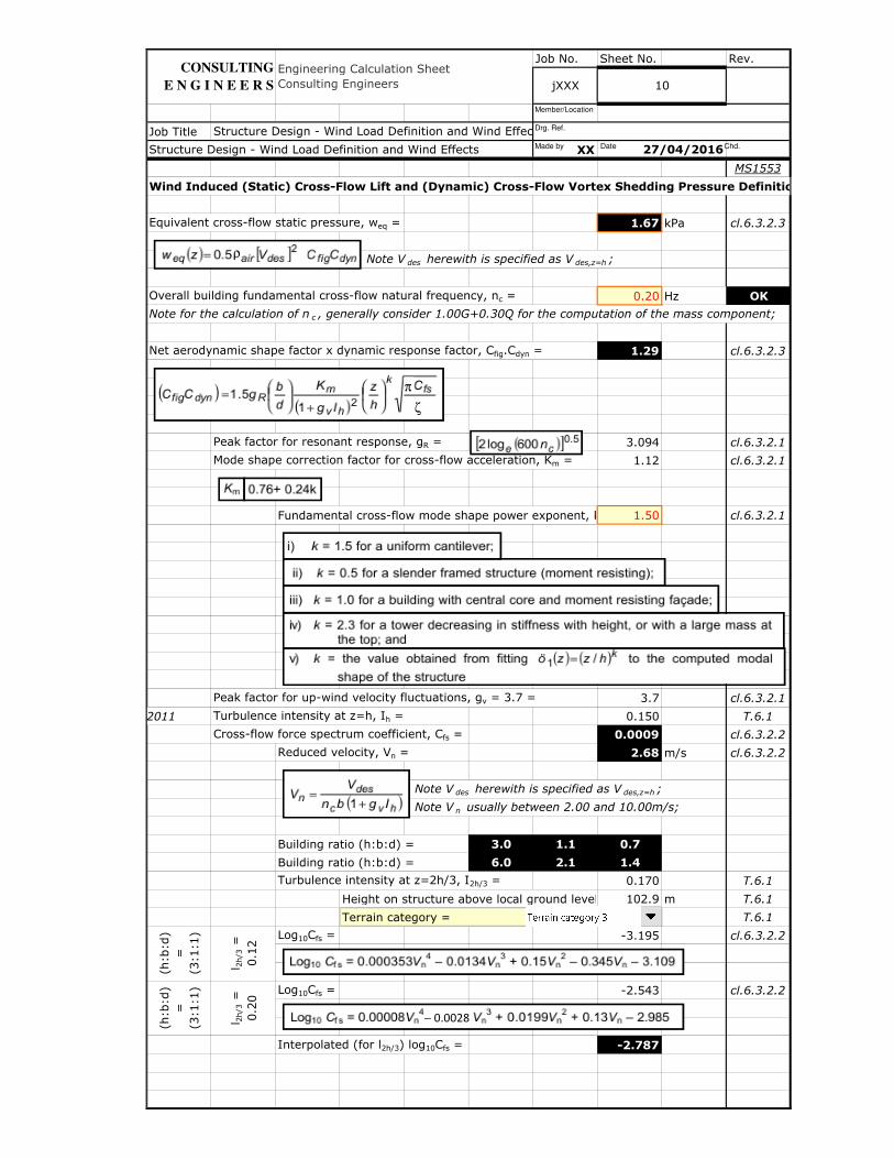
Wind Induced (Static) Cross-Flow Lift and (Dynamic) Cross-Flow Vortex Shedding Pressure Definition
Equivalent cross-flow static pressure, weq = 1.67 kPa cl.6.3.2.3
Note V des herewith is specified as V des,z=h ;
Overall building fundamental cross-flow natural frequency, nc = 0.20 Hz OK
Note for the calculation of n c , generally consider 1.00G+0.30Q for the computation of the mass component;
Net aerodynamic shape factor x dynamic response factor, Cfig.Cdyn = 1.29 cl.6.3.2.3
Peak factor for resonant response, gR = 3.094 cl.6.3.2.1
Mode shape correction factor for cross-flow acceleration, Km = 1.12 cl.6.3.2.1
Fundamental cross-flow mode shape power exponent, k = 1.50 cl.6.3.2.1
Peak factor for up-wind velocity fluctuations, gv = 3.7 = 3.7 cl.6.3.2.1
AS/NZS 1170.2:2011 Turbulence intensity at z=h, Ih = 0.150 T.6.1
Cross-flow force spectrum coefficient, Cfs = 0.0009 cl.6.3.2.2
Reduced velocity, Vn = 2.68 m/s cl.6.3.2.2
Note V des herewith is specified as V des,z=h ;
Note V n usually between 2.00 and 10.00m/s;
Building ratio (h:b:d) = 3.0 1.1 0.7
Building ratio (h:b:d) = 6.0 2.1 1.4
Turbulence intensity at z=2h/3, I2h/3 = 0.170 T.6.1
Height on structure above local ground level, z = 2h/3 =102.9 m T.6.1
Terrain category = T.6.1
Log10Cfs = -3.195 cl.6.3.2.2
Log10Cfs = -2.543 cl.6.3.2.2
Interpolated (for l2h/3) log10Cfs = -2.787
Structure Design - Wind Load Definition and Wind Effects v2015.01.xlsm
Structure Design - Wind Load Definition and Wind Effects 27/04/2016
CONSULTING
E N G I N E E R S
Engineering Calculation Sheet
Consulting Engineers jXXX 10
l 2h/3
=
0.1
2
(h:b
:d)
=
(3:1
:1)
(h:b
:d)
=
(3:1
:1)
l 2h/3
=
0.2
0
Made by Date Chd.
Drg. Ref.
Member/Location
ζ
π
ρ
− 0.0028

Job No. Sheet No. Rev.
Job Title
XX
MS1553
Wind Induced (Static) Cross-Flow Lift and (Dynamic) Cross-Flow Vortex Shedding Pressure Definition
Log10Cfs = -3.228 cl.6.3.2.2
Log10Cfs = -2.599 cl.6.3.2.2
Interpolated (for l2h/3) log10Cfs = -2.835
Log10Cfs = -3.164 cl.6.3.2.2
Log10Cfs = -2.969 cl.6.3.2.2
Interpolated (for l2h/3) log10Cfs = -3.042
Log10Cfs = -3.184 cl.6.3.2.2
Log10Cfs = -2.980 cl.6.3.2.2
Interpolated (for l2h/3) log10Cfs = -3.057
Interpolated (for b) log10Cfs = -3.071
Interpolated (for d) log10Cfs = -2.915
Interpolated (for b and d, weighted) log10Cfs = -3.033
Damping ratio (as a fraction of critical) for ULS, ζULS = 0.020 T.6.2
(h:b
:d)
=
(6:1
:2)
l 2h/3
=
0.2
0
(h:b
:d)
=
(6:1
:1)
l 2h/3
=
0.2
0l 2
h/3
= 0
.12
(h:b
:d)
=
(6:2
:1)
(h:b
:d)
=
(6:2
:1)
l 2h/3
= 0
.20
(h:b
:d)
=
(6:1
:2)
l 2h/3
=
0.1
2
Structure Design - Wind Load Definition and Wind Effects v2015.01.xlsm
Structure Design - Wind Load Definition and Wind Effects 27/04/2016
CONSULTING
E N G I N E E R S
Engineering Calculation Sheet
Consulting Engineers jXXX 11
(h:b
:d)
=
(6:1
:1)
l 2h/3
=
0.1
2
Made by Date Chd.
Drg. Ref.
Member/Location

Job No. Sheet No. Rev.
Job Title
XX
MS1553
Wind Induced (Dynamic) Acceleration Response Criteria for Occupancy Comfort
Note equations within this section are intrinsically linked to the SD - Wind Pressure {1D} sheet;
Peak acceleration criteria adopted =
0.177 m/s2
17.7 mg
1.77 %g
Overall building fundamental along-flow natural frequency, na (0.06 0.20 Hz OK
Period of maximum response, T = 600s = 600 s
Return period, R (0.5 ≤ R ≤ 10) = 10.0 year(s) OK
0.177 m/s2
17.7 mg
1.77 %g
Overall building fundamental cross-flow natural frequency, nc (0.06 0.20 Hz OK
Period of maximum response, T = 600s = 600 s
Return period, R (0.5 ≤ R ≤ 10) = 10.0 year(s) OK
Peak acceleration criteria
Note usually return period of 5 years (residential) and 10 years (office);
Melbourne
Melbourne
Along-flow peak gust acceleration criteria, ẍmax,limit =
Cross-flow vortex shedding acceleration criteria, ÿmax,limit =
Structure Design - Wind Load Definition and Wind Effects 27/04/2016
Structure Design - Wind Load Definition and Wind Effects v2015.01.xlsm
CONSULTING
E N G I N E E R S
Engineering Calculation Sheet
Consulting Engineers jXXX 1
Made by Date Chd.
Drg. Ref.
Member/Location
���� ,"#�#� � 2$% %�& 0.68 � $%'5 ) *+.� *�.,-"../
ÿ�� ,"#�#� � 2$% %1& 0.68 � $%'5 ) *+.� *�.,-"..2

Job No. Sheet No. Rev.
Job Title
XX
MS1553
Wind Induced (Dynamic) Along-Flow Gust Acceleration Response [MS1553]
Note equations within this section are intrinsically linked to the SD - Wind Pressure {1D} sheet;
0.104 m/s2
10.4 mg
1.04 %g
Average mass per unit height, m0 = (1.00G+0.30Q)/h = 690369 kg/m cl.6.2.2
Note generally consider 1.00G+0.30Q for the computation of the mass component;
Total dead load of building, G = 1000 MN
Total live load of building, Q = 150 MN
Total dynamic load of building, 1.00G+0.30Q = 1045 MN
Average roof height of the structure above ground, h = 154.3 m
Average roof height of the structure above ground, h = 154.3 m cl.6.2.1
Density of air, ρair = 1.225kg/m3 = 1.225 kg/m
3 cl.6.2.2
Peak factor for resonant response, gR = 3.094 cl.6.2.1
Size reduction factor, S = 0.086 cl.6.2.1
Spectrum of turbulence in approaching wind stream, Et = 0.082 cl.6.2.1
Damping ratio (as a fraction of critical) for SLS, ζSLS = 0.005 T.6.2
Note ζ SLS usually 0.01 steel buildings and 0.01 concrete buildings; CTBUH
Note ζ SLS usually 0.01 steel buildings and 0.01 concrete buildings; AS/NZS 1170.2:2011
Peak factor for up-wind velocity fluctuations, gv = 3.7 = 3.7 cl.6.2.1
Turbulence intensity at z=h, Ih = 0.150 T.6.1
Base wind bending moment, ΣM = 1170 MNm cl.6.2.2
Dynamic response factor, Cdyn,z=h = 1.08 cl.6.1
Along-flow peak gust acceleration utilisation, ẍmax/ẍmax,limit = 58% OK
Along-flow peak gust acceleration, ẍmax = cl.6.2.2
Structure Design - Wind Load Definition and Wind Effects 27/04/2016
Structure Design - Wind Load Definition and Wind Effects v2015.01.xlsm
CONSULTING
E N G I N E E R S
Engineering Calculation Sheet
Consulting Engineers jXXX 2
Made by Date Chd.
Drg. Ref.
Member/Location
���� � 34��� �')�6%7%8964:6%)%86;<)7=�7�)�)%>?%@A64)%8���� � 34��� �
B�#C@DE� F��G1 � 2@HE� � I9J#K,L#.ML�CMN OMP�QRS ��TR>R�TU�
����
� 34��� �2E� @D�F��G1 � 2@HE� �0.5B�#C I9J#K,L#.ML�CMN OMP�QRS ��TR>R�
TU�
���� � 34��� �2E� @D�F��G1 � 2@HE� � �7�)V?%>�)%>?%@A64)%8, ΣA9MX.,TU�
Job No. Sheet No. Rev.
Job Title
XX
MS1553
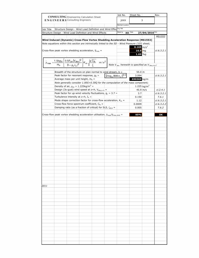
Wind Induced (Dynamic) Cross-Flow Vortex Shedding Acceleration Response [MS1553]
Note equations within this section are intrinsically linked to the SD - Wind Pressure {1D} sheet;
0.169 m/s2
16.9 mg
1.69 %g
Note V des herewith is specified as V des,z=h ;
Breadth of the structure on plan normal to wind stream, b = 55.0 m
Peak factor for resonant response, gR = 3.094 cl.6.3.2.1
Average mass per unit height, m0 = 690369 kg/m
Note generally consider 1.00G+0.30Q for the computation of the mass component;
Density of air, ρair = 1.225kg/m3 = 1.225 kg/m
3
Design (3s-gust) wind speed at z=h, Vdes,z=h = 45.9 m/s cl.2.4.1
Peak factor for up-wind velocity fluctuations, gv = 3.7 = 3.7 cl.6.3.2.1
Turbulence intensity at z=h, Ih = 0.150 T.6.1
Mode shape correction factor for cross-flow acceleration, Km = 1.12 cl.6.3.2.1
Cross-flow force spectrum coefficient, Cfs = 0.0009 cl.6.3.2.2
Damping ratio (as a fraction of critical) for SLS, ζSLS = 0.005 T.6.2
Cross-flow peak vortex shedding acceleration utilisation, ÿmax/ÿmax,limit = 95% OK
AS/NZS 1170.2:2011
Cross-flow peak vortex shedding acceleration, ÿmax = cl.6.3.2.1
Structure Design - Wind Load Definition and Wind Effects 27/04/2016
Structure Design - Wind Load Definition and Wind Effects v2015.01.xlsm
jXXX 3
Engineering Calculation Sheet
Consulting Engineers
CONSULTING
E N G I N E E R S
Made by Date Chd.
Drg. Ref.
Member/Location
ρ π
ζ

Job No. Sheet No. Rev.
Job Title
XX
CTBUH
Wind Induced (Dynamic) Along-Flow Gust Acceleration Response [CTBUH]
Note equations within this section are intrinsically linked to the SD - Wind Pressure {1D} sheet;
0.063 m/s2
6.3 mg
0.63 %g
Gust factor for resonant component, Gres = 1.107
Peak factor, gR = 3.094
Longitudinal turbulence intensity at height h, (σν/V)h = I 0.150
Size factor, S = 0.086
Overall building fundamental along-flow natural frequency, n0.20 Hz
Average roof height of the structure above ground, h154.3 m
Design (mean hourly) wind speed at z=h, Vh 29.5 m/s
Design (3s-gust) wind speed at z=h, V 45.9 m/s
Peak factor for up-wind velocity fluctuations, g3.7
Breadth of the structure on plan normal to wind stream, b =55.0 m
Longitudinal turbulence spectrum, Et = 0.082
Reduced frequency, N = naLh/Vh = 13.4
Effective turbulence length scale at h, Lh = 1000(h/10)1981.9 m
Damping ratio (as a fraction of critical) for SLS, ζSLS = 0.005
Mean base overturning moment, M = 0.6(0.5ρair).Vh2.b.h
2 = 420 MNm
Density of air, ρair = 1.225kg/m3 = 1.225 kg/m
3
Inertial base bending moment, M1 = (1/3).ρS.b.d.h2.(2π.na)
2 = 11598 MNm
Note the inertial base bending moment, M 1 is calculated for unit displacement
at the top of the building for a constant density and a linear mode shape;
Building density, ρS = m0/AF = 481 kg/m3
Average mass per unit height, m0 = 690369 kg/m
Floor area, AF = 1436 m2
Depth of the structure on plan parallel to wind stream, d = 35.0 m
Along-flow peak gust acceleration utilisation, ẍmax/ẍmax,limit = 36% OK
Along-flow peak gust acceleration, ẍmax =
Structure Design - Wind Load Definition and Wind Effects 27/04/2016
Structure Design - Wind Load Definition and Wind Effects v2015.01.xlsm
jXXX 4
CONSULTING
E N G I N E E R S
Engineering Calculation Sheet
Consulting Engineers
Made by Date Chd.
Drg. Ref.
Member/Location
���� � YCP� AA- 2�%� �
YCP� � @D2 Z[/O � F��/G\]\
F � 11 � 3.5%��O� 1 � 4%��O�
�� � 0.47�2 � �� /�
O� � OMP�,TU�1 � @HE�

Job No. Sheet No. Rev.
Job Title
XX
CTBUH
Wind Induced (Dynamic) Cross-Flow Vortex Shedding Acceleration Response [CTBUH]
Note equations within this section are intrinsically linked to the SD - Wind Pressure {1D} sheet;
0.124 m/s2
12.4 mg
1.24 %g
Peak factor, gR = 3.094
Density of air, ρair = 1.225kg/m3 = 1.225 kg/m
3
Design (mean hourly) wind speed at z=h, Vh = 29.5 m/s
Building density, ρS = 481 kg/m3
Depth of the structure on plan parallel to wind stream, d = 35.0 m
Cross-flow force spectrum coefficient, CFS = 0.0009
Reduced velocity, Vn = Vh/(nc.b) = 2.68 m/s
Overall building fundamental cross-flow natural frequency, n0.20 Hz
Breadth of the structure on plan normal to wind stream, b =55.0 m
Damping ratio (as a fraction of critical) for SLS, ζSLS = 0.005
Mode shape correction factor for cross-flow acceleration, Km = 1.12
Cross-flow peak vortex shedding acceleration utilisation, ÿmax/ÿmax,limit = 70% OK
Cross-flow peak vortex shedding acceleration, ÿmax =
Structure Design - Wind Load Definition and Wind Effects 27/04/2016
Structure Design - Wind Load Definition and Wind Effects v2015.01.xlsm
jXXX 5
CONSULTING
E N G I N E E R S
Engineering Calculation Sheet
Consulting Engineers
Made by Date Chd.
Drg. Ref.
Member/Location
�̂�� � 34@DB�#CO��B\> �9_\G . `�

Job No. Sheet No. Rev. Job No. Sheet No. Rev. Job No. Sheet No. Rev.
Job Title Job Title Job Title
XX XX XX
MS1553 MS1553 MS1553
Wind Load in Direction X Wind Load in Direction Y
Note combo boxes and their corresponding cells within this section are intrinsically linked to the SD - Wind Pressure {1D} and SD - Wind Accelerations {1D} sheets; Note combo boxes and their corresponding cells within this section are intrinsically linked to the SD - Wind Pressure {1D} and SD - Wind Accelerations {1D} sheets;
Design (3s-gust) wind speed at z=h, Vdes,z=h = 45.9 m/s cl.2.4.1 P-∆ factor in direction X = 1.33 Design (3s-gust) wind speed at z=h, Vdes,z=h = 45.9 m/s cl.2.4.1
Height from the ground to the top of the structure, ht = 154.3 m OK P-∆ wind shear in X (factored by 1.4) as a % of total building DL, G = 1.7% Height from the ground to the top of the structure, ht = 154.3 m OK
Average roof height of the structure above ground, h = 154.3 m Peak acceleration criteria adopted = Average roof height of the structure above ground, h = 154.3 m
Breadth of the structure on plan normal to wind stream, b = 35.0 m Total DL and LL of building, G and Q = 1000 150 MN Breadth of the structure on plan normal to wind stream, b = 55.0 m
Depth of the structure on plan parallel to wind stream, d = 55.0 m Building / floor area, AB / AF = 64621 1436 m2
17.8 Depth of the structure on plan parallel to wind stream, d = 35.0 m
Height on structure above local ground level, z = 154.3 m Damping ratio (as a fraction of critical) for SLS, ζSLS = 0.005 kPa Height on structure above local ground level, z = 154.3 m
Station (3s-gust) wind speed, VS = 33.5 m/s T.3.1 Base wind bending moment, ΣM = 715 MNm cl.6.2.2 Station (3s-gust) wind speed, VS = 33.5 m/s T.3.1
Terrain category = T.4.1 CTBUH Cross-flow force spectrum coefficient, CFS = 0.0020 Terrain category = T.4.1
Importance factor, I = 1.00 T.3.2 Along-flow peak gust acceleration = 6.9 mg Importance factor, I = 1.00 T.3.2
Overall building fundamental along-flow natural frequency, na = 0.20 Hz OK Along-flow peak gust acceleration utilisation = 39% OK Overall building fundamental along-flow natural frequency, na = 0.20 Hz OK
Damping ratio (as a fraction of critical) for ULS, ζULS = 0.020 T.6.2 Cross-flow peak vortex shedding acceleration = 15.8 mg Damping ratio (as a fraction of critical) for ULS, ζULS = 0.020 T.6.2
Overall building fundamental cross-flow natural frequency, nc = 0.20 Hz OK Cross-flow peak vortex shedding acceleration utilisation = 89% OK Overall building fundamental cross-flow natural frequency, nc = 0.20 Hz OK
Fundamental cross-flow mode shape power exponent, k = 1.50 cl.6.3.2.1 Fundamental cross-flow mode shape power exponent, k = 1.50 cl.6.3.2.1
1.74 1.00 0.29 1.45 1.81 1.67
Along Along Along Cross Cross Cross ΣΣΣΣ Along Along Along Along Along Along Along Along Cross Cross Cross
Storey Height Breadth Flow Flow Flow Flow Flow Flow Building Flow Net Flow Net Flow Flow Flow Storey Height Breadth Flow Flow Flow Flow Flow Flow
Storey Height Tributary Tributary Pressure Force P∆∆∆∆ Force Pressure Force P∆∆∆∆ Force Height Windward Leeward ΣΣΣΣMoment P∆∆∆∆ Base P∆∆∆∆ Base Storey Height Tributary Tributary Pressure Force P∆∆∆∆ Force Pressure Force P∆∆∆∆ Force
hs in X in X in X in Y in Y in Y ΣΣΣΣhs Pressure Pressure in X Shear X Moment X hs in Y in Y in Y in X in X in X
m m m kPa kN kN kPa kN kN m in X kPa in X kPa MNm kN MNm m m m kPa kN kN kPa kN kN
45 154.3 12347 6397 ΣΣΣΣ 715 952 45 154.3 20207 6811
St01 2.250 35.0 1.69 133 177 0.19 24 32 Stump 1.000 0.28 1.45 328 12347 435 St01 2.250 55.0 1.76 218 290 0.32 25 34
St02 4.500 3.750 35.0 1.69 222 296 0.19 39 53 5.500 0.28 1.45 286 12169 381 St02 4.500 3.750 55.0 1.76 364 484 0.32 42 56
St03 3.000 3.000 35.0 1.69 178 236 0.19 32 42 8.500 0.28 1.45 259 11874 345 St03 3.000 3.000 55.0 1.76 291 387 0.32 34 45
St04 3.000 3.000 35.0 1.69 178 236 0.19 32 42 11.500 0.28 1.45 233 11637 310 St04 3.000 3.000 55.0 1.76 291 387 0.32 34 45
St05 3.000 3.000 35.0 1.69 178 236 0.19 32 42 14.500 0.28 1.45 207 11401 276 St05 3.000 3.000 55.0 1.76 291 387 0.32 34 45
St06 3.000 3.000 35.0 1.69 178 236 0.19 32 42 17.500 0.28 1.45 182 11164 242 St06 3.000 3.000 55.0 1.76 291 387 0.32 34 45
St07 3.000 3.000 35.0 1.69 178 236 0.19 32 42 20.500 0.28 1.45 157 Storey 10928 210 St07 3.000 3.000 55.0 1.76 291 387 0.32 34 45
St08 3.000 3.000 35.0 1.69 178 236 0.19 32 42 23.500 0.28 1.45 133 10691 178 St08 3.000 3.000 55.0 1.76 291 387 0.32 34 45
St09 3.000 3.750 35.0 1.69 222 296 0.19 39 53 26.500 0.28 1.45 110 Note that a transfer 10455 146 St09 3.000 3.750 55.0 1.76 364 484 0.32 42 56
St10 4.500 4.500 35.0 1.69 267 355 0.19 47 63 31.000 0.28 1.45 75 level is akin to a 10159 100 St10 4.500 4.500 55.0 1.76 436 581 0.32 50 67
St11 4.500 5.250 35.0 1.69 311 414 0.19 55 74 35.500 0.28 1.45 42 100% effective 9805 56 St11 4.500 5.250 55.0 1.76 509 677 0.32 59 78
St12 6.000 4.650 35.0 1.69 276 367 0.19 49 65 41.500 0.28 1.45 387 outrigger for base 9391 516 St12 6.000 4.650 55.0 1.76 451 600 0.32 52 69
St13 3.300 3.300 35.0 1.69 196 260 0.19 35 46 44.800 0.28 1.45 365 moment resolution; 9024 487 St13 3.300 3.300 55.0 1.76 320 426 0.32 37 49
St14 3.300 3.300 35.0 1.69 196 260 0.19 35 46 48.100 0.28 1.45 343 For no transfer level 8764 458 St14 3.300 3.300 55.0 1.76 320 426 0.32 37 49
St15 3.300 3.300 35.0 1.69 196 260 0.19 35 46 51.400 0.28 1.45 322 insert St01; 8504 430 St15 3.300 3.300 55.0 1.76 320 426 0.32 37 49
St16 3.300 3.300 35.0 1.76 203 271 0.54 97 129 54.700 0.29 1.45 302 8244 402 St16 3.300 3.300 55.0 1.83 333 443 0.90 104 138
St17 3.300 3.300 35.0 1.76 203 271 0.54 97 129 58.000 0.29 1.45 282 7973 376 St17 3.300 3.300 55.0 1.83 333 443 0.90 104 138
St18 3.300 3.300 35.0 1.76 203 271 0.54 97 129 61.300 0.29 1.45 263 7703 351 St18 3.300 3.300 55.0 1.83 333 443 0.90 104 138
St19 3.300 3.300 35.0 1.76 203 271 0.54 97 129 64.600 0.29 1.45 245 7432 326 St19 3.300 3.300 55.0 1.83 333 443 0.90 104 138
St20 3.300 3.300 35.0 1.76 203 271 0.54 97 129 67.900 0.29 1.45 227 7162 303 St20 3.300 3.300 55.0 1.83 333 443 0.90 104 138
St21 3.300 3.300 35.0 1.76 203 271 0.54 97 129 71.200 0.29 1.45 210 6891 280 St21 3.300 3.300 55.0 1.83 333 443 0.90 104 138
St22 3.300 3.900 35.0 1.76 240 320 0.54 115 153 74.500 0.29 1.45 194 6621 258 St22 3.300 3.900 55.0 1.83 393 523 0.90 122 163
St23 4.500 3.900 35.0 1.76 240 320 0.54 115 153 79.000 0.29 1.45 172 6301 230 St23 4.500 3.900 55.0 1.83 393 523 0.90 122 163
St24 3.300 3.300 35.0 1.76 203 271 0.54 97 129 82.300 0.29 1.45 158 5981 210 St24 3.300 3.300 55.0 1.83 333 443 0.90 104 138
St25 3.300 3.300 35.0 1.76 203 271 0.54 97 129 85.600 0.29 1.45 143 5711 191 St25 3.300 3.300 55.0 1.83 333 443 0.90 104 138
St26 3.300 3.300 35.0 1.76 203 271 0.54 97 129 88.900 0.29 1.45 130 5440 173 St26 3.300 3.300 55.0 1.83 333 443 0.90 104 138
St27 3.300 3.300 35.0 1.76 203 271 0.54 97 129 92.200 0.29 1.45 117 5170 156 St27 3.300 3.300 55.0 1.83 333 443 0.90 104 138
St28 3.300 3.300 35.0 1.76 203 271 0.54 97 129 95.500 0.29 1.45 105 4899 140 St28 3.300 3.300 55.0 1.83 333 443 0.90 104 138
St29 3.300 3.300 35.0 1.76 203 271 0.54 97 129 98.800 0.29 1.45 94 4629 125 St29 3.300 3.300 55.0 1.83 333 443 0.90 104 138
St30 3.300 3.300 35.0 1.76 203 271 0.54 97 129 102.100 0.29 1.45 83 4358 110 St30 3.300 3.300 55.0 1.83 333 443 0.90 104 138
St31 3.300 3.300 35.0 1.74 201 267 1.00 181 240 105.400 0.29 1.45 73 4087 97 St31 3.300 3.300 55.0 1.81 328 437 1.67 192 256
St32 3.300 3.300 35.0 1.74 201 267 1.00 181 240 108.700 0.29 1.45 63 3821 84 St32 3.300 3.300 55.0 1.81 328 437 1.67 192 256
St33 3.300 3.300 35.0 1.74 201 267 1.00 181 240 112.000 0.29 1.45 54 3554 72 St33 3.300 3.300 55.0 1.81 328 437 1.67 192 256
St34 3.300 3.300 35.0 1.74 201 267 1.00 181 240 115.300 0.29 1.45 46 3287 61 St34 3.300 3.300 55.0 1.81 328 437 1.67 192 256
St35 3.300 3.300 35.0 1.74 201 267 1.00 181 240 118.600 0.29 1.45 39 3020 52 St35 3.300 3.300 55.0 1.81 328 437 1.67 192 256
St36 3.300 3.300 35.0 1.74 201 267 1.00 181 240 121.900 0.29 1.45 32 2753 42 St36 3.300 3.300 55.0 1.81 328 437 1.67 192 256
St37 3.300 3.300 35.0 1.74 201 267 1.00 181 240 125.200 0.29 1.45 26 2486 34 St37 3.300 3.300 55.0 1.81 328 437 1.67 192 256
St38 3.300 3.300 35.0 1.74 201 267 1.00 181 240 128.500 0.29 1.45 20 2220 27 St38 3.300 3.300 55.0 1.81 328 437 1.67 192 256
St39 3.300 3.300 35.0 1.74 201 267 1.00 181 240 131.800 0.29 1.45 15 1953 20 St39 3.300 3.300 55.0 1.81 328 437 1.67 192 256
St40 3.300 3.300 35.0 1.74 201 267 1.00 181 240 135.100 0.29 1.45 11 1686 15 St40 3.300 3.300 55.0 1.81 328 437 1.67 192 256
St41 3.300 3.300 35.0 1.74 201 267 1.00 181 240 138.400 0.29 1.45 8 1419 10 St41 3.300 3.300 55.0 1.81 328 437 1.67 192 256
St42 3.300 3.300 35.0 1.74 201 267 1.00 181 240 141.700 0.29 1.45 5 1152 6 St42 3.300 3.300 55.0 1.81 328 437 1.67 192 256
St43 3.300 3.300 35.0 1.74 201 267 1.00 181 240 145.000 0.29 1.45 3 885 3 St43 3.300 3.300 55.0 1.81 328 437 1.67 192 256
Transfer Level
cf. 0.002
MS1553
Automated
Calculations
CONSULTING
E N G I N E E R S
Engineering Calculation Sheet
Consulting Engineers
CONSULTING
E N G I N E E R S
Engineering Calculation Sheet
Consulting Engineers
CONSULTING
E N G I N E E R SjXXX 1 jXXX 2
27/04/2016 Structure Design - Wind Load Definition and Wind Effects
Engineering Calculation Sheet
Consulting Engineers jXXX 3
27/04/2016Structure Design - Wind Load Definition and Wind Effects
Structure Design - Wind Load Definition and Wind Effects v2015.01.xlsm Structure Design - Wind Load Definition and Wind Effects v2015.01.xlsm Structure Design - Wind Load Definition and Wind Effects v2015.01.xlsm
27/04/2016 Structure Design - Wind Load Definition and Wind Effects
Wind Load
Generation and Wind Acceleration in X
Made by Date Chd.
Drg. Ref.
Member/Location
Made by Date Chd.
Drg. Ref.
Member/Location
Made by Date Chd.
Drg. Ref.
Member/Location
Wind Pressure Analysis in X
Storey Tabulation in
X and Y
Wind Pressure Analysis in Y
Job No. Sheet No. Rev. Job No. Sheet No. Rev. Job No. Sheet No. Rev.
Job Title Job Title Job Title
XX XX XX
MS1553 MS1553 MS1553
Wind Load in Direction X Wind Load in Direction Y
Note combo boxes and their corresponding cells within this section are intrinsically linked to the SD - Wind Pressure {1D} and SD - Wind Accelerations {1D} sheets; Note combo boxes and their corresponding cells within this section are intrinsically linked to the SD - Wind Pressure {1D} and SD - Wind Accelerations {1D} sheets;
Design (3s-gust) wind speed at z=h, Vdes,z=h = 45.9 m/s cl.2.4.1 P-∆ factor in direction X = 1.33 Design (3s-gust) wind speed at z=h, Vdes,z=h = 45.9 m/s cl.2.4.1
Height from the ground to the top of the structure, ht = 154.3 m OK P-∆ wind shear in X (factored by 1.4) as a % of total building DL, G = 1.7% Height from the ground to the top of the structure, ht = 154.3 m OK
Average roof height of the structure above ground, h = 154.3 m Peak acceleration criteria adopted = Average roof height of the structure above ground, h = 154.3 m
Breadth of the structure on plan normal to wind stream, b = 35.0 m Total DL and LL of building, G and Q = 1000 150 MN Breadth of the structure on plan normal to wind stream, b = 55.0 m
Depth of the structure on plan parallel to wind stream, d = 55.0 m Building / floor area, AB / AF = 64621 1436 m2
17.8 Depth of the structure on plan parallel to wind stream, d = 35.0 m
Height on structure above local ground level, z = 154.3 m Damping ratio (as a fraction of critical) for SLS, ζSLS = 0.005 kPa Height on structure above local ground level, z = 154.3 m
Station (3s-gust) wind speed, VS = 33.5 m/s T.3.1 Base wind bending moment, ΣM = 715 MNm cl.6.2.2 Station (3s-gust) wind speed, VS = 33.5 m/s T.3.1
Terrain category = T.4.1 CTBUH Cross-flow force spectrum coefficient, CFS = 0.0020 Terrain category = T.4.1
Importance factor, I = 1.00 T.3.2 Along-flow peak gust acceleration = 6.9 mg Importance factor, I = 1.00 T.3.2
Overall building fundamental along-flow natural frequency, na = 0.20 Hz OK Along-flow peak gust acceleration utilisation = 39% OK Overall building fundamental along-flow natural frequency, na = 0.20 Hz OK
Damping ratio (as a fraction of critical) for ULS, ζULS = 0.020 T.6.2 Cross-flow peak vortex shedding acceleration = 15.8 mg Damping ratio (as a fraction of critical) for ULS, ζULS = 0.020 T.6.2
Overall building fundamental cross-flow natural frequency, nc = 0.20 Hz OK Cross-flow peak vortex shedding acceleration utilisation = 89% OK Overall building fundamental cross-flow natural frequency, nc = 0.20 Hz OK
Fundamental cross-flow mode shape power exponent, k = 1.50 cl.6.3.2.1 Fundamental cross-flow mode shape power exponent, k = 1.50 cl.6.3.2.1
1.74 1.00 0.29 1.45 1.81 1.67
Along Along Along Cross Cross Cross ΣΣΣΣ Along Along Along Along Along Along Along Along Cross Cross Cross
Storey Height Breadth Flow Flow Flow Flow Flow Flow Building Flow Net Flow Net Flow Flow Flow Storey Height Breadth Flow Flow Flow Flow Flow Flow
Storey Height Tributary Tributary Pressure Force P∆∆∆∆ Force Pressure Force P∆∆∆∆ Force Height Windward Leeward ΣΣΣΣMoment P∆∆∆∆ Base P∆∆∆∆ Base Storey Height Tributary Tributary Pressure Force P∆∆∆∆ Force Pressure Force P∆∆∆∆ Force
hs in X in X in X in Y in Y in Y ΣΣΣΣhs Pressure Pressure in X Shear X Moment X hs in Y in Y in Y in X in X in X
m m m kPa kN kN kPa kN kN m in X kPa in X kPa MNm kN MNm m m m kPa kN kN kPa kN kN
45 154.3 12347 6397 ΣΣΣΣ 715 952 45 154.3 20207 6811
cf. 0.002
MS1553
Automated
Calculations
CONSULTING
E N G I N E E R S
Engineering Calculation Sheet
Consulting Engineers
CONSULTING
E N G I N E E R S
Engineering Calculation Sheet
Consulting Engineers
CONSULTING
E N G I N E E R SjXXX 1 jXXX 2
27/04/2016 Structure Design - Wind Load Definition and Wind Effects
Engineering Calculation Sheet
Consulting Engineers jXXX 3
27/04/2016Structure Design - Wind Load Definition and Wind Effects
Structure Design - Wind Load Definition and Wind Effects v2015.01.xlsm Structure Design - Wind Load Definition and Wind Effects v2015.01.xlsm Structure Design - Wind Load Definition and Wind Effects v2015.01.xlsm
27/04/2016 Structure Design - Wind Load Definition and Wind Effects
Wind Load
Generation and Wind Acceleration in X
Made by Date Chd.
Drg. Ref.
Member/Location
Made by Date Chd.
Drg. Ref.
Member/Location
Made by Date Chd.
Drg. Ref.
Member/Location
Wind Pressure Analysis in X
Storey Tabulation in
X and Y
Wind Pressure Analysis in Y
St44 3.300 4.650 35.0 1.74 283 376 1.00 255 339 148.300 0.29 1.45 1 619 1 St44 3.300 4.650 55.0 1.81 463 615 1.67 271 361
St45 6.000 3.000 35.0 1.74 182 243 1.00 164 218 154.300 0.29 1.45 0 243 0 St45 6.000 3.000 55.0 1.81 299 397 1.67 175 233
Note when expanding or contracting table, refresh equations within columns with summation, Σ as they are dependent upon other rows; Note when expanding or contracting table, refresh equations within columns with summation, Σ as they are dependent upon other rows;

Job No. Sheet No. Rev. Job No. Sheet No. Rev. Job No. Sheet No. Rev.
Job Title Job Title Job Title
XX XX XX
MS1553 MS1553 MS1553
Wind Load Shear Force Diagrams in Direction X and Y Wind Load Bending Moment Diagrams in Direction X and Y
Note combo boxes and their corresponding cells within this section are intrinsically linked to the SD - Wind Pressure {1D} and SD - Wind Accelerations {1D} sheets;
P-∆ factor in direction Y = 1.33
P-∆ wind shear in Y (factored by 1.4) as a % of total building DL, G = 2.8%
Peak acceleration criteria adopted =
Total DL and LL of building, G and Q = 1000 150 MN
Building / floor area, AB / AF = 64621 1436 m2
17.8
Damping ratio (as a fraction of critical) for SLS, ζSLS = 0.005 kPa
Base wind bending moment, ΣM = 1170 MNm cl.6.2.2
CTBUH Cross-flow force spectrum coefficient, CFS = 0.0009
Along-flow peak gust acceleration = 10.4 mg
Along-flow peak gust acceleration utilisation = 58% OK
Cross-flow peak vortex shedding acceleration = 16.9 mg
Cross-flow peak vortex shedding acceleration utilisation = 95% OK
0.28 1.53
ΣΣΣΣ Along Along Along Along Along
Building Flow Net Flow Net Flow Flow Flow
Height Windward Leeward ΣΣΣΣMoment P∆∆∆∆ Base P∆∆∆∆ Base
ΣΣΣΣhs Pressure Pressure in Y Shear Y Moment Y
m in Y kPa in Y kPa MNm kN MNm
ΣΣΣΣ 1170 1558
Stump 1.000 0.27 1.53 536 20207 713
5.500 0.27 1.53 469 19917 623
8.500 0.27 1.53 425 19433 565
11.500 0.27 1.53 382 19046 508
14.500 0.27 1.53 339 18659 452
17.500 0.27 1.53 298 18272 397
20.500 0.27 1.53 258 Storey 17885 343
23.500 0.27 1.53 218 17498 291
26.500 0.27 1.53 180 Note that a transfer 17111 239
31.000 0.27 1.53 123 level is akin to a 16627 164
35.500 0.27 1.53 69 100% effective 16047 92
41.500 0.27 1.53 633 outrigger for base 15369 845
44.800 0.27 1.53 597 moment resolution; 14770 796
48.100 0.27 1.53 561 For no transfer level 14344 749
51.400 0.27 1.53 527 insert St01; 13918 703
54.700 0.28 1.53 494 13492 659
58.000 0.28 1.53 462 13050 616
61.300 0.28 1.53 430 12607 574
64.600 0.28 1.53 400 12164 534
67.900 0.28 1.53 372 11721 495
71.200 0.28 1.53 344 11278 458
74.500 0.28 1.53 317 10836 422
79.000 0.28 1.53 282 10312 376
82.300 0.28 1.53 258 9789 343
85.600 0.28 1.53 235 9346 313
88.900 0.28 1.53 213 8904 283
92.200 0.28 1.53 192 8461 255
95.500 0.28 1.53 172 8018 229
98.800 0.28 1.53 153 7575 204
102.100 0.28 1.53 136 7132 180
105.400 0.28 1.53 119 6690 158
108.700 0.28 1.53 103 6253 138
112.000 0.28 1.53 89 5816 118
115.300 0.28 1.53 76 5380 101
118.600 0.28 1.53 63 4943 84
121.900 0.28 1.53 52 4506 69
125.200 0.28 1.53 42 4069 56
128.500 0.28 1.53 33 3633 44
131.800 0.28 1.53 25 3196 33
135.100 0.28 1.53 18 2759 24
138.400 0.28 1.53 13 2323 17
141.700 0.28 1.53 8 1886 11
145.000 0.28 1.53 4 1449 6
Structure Design - Wind Load Definition and Wind Effects v2015.01.xlsm
Structure Design - Wind Load Definition and Wind Effects 27/04/2016
CONSULTING
E N G I N E E R S
Engineering Calculation Sheet
Consulting Engineers jXXX 6
Transfer Level
cf. 0.0009
MS1553
Automated
Calculations
jXXX
CONSULTING
E N G I N E E R S
Structure Design - Wind Load Definition and Wind Effects 27/04/2016
4
Engineering Calculation Sheet
Consulting Engineers 5
CONSULTING
E N G I N E E R S
Engineering Calculation Sheet
Consulting Engineers jXXX
27/04/2016 Structure Design - Wind Load Definition and Wind Effects
Structure Design - Wind Load Definition and Wind Effects v2015.01.xlsmStructure Design - Wind Load Definition and Wind Effects v2015.01.xlsm
Wind Load
Generation and Wind Acceleration in Y
Made by Date Chd.
Drg. Ref.
Member/Location
Made by Date Chd.
Drg. Ref.
Member/Location
Storey Tabulation in
X and Y
Made by Date Chd.
Drg. Ref.
Member/Location
0.000
20.000
40.000
60.000
80.000
100.000
120.000
140.000
160.000
180.000
0 5000 10000 15000 20000 25000
Bu
ild
ing
Heig
ht
(m
)
Shear Force (kN)
Wind Load Shear Force Diagrams
VSLS,X
VSLS,Y
0.000
20.000
40.000
60.000
80.000
100.000
120.000
140.000
160.000
180.000
0 200 400 600 800 1000 1200 1400 1600 1800
Bu
ild
ing
Heig
ht
(m
)
Bending Moment (MNm)
Wind Load Bending Moment Diagrams
MSLS,X
SUM-MSLS,X
MSLS,Y
SUM-MSLS,Y

Job No. Sheet No. Rev. Job No. Sheet No. Rev. Job No. Sheet No. Rev.
Job Title Job Title Job Title
XX XX XX
MS1553 MS1553 MS1553
Wind Load Shear Force Diagrams in Direction X and Y Wind Load Bending Moment Diagrams in Direction X and Y
Note combo boxes and their corresponding cells within this section are intrinsically linked to the SD - Wind Pressure {1D} and SD - Wind Accelerations {1D} sheets;
P-∆ factor in direction Y = 1.33
P-∆ wind shear in Y (factored by 1.4) as a % of total building DL, G = 2.8%
Peak acceleration criteria adopted =
Total DL and LL of building, G and Q = 1000 150 MN
Building / floor area, AB / AF = 64621 1436 m2
17.8
Damping ratio (as a fraction of critical) for SLS, ζSLS = 0.005 kPa
Base wind bending moment, ΣM = 1170 MNm cl.6.2.2
CTBUH Cross-flow force spectrum coefficient, CFS = 0.0009
Along-flow peak gust acceleration = 10.4 mg
Along-flow peak gust acceleration utilisation = 58% OK
Cross-flow peak vortex shedding acceleration = 16.9 mg
Cross-flow peak vortex shedding acceleration utilisation = 95% OK
0.28 1.53
ΣΣΣΣ Along Along Along Along Along
Building Flow Net Flow Net Flow Flow Flow
Height Windward Leeward ΣΣΣΣMoment P∆∆∆∆ Base P∆∆∆∆ Base
ΣΣΣΣhs Pressure Pressure in Y Shear Y Moment Y
m in Y kPa in Y kPa MNm kN MNm
ΣΣΣΣ 1170 1558
Structure Design - Wind Load Definition and Wind Effects v2015.01.xlsm
Structure Design - Wind Load Definition and Wind Effects 27/04/2016
CONSULTING
E N G I N E E R S
Engineering Calculation Sheet
Consulting Engineers jXXX 6
cf. 0.0009
MS1553
Automated
Calculations
jXXX
CONSULTING
E N G I N E E R S
Structure Design - Wind Load Definition and Wind Effects 27/04/2016
4
Engineering Calculation Sheet
Consulting Engineers 5
CONSULTING
E N G I N E E R S
Engineering Calculation Sheet
Consulting Engineers jXXX
27/04/2016 Structure Design - Wind Load Definition and Wind Effects
Structure Design - Wind Load Definition and Wind Effects v2015.01.xlsmStructure Design - Wind Load Definition and Wind Effects v2015.01.xlsm
Wind Load
Generation and Wind Acceleration in Y
Made by Date Chd.
Drg. Ref.
Member/Location
Made by Date Chd.
Drg. Ref.
Member/Location
Storey Tabulation in
X and Y
Made by Date Chd.
Drg. Ref.
Member/Location
100.000
120.000
140.000
160.000
180.000
Bu
ild
ing
Heig
ht
(m
)
Wind Load Shear Force Diagrams
VSLS,X
VSLS,Y
100.000
120.000
140.000
160.000
180.000
Bu
ild
ing
Heig
ht
(m
)
Wind Load Bending Moment Diagrams
MSLS,X
SUM-MSLS,X
MSLS,Y
SUM-MSLS,Y
148.300 0.28 1.53 2 1012 2
154.300 0.28 1.53 0 397 0
as they are dependent upon other rows;

Job No. Sheet No. Rev.
Job Title
XX
MS1553
Wind Load Displacements in Direction X
Note storey references and cumulative building heights within this section are intrinsically linked to the SD - Wind Load {X, Y} sheet;
Criteria for δX / h 1 : 500 =
Criteria for |∆δX| / hs 1 : 500 =
Total Total Total Total Relative Inter Relative Relative
Storey Disp Building Disp Disp Disp Storey Disp Disp
in X, δδδδX Height, h Ratio Ratio in X, ∆δ∆δ∆δ∆δX Height, hs Ratio Ratio
mm m δδδδX / h Check mm m |∆δ∆δ∆δ∆δX| / hs Check
St01 0.00 1.000 0.00000 OK 1.000 0.00000 OK
St02 0.00 5.500 0.00000 OK 4.500 0.00000 OK
St03 0.00 8.500 0.00000 OK 3.000 0.00000 OK
St04 0.00 11.500 0.00000 OK 3.000 0.00000 OK
St05 0.00 14.500 0.00000 OK 3.000 0.00000 OK
St06 0.00 17.500 0.00000 OK 3.000 0.00000 OK
St07 0.00 20.500 0.00000 OK 3.000 0.00000 OK
St08 0.00 23.500 0.00000 OK 3.000 0.00000 OK
St09 0.00 26.500 0.00000 OK 3.000 0.00000 OK
St10 0.00 31.000 0.00000 OK 4.500 0.00000 OK
St11 0.00 35.500 0.00000 OK 4.500 0.00000 OK
St12 0.00 41.500 0.00000 OK 6.000 0.00000 OK
St13 0.00 44.800 0.00000 OK 3.300 0.00000 OK
St14 0.00 48.100 0.00000 OK 3.300 0.00000 OK
St15 0.00 51.400 0.00000 OK 3.300 0.00000 OK
St16 0.00 54.700 0.00000 OK 3.300 0.00000 OK
St17 0.00 58.000 0.00000 OK 3.300 0.00000 OK
St18 0.00 61.300 0.00000 OK 3.300 0.00000 OK
St19 0.00 64.600 0.00000 OK 3.300 0.00000 OK
St20 0.00 67.900 0.00000 OK 3.300 0.00000 OK
St21 0.00 71.200 0.00000 OK 3.300 0.00000 OK
St22 0.00 74.500 0.00000 OK 3.300 0.00000 OK
St23 0.00 79.000 0.00000 OK 4.500 0.00000 OK
St24 0.00 82.300 0.00000 OK 3.300 0.00000 OK
St25 0.00 85.600 0.00000 OK 3.300 0.00000 OK
St26 0.00 88.900 0.00000 OK 3.300 0.00000 OK
St27 0.00 92.200 0.00000 OK 3.300 0.00000 OK
St28 0.00 95.500 0.00000 OK 3.300 0.00000 OK
St29 0.00 98.800 0.00000 OK 3.300 0.00000 OK
St30 0.00 102.100 0.00000 OK 3.300 0.00000 OK
St31 0.00 105.400 0.00000 OK 3.300 0.00000 OK
St32 0.00 108.700 0.00000 OK 3.300 0.00000 OK
St33 0.00 112.000 0.00000 OK 3.300 0.00000 OK
St34 0.00 115.300 0.00000 OK 3.300 0.00000 OK
St35 0.00 118.600 0.00000 OK 3.300 0.00000 OK
St36 0.00 121.900 0.00000 OK 3.300 0.00000 OK
St37 0.00 125.200 0.00000 OK 3.300 0.00000 OK
St38 0.00 128.500 0.00000 OK 3.300 0.00000 OK
St39 0.00 131.800 0.00000 OK 3.300 0.00000 OK
St40 0.00 135.100 0.00000 OK 3.300 0.00000 OK
0.00200
Structure Design - Wind Load Definition and Wind Effects 27/04/2016
0.00200
Structure Design - Wind Load Definition and Wind Effects v2015.01.xlsm
CONSULTING
E N G I N E E R S
Engineering Calculation Sheet
Consulting Engineers jXXX 1
Made by Date Chd.
Drg. Ref.
Member/Location

Job No. Sheet No. Rev.
Job Title
XX
MS1553
Wind Load Displacements in Direction X
Note storey references and cumulative building heights within this section are intrinsically linked to the SD - Wind Load {X, Y} sheet;
Criteria for δX / h 1 : 500 =
Criteria for |∆δX| / hs 1 : 500 =
Total Total Total Total Relative Inter Relative Relative
Storey Disp Building Disp Disp Disp Storey Disp Disp
in X, δδδδX Height, h Ratio Ratio in X, ∆δ∆δ∆δ∆δX Height, hs Ratio Ratio
mm m δδδδX / h Check mm m |∆δ∆δ∆δ∆δX| / hs Check
0.00200
Structure Design - Wind Load Definition and Wind Effects 27/04/2016
0.00200
Structure Design - Wind Load Definition and Wind Effects v2015.01.xlsm
CONSULTING
E N G I N E E R S
Engineering Calculation Sheet
Consulting Engineers jXXX 1
Made by Date Chd.
Drg. Ref.
Member/Location
St41 0.00 138.400 0.00000 OK 3.300 0.00000 OK
St42 0.00 141.700 0.00000 OK 3.300 0.00000 OK
St43 0.00 145.000 0.00000 OK 3.300 0.00000 OK
St44 0.00 148.300 0.00000 OK 3.300 0.00000 OK
St45 0.00 154.300 0.00000 OK 6.000 0.00000 OK

Job No. Sheet No. Rev.
Job Title
XX
MS1553
Wind Load Displacements in Direction Y
Note storey references and cumulative building heights within this section are intrinsically linked to the SD - Wind Load {X, Y} sheet;
Criteria for δY / h 1 : 500 =
Criteria for |∆δY| / hs 1 : 500 =
Total Total Total Total Relative Inter Relative Relative
Storey Disp Building Disp Disp Disp Storey Disp Disp
in Y, δδδδY Height, h Ratio Ratio in Y, ∆δ∆δ∆δ∆δY Height, hs Ratio Ratio
mm m δδδδY / h Check mm m |∆δ∆δ∆δ∆δY| / hs Check
St01 0.00 1.000 0.00000 OK 1.000 0.00000 OK
St02 0.00 5.500 0.00000 OK 4.500 0.00000 OK
St03 0.00 8.500 0.00000 OK 3.000 0.00000 OK
St04 0.00 11.500 0.00000 OK 3.000 0.00000 OK
St05 0.00 14.500 0.00000 OK 3.000 0.00000 OK
St06 0.00 17.500 0.00000 OK 3.000 0.00000 OK
St07 0.00 20.500 0.00000 OK 3.000 0.00000 OK
St08 0.00 23.500 0.00000 OK 3.000 0.00000 OK
St09 0.00 26.500 0.00000 OK 3.000 0.00000 OK
St10 0.00 31.000 0.00000 OK 4.500 0.00000 OK
St11 0.00 35.500 0.00000 OK 4.500 0.00000 OK
St12 0.00 41.500 0.00000 OK 6.000 0.00000 OK
St13 0.00 44.800 0.00000 OK 3.300 0.00000 OK
St14 0.00 48.100 0.00000 OK 3.300 0.00000 OK
St15 0.00 51.400 0.00000 OK 3.300 0.00000 OK
St16 0.00 54.700 0.00000 OK 3.300 0.00000 OK
St17 0.00 58.000 0.00000 OK 3.300 0.00000 OK
St18 0.00 61.300 0.00000 OK 3.300 0.00000 OK
St19 0.00 64.600 0.00000 OK 3.300 0.00000 OK
St20 0.00 67.900 0.00000 OK 3.300 0.00000 OK
St21 0.00 71.200 0.00000 OK 3.300 0.00000 OK
St22 0.00 74.500 0.00000 OK 3.300 0.00000 OK
St23 0.00 79.000 0.00000 OK 4.500 0.00000 OK
St24 0.00 82.300 0.00000 OK 3.300 0.00000 OK
St25 0.00 85.600 0.00000 OK 3.300 0.00000 OK
St26 0.00 88.900 0.00000 OK 3.300 0.00000 OK
St27 0.00 92.200 0.00000 OK 3.300 0.00000 OK
St28 0.00 95.500 0.00000 OK 3.300 0.00000 OK
St29 0.00 98.800 0.00000 OK 3.300 0.00000 OK
St30 0.00 102.100 0.00000 OK 3.300 0.00000 OK
St31 0.00 105.400 0.00000 OK 3.300 0.00000 OK
St32 0.00 108.700 0.00000 OK 3.300 0.00000 OK
St33 0.00 112.000 0.00000 OK 3.300 0.00000 OK
St34 0.00 115.300 0.00000 OK 3.300 0.00000 OK
St35 0.00 118.600 0.00000 OK 3.300 0.00000 OK
St36 0.00 121.900 0.00000 OK 3.300 0.00000 OK
St37 0.00 125.200 0.00000 OK 3.300 0.00000 OK
St38 0.00 128.500 0.00000 OK 3.300 0.00000 OK
St39 0.00 131.800 0.00000 OK 3.300 0.00000 OK
St40 0.00 135.100 0.00000 OK 3.300 0.00000 OK
0.00200
0.00200
Structure Design - Wind Load Definition and Wind Effects 27/04/2016
Structure Design - Wind Load Definition and Wind Effects v2015.01.xlsm
CONSULTING
E N G I N E E R S
Engineering Calculation Sheet
Consulting Engineers jXXX 2
Made by Date Chd.
Drg. Ref.
Member/Location

Job No. Sheet No. Rev.
Job Title
XX
MS1553
Wind Load Displacements in Direction Y
Note storey references and cumulative building heights within this section are intrinsically linked to the SD - Wind Load {X, Y} sheet;
Criteria for δY / h 1 : 500 =
Criteria for |∆δY| / hs 1 : 500 =
Total Total Total Total Relative Inter Relative Relative
Storey Disp Building Disp Disp Disp Storey Disp Disp
in Y, δδδδY Height, h Ratio Ratio in Y, ∆δ∆δ∆δ∆δY Height, hs Ratio Ratio
mm m δδδδY / h Check mm m |∆δ∆δ∆δ∆δY| / hs Check
0.00200
0.00200
Structure Design - Wind Load Definition and Wind Effects 27/04/2016
Structure Design - Wind Load Definition and Wind Effects v2015.01.xlsm
CONSULTING
E N G I N E E R S
Engineering Calculation Sheet
Consulting Engineers jXXX 2
Made by Date Chd.
Drg. Ref.
Member/Location
St41 0.00 138.400 0.00000 OK 3.300 0.00000 OK
St42 0.00 141.700 0.00000 OK 3.300 0.00000 OK
St43 0.00 145.000 0.00000 OK 3.300 0.00000 OK
St44 0.00 148.300 0.00000 OK 3.300 0.00000 OK
St45 0.00 154.300 0.00000 OK 6.000 0.00000 OK

Job No. Sheet No. Rev.
Job Title
XX
EC1-1-4
Wind Vortex Shedding Annex E
Note non-directional (i.e. X or Y) specific equations within this section are intrinsically linked to
the SD - Wind Pressure {1D} and SD - Wind Accelerations {1D} sheets;
Design (mean hourly) wind speed at z=h, Vh = 29.5 m/s
Design (3s-gust) wind speed at z=h, Vdes,z=h = 45.9 m/s
Peak factor for up-wind velocity fluctuations, gv = 3.7 = 3.7
Turbulence intensity at z=h, Ih = 0.150
Design (10-mins mean) wind speed at z=h, vm = 1.05Vh = 31.0 m/s Annex B.2
ISO 4354
Damping ratio (as a fraction of critical) for SLS, ζSLS = 0.005
Structural damping, δs = 2π.ζSLS = 0.031
Equivalent mass, mi,e = m0 = 690369 kg/m
Density of air, ρ = 1.250kg/m3 = 1.250 kg/m
3
Mode shape factor, K = 0.13 = 0.13
Effective correlation length factor, KW = 1.00 = 1.00
Wind Vortex Shedding in Direction X
Note equations within this section are intrinsically linked to the SD - Wind Load {X, Y} sheet and non-directional
(i.e. X or Y) specific equations within this section are intrinsically linked to the SD - Wind Pressure {1D} sheet;
Critical wind velocity, vcrit,i = 46.7 m/s
Breadth of the structure on plan normal to wind stream, b = 35.0 m
Overall building fundamental cross-flow natural frequency, nc = 0.20 Hz
Strouhal number, St = 0.15
Susceptibility to vortex shedding =
Scruton number, Sc = 28.3
Maximum displacement, yF,max = 0 mm
Lateral force coefficient, clat = 0.0
Basic lateral force coefficient, clat,0 = 2.3
Base shear, ΣV = Fw(s).h/2 = 0 kN
Base moment, ΣM = ΣV.2h/3 = 0 MNm
Wind Vortex Shedding in Direction Y
Note equations within this section are intrinsically linked to the SD - Wind Load {X, Y} sheet and non-directional
(i.e. X or Y) specific equations within this section are intrinsically linked to the SD - Wind Pressure {1D} sheet;
Critical wind velocity, vcrit,i = 73.3 m/s
Breadth of the structure on plan normal to wind stream, b = 55.0 m
Overall building fundamental cross-flow natural frequency, nc = 0.20 Hz
Strouhal number, St = 0.15
Susceptibility to vortex shedding =
Scruton number, Sc = 11.5
Maximum displacement, yF,max = 0 mm
Lateral force coefficient, clat = 0.0
Basic lateral force coefficient, clat,0 = 2.3
Base shear, ΣV = Fw(s).h/2 = 0 kN
Base moment, ΣM = ΣV.2h/3 = 0 MNm
Not Susceptible
Not Susceptible
Structure Design - Wind Load Definition and Wind Effects v2015.01.xlsm
CONSULTING
E N G I N E E R S
Engineering Calculation Sheet
Consulting Engineers jXXX 1
Structure Design - Wind Load Definition and Wind Effects 27/04/2016Made by Date Chd.
Drg. Ref.
Member/Location
O� � OMP�,TU�1 � @HE�

Job No. Sheet No. Rev.
Job Title
XX
EC1-1-4
Wind Galloping in Direction X Annex E
Critical wind velocity, vcrit,i = 330.5 m/s
Factor of galloping instability, aG = 1.2
Susceptibility to galloping =
Wind Galloping in Direction Y
Critical wind velocity, vcrit,i = 210.3 m/s
Factor of galloping instability, aG = 1.2
Susceptibility to galloping =
Structure Design - Wind Load Definition and Wind Effects v2015.01.xlsm
CONSULTING
E N G I N E E R S
Engineering Calculation Sheet
Consulting Engineers
Structure Design - Wind Load Definition and Wind Effects 27/04/2016
jXXX 2
Not Susceptible
Not Susceptible
Made by Date Chd.
Drg. Ref.
Member/Location

Job No. Sheet No. Rev.
Job Title
XX
EC1-1-4
Wind Flutter in Direction X Annex E
Note equations within this section are intrinsically linked to the SD - Wind Load {X, Y} sheet;
Overall building fundamental along-flow natural frequency, na = 0.20 Hz
Overall building fundamental torsional natural frequency, nT = 3.00 Hz
Susceptibility to flutter = nT ≥ 2.na =
Wind Flutter in Direction Y
Note equations within this section are intrinsically linked to the SD - Wind Load {X, Y} sheet;
Overall building fundamental along-flow natural frequency, na = 0.20 Hz
Overall building fundamental torsional natural frequency, nT = 3.00 Hz
Susceptibility to flutter = nT ≥ 2.na =
Not Susceptible
Not Susceptible
Structure Design - Wind Load Definition and Wind Effects v2015.01.xlsm
Structure Design - Wind Load Definition and Wind Effects 27/04/2016
CONSULTING
E N G I N E E R S
Engineering Calculation Sheet
Consulting Engineers jXXX 3
Made by Date Chd.
Drg. Ref.
Member/Location