jlab’s 12 gev compressor system and d l w kd … summer 2011 seminar - compr work de… ·...
TRANSCRIPT

JLab’s 12 GeV Compressor System d D l W kand Development Work
P KnudsenP. KnudsenCryogenics Group
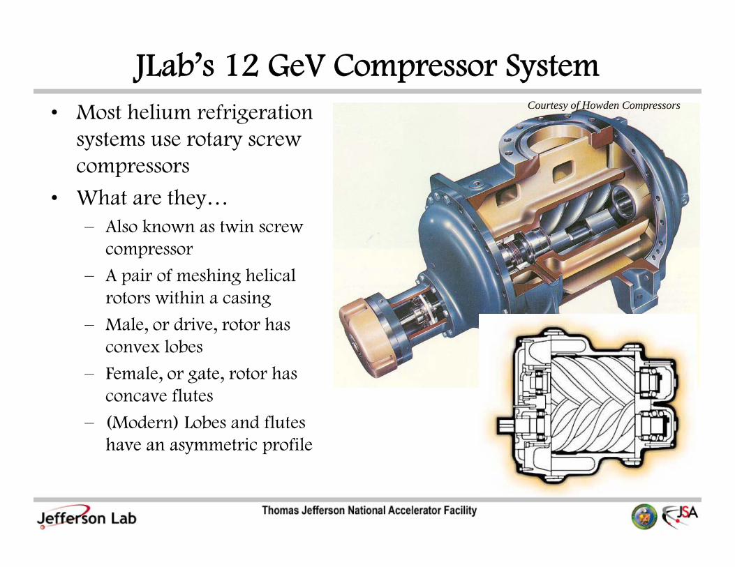
JLab’s 12 GeV Compressor Systemh li f i i Courtesy of Howden Compressors• Most helium refrigeration
systems use rotary screw compressors
Courtesy of Howden Compressors
p
• What are they…– Also known as twin screw
compressorcompressor
– A pair of meshing helical rotors within a casing
M l d i t h – Male, or drive, rotor has convex lobes
– Female, or gate, rotor has fl tconcave flutes
– (Modern) Lobes and flutes have an asymmetric profile

JLab’s 12 GeV Compressor System• What are they• What are they…
– Basic rotor characteristics
• # male lobes, # female flutes
» 4+6 (or 4/6) is common
• rotor (male) diameter (D)
• (L/D) – length to rotor diameter ratio( ) g
» ~1.4 to 2.1
• Wrap (or helix) angle
» typically 300° for compressors)» typically 300° for compressors)
• Built-in-volume ratio (BVR)
» ~2.1 to 5.8
• Usually directly coupled to an electric motor
» Requires ~80% starting torque
» This allows across the line starting (i.e., no transformer is g ,required)

JLab’s 12 GeV Compressor Systemh h• What are they… Courtesy of Sullair
Note: Also, http://www.youtube.com/watch?v=zQd-BTxNQHU(last accessed 17-Aug-2011)
JLab’s 12 GeV Compressor SystemA i t i / f tl il bl• Approximate size/performance range presently available,– Rotor diameters, ~50 to 800 mm (male)– Capacities, ~0.6 to 600 m3/minp ,– Pressure Ratio, ~3.5 for dry, up to ~15 for oil-flooded– Nominal pressure difference, up to ~15 bar
d b– Max. pressure difference, ~40 bar– Volumetric efficiencies ≈ 90%
• UsedUsed,– Widely, in the process industry; especially in commercial
refrigeration and the oil & gas industryA i – As air compressors
– For supercharging internal combustion engines– As expandersAs expanders

JLab’s 12 GeV Compressor SystemT• Types– Dry, Oil-Free
• One rotor drives other using timing gears (to prevent g g g ( pphysical contact of rotors)
• Use seals to prevent oil lubricating the bearings and gears from entering the processfrom entering the process
• Are considerably more expensive to manufacture than oil-flooded
– Lubricated or Oil-Flooded• Oil enters through bearings and/or by direct injection into
compression cavityp y• Development of the successful lubricated screw compressor
has been the most important development in its history – by increasing obtainable pressure ratios with moderate increasing obtainable pressure ratios with moderate discharge temperatures

JLab’s 12 GeV Compressor Systemh h• What are they…
– They are positive displacement devices
CompressorsTwin Screw
Compressors
R di l Fl A i l Fl i i
Aerodynamic Positive Displacement
R Li id di
Oil Free Lubricated
Radial Flow (Centrifugal)
Axial Flow ReciprocatingRotary
Two RotorSingle Rotor
Dry Liquid Injected (Not Oil)
Medium-Press. Air
& Gas
High-Press. Gas & Refrig.
Sliding V
Liquid Ri
Roots Screw
g
Vane Ring

JLab’s 12 GeV Compressor Systemh h• What are they…
– As compared to a piston compressor
• Fewer moving parts• Fewer moving parts
– Typical MTBF for those used in helium systems is ~60,000 hrs
• Dynamic balance and low vibration; since it is rotary and has effectively continuous flow
Hi h ti d• Higher operating speed
• No clearance volume (at the end of the stroke)
• Can tolerate ingestion of liquid in an amount that would • Can tolerate ingestion of liquid in an amount that would damage a piston machine

JLab’s 12 GeV Compressor Systemh h• What are they…
– As compared to centrifugal compressors
• Does not surge• Does not surge
• Can tolerate higher levels of liquid ingestion
• Lower operating speed; screw compressors can be directly p g p ; p ycoupled to an electric motor
– As compared to vaned compressors
• Contact forces are low
– As compared to piston, scroll and vaned compressors
C t t li li l th d th i • Contact sealing line length decreases as the compression volume decreases; so as the pressure is increasing, the area available for gas leakage decreases

JLab’s 12 GeV Compressor Systemh h• What are they…
– Typical characteristic of positive displacement vs. aerodynamic (centrifugal) devices Pi Oil Fl d d(centrifugal) devices
• Pressure vs. flow rate
Surge
PistonCompressor
Oil-FloodedScrewCompressor
ssur
e
SurgeLimit
p
Pres
CentrifugalCompressor
Volume Flow

JLab’s 12 GeV Compressor System1878 G t t b H K i• 1878 German patent by Herr Krigar– 2 male lobes + 2 female flutes (2+2, or 2/2)– Produced ~1.5 psi and was ‘quiet’p q

JLab’s 12 GeV Compressor SystemD l d f d d b Alf L h l i th 1930’ • Developed of modern screw compressor was done by Alf Lysholm in the 1930’s, the chief engineer of the Swedish company then called The Ljungström Steam Turbine Company – now called Svenska Rotor Maskiner (SRM) AB
Fi t L h l 3+3 t d i il f hi d 2 1 i ti– First Lysholm 3+3 rotor design, oil-free, achieved 2:1 compression ratio
– First application was for turbo-prop engines
– Tried asymmetric and symmetric circular rotor profiles

JLab’s 12 GeV Compressor System1946 S i d d i i l fil hi h• In 1946 SRM introduced symmetric circular rotor profile, which
had less risk of damaging the sealing edges due to thermal distortion or errors in timing of rotors (still an oil-free design)g g
– 4+6 rotor common, with both rotors of the same outside diameter
Female Rotor Male Rotor
Ref. O’Neil, P., “Mechanical design and efficiency of screw compressors”, presented at the Institution of Mechanical Engineers, London, 1966, p.4 Fig 1(b)

JLab’s 12 GeV Compressor SystemOil fl d d i d d i 1960’• Oil-flooded compressors introduced in 1960’s
• In 1960’s SRM introduced the SRM asymmetrical rotor profile, which did not have the draw backs of Lysholm’s asymmetric which did not have the draw backs of Lysholm s asymmetric profile (abandoned in the late 1940’s), resulting in 10-15% less power consumption than the symmetric circular profile
l d h d h h• Two factors accelerated the adoption of these machines– By the mid-1960’s milling machines for thread cutting enabled the rotors to
be manufactured accurately and with acceptable cost
– In 1973, SRM introduced the SRM “A” profile, an asymmetric profile which reduced the internal leakage path area (known as the ‘blow hole’) by 90%.
• This allowed the screw compressor to be built with efficiencies about pequal to piston compressors and with stage pressure ratios of up to 8:1 in the oil-flooded type
• This was unattainable using piston compressorsg p p

JLab’s 12 GeV Compressor Systemhi i ll l i h• Present machining accuracy allows tolerances in rotor on the
order of 5 μm (0.2 mils), or better
• For an efficient screw compressor, rotor profile must have,For an efficient screw compressor, rotor profile must have,
– Large flow cross-sectional area
– Short sealing line
– Small “blow-hole” area
• Although 4+6 configuration with male and female rotors having l t id di t i equal outside diameters is very common
» 4+5 configuration appears the best for oil-flooded types at moderate pressure ratiosmoderate pressure ratios
» 5+6 configuration is becoming the most popular, both as an air compressor and for refrigeration and AC

JLab’s 12 GeV Compressor Systemi fi i• Various rotor configurations
SRM Symmetric Circular
Lysholm’sAsymmetric
SRM “A” Profile Hyper ProfileSRM A Profile Hyper Profile
Ref. N. Stosic, I. Smith, A. Kovacevic, “Screw Compressors: Mathematical Modeling and Performance Calculation,” Springer, 2009, p. 16, Fig. 1.6,

JLab’s 12 GeV Compressor SystemF h il fl d d• For the oil-flooded type,
– Contact force is small if the male rotor is driven; however, contact force is substantially higher if the female rotor is contact force is substantially higher if the female rotor is driven
– Same oil used for bearing lubrication and oil flooding of rotors
– Oil is injected where (calculations indicate) gas and oil temperatures are equal
Injection holes located so that oil enters tangentially in line – Injection holes located so that oil enters tangentially in line with female rotor tip, in the direction of the advancing helix
– Even though oil removes ~85% (in helium applications) of ginput power (as heat), the actual volume of oil as compared to the total displaced volume is less than 1%

JLab’s 12 GeV Compressor SystemC i l• Capacity control
– Achieved using,
• On/Off operation• On/Off operation
• Inlet throttling
• Slide valve – shortens the effective length of the rotorsg
• Variable speed (VFD)
Effic
ienc
yE
00 Rotor Tip Speed
Ref. E.A. Avallone, T. Baumeister III (Eds), “Mark’s Standard Handbook for Mechanical Engineers,”, 10th Ed., p.14-35, Fig. 14.3.17, McGraw-Hill
0 Rotor Tip Speed

JLab’s 12 GeV Compressor SystemC it t l• Capacity control…– Effect of capacity control on input power required
100100Inlet Valve Throttling
ower
[%]
Slide Valve
Inpu
t Po
Average for On/Off Line
0
On/Off Line
0 0 Capacity [%] 100

JLab’s 12 GeV Compressor SystemB ilt i l ti (BVR) “V ”• Built-in volume ratio (BVR) or “Vi”– It is common nowadays for this to be adjustable (though in
some cases, not while running)– Three cases:
• Over-compressionUnder compression• Under-compression
• Matched-compression ► minimum p–V work– In general, it is better to under-compress,g , p ,
• Since the effect on the efficiency is less influential, and• To avoid extreme discharge temperatures (especially for
helium γ=1 67)helium, γ=1.67)• Effect on the thrust bearings is less

JLab’s 12 GeV Compressor Systemil l i ( )• Built-In Volume Ratio (BVR)
Ref. J.W. Pills, “Development of a Variable Volume Ratio Screw Compressor,” IIAR Annual Meeting, April 17-20, 1983, p. 8, Fig. 5 & 6

JLab’s 12 GeV Compressor SystemEff f dj ffi i i• Effect of BVR adjustment on efficiency vs. pressure ratio
Variable Volume RatioVariable Volume Ratio
Increasing Fixedffic
ienc
y
Increasing Fixed Volume RatioE
f
0Pressure Ratio
01

JLab’s 12 GeV Compressor Systeml di f i• Pressure-volume diagram of compression process
Additional Work Due pD,o
pD,m = pD
to Over-compression
Additional Work Due V = V / VAdditional Work Due to Under-compression
Compression WorkpD,u
VD,m = VS / Vi
Subscripts:
p·Vk = C0
pS – SuctionD – Dischargem - Matched
pS
VV
u – Undero - Over
VSVD,mVD,o VD,u

JLab’s 12 GeV Compressor SystemEff f l i ffi i (k) fi l i• Effect of polytropic coefficient (k) on final compression temperature

JLab’s 12 GeV Compressor System( h i l) i i d fi d• (Physical) exergy per unit mass is defined as,
ε = h - T0·swhere T is the reference temperature; i e environmental – where, T0 is the reference temperature; i.e., environmental temperature; say, 300 K
– exergy (ε) is an intrinsic fluid property (…like h and s)
• The minimum input power theoretically required; or conversely, the maximum power output theoretically possible is,
ΔΕ W W Σ Σ ΔΕ = Wout,max = –Win,min = Σ min·εin – Σ mout·εout
– also, known as the reversible (input or output) power
W
Processminε
moutε
Wout,max
εin εout

JLab’s 12 GeV Compressor SystemA f ffi i i h i f h id l• A common measure of process efficiency is the ratio of the ideal (or theoretical) input power to the actual (or real) input power required; known as the overall exegetic efficiency,q ; g y,
ηC = ΔΕ / Win
– Where, Win is the actual (real) required input power
• For compressors, three efficiencies are commonly used,
– Isothermal efficiency, T = constant
ΔΕ / W h ΔΕ i h diff TηT = ΔΕT / Win ; where, ΔΕT is the exergy diff. at const. T– Adiabatic efficiency, s (entropy) = constant
η = ΔΕ / W ; where ΔΕ is the exergy diff at const sηs = ΔΕs / Win ; where, ΔΕs is the exergy diff. at const. s– Volumetric efficiency; ratio of measured (actual) mass flow to
theoretical (as calculated from the displacement and speed)
ηv = mactual / mtheoretical

JLab’s 12 GeV Compressor SystemF id l th ti f th i th l t di b ti k i• For an ideal gas, the ratio of the isothermal to adiabatic work is,
(WT / Ws) = (ηT / ηs) = φ·ln(pr) / {prφ – 1}
– Where, φ = (γ – 1) / γ (= 0.4 for helium)
γ is the ratio of specific heats (= 1.67 for helium)
pr is the discharge to suction pressure ratio
– Note that (WT / W ) < 1 for p > 1; so, isothermal compression is the Note that (WT / Ws) 1 for pr 1; so, isothermal compression is the optimum process
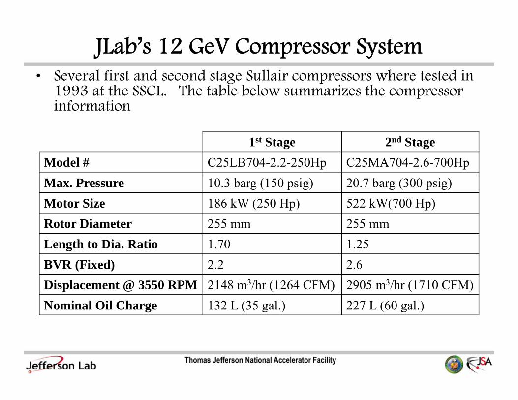
JLab’s 12 GeV Compressor System• Several first and second stage Sullair compressors where tested in • Several first and second stage Sullair compressors where tested in
1993 at the SSCL. The table below summarizes the compressor information
1st Stage 2nd StageModel # C25LB704-2.2-250Hp C25MA704-2.6-700HpMax. Pressure 10.3 barg (150 psig) 20.7 barg (300 psig)Motor Size 186 kW (250 Hp) 522 kW(700 Hp)Rotor Diameter 255 mm 255 mmRotor Diameter 255 mm 255 mmLength to Dia. Ratio 1.70 1.25BVR (Fixed) 2.2 2.6Displacement @ 3550 RPM 2148 m3/hr (1264 CFM) 2905 m3/hr (1710 CFM)Nominal Oil Charge 132 L (35 gal.) 227 L (60 gal.)

JLab’s 12 GeV Compressor Systeml i ffi i i ( ) h d d• Volumetric efficiencies (ηv) – note the strong dependence on pr,
and weaker dependence on discharge pressure
Note: Optimum in the neighborhood of p = 3 to 41st Stage 2nd Stage
Note: Optimum in the neighborhood of pr 3 to 4

JLab’s 12 GeV Compressor Systemh l ffi i i ( ) h d d• Isothermal efficiencies (ηT) – note the strong dependence on pr,
and weaker dependence on discharge pressure
Note: Optimum in the neighborhood of p = 3 to 4
1st Stage 2nd Stage
Note: Optimum in the neighborhood of pr 3 to 4

JLab’s 12 GeV Compressor SystemC 1 d i d i h• CHL-1 was designed with,
– 2nd stage, pr = 7.34; ηv ≈ 82%, ηT ≈ 47%
• CHL 2 id designed with• CHL-2 id designed with,
– 2nd stage, pr = 3.2; ηv ≈ 87%, ηT ≈ 57%

JLab’s 12 GeV Compressor System’ j Cold Box• It’s just a
compressor…right ? CompressorsCold Box
• It’s not even cryogenic…
• OK, we need one but what does it but…what does it really do? Load
Compressors
Cold Box
Load
Increase Exergy Use Exergy
Compressors Load

JLab’s 12 GeV Compressor SystemE l C 2 d ( d i321/165)• Example: CHL 2nd stage compressor (Howden WRVi321/165)
• A lot of power goes in…but where does it go?
Wi = 1.4 MW1st Law:Wi = m ·Cp· (TD – TS)1.4 MW = 0 ???
Discharge:pD = 18.5 atmT 310 K
Suction:pD = 2.5 atm
310TD = 310 K TD = 310 K
TD = TS

JLab’s 12 GeV Compressor SystemTh i i h “ i l ” f h ki• The input power increases the “potential energy” of the working fluid, and is dissipated as heat to the ambient environment
• How does this work (with all the input power is dissipated as How does this work (with all the input power is dissipated as heat)? Wi = 1.4 MW
1st Law:
q = 1.4 MW
1 Law:Wi = m ·Cp· (TD – TS) + q1.4 MW = 0 + 1.4 MW
Discharge:pD = 18.5 atmT 310 K
Suction:pS = 2.5 atmT 310 KTD = 310 K TS = 310 K
TD = TS ► Wi = q
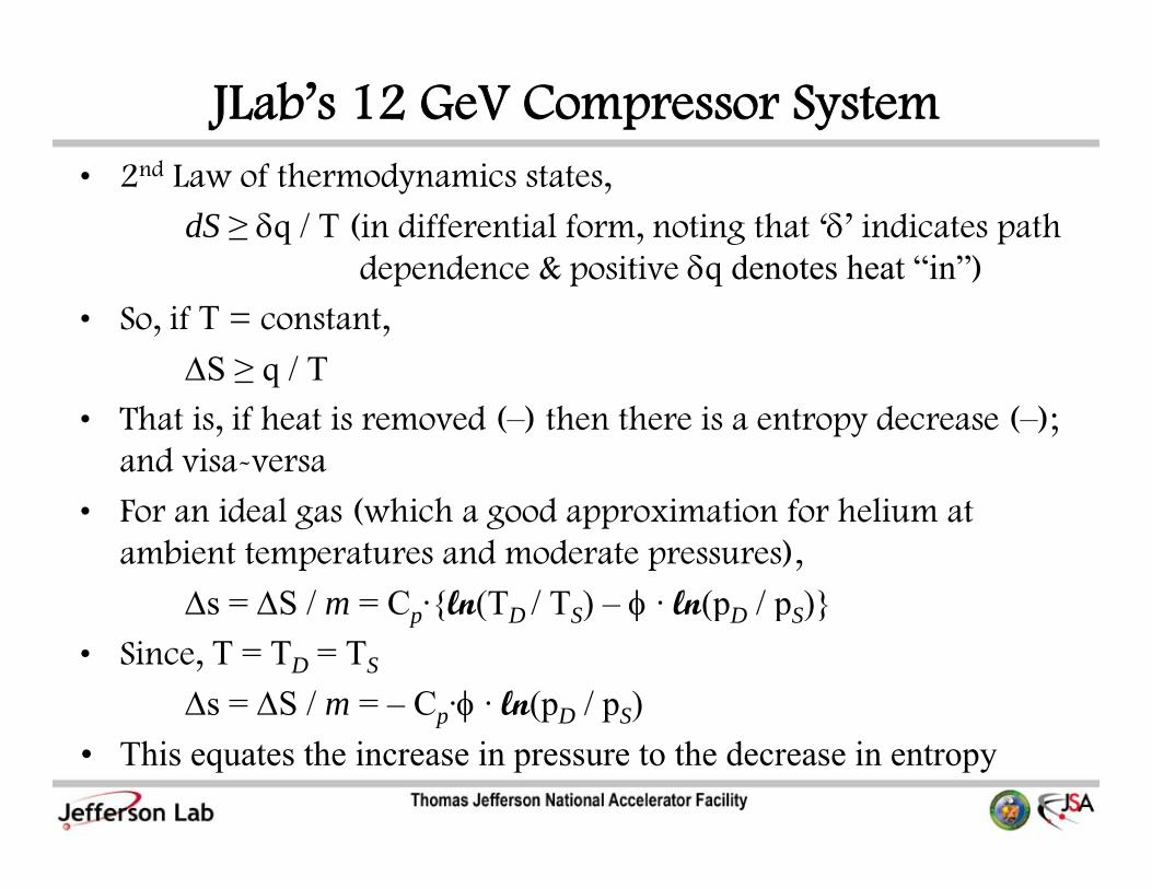
JLab’s 12 GeV Compressor System2 d f h d i• 2nd Law of thermodynamics states,
dS ≥ δq / T (in differential form, noting that ‘δ’ indicates path dependence & positive δq denotes heat “in”)dependence & positive δq denotes heat in )
• So, if T = constant,
ΔS ≥ q / T• That is, if heat is removed (–) then there is a entropy decrease (–);
and visa-versa
F id l ( hi h d i ti f h li t • For an ideal gas (which a good approximation for helium at ambient temperatures and moderate pressures),
Δs = ΔS / m = Cp·{ln(TD / TS) – φ · ln(pD / pS)}Δs ΔS / m Cp {ln(TD / TS) φ ln(pD / pS)}• Since, T = TD = TS
Δs = ΔS / m = – Cp·φ · ln(pD / pS)p
• This equates the increase in pressure to the decrease in entropy

JLab’s 12 GeV Compressor SystemS• So,
–q ≥ –T· ΔS = m ·φ·Cp·T·ln(pD / pS)• Recalling the definition of exergy and assuming an ideal gas• Recalling the definition of exergy, and assuming an ideal gas,
Δε = Δh – T0·Δs = Cp·(TD – TS) –T0· φ·Cp·ln(pD / pS)Δε = – T0·Δs =–T0· φ·Cp·ln(pD / pS)0 0 φ p (pD pS)
• If, TS = T0,
Δε = – TS·Δs =–TS· φ·Cp·ln(pD / pS)p
• And, using the 1st law and the definition of isothermal efficiency,
–q = Wi = ΔΕ / ηT = m · Δε / ηT = m ·φ·Cp·T·ln(pD / pS) / ηT
Heat dissipated “Potential energy” to environment increase of fluid

JLab’s 12 GeV Compressor Systemh did ll h i b f h 2 d f• Where did all that input power go, because of the 2nd Law of
Thermodynamics…
CHL Evaporative Cooling TowersCHL Evaporative Cooling Towers

JLab’s 12 GeV Compressor SystemTh f ll i h h i l 1 k f li• The following shows the input power losses per 1 kW of cooling at 2.1 K (0.039 atm) for CHL-1 (existing) and (estimated) for the new CHL-2
• Over half of the input power is lost in the compressor system!

JLab’s 12 GeV Compressor SystemA i t t id• As an important aside,– Assuming a thermal power plant to electrical conversion +
distribution efficiency of 33% (†),– Every 1 kW of cooling at 2.1 K requires,
• ~17 metric tons/day of lignite coal (‡) using “a CHL-1”12 metric tons/da of lignite coal (‡) using “a CHL 2”• ~12 metric tons/day of lignite coal (‡) using “a CHL-2”
Both providers and users of the cryogenic load Both providers and users of the cryogenic load need to be good stewards!
(†)Assuming the coal power plant ‘heat rate’ (amount of fuel heat content in Btu per amount of electric energy produced in kWh) is 9300 Btu/kWh HHV (higher heating value; i.e., water vapor in combustion products) and the electric transmission loss is ~8%the electric transmission loss is ~8%(‡)Average in the U.S.; Lignite coal = 15 MJ/kg

JLab’s 12 GeV Compressor SystemS h f ll h i i f h• So, hopefully we now have an appreciation of the,
– The role that the compressor system plays in a helium refrigerator – that it is the “heart” of the system, providing the refrigerator that it is the heart of the system, providing the rest of the system the “potential energy” (i.e., exergy) required for the process, and,
h l l h– The relative portion of power lost in the compressor system due to its inefficiencies, as compared to the rest of the helium refrigeration systemg y
– The impact of the total energy demand required by the 2-K process
• What are the inefficiencies in the compressor system, and what can be done to reduce them ?can be done to reduce them…?

JLab’s 12 GeV Compressor SystemOb i l ff b i i i h d i b• Obviously, effort can be given to improving the rotor design…but we will leave that to the manufacturers
• A compressor is more than just the compressor proper; i.e., it is a A compressor is more than just the compressor proper; i.e., it is a skid – a package, comprising a number of (major) components

JLab’s 12 GeV Compressor SystemOf d i i h i i• Often, a good starting point to answer such a question is to carefully examine existing designs
• So, based upon the experience fromSo, based upon the experience from
– (4) different compressor and skid manufacturers that support
– (5) cryogenic plants (at JLab), as well as, from many other facilities,
– A number of observations were made over the years of their operationoperation
– Each of these were addressed in the compressor system designed by the JLab cryo group for the James Webb telescope g y J y g Jtesting to be conducted at the NASA-Johnson Space Center
– JLab’s 12 GeV compressor system directly benefits from this design effort funded by NASA!design effort funded by NASA!

JLab’s 12 GeV Compressor System• The following are (10) observations and how they were addressed • The following are (10) observations and how they were addressed
for the 12 GeV compressor skids (to be used for the new cold box)– Observation #1: A proper alignment can be difficult to achieve due to,
• An uneven or sloped compressor and/or motor mounting plate and due to the way in which the compressor is attached to the rest of the skid
• Misalignment due to thermal expansion (i.e., mounting compressor and motor on bulk oil separator)
– Of course, the life of the bearings is significantly affected by the quality and preciseness of the alignment
– Response to #1:• A universal adjustable steel chock is used under each foot for the • A universal adjustable steel chock is used under each foot for the
compressor and motor mounting thereby eliminating parallel and/or angular soft-foot
• Compressor and motor are physically separate from the BOS to reduce • Compressor and motor are physically separate from the BOS to reduce misalignment due to thermal expansion

JLab’s 12 GeV Compressor SystemOb i #2 OS’ i ll d f h k h– Observation #2: BOS’s typically used for these packages have a large diameter and flanges and utilize fragile glass-fiber coalescing filters to remove oil from helium prior to entering g p gafter-cooler (presumably for improved heat transfer)
– However, even with the coalescing filters, the after-cooler heat transfer surface is coated ith oiltransfer surface is coated with oil
BOS
BOS

JLab’s 12 GeV Compressor System#2 OS d l fib fil f i– Response to #2: BOS does not use glass-fiber filters. Referring
to the figure below, the first stage separation is cyclonic as the helium enters the BOS
– Then the flow is distributed from horizontal supply header into the horizontal vessel at a slight downward angle, then gathered in the o erhead return headerin the overhead return header
Helium In (from Compressor Discharge)
Helium Out (to A/C)Return Headers
Oil WeirOil Weir
Oil Out (to O/C)Gravity Separation Section
Oil Flow
Cyclonic Separation Section( )
Supply HeadersGravity Separation Section
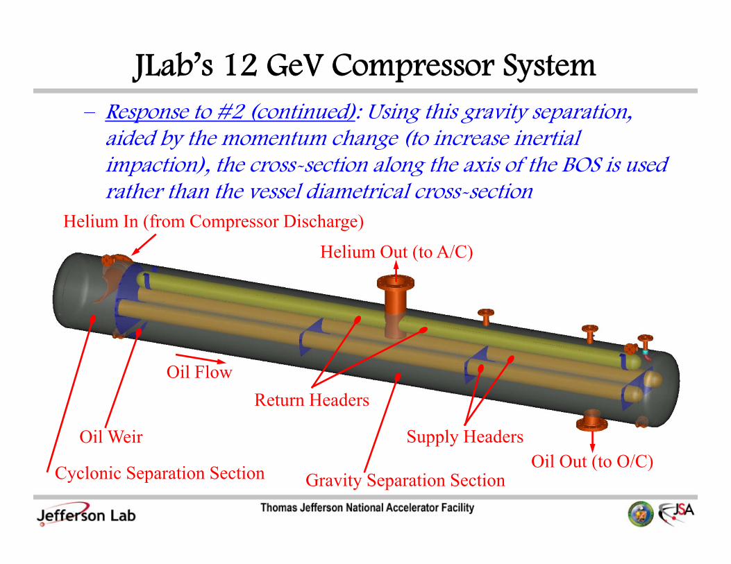
JLab’s 12 GeV Compressor System#2 ( i d) i hi i i– Response to #2 (continued): Using this gravity separation,
aided by the momentum change (to increase inertial impaction), the cross-section along the axis of the BOS is used p , grather than the vessel diametrical cross-section
Helium In (from Compressor Discharge)
H li O ( A/C)Helium Out (to A/C)
Oil Flow
Oil Out (to O/C)Supply Headers
Return Headers
Oil Weir
Cyclonic Separation Section Oil Out (to O/C)Gravity Separation Section

JLab’s 12 GeV Compressor System#2 ( i d) C l f i h– Response to #2 (continued): Consequently, referring to the
table below, the BOS diameter is quite small and does not use large flanges as compared to typical BOS’sg g p yp

JLab’s 12 GeV Compressor SystemOS i i i d i l• BOS gravity separation section design goals
– Minimize pressure drop, while
Keeping flow distribution as even as possible and– Keeping flow distribution as even as possible, and
– Selecting an practical hole size and spacing
– Keep total orifice area ≥ header cross-sectional flow parea
– Keep in mind that inlet static pressure difference in l h d ill di tl ff t il h i ht diff supply header will directly affect oil height difference
between cyclonic and gravity sections (which are separated by a weir)y
– Orient header orifices to facilitate droplet inertial impaction by maximizing directional change in momentummomentum

JLab’s 12 GeV Compressor SystemCHL 2 HP kid BOS it ti ti l & t • CHL-2 HP skid BOS gravity separation section, supply & return header flow distribution (design)

JLab’s 12 GeV Compressor SystemC 2 kid OS i i i h d• CHL-2 HP skid BOS gravity separation section header design – flow modeling, 1D with tangential mass subtraction (or addition)
– Note that for the supply header, the effect of the mass leaving tangentially is known as ‘wall suction’; and its net effect is to increase wall fraction
– The converse is true for the return header (though it is known as “wall blowing”)
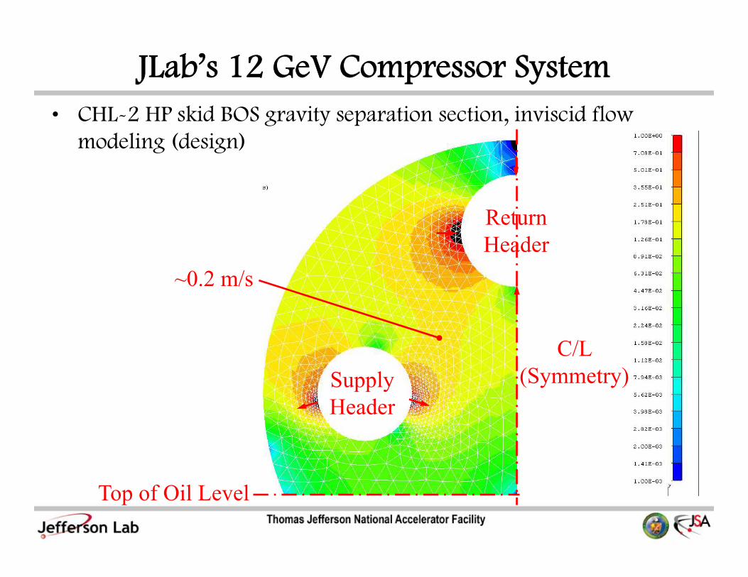
JLab’s 12 GeV Compressor SystemC 2 kid OS i i i i i id fl• CHL-2 HP skid BOS gravity separation section, inviscid flow modeling (design)
Return Header
~0.2 m/s
Supply C/L
(Symmetry)Header
Top of Oil Level

JLab’s 12 GeV Compressor SystemE i i f il f OS kid• Estimation of oil carry-over from BOS; e.g., HP skid– Estimate Sauter droplet diameter
D32 = 94 to 233 μm [Ref. Perry’s, 7th Ed., equs. 14-199,198,200]32 μ y , , q , ,
– Estimate max. droplet size given velocity field (which is used as the terminal settling velocity)
D = 78 μm [Ref. Perry’s, 7th Ed., equ. 6-228]Dp,max 78 μm [Ref. Perry s, 7 Ed., equ. 6 228]
– Assuming a droplet size distribution, the mass fraction of oil not separated can be estimated
Δ = (D /D ) = 0 824 (using smallest D )Δ = (Dp,max/D32) = 0.824 (using smallest D32)
fo (mass frac. of oil not sep.) = 1 – exp(-c0·Δ3) = 0.533• with, c0 = Γ(5/3)-3 = 1.359• Ref. C. Dumouchel, “The Maximum Entropy Formalism and the
Prediction of Liquid Spray Drop-Size Distribution”, Entropy, 11, 2009, p.713-747, equ. 27

JLab’s 12 GeV Compressor System#2 ( i d) Addi i ll i i l– Response to #2 (continued): Additionally, an intentional
provision is made in the after-cooler to drain coalesced oil due to momentum changes in the boundary layer and increased g y ycoalescence as the oil surface tension and its viscosity increases as it is cooledSince oil is present ith or ithout the coalescing filters in the – Since oil is present, with or without the coalescing filters in the BOS, the after-cooler is sized assuming 0.2% of oil (by weight of helium)

JLab’s 12 GeV Compressor System#2 ( i d) A l b i ll– Response to #2 (continued): An external, but not integrally
attached to the skid, vertical gas-fiber coalescer filter is located downstream of the after-cooler which is capable of being p glocated in a convenient and unobtrusive location in order to maintain the skid compressor oil balance locallyThe coalescer efficienc is impro ed for the same size since the – The coalescer efficiency is improved for the same size since the helium-oil mixture is at a lower temperature (and a higher density)
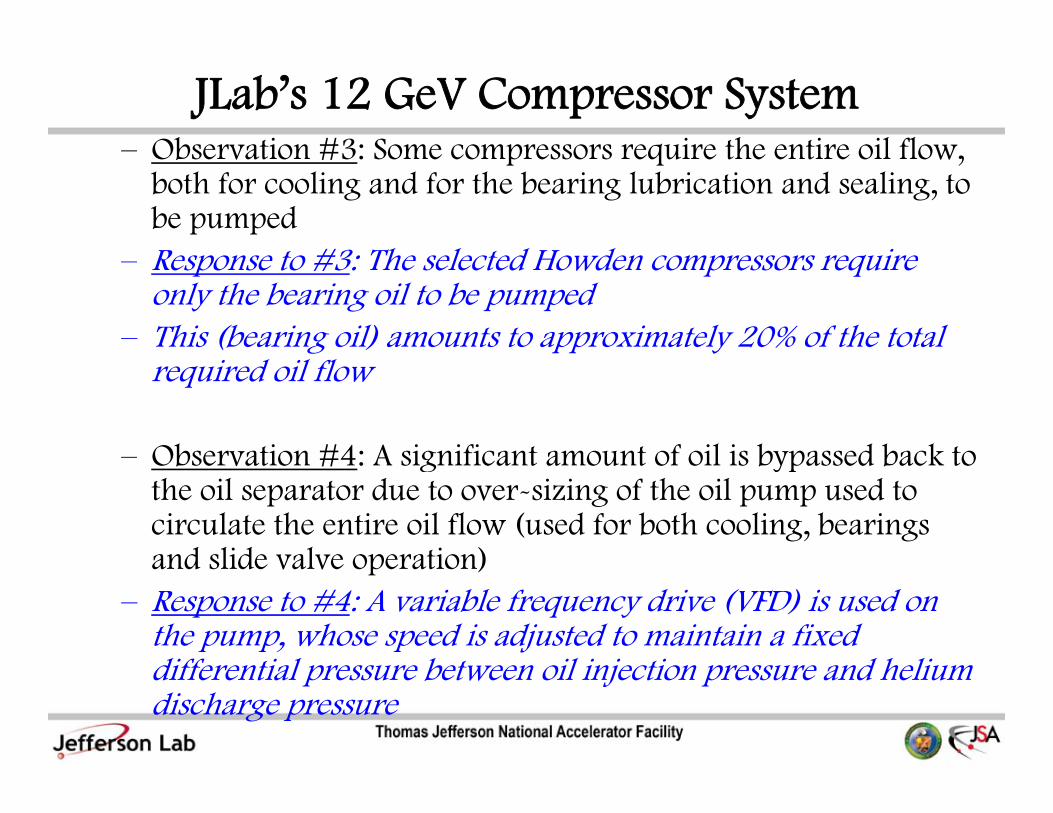
JLab’s 12 GeV Compressor System– Observation #3: Some compressors require the entire oil flow – Observation #3: Some compressors require the entire oil flow,
both for cooling and for the bearing lubrication and sealing, to be pumpedR t #3 Th l t d H d i – Response to #3: The selected Howden compressors require only the bearing oil to be pumped
– This (bearing oil) amounts to approximately 20% of the total required oil flow
– Observation #4: A significant amount of oil is bypassed back to Observation #4: A significant amount of oil is bypassed back to the oil separator due to over-sizing of the oil pump used to circulate the entire oil flow (used for both cooling, bearings and slide valve operation)and slide valve operation)
– Response to #4: A variable frequency drive (VFD) is used on the pump, whose speed is adjusted to maintain a fixed diff ti l b t il i j ti d h li differential pressure between oil injection pressure and helium discharge pressure

JLab’s 12 GeV Compressor SystemOb i #5 Oil i f l d f h il– Observation #5: Oil pump is often located upstream of the oil cooler to reduce the required input power by pumping the fluid when it is less viscous
– However, this results in handling the oil when it is still at its peak temperature
l k h h ll d l– Consequently, it is known that these pumps will develop more frequent shaft seal leaks
– Response to #5: The oil pump is located downstream of oil cooler and is significantly smaller, handling only the oil required for the bearings (i.e.,~20% of the total oil flow)
– Also, the additional input power required for pumping the oil when it is cooler amounts to only a modest amount (perhaps when it is cooler amounts to only a modest amount (perhaps 5% more than if it were pumped upstream of the oil cooler)
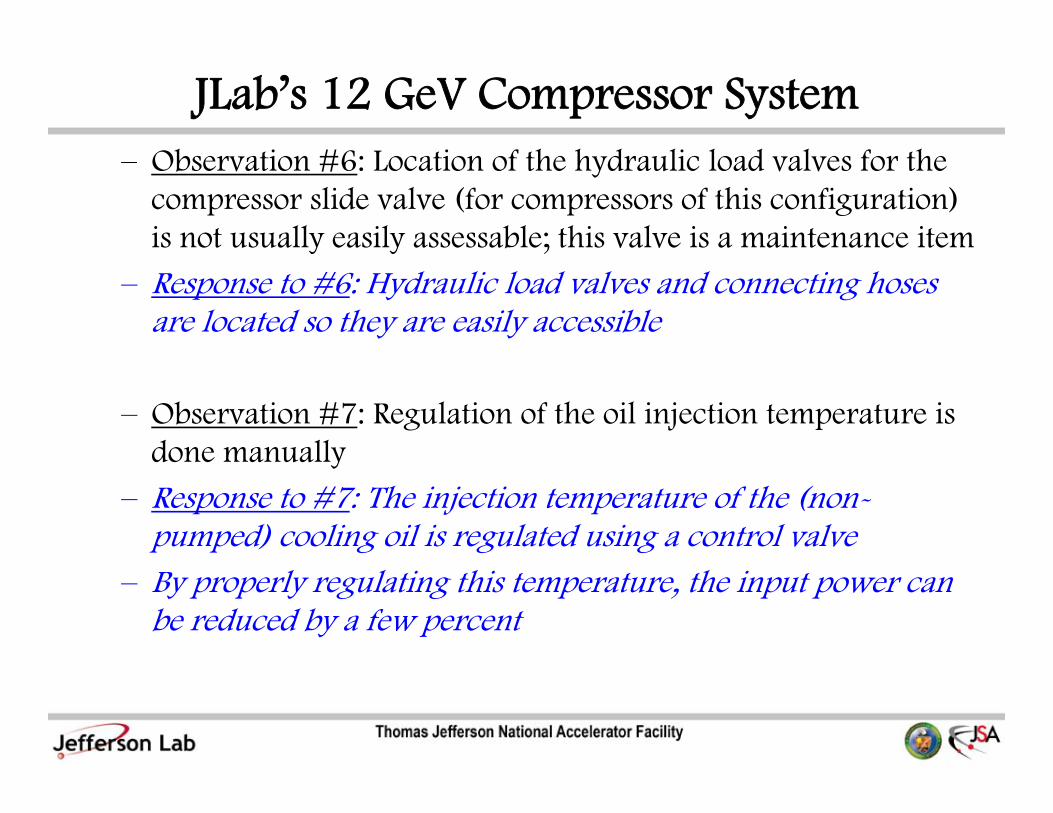
JLab’s 12 GeV Compressor SystemOb i #6 i f h h d li l d l f h– Observation #6: Location of the hydraulic load valves for the compressor slide valve (for compressors of this configuration) is not usually easily assessable; this valve is a maintenance itemy y ;
– Response to #6: Hydraulic load valves and connecting hoses are located so they are easily accessible
– Observation #7: Regulation of the oil injection temperature is done manuallydone manually
– Response to #7: The injection temperature of the (non-pumped) cooling oil is regulated using a control valve
– By properly regulating this temperature, the input power can be reduced by a few percent

JLab’s 12 GeV Compressor SystemOb i #8 Oil l d f l h– Observation #8: Oil coolers and after-coolers can have significant flow bypassing in the shell
– Also, the oil cooler can be undersized (which can result in a Also, the oil cooler can be undersized (which can result in a compressor shutting down on a hot day)
– Response to #8: Both oil and after coolers are a TEMA AEU design; i.e., channel and removable cover, one pass shell, U-tube bundletube bundle
– The oil cooler is sized for approximately 90% of the total compressor power

JLab’s 12 GeV Compressor SystemOb i #9 d il fil i h– Observation #9: Inadequate oil filtration to the rotors
– This can significantly affect the life of the bearings and rotor tolerancestolerances
– The filtration should be at least 30 microns
– Response to #9: Both cooling oil and bearing oil is filtered to 8 microns at 98% efficiency, with no significant pressure drop penalty (Δp /p < 2% for MP stage)penalty (ΔpD/pD < 2% for MP stage)
JLab’s 12 GeV Compressor SystemOb i #10 Th b l d i f il– Observation #10: There can be an apparent loss and gain of oil in the BOS when starting and stopping the compressor
– Response to #10: The oil cooler is at the lowest elevation and always kept full
– Skid components are arranged to allow the oil to completely drain by gravity to the BOS, which is immediately above the oil coolercooler
– Oil is not allowed to accumulate in other parts when the compressor is shut-down, so that there are no oil slugs upon start-up

JLab’s 12 GeV Compressor SystemH li Di h12 G Skid Helium Discharge
Electric MotorHelium After-C l (A/C)
12 GeV HP Skid
CWSCooler (A/C)
Helium Suction
Bulk Oil SeparatorSuction
Oil Cooler (O/C)
Separator (BOS)Oil Filter
Electrical C l l
CWR( )
Control Panel

JLab’s 12 GeV Compressor System12 G Skid Helium Discharge
Electric Motor H li AftBulk Oil
12 GeV HP Skid
CWSMotor Helium After-
Cooler (A/C)Bulk Oil
Separator (BOS)
Oil CoolerOil Cooler (O/C)
CWROil Filter Compressor
Helium Suction
Coupling
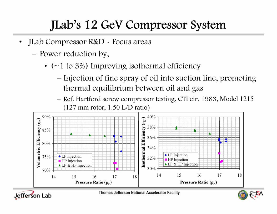
JLab’s 12 GeV Compressor SystemJL b C R&D F • JLab Compressor R&D - Focus areas
– Power reduction by,
• (~1 to 3%) Improving isothermal efficiency• ( 1 to 3%) Improving isothermal efficiency
– Injection of fine spray of oil into suction line, promoting thermal equilibrium between oil and gas
– Ref. Hartford screw compressor testing, CTI cir. 1983, Model 1215 (127 mm rotor, 1.50 L/D ratio)

JLab’s 12 GeV Compressor SystemT i C 1 2 d (C5) i321/165 2006• Testing on CHL-1 2nd stage (C5) WRVi321/165, Jan 2006
– For perfect oil-helium mixing during polytropic compression, kº ≈1.05k 1.05
JLab’s 12 GeV Compressor SystemJL b C R&D F • JLab Compressor R&D - Focus areas– Power reduction by,
• (~2 to 3%) Establishing optimum flow regulation of ( ) g p ginjected oil; i.e., increasing oil injection,
» Tends to improve the isothermal efficiency (i.e., the compression process becomes more isothermal) butcompression process becomes more isothermal), but
» Increases viscous friction (oil becomes cooler)» So, there is an optimum oil injection; this usually
corresponds to roughly an oil injection temperature of ~322 K (120 ºF)
– Note that using very high oil injection pressure to g y g j pachieve high atomization (of oil) does not improve the efficiency, since the gains in making the compression more isothermal are outweighed by the additional g ypower required to pressurize the oil

JLab’s 12 GeV Compressor SystemE i f di i d• Equation for power dissipated by a journal bearing, can be used to estimate oil viscous- UCON LB-170Xfriction power loss
P = N2 (πD)3 L μ / δh
UCON LB 170X
– Where,
• N – rotational speed
• D rotor diameter• D – rotor diameter
• L – rotor length
• μ – oil dynamic μ oil dynamic viscosity
• δ – clearance between d h i
Note: Dynamic viscosity is a Log scale
rotors and housing
JLab’s 12 GeV Compressor Systemb C & F• JLab Compressor R&D - Focus areas
– Power reduction by,
• (~1%) Reduction of wasted pressure drop in BOS• (~1%) Reduction of wasted pressure drop in BOS
– Promote increased inertial impaction in the separation of the oil from the helium without using coalescing filters (in the BOS and at elevated temperatures).
– Use, BOS with combined centrifugal (cyclonic) and gravity separation sections; gravity separation of oil fromgravity separation sections; gravity separation of oil from helium accomplished in a compact and efficient manner by using supply and return headers in a small diameter vessel; or by using multiple ‘trays’

JLab’s 12 GeV Compressor SystemEff f d d l OS d A/C– Effect of pressure drop due to valves, BOS and A/C downstream of compressor discharge is to increase the isothermal power requiredp q
• e.g., CHL-1, 2nd stage; pr = 7.2, ΔpD > 0.5 atm, (ΔpD/pS) > 0.2
• so, ~1.5% additional isothermal power is required due to the pressure dropdrop

JLab’s 12 GeV Compressor Systemb C & F• JLab Compressor R&D - Focus areas
– Increase capacity by,
• Improving volumetric capacity• Improving volumetric capacity
– Provide more phase interface surface area for at least the same contact time to promote the dissolution of helium from oil
– This is done in the BOS
JLab’s 12 GeV Compressor Systemb C & F• JLab Compressor R&D - Focus areas
– Increase performance by,
• Using coalescing elements at lower temperatures; rather than• Using coalescing elements at lower temperatures; rather than at the highest temperature (i.e., compressor discharge) in the BOS
• Increase bulk oil removal efficiency by utilizing the after-cooler to assist in oil-helium separation
Increase environmental safety by– Increase environmental safety by,
• Using a smaller BOS which allows a smaller oil charge in order to minimize the environmental impact due to oil leakage
JLab’s 12 GeV Compressor SystemS• Summary
– The compressor system is often considered a component not worth the same level of consideration as compared to the cold worth the same level of consideration as compared to the cold box
– Consequently, the helium compressor has not received the h ld bsame attention in R&D as the cold box
– However, it should!...since it,
• Provides the cold box the “potential energy” (exergy) and• Provides the cold box the potential energy (exergy) and,
• At least half of the input power is lost in the compressor systemy
• With increased awareness of energy usage and costs, this has been an ongoing area of active research and development for the JLab cryogenics groupdevelopment for the JLab cryogenics group