jk front bumper - · pdf filejk front bumper kit installation guide. page 2 of 24 ... 2....
TRANSCRIPT

Page 1 of 24
JK FRONT BUMPER KIT
Installation Guide

Page 2 of 24
EXPLODED VIEW SHOWN WITH OPTIONAL SKIDPLATE AND WINCH MOUNT

Page 3 of 24
PLEASE READ BEFORE YOU START
TO GUARANTEE A QUALITY INSTALLATION, WE RECOMMEND READING THESEINSTRUCTIONS THOROUGHLY BEFORE BEGINNING ANY WORK. THESEINSTRUCTIONS ASSUME A CERTAIN AMOUNT OF MECHANICAL ABILITY AND AREINTENDED FOR SOMEONE WHO IS FAMILIAR WITH AUTO BODY REPAIR ANDMECHANICS.
Bumper kit Components QTY
Front Bumper 1
Bumper brackets 2
Fog lamp brackets 2
Bumper spacers (3/8 inch) 2
Crush can covers 2
Mesh 1
Mesh attach screws 5
1/2 in.Large button head bolts 7
1/2 in.Short button head bolt 1
1/2 in. hex head bolts 4
1/2 in. locking nuts 9
1/2 in. Thin locking nuts 3
1/2 in. flat washers 15
3/8 in. hex head bolts 4
3/8 in. locking nuts 4
3/8 in. flat washers 8
1/2 in. bolts 8
1/2 in. flat washers 8
Winch mount components
1/2 in. hex head bolts 2
1/2 in. locking nuts 2
1/2 in. flat washers 4
Winch mount 1
Tow hook kit components QTY
Tow Hook, right 1
Tow Hook, left 1
1/2 in. hex head bolt 6
1/2 in. flat washer 16
1/2 in. locking nuts 4
1/2 in. thin locking nuts 2
Skid plate kit components
Skid plate 1
3/8 in thread cutting bolt 4
3/8 in. hex head bolt 4
3/8 in. flat washer 8
3/8 in. locking nut 4
Required Tools
Center Punch
Common Hand ToolsMetal Cutting Tool For Trimming(Die Grinder, Cut Off Wheel, Sawzall)
Touch Up Paint
File or De-Burring Tool
Jack or Lift
Wax pencil for marking holes
Drill Motor
Drill Bits

Page 4 of 24
REMOVAL OF THE FACTORY COMPONENTS
A. REMOVAL OF THE SKID PLATE
1. Remove the “scrivet” fasteners at the front of the skid plate. Use a Phillips screwdriver toback out the plastic pin and pull out the fastener. The pin will tend to spin. Use a flatscrewdriver under the base of the fastener to apply pressure as you turn the screw.

Page 5 of 24
B. REMOVAL OF THE FRONT BUMPER
1. Disconnect fog lamp wiring2. Remove the 8 nuts attaching the bumper to the frame rails3. Remove the plastic closeout panel in front of the grille.4. Remove steel backing plates from inside frame rail

Page 6 of 24
VEHICLE PREPARATION
A. MODIFY THE FOG LAMP WIRING
1. The fog lamps will be mounted further apart on your new AEV bumper, so the wiringharness needs to be re-positioned. This is accomplished by removing the factory conduitand re-routing the harness above the frame rails. DO NOT CUT THE HARNESS
2. Remove the tape from the wire harness at both ends to expose the loose wires3. Remove the fog lamps from the factory bumper and attach them to the brackets supplied
in the kit using the same screws4. Temporarily position the lamps on the frame to simulate their new installed position and
to give you a point of reference how long you need to make the new harness5. Route harness along bottom of grille and fasten to power steering line using tie straps6. Carefully re-position the harness so the connectors reach the new attaching points
Original wiring position Remove tape

Page 7 of 24
Original O.E. fog lamp shown on AEV fog lamp bracket
7. Re-tape and replace conduit on modified harness
New harness length Harness routed to fog lamps

Page 8 of 24
Fasten harness to power steering line Route as shown
B. FRAME RAIL PREPARATION
1. Depending on your application, you may need to enlarge the two outer most upperholes in the factory frame rail and supplied winch mount. Check this by inserting alarge bumper mounting bolt into the holes. If it does not pass freely through the holes,drill them out, de-burr, and apply rust inhibitor or touch up paint to prevent rusting
2. The passenger side factory frame rail tip may need to be trimmed depending on yourwinch selection. This example shows a Warn 9.5ti which required some trimming.
Drilling out the frame rail outer (upper) hole Drilling out the winch mount

Page 9 of 24
Front frame (detail shown below)
Close up of trimming area.** PLEASE NOTE - newer JK builds may already include this cutout **

Page 10 of 24
C: BUMPER PREPARATION
1. Your new AEV bumper was designed to accommodate the vehicle’s factory “crush cans”that are specifically tuned for the vehicle air bag performance in low speed impacts. Thecrush cans are integral to the factory bumper beam and must be removed and re-installed on your AEV bumper.
2. Remove the bumper beam mounting bolts from the factory bumper3. Remove bumper beam and place in a vise4. Scribe a line approximately 3/8 of an inch outside the mounting holes on the bumper
beam5. Using a reciprocating saw or cut off wheel, remove the crush cans from the bumper
beam, keeping the mounting holes in place6. Use template (found at the end of this Installation Guide) to trim crush cans7. Install the mesh into the bumper over the studs and tighten nuts8. De-burr all cut edges and treat with corrosion inhibitor or touch up paint9. Install crush cans into bumper10. Install crush can covers and tighten bolts

Page 11 of 24
Use paper template (last page of this instruction manual) to trim factory crush cans to the proper shape.Be certain to print this template at 100% and locate template off of bolt holes.
Double check the scale on your printout to be certain that your template is accurate.
Modified crush cans ready for installation

Page 12 of 24
Crush can covers (shown transparent), crush cans and perforated vent assembled into bumper and ready forinstallation onto vehicle

Page 13 of 24
INSTALLATION
A. INSTALL WINCH MOUNT
1. A fairlead should have been supplied with your winch. Install it to the winch mount,positioning the bolt from inside out
2. Place winch mount into position over the frame3. Install the 3/8 inch spacer plates supplied between the rail tips and winch mount4. Insert the (8) 1/2 inch bumper mounting bolts through the mounting holes5. Firmly clamp the winch mount to the vehicle6. Check mounting hole alignment by making sure all 8 bolts slide freely in and out of the
holes7. Un-clamp and re-position winch mount until the holes are properly aligned8. With the winch mount clamped and holes aligned, bolt the winch mount to the lower
frame attachment with a 1/2 inch hex head bolt9. Use a flat washer under the head of the bolt, and under the large locking nut. Use an
open end wrench to access the bolt head from the top of the frame rail10. Remove the 8 bumper mounting bolts and clamps

Page 14 of 24
Winch mount (shown transparent) placed on the end of the frame rails with 3/8” spacers in place

Page 15 of 24
B. INSTALL TOW HOOKS AND BUMPER BRACKETS
1. Place tow hook on the vehicle frame2. Install 1/2 inch hex head bolt into lower hole on the side of the tow hook3. While holding the tow hook into place against the frame, place a center punch through
the upper attachment hole and mark the vehicle frame. This hole will allow forclearance of the attaching bolt
4. Continue holding the tow hook in place and center punch the frame at the front lowertow hook attaching point
5. Remove the tow hook and drill the holes previously marked with a 1/2 inch drill bit. Itis much easier to drill a 1/8 inch pilot hole first
6. De-burr the drilled holes and paint them with corrosion inhibitor or touch up paint

Page 16 of 24
7. Place the tow hook back into position and install a 1/2 inch hex head bolt into the frontattachment point.
8. Place two washers between the tow hook and frame at this point to ensure a flatmounting surface
9. Install the bumper mounting brackets to the tow hook mounting holes10. Tighten the bolts, beginning with the lower outside. Use an open end wrench to
access the nut from the top of the frame rail11. Install the upper bolt, using the thin locking nut supplied in the kit12. Torque all bolts
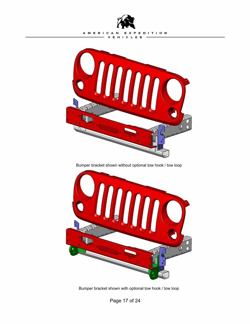
Page 17 of 24
Bumper bracket shown without optional tow hook / tow loop
Bumper bracket shown with optional tow hook / tow loop

Page 18 of 24
C. INSTALL BUMPER
1. Place winch onto winch mount. Route wiring over stabilizer bar. Do not install winchmounting bolts at this time
2. If you are using a roller style fairlead, removal of the vertical rollers will make bumperinstallation easier and help avoid scratching the bumper
3. Using the assistance of a helper, carefully set the bumper onto the vehicle. BECAREFUL NOT TO SCRATCH THE PLASTIC FENDER FLARES
4. Insert the 1/2 inch button head fasteners through the bumper, winch mount, spacerplate, and frame rail in all 8 locations
5. NOTE: THE SHORT BOLT SUPPLIED MUST BE USED IN THE PASSENGERSIDE UPPER MOST INNER LOCATION. USING A LONG BOLT HERE WILLINTERFERE WITH THE WINCH MOTOR
Example of how assembly should look prior to bumper fitment

Page 19 of 24

Page 20 of 24
6. Slide the winch to one side and reach behind the bumper from the top to access thethreads. Use flat washers and large locking nuts in all locations except for #5 above,which uses a thin locking nut and no washer
7. Tighten the 4 inner bolts slowly, while a helper makes sure the bumper is held in avertical position. The mounting face should be flat against the winch mount
8. Install the fog lights on the brackets and put them into place on the outer bumpermounting bolts
9. Place flat washers and large locking nuts on the outer bolts. Slowly tighten andtorque into place
10. After the face bolts are tight, use the 3/8 bolts, washers, and lock nuts to fasten therear bumper brackets to bumper
11. Re-attach fog lamp wiring12. Attach winch to winch mount using fasteners supplied by the winch manufacturer

Page 21 of 24
A. INSTALL SKID PLATE
1. Hold skid plate in position under bumper2. Insert two self threading hex head bolts into outer mounting holes3. Start threading bolts into position and snug. Do not tighten at this time4. Insert two self threading hex head bolts into the inner mounting holes under bumper5. While holding skid plate up tightly against underbody, mark the 4 rear mounting holes
and center punch6. Remove skid plate7. Drill holes marked in #5 using a 3/8 inch drill bit8. De-burr and treat holes with rust inhibitor or touch up paint9. Re-install skid plate10. Re-install the 4 self threading bolts in the front mounting holes11. Use (4) 3/8 inch bolts, flat washers, and locking nuts in the rear mounting location12. Torque all bolts

Page 22 of 24
Image enlarged below
- WARNING -Check for clearance between drag link adjuster clamps and
skidplate. Place bolts vertical and rearward.

Page 23 of 24
Completed Assembly

Page 24 of 24
COMMENTS OR QUESTIONS?
American Expedition VehiclesPhone: 406.251.2100Email: [email protected]: http://www.aev-conversions.com

CHECK PRINT SCALE
BOX SHOULD BE 1"
SQUARE.
1.00
1.00