jjl foreign technology · pdf filejjl foreign technology division ... forn ftd q.9 67 0-90....
TRANSCRIPT

FTD-MT-24-3o4-67
jjL
FOREIGN TECHNOLOGY DIVISION
GUIDANCE OF BALLISTIC MISSILES(Chapters 4-..5)
by
A. M. Zhakov and F. A. Pigulevskiy
19 17" 196~i7Got IN ANW " V IR S AA
FOREIGN TECHNOLOGY DIVISION
Distribution of this document isunIi.mritccd. It may be released to
Reprcoduced by the .....................fcFodeeaf Sreen,snc A Technical

FTD-MT- 24-3o4-67
EDITED MACHINE TRANSLATION
GUIDANCE OF BALLISTIC MISSILES (Chapters 4-5)
By: A. M. Zhakov and F. A. Pigulevskiy
English pages: 60
SOURCE: Upravleniye Ballisticheskimi Raketami,Voyennoye Izd-vo Ministerstva OboronySSSR, Moskva, 1965, pp. i-4 and 146-210.
TM7502000
THIS TRANSLATION IS A RENDITION OF THE ORIGI-NAL FOREIGN TEXT WITHOUT ANY ANALYTICAL OREDITORIAL COMMENT. STATEMENTS OR THEORIES PREPARED BYtADVOCATED OR IMPLIED ARE THOSE OF THE SOURCEAND DO NOT NECESSARILY REFLECT THE POSITION TRANSLATION DIVISIONOR OPINION OF THE FOREIGN TECHNOLOGY DI- FOREIGN TECHNOLOGY DIVISIONVISION. WP*AFB, OHIO.
FTO-MT-24-304-67 DIte 1 Dec 19 67

Iii
: This document is a machine translation
of Russian
text which has been processed by the AN/GSQ-I(,(XW-2)
MachIne Translator, owned and operated by the United
States Air Force. The machine output has beer post-
edited to correct for maor amblgaities of meaning,
words missing from the macnine's dictionary, and words
out of the context of meaning. The sentence word
order has been partially rearranged for readabillty.
The content cf this translation does not indicate
editorial accuracy, nor does it indicate USAF approval
or disapproval of the material translated.
\
t

ITIS INDEX CONTROL FORM
01 Acc Nr 68 Translation Nr 65 X Ref Acc Nr 76 Reel/Prame Nr
TM7502000 FTD-MT-24-304-67 I AM6016656 188 1.80197 Header Clas 63 Clas 164 Control Markings 94 Expans 40 Ctry Info
UNCL UNCL 0 0 UR02 Ctry '03 Ref 04 Yr 05 Vol ]06 Iss 07 B. Pg. 45 E. Pg. 0 Date
UR 0000 65 000 000 0001 0210* NONETransliterated Title
.SEE SOURCE
09 English TitleGUIDANCE OF BALLISTIC MISSILES (CHAPTERS 4-5)-43 SourceUPRAVLENIYE BALLISTICHESKIMI RAKETAMI (RUSSIAN)42 Author 98 Document LocationZHAKOV, A. M.
16 Co-Author 47 Subject Codes
PIGULEVSKIY, F. A. 16, 17, 1916 Co-Author 39 Topic Tags? missile guidance, missileNONE stability, missile trajectory, automatic16 Co-Author control equipment, remote control system,
command and control system-NONL
16 Co-AuthorNONE
ABSTRACT: The book is intended for officers of the Soviet Armed forces inthe fields of engineering and technology and for rocketry students. Theauthors discuss ballistic-missile guidance in detail. The first chaptercovers ballistic-missile trajectories, target accuracy, and rocketdispersion, shown in tables and diagrams, as well as the lateral mocion andranges of ballistic missiles. In the second and third chapters the authorsdiscuss guidance theory, angle of stabilization, and the control of motiondynamics. The last four chapters deal with electronic systems, velocityand position measurements, and command transmissions from control centers.The book has numerous diagrams and illustrations.English translation: 60 pages.
TABLE OF CONTENTS.
Chapter 4. Control of Motion of the Center of Masses of the Rocket.Systems of Lateral Radio Correction .......................... 13
Chapter 5. Measurement of Coordinates of the Rocket in CommandSystems of Radio Control ..................................... 27
* 45 - Actual pages translated: i--4 and 146--210.
FornFTD Q.9 67 0-90

TABLE OF CONTENTS
Chapter 4. Control of Motion of the Center of Massesof the Rocket. Systems of LateralRadio Correction .................................... 3
Chapter 5. Measurement of Coordinates of the Rocket inCommand Systems of Radio Control .................... 27
FTD-MT-24-3o4-67 i

U. S. BOARD ON GEOGALIPHIC NAMES TRANSLITERATION SYSTILN
Block Italic Transliter~tion Block Italic TransliterationA a A a A, a p p P P R, r5 6 S 6 B, b C C c S, zB a B * V, v T T r T, tr r r 8 GT, g Y Y Y y U, uA R a D, d 0 0 0 F, f
E E 8 Ye, ye; E, e* X X X X Kh, khWK Af X Zh, zh U u LJ q Ts, ts3 v 3 s Z, z 4 %1 1 V Ch, ch'H N W W I, Am!m Sh, sh
a R i Y, y LLU X 11 Shch, shchK K K x K, k 'b % I t "
J1 A J7 A L, 1 bi W bi Y, yM N M A I, ' b b b IH x H K N, n 3 a 9 E, eO o 0 o 0, o 10 10 so Yha, yu11 n 17 P , p q A A a Ya, ya
iyenitially, after vowels, and after b, b; e elsewhere.When written as t in Russian, transliterate 1s y or L.The use of diacritical marks is preferred, but such marksmay be omitted when expediency dictates.
FTD-MT-24-304-67 ii

FOLLOWING ARE THE CORRESPONDING RUSSIAN AND ENGLISH
DESIGNATIONS OF THE TRI"CNOCMIC FUNCTIONS
Russian Eglish
sin mincoon cootg tanctC Got
Coate@ CoeC
sh s.inhch cophth taMcth cothach echcach och
arc ain sin -'arc Cos cOv - 1
arc tg tan- I
arc ctg cot- ,aLrC sec sec - 1
arc cosec cac-1
arc sh sirih-iarc ch cosh -1
arc th tAL - 1
arc cth coth- 1
arc scb seth- 1
arc cacti coch-L
rat curlIg log
L.__ ___.-_. __-_0_,- 7_

I2
ANNOTATION
Discussed in the book is basic information on the guidance
of ballistic missiles. The trajectory of rockets, dispersion
of points of their fall, the angular stabilization ofrockets, and principles of operation of electronic andautonomous control systems are examined. There is given
information about the most important elements of the controlequipment. Much space in the book is given to electronic
systems, and autonomous control systems are described
in less detail.
The book is intended for engineering-technical officiers,officers of the reserve and other persons studying rockettechnology.
FT -MT-24-304-67 Iv

PREFACE
The development of rocket technology is associated %ith names of manyoutstanding Russian and Soviet scientists - K. E. Isiolkovskiy, K. I. Konstantino'I. V. Meshchcrskiy, F. A. Tsander and others; these scientists created thebasis of the theory of jet propulsion and took the first practical steps inrocket building.
The attention of the Communist Party and Soviet government toward thedevolopment of domestic science and for strengthening of the Armed Forcespromotes considerable progress in the rocket technology in our country.
Triumphs of our achievements in rocket building were the historical launchingof the first (in the ' orld) artificial earth satellite, the space stationphotographing the opposite side of the Mloon; the flight of ships with astronautson board and other later achievements in the mastering of outer space, whichprovided the Soviet Union with the leading place in the development of rockettechnology.
The increasing importance of rockets created the necessity of the nublicatiorof books intended for engineeiing-teehnical officers, officers of the reserveand other persons dealing with rocketry. In these books principles of operationand the equipment of different systems entering into the complex of the rocketweapon should be examined. This pertains, in particular, to principles ofconstruction and operation of guidance systems of rockets. During the lastfew years different publishing houses produced several books of this kind,but there still are no books in which problems of guidance would be discussedin application to the most important form of rocket weapon - ballistic missilesof medium and great range. These questions are dealt with in the presentbook.
Chapter 1 examines trajectories of ballistic missiles and the accuracyof hitting the target (dispersion of rockets). Graphs are given allowingthe calculation of elements of the traiectory of the rocket and error of thehit. In this chapter methods are examined of guidance by lateral motion andflying range of ballistic missiles.
Chapters 2 and 3 deal with principles of stabilization of the angularposition of the rocket in space and dynamics of control of its motion in a
FTD-M-24-304-67 - 1 -

powered-flight trajectory. For readers not familiar with automation in Chapter2 information is given on the theory of control which is necessary for under-standing of the given material.
The subsequent four chapters axe devoted to electronic and autonomousguidance systems of ballistic rockets and to the mosi important elements ofthese systems. Different methods of the measurement of coordinates and speedof the rocket and also methods of transmission to the rockets of comma;4 guidanceare examined. In conclusion there is given a brief comparative characteristicof autonomous (inertial) and electronic control systems.
The book should help in the study of principles of operation and equipmentof guidance systems of ballistic missiles. The authors tried to make thebook accessible not only for engineers, but also for readers with middle technicaleducation. Therefore, the authors avoided using complicated mathenaticalderivations and wherever possible gave simplified graphic explanations ofobtained dependences. The description of the ballistic missile guidance equipmentis based on data from technical literature, the list of which is given atthe end of the book.
Chapters 1, 3, 4, 7 and the Introduction were written by A. M. Zhakov,and Chapters 2, S, 6 and Appendex I by F. A. Pigulevski. -
J
I
F~fl~~1I24-O4-t -2
___________________________________ _____ _______ _______________ ____

C H A P 1 L R 4
CONTROL OF MOTION OF 1WE CENTER OF MASSES OFTHE ROCKET. SYSTEMS OF LATERAL
RADIO COR.RECT TON
.4.1. Autonomous Control anJ Remote C
One cf the problems of flight control of a ballistic imissile on the powered-flight trajectory is to continuously hold the rocket in the guidance plane, ii.e., in a vertical plane passing thrugh the calculation poirt. of the turningoff of the eingines, This problem is impossible to solve only ,w.ith the helpof an Lcutomajtic machine of' 3ngUlar stabilization. Actually, gyroscopic instrt~nents,fonITI the basis of the autoirat,,c machine of stabilization, permit revealing .,be change i1o ai,gular position of axes of the rocket. If, however, the i/ocke.deviates from the guidance plane so that its longitudinal axis remains parollelto th-s plane (Fig. 4.1), then nie g roscopic instrurnents will not rev(-31thi! error 2. Furthcrmore, the equipment of stabilization of t'bc axes Ca3nnot
+
Fig. 4.1. Lateral deviation z of the rocket
from the guiding plane.
alnTore4. Det uhdevito RK The rSkTEM in ATEA coreo ieee
operate absolutely accurately. There i5 always an error, let us assume small,
in the position of the longitudinal axis of the rocket, i.e., a deviation
more departs from plane of guidance, i.e., the latral error z (if the signof the error along tho course es not chanrge) will be increased with theadvance ofa rcaet to the point of the turning off of the engine. In this
FTlJ- \IT- 2 -3o4- 6? - 3
of o teeiieshi pobe _s _poib__t sove nlywit th-h1Kfa -tmai - ahn f glrsaiiain culy yocpcsrmns

there appear properties of the rocket mentioned in 3.1. The automatic machineof angular stabilization changed the character of only the rotation of therocket around the center of masses. In the lateral motion of the center ofmasses of the rocket as before there appear properties of the integratingunit. Conseo'jently, gyroscopic equipment for stabilizing axes of the rocketshould te augmented by equipment of drift correction of the rocket from theplane of guidance. For this it is necessary to measure coordinates, of thecenter of masses of the rocket and control the change of these coordinates.Let us investigate the methods of solution of such a problem. Here it willbe useful to examine the problem more deeply, nct connecting it with the guidanceof only ballistic missiles. Therefore, we will consider that target positiondatum can be changed, i.e., let us take, for example, an air target.
All control systems of rockets can be divided into two classes - systemof autonomous control and a system of remote control. In systems of remotecontrol there are used signals proceeding to rocket from the target or fromthe control center. In autonomous systems control of the rocket is conductedwithout the entering of such signals.
Belonging to autonomous control systems can be inertial systems, whichare built in the following way. On board the rocket there is measured accelerationundergone by the rocket during its movement along the trajectory. Signalsproceeding from the accelerometer are integrated. As is known, the speedis equal to the integral from acceleration with time and the path, the integralfrom speed. Therefore, after the first integration of signals produced bythe transducer of acceleration, we obtain the speed of the rocket. Repeatedintegration of these signals gives the path passed by the rocket. Thus thecoordinates of the rocket in space are determined. Moving values of coordinatesof the rocket are compared with their program values embodied in the memoryof the rocket computer. After exposure of deviations of the rocket from theassigned trajectory there are formed controlling signals, which proceed tothe controls.
Technical details of the consiruction of inertial systems for us noware not of importance. Important only is the fact that the equipment of thesesystemq, located on board the rocket, controls the flight without the enteringof some signals from the target or from the control center.* Therefore, inertialsystems belong to the class of autonomous systems.
If for operation of inertial systems (as other autonomous systems) thereIare not required channels of the transmission of information between the rocketand the target or between the rocket and control center, then in systems ofremote control making up a second class of control systems of rockets suchchannels certainly exist. In general (with a mobile target) the equipmentof the system of remote control solves four problems:
1) measures moving coordinates and speed of the rocket;
2) measures moving coordinates and speed of the target;
One can assu"2 that in autonomous systems the control center functions onlyprior to the launch of the rocket: instruments of the control center serve fordata input about the flight program into the flight equipment of the rocket.
-4

3) compares measured values and produces command signals intended forcontrol of the rocket;
4) transmits command signals to rockets,
For a solution of the first, second and fourth problems there are requiredchannels of the transmission of information (communication channels). Theprocess of the measurement of target position data is essentially the processof transmission of information on the position of a target to the point inwhich there is the measuring equipment (in the control center of the rocket).In exactly the same way the measurement of coordinates of the rocket is accompaniedby the transmission of information on the position of the rocket to the controlcenter. Consequently, in the system of remote control there should be twocommunication channels along which to the control center proceeds informationon coordinates of the rocket and target: the channel of the measurement ofcoordinates of the rocket and channel of the measurement of target positiondata. To solve the fourth problem one more communication channel is necessary -
the channel of transmission to rocket of commands of control (Fig. 4.2).
;,joc t Fig. 4.2.Channels oftransmission
Ch 1 / _o: of information"n' j 4r, of in the remote
G00 /00 M-6I.. control system/ ~ i on d.l .& (guidance sys-// _ -. tern).
Remote control systems can be divide-d into systems of guidance and homingguidance. In guidancu systems, the principle of construction of which wasjust now described (Fig. 4.2), command signals proceed to the rockets fromthe control center. Systems of homing guidance differ in that in them targetposition data are measured by flight equipment of the rocket and command signalsare produced also on the rocket. In these systems there exists only one communicationchannel, the channel of the measurement of taiget position data (Fig. 4.3).
Common for all systems of remote control, including systems of guidanceand homing guidance, is the fact that in the control of the rocket there takepart communication channels connecting the rocket either with the target orwith the control center. In radio control systems which belong to remotecontrol systems, these channels are created with the help of electronic means,For example, the coorO nates of the rocket and target can be measured by radar,and the commands to rockets can be transmitted by comnmand radio link.
Ballistic missiles on the powered-flight trajectory can be controlled

.arge Fig. 4.3.- Channel of
77 transmissionof informationin the homing
Ch..ne. c,;I,- =guidance system.
by elvctronic guiding systems bui built from a simpler diagram than that depictedin Fig. 4.2. Simplification is caused by the fact that with the control ofballistic missiles the target is stationary, and its coordinates are not measuredbut are introduced by calculationm. Therefore, the channel of the measurementof target position data in guidance systems of ballistic missiles is absent,
Let us clarify what distinctions in properties of systems of autonomouscontrol and systems of remote control (in particular, systems of radio control)appear because of the fact that in some of them there are and in others thereare not chArnels of information transmission. First of ail, in autonomoussystems it is impossible to change the program of flight of rocket after launch.The trajectory of the rocket with autonomous control is calculated and assignedbeforehand, and the flight equipment measures the deviation of the rocketfrom the program trajectory and eliminates these deviations. Consequently,such systems are useful fcr the guidaJnIe of rocKets intended for destructionof only fixed targets.
in bystems of radio control the trajectory can be definitized duringthe flight of the rocket to the target with the help of signals proceedingto the rocket by channels of information transmission. Consequently, thesystem of radio control can be used to destroy not only fixed but also mobiletargets. A change in the direction or speed of the target after launchingof rocket can be considered by the system which will change the trajectoryof the rocket in such a manner that the target is destroyed.
Ballistic missiles aro intended for strikes at fixed targets. Therefore,as a rule, it is doubtful whether a change in the assigned trajectory of theserockets after launching will be necessary. However, the communication channelbetween the rocket and control center can be useful here, since it makes theflight equipment of th' -ket simpler and Permits increasing the accuracyof control (see below , 7.4).
The use of communication channels in radio control systems leads alsoto definite deficiences of these systems as compared to systems of autonomouscontrol. The operation of communication channels is accompanied by the trans-mission and reception of radio signals, and this lowers the secrecy and noiseprooffeature of the control. The enemy, at least in principle, can investigate

the parameters of the transmitted signals, create disturbing radiation anddisrupt the course of control of the rocket. Autonomous systems (for example,inertial) are not subject to the action of external interferences.
For flight control of ballisti. issiles in powered-flight trajectoryradio control systems, of two types are used: guidance systems, by equisignalzone, usually called systems of lateral radio-correction [2, 4] and radiocontrol command systems. let us investigate the principle of action of thesesystems.
In systems of lateral radio-correction control of the rocket is fulfilledwith the help of the equisignJ zone. To obtain the equisignal zone therearc used directional transmitting antennas, which possess the property toradiate radio waves not evenly in all sides but chiefly in any one or severaldirections. Figure 4.4 shows the approximate antenna radiation pattern of
Fig. 4.4. Antenna radiationSopatterr cf the antenna,
the transmitting antenna utiliZed in the system of lateral radio-correction.The figure shows that in direction 00 the antenna radiates the greatest
power, and in directions 00, there is radiated twice lesser power, etc.
For the width 3f th: antn= rai ation pattc,-,, zf a!.Lina it is posaible totake the angle between the two rays 0,, corresponding to the radiated power,
equal to half of the maximum value. For high-directional antennas the widthof the antenna radiation pattern can not exceed units and even fractions ofa degree.
In order to obtain an equisignal zone, one must have an antenna systemof a radio transmitter with two antenna radiation patterns 1 and 2, overlayingone another (Fig. 4.5). Along line 001, passing through the point of crossing
of the diagrams the radhted power !q identical for both antennas. Therefore,if the point of reception of the signals is on line 001, 1 "en the level of
the signals at the output of the receiver will also be iden, -al. Direction001 on Fig. 4.5 can be called the equisignal line. In reality the measuring
circuits of levels of radio signals possess a threshold of sensitivity andcannot reveal small distinctions in he two acteptctd signals. Therefore, theequisignal zone inside which signals of antennas 1 and 2 during receptionhave an identical value constitutes the narrow sectnr shaded on Fig. 4.5.Line 01 is disposed in the middle of this sector (2quisignal zone).
.. ..7

.... ;;;'...::.--" ,,Fig. 4.5. Forma-
tion of the equi..
signal zone,
Radio reception of the device catching the signals of antennas 1 and2 can be established on the rocket and the middle of the equisignal zone combinedwith guiding plane. Then the equality of levels of signals will indicate
that the drift of the rocket from the guiding plane is absent (or is small).
If the rocket deviates from the equisignal zone (from line <01 on Fig.
4.5) to angle c, the equality of the signals will be disturbed. With deviationto the left signals of antenna radiation pattern 1 will predominate over signaisof diagram 2, with deviation to the right there will be observed an oppositerelationship. The larger the angle t, the greater the difference in levelsof the signals. n us if one were to take signals of the ground transmitteron the rocket, then by the signals it is possible to determine whether therocket is in the direction of the equisignal zone or is deflected aside. Inthe last case it is possible to determine the amount of deviation and alsoits side (to the right or to the left).
The system of lateral radio-correction includes the ground transmittingstation and flight equipment of the rocket (Fig. 4.6). The ground stationcreates the equisignal zone combined with the guiding plane. In the flightequipment of rocket there is the receiving-measuring device, which takes signalsof the ground transmitter, determines b) these signals the value and sideof deviation of the rocket from the guiding plane and produces a voltage whichthen proceeds to the automatic machine of angular stabilization of the rocket.Systems of lateral radio-correction are the suhject of subhsequent paragraph-of this chapter.
t .ec"- Fig. 4.6. System of
Y- 2.z'4T lateral radio-corr-c-. ,tion.
The equipment of the command radio control system consists of a measuringcomplex, computer and command radio link (Fig. 4.7). The measuring complexcan include one or several ground stations, which determine the coordinatesand speed of the rocket. in the measurement of these parameters thewe isusually radio respondcr included in the flight equipment [39].
The computer, as a rule, is an electronic digital computer, which comparesthe measured parameters of the motion of rocket with their program values,
and in case of deviations exceeding set limits, it produces a command. Herethere can bc formed commands of the control of lateral motion of the rocket

Fig .1.7 Command sy~stem of radio
_ t.control.
and commands for turning off the propulsion system (range control). Controlsignals are transmitted to the rocket. by the command radio link. Transmittingequipment of the command radio link is at the control center, and the receivingdevice is located on the rocket.
Methods of the measurement of coordinates and speed of the rocket inradio control command systems are described in Chapter 5. Questions of thetransmission of commands are discussed in Chapter b. Let us note that electronicchannels intended for measurement of parameters of the motion of the rocketand transmission of commands can be united into one common (combined) radiochannel [13, 32].
4.2. Svstems of Lateral Radio-Correction
The equisignal zone, designating in space the guiding plane, in whichthe rocket should be held in a powereu-flight trajectory, is obtained withthe help of two covered lobes of the antenna radiation pattern of the transmittingantenna. In the actual equipment for the creation of overlapping antennaradiation patterns there are used not two separate antennas but one, the antennaradiation pattern of .hicl, is periodically switched, occupy'ing alternatel.lypositions 1 and 2 (Fig. 4.r). In each of these positions of antenna radiationpattern identical time is found.
For a determination of the direction of deviation of the rocket fromthe equisignal zone (sign of error E) it is necessary to distinguish radiosignils radiated by the transmitter at positions 1 and 2 of the antenna radiationpattern. For this the signals of the transmitter corresponding to each ofthe two diagrams, modulate by different laws. For example, in one of thesystems of lateral radio-correction [4] at the first vosition of the antennaradiation pattern the ground station transmits a signal modulated by audio-frequency F1, and the second position - a signal modulated by frequency F,.
Then in the absence of error c both signals at the output of the flight receiverof the rocket will be equal in amplitude (Fig. 4.83); with deviation of therocket to the left the signal of frequency F1 will predominate (Fig. 4.8b);
with deviation to the right, the frequency F2 (Fig. 4,8c). With small values
of error E give difference in levels of signals on Fig. 4.8h, c will be proportionalto the quantity c.
For the flight control of ballistic missiles we take an antenna withantenna radiation pattern narrow in the horizontal plane but quite wide in

F g, 4.h. Signals at outputof flight receiver: a) dur-
--* ing flight of the rocket inthe equisignal zone; b) dur-ing deviation of the rocketto the left of the equisignal
b. zone; c) during deviation- of the rocket to the right
" of the equisignal zone.
the vertical plane, since the rocket should in lifting upwards in the powered-flight trajectory all the time to he in the zone of 2rradiation of the transmitter.With this the middle of the equisignal zone has the form of a vertical plane,which before launching of the rocket is combined with the guiding plane. Thusin systems of lateral radio-correction the control station and starting positionof the rocket are placed in the plane of guiding on line AB dradn on the earth'ssurface (Fig. 4.9). On this line (if one were not to consider the rotationof Earth) there is the target.
Fig. 4.9. Locationof the cuntrol sta-t ion.
of the r c ke ,
Control st&'1O0
Accurate matching of the middle of the equisignal zone with the planeof guiding is fulfille d with the help of a control (adjustment) apparatus.It is placed at a certain distance from the control station in such a manner
-10-

that the plane of assigned trajectory of the rocket passes through the antennaof the transmitter and the adjustment apparatus (Fig. 4.10). After that theequisignal zone of the transmitter is guided at the control apparatus. Adjustment
.O = Fig. 4.10. Adjustment
of the antenna of the
Ad.iu,-tment i_6 control station.app&atts
of the antenna of the control station is a very responsible operation, uponwhich to a large degree depends the accuracy of the hit of the target. Withthe adjustment there can appear errors because of inaccurate apparatus ofthe control station and an inaccurate matching with it of the equisignal zone.Both these errors should be small. A similar adjustment of antennas is producednot only in systems of lateral radio-correction but also in other accurateelectronic systems intended for the determination of directions [19].
The ground station of the system of lateral radio-correction includesthe antenna, transmitter, timer, switch of antenna radiation pattern and switchof modulating oscillations (Fig. 4.11).
The design of the antenna and the method of switching of the antennaradiation pattern depend on the range radio waves in which the system of correction
Amalto Fig. 4.11. Block diagram of thecontrol station.KEY: (a) Transmitter; (b) Anten-
(0 (e) na; (c) Switch of modulating os-MPW~L~*4h (d) nttU cillations; (d) Timer; (e) SwitchwtP30"oonip' of antenna radiation pattern; (f)
modulating oscillations.
operates for example, in equipment of the meter range of waves the antennasystem constituted two dipoles located symmetrically with respect to the guidingplane. For switching of the antenna radiation pattern the current of highfrequency feeding one of the dipoles was abruptly changed in phase. In therange of shorter waves there can be used less bulky antennas equipped reflectors[4].
The equisignal zone created by the antenna array can be distorted becau-eof the reflection of radio waves from Earth.
Radio waves, being reflected from the earth's surface and being superposedon the basic flux of electromagnetic energy radiated by the antenna, can distortthe antenna radiation pattern. The result of this will be a change in theposition of the equisignal zone, its slope, deformation and, in the end, the
a - 1 -

lowering of the accuracy of the hitting of the target. To avoid these phenomenait is necessary to select a site specially for the placing of the antennaand to take a .,umber of measures to eliminate the influence of the reflectedradio waves.
The timer (Fig. 4.11) is an element of the station providing simultaneityof switching of the antenna radiation pattern of the antenna and commutationof the modulating oscillation. If the radio signal of the transmitter ismodulated alternately by two audio-frequencies, then the frequency shift ofmodulation (F1 and F2) should occur simultaneously with a change in position
of the radiation pattern antenna. The timer controls the operation of elementsof the station, which switch the modulating signals and change the positionof the antenna radiation pattern.
The control station is placed at a considerable distance from the launchingsite of the rocket. In one of the control systems described in literature,the distance between the control station and launching site of the rocketwas 12 km [4]. The electrical circuits and construction of the control stationcan differ by great diversity.
A block diagram of the flight radio equipment of the rocket with correctionof its flight with the help of the equisignal zone is depicted on Fig. 4.12.
Fig. 4.12. Block diagram offlight radio equipment of
=(b . the rocket.1p,-,,, SX. KEY: (a) Channel of the error
signal; (b) Receiver; (c)' d)l Measuring element; (d) Chan-
nel of reference signal.
From radio signals accepted on the rocket there are distinguished the errorsignal and the reference signal. The error signal contains information onthe magnitude and direction of deviation of the rocket from the equisignalzone. The reference signal gives information as to which of the two possiblepositions in each instant is the antenna radiation pattern of the transmittingantenna. This information is needed for the determination of the directionof deviation of the rocket from the guiding plane.
The flight radio equipment has two channels which are intended for theseparation of the error signal and reference signal. Further, these signalsgo to the measuring element (phase discriminator), which forms the signalof lateral correction. This will be discussed in more detail below.
Performance of the circuit of the flight radio equipment of the rocketdepends on operating conditions of the transmitter of the ground station (continuousor pulse radiation) and on the method of modulation of radio signals. Forexample, in the case when the ground station transmits a signal of two audiofrequencies F1 and F2 the circuit of the flight equipment has the following
-12 -

C o nnol iha error signal Fig. 4. 13. Flight
a b Filter c Phase.; radio equipment of
irs t'i the system of la-teral correction
,I' ~, 1 of rcfereic,, signal for the case when
the signal is modu-Detector , lated by two audio-
frequencies.
form (Fig. 4.13). It includes a receiver with an automatic amplification
control (automatic volume control [AGC] (AH. ), detectors, and filters tunedto the frequency of modulation F1 (or F2) and to the frequency of commutation
of the antenna radiation pattern FMH. The output element of the equipment
is the discriminator. For an explanation of the operation of the circuit
containing Fig. 4.14 shows oscillograms of voltages at its points noted onFig. 4.13 and 4.14 by identical letters.
...Vm- Fig. 4.14. Oscillograms of
... voltages for the circuitdepicted on Fig. 4.13:
b a) at the output of thereceiver; b) after the de-tector of the error signal;c) at the output of thefilter of frequency FM
(error signal); d) at theoutput of the filter offrequency F1 ; e) after
dthe detector of the refer-
ence signal; f) at theoutput of the filter of
e . "frequency F2 (referenceS signal) .
r ... . I
The first oscillogram (Fig. 4.14a) depicts the signal at the output ofthe flight receiver. The signal constitutes segments periodically repeated1through the time interval - of harmonic frequency variations F or F2. On
-13 -

Fig. 4.14 the frequency variations F have larger amplitude than that offrequency variation F This means that the rocket deviated to the left
of the plane of guiding, since it was stipulated that the signal of frequencyF is radiated at the left position of the antenna radiation pattern of antenna
(Fig. 4.5). In one of the control systems [4] there were selected the followingvalues of frequencies; F1 = 5 kHz, F2 = 8 kHz; FE = 50 Hz.
The output signal of the receiver passes along two channels: the channelof separation of error signal and channel of separation of the reference signal(Fig. 4.13). In the first of these channels the signal is fed to the detector,which separates envelope (Fig. 4.14b). Then with help of a filter there isobtained the first harmonic of the envelope with the frequency of commutationFX (Fig. 4.14c). The voltage depicted on this oscillogrsm is th': error
voltage. This voltage is absent while the rocket accimplishes flight in theequisignal zone (i.e., when the error c = 0). It appears with the appearanceof the error, and the value of the error and amplitude of the error voltageare connected by proportional dependence. The direction of deviation of therocket from the equisignal zone determines the initial phase of the errorvoltage; if the rocket deviated to the right, the initial phase of sinusoid
on Fig. 4.14c would be changed by 1800.
In order to determine the initial phase of the error voltage, it is necessaryto compare the error signal with another voltage of the same frequency, theinitial phase of which is taken for zero, the reference voltage. With thedetermination of the position of the rocket relative to the equisignal zonethe phase of the reference voltage should be connected with the switchingof antenna radiation pattern of the transmitting antenna creating the equisignalzone.
The reference voltage is formed in the following way. With the helpof a filter there are distinguished oscillations of only one of the frequencies,for example F1 (Fig. 4.14d). Then these oscillations are detected and pass
through the filter of frequency F.. As a result there are obtained the envelope
(Fig. 4.14e) and its first harmonic (Fig. 4.14f) - the reference s~gnal. Thissignal does not depend on the attitude of the rocket, but is determined onlyby the switching of the antenna radiation pattern of the transmitting antenna.The positive half-way of the reference signal coincides with the time intervalduring which the lobe of the antenna radiation pattern deviates to the leftand the negative half-wave - with the interval when the lobe deviates to theright.
By relationship of phases of the error signal and reference signal wejudge the direction of the deviation of the rocket: if both signals coincidein phase, the rocket is more to the left of the equisignal zone; if they
are different in phase by 1800 this means the rocket deviated to the right.The magnitude and sign of deviation of the rocket from the guiding plane arerevealed in the phase discriminator.
- 14 -

§ 4.3. Formation of the Error Signal
Let us assume that the ground station of the system of lateral radio-correction radiates signals alternately modulated by one of two audio-frequencies.Such a form of modulation is not, of course, only possible for systems oflateral radio-correction. But from this example we will obtain relationsbasically correct for other forms of modulation.
The oscillogram of the signal at the output of the flight receiver ofthe system of radio correction is shown on Fig. 4.14a. This signal constitutessinusoidal oscillations of one of two audio-frequencies F1 of F2
-U, sin 2 r Fit.
when the antenna radiation pattern of the transmitting antenna is in position
1 (Fig. 4.5), and
a-a sin2=F2 t.
when the directional characteristic is in position 2.
If the rocket flies in the equisignal zone, then amplitudes of signalsU1 and U are identical and are equal to the value U (Fig. 4.15). This
1 2 op
-r Fig. 4.15. Output sig-
nal of the flightradio receiver.
value of the voltage is determined by the amplification factor of circuitfrom the flight receiving antenna to the output of the receiver, the conditionsof propagation of radio waves and the distance between the rocket and groundtransmitting station, and also the power radiated by the ground station inthe direction of the equisignal zone.
With deviation of the rocket from the equisignal zone of the amplitudesof signals U1 and U2 becomes unequal. If, for example, the rocket deviates
to the left, the amplitude U increases and U2 decreases. New values of
the amplitude will be equal:
Us= ,,(1 -1 ).
where m is the relative increase in amplitude of the signal at the outputof the receiver. Changes of both signals as compared to the value U can
-p

be considered bY identical, but this is true only at small errors t.
Quantity m determines the modulation percentage of the signal. Modulationpercentage depends on how far the rocket deviates fromn the direction of theequisignal zone. Ini order to determine the connection between quantity mand error _, let us examine Fig. 4.16. On this figure there are represented
Fig. 4.16. For calcula-tion of the amplitude of
A A the error signal.
two antenna radiation patterns, which form the equisignal zone near the pointof their crossing, Antenna radiation patterns for point of crossing 0, are
replaced by straight lines Al and BB For small segments of the curves
such a replacement is orrect. The angle between rays 001 and OB is equal
to the error L.
The amplitude of the signal at the output of the receiver whenr = 0 (i.e.,the quantity U.] is proportional to segment 001. Let us take this segment
to be unity. "hen segments AC and BC will characterize the increase in thesignal with the appearance of the error, and since 001 = 1, then numerically
they will be equal to the coefficient of modulation percentage in. For example,
AC
, "oo, ,- AC.
SCgrC,nts AC ald BC or, i ig. 4.ib can b considerced equal only approximatelyand at small values of angle c.
From the drawing (Fig. 4.1() it is clear that
O,C oc
Or. the other hand
AC -OC Ig 2.
consequent ly,S Ig I
Here a characterizes the angle at which the antenna radiation patterns crossat point 01.
- lo -

Quantity tg U haS a fully defined value, depending on the form of the
antenna radiation pattern of the antenna, In the last equality this value
fulfills the role of the proportionality factor, Therefore, designating
k, .(4.1)
we obtain the relation between quantities L and m in the form
-A,,. (4,2)
The errnr zioial uc, obtained after the filter of frequency F. (Fig.
4.14c) is changed according to the law=U sin 2?Fft
L re
or
a,- U. sin (2=F.t 1 180")
The first expression pertains to the case iien the rocket deviated to theleft of the equisignal zone (E > 0) and LU, - U,; the second expression
is correct for deviation of the rocket to the right (c < 0), i.e., at U1 < U2 .
Thc anplitude of the error UC voltage depends on the modulation percentage
of the signal at the output of the receiver, i.e., on the difference betweenthe greatest and least values of the signal;
. ,, (V, - , (4.3)
wherc k, is the transmission factor of the detector and filter of frequency
F.. in the channel of the error signal (Fig. 4.13). If one were to recall
th dcpc -,cc 'UA b. uer, the i,udulatium percentage and error value, thenit is possible to record
V, - , - 2U,,,,
and
U, =2k, ,,.(4.4)
The amplitude of the error signal U depends on the erior (. The value
of the amplitude of voltage at the output of the receiver Up, also included
in formula (4.4), is a variable. This introduces an uncertainty. In orderthat by the error signal it be possible to judge simply the magnitude of deviationof the rocket from equisigial zone, it is necessary that the voltage UCp be
maintained constant. The problem of maintaining constancy of voltage U
-17-
, _ _... ._ ---,--

is solved by elements of automatic control of amplification of the receiver.
The main factor causing the change in voltage UCp is the increase in
distancc betwVen the rocket and the ground transmitting station, This distanceduring the time of opcrat ion of the radio equipment of the system ot latvr-lcorrection can be changed many times. If, however, quantity U changes,
then at some value of the error k !he voltage of the error at the output ofthe flight radio equipment can have different values, and the deflection ofthe controls of the rocket can be different. Normal functioning of the controlsystem will be disturbed, and the contrul of the rocket will be unreliable.1herefore, unfailing and accurate operation of the AGC circuit of the flight
receiver is of great importance for the qualitative control of the rocket.
The error voltage with an amplitude determined by relation (4.4), and
with an initial phase of 0 or 1800 is fed to the phase discriminator (Fig.4.13). Here the proceeds signal reference, the initial phase of which is
constant and is taken to be zero. The task of the phase discriminator isthe generation of a signal of direct current, whose value would be proportionalto the amplitude of the error signal, but the polarity (positive or negative)
would depend on the initial phase of the error signal (0 or 180 ).
A large number of various circuits of the phase discriminators, is known
but as a basis of all these circuits lies the common principle of operation.
Let us examine the simplest circuit discriminator depicted on Fig. 4.17.
fig. 4.17. Phase discriminator.
i 14 ~'
The circuit of the phase discriminator consists of two diodes B1 and B2 which
are built around separate loads. T'he load of each diode is the resistor R3
or R4 and capacitor C or C,. The input signal u (error voltage) is fed
to the anodes of diodes through the voltage divider R and R, and the reference
voltage is fed to the median points of the divisor R,, R,, and R3 , R4 . Elements
included in the circuit of discriminator are selected in such a manner thatthe circuit be symmetric: diodes B1 and B2 should possess identical characteristics,
and resistances and capacitances will be selected in such a manner that RI = R2 ,
R = R4 and C = C,. For accurate balancing of the discriminators in its
circuit there are usually provided adjusting resistances.
- 18-

The input voltage of the pha.ie discrii iator, the error voltage of, canbe expressed by the relation
a. ,= U sihn (2.Fl + 9), ( . )
hhi.re the init i al phase . takes 0ne of two possible value ; = U or, = 18) ° .
The inplitude of the input voltage 1i is a v:iriable. It depends on the
eror c and is changed fro,, (1 to a certa ln1 greatest value of 1j" . . On
diodes H1I and B, this volt agc ent.i, . in reversed phase; on each of the diodes
half of the voltage u_ is necessary, The reference voltage is expressed
by the dependence
. -= U . sin rF ,1. (4.ut )
Irs amplitude and ititiai pha o are constant. The reference voltage is f-cdto the diodes in identical phKse. Usually the amplitude.s of the input andreference signals are selected in such a manner in oder to satisfy the inequality
The reference voltage is intended for controlling the operation of the phasedscriminator.
Figure 4. 18 shows oseillograms, explaining the operation of the phasediscriminator. On the first group of oscillograms the case is representedwhen u- = 0, i.e., ,hen the e2rror signal is absent, t urrents pass through
diodes B1 and B, simultaneously during positive half-waves of reference
voltage. During negative half-va es both diodes are closed. In the absenceof signal u. currents i1 and i., flowing in the diodes, are identical, and
tile output voltage of the discriminator is proportional to the diffeiesiceI i,, is equal to rct .
The voltage at the output of the disci iminator appears only with thesupply of the input signal u,... The signal u,. can be in phase or in rever-,ed
phase with the reference signal. However, if the inequality (4.7) is fulfilled,then in the presence of the input signal both diodes conduct current simultaneouslyduring positive half-periods of the reference \oltage. Only the force ofcurrents 1 and i, flowing through the diodes will be changed.
Figure 4.18 shows oscillogramr for cases when4 = 0 and 4 = 1800. Foru
example, when ¢ = 0 to the diode H3 voltages u0 and ' are applied in phase
and to the diode B, - in reversed phase. Consequently, instantaneous values
of current i1 will increase and current i , will decrease as compared to the
case when uc 0, and at the output of the circuit there will appear a voltage
-19-

TI
AA AA A
" VV V'IV V V '1V V V*AA AA
SI * I
/A A21 A t \ /V
V V
It , I. ,
Fig. 4.18. Oscillograms of voltages in the circuit of thephase discriminator: a) error signal; b) reference signal;c) current through diode B1; d) current through diode B
e) voltage at the output neglecting the action of the filter;f) constant component of output voltage.
which will be proportional to the difference of currents flowing in the diodes.Figure 4.18 shows the constant component of output voltage of the discriminatorseparated with help of the filter R3 C and R4 C With coincidence of initial
phases of signals uC and u0 the output voltage will be positive. If, however,
UO 0
the initial phase of the error signal € 1800, then the polarity of the outputvoltage will be negative.
Rectified voltages on load impedances R3 and R4 (let us designate them
by UR3 and UR4) are proportional to the amplitude of the signal fed to anodes
of the diodes;
U --mk.(I--.). +
Va. so& ha(U.Y{
where k3 is the proportionality factor depending on parameters of the diodes
and load impedances. The output voltage of the circuit is equal to the difference
VU.-U,- ± A11
- 20 -

Thus output voltage of the phase discriminator is proportional to the amplitudeof the error signal and has a polarity determined by the initial phase ofthe error signal:
,= ,U,. (4.8)
lhe plus sign pertains to the case when the error signal coincides in phasewith the reference signal, i.e., when in relation .5).S = 0. Otheriiseit is necessary to take a sign minus.
In the flight equipment of the system of lateral radio-correction thecircuit of pha.sc disciiminator represented onI Fig. 4.19 can be used [2]
T ~ ~j~rFig. 41.19. Phase dis-criminator on a three-
. core transformer.
ihis circuit contains a three-core tiansforner With five windings w -
Included in the circuit also are rectifying bridges Rl and B,, which produce
full-%,w' rectification of the sinusoidal signal obtained on Windings W4
and w 5
If the error lignal Is absent and on the circuit proceeds only the reference
signal, then in 6indings w and w there are induced voltages identical in
value. These voltages are rectified in the bridge circuits B, and B,. With
the equality of voltages on windings w4 and W. the output voltage of the
discriminator U is absent.
The error signal, proceeding to Windings w, and w3 can have the initial
phase U. = U or C, = 1800. Windings w4 and w 5 are located on the core in
such a way that in one of them the error signal is found in phase with thereference signal and both signals are added. In the other winding these signalsare in reversed phase and, therefore, are subtracted from each other. Asa result we will obtain that with the initial phase of the error signal = 0the voltage in winding w4 is larger than the voltage on winding w5 " If the
initial phase of the error signal is changed to 1800 then the voltage on windingw5 will be grcater.
The rectified voltage on resistances R and R 2 is proportional to the
difference of voltages on Windings h4 and w and, in the end, is determined
-21

by the relation (4.8). For the circuit (Fig. 4.19) coefficient k3 owing
to full-wave rectification of the signal, will be larger than that for thehalf-wave circuit.
The relation for the output voltage of the phase discriminator, includedat the output of the apparatus of lateral radio-correction, will be recordeduniting equalities (4.4) and (4.8):
U - (4.9)
The polarity of voltage U can be positive or negative depending upon the signof the error F.
The outputal voltage of the phase discriminator is proportional to theangle E, characterizing the drift of the rocket from the plane of guidingz. The relation between values c and z is seen From Fig. 4.20:
so-g at* Do. (4.10)
where D is the distance between the rocket and station of the control. Theinconvenience of the control of the rocket on the basis of the measurement
jFig. 4.20. Relation betweena quantitiesE ad z, characteriz-
- ing deviation of the rocket.,-- efrom the guiding plane.
of angle E instead of the measurement of the most lateral deviation z consistsin the fact that the same angle c corresponds to distinguished values of thelateral deviation z at various distances D.
The voltage U in formula (4.10) is maintained constant owing to the
AGC of the receiver. The remaining coefficients included in the formula areconstant. Therefore, having denoted
"S2Aah .. (4.1J)
we write the simpler relation
I/ soAs'. G. (4.12)
The signal (4.12) is used for eliminating the drift of the rocket fromthe plane of guiding.
- 22 -

§1.4. tControl of Yai'ing Motion of the Rocket
It is possil,le to el iniatc drift of the rcket from planc of guidingby changing its course, i . , by means Of the irfi enCe on the variable €.lheref,_rc, the output signa I of the syst cm of latera radio-correction oxpressedb? the relation (4.12) is introduced into automatic machine of stabi lizationin the control channel of the rocket for yaw. Preliminary voltage (4.12)for improverenit of tile qua] i v of c1IT ro1 of the roCket is subjected todif'ercntiation. Here there carn be used the saiii differentiating RC-circuitsas those which were described in tile preceding chapter. After that the signals,proceeding from the pitch gyro and from the flight electronic equipment, aresummed, amplified and fed to the actuating drive of the controls controllingthe course of the rocket (Fig. -1.21).
I- t Fig. 4.21. Summingof the signal of' yawstabilization of therocket anld the sig-nal of lateral radio-correction.
Figure .1.2- shows one of the possible circuits of the introduction ofthe signal of lateral radio-correction into the circuit of automatic stabilization
7-a-
. .rr.
'Cc):.al ""-u L
Fig. 4.22. Diagram of the introduction of a signal of lateral radio-correc-tion into the channel of yaw stabilization of the au'omatic machine.
machine. Elimination of lateral displacement of the rocket from the planeof guiding is carried out by controls I and III of the rocet (Fig. 3.9).To amplifiers of controls I and III proceed signals from the pitch giro (depending
- 23 -

u! Lrrors 0 and y) and the signal of lateral radio-correction. With the helpof transformers -p 1 and 7p2 these signals are added.
The summing is carried out in the following way. The signals are slowlyvariable voltages. Preliminarily before their suming they are convertedinto voltages of alternating current. Conversion consists in that these signalsmodulate the oscillations of the carrying (sound) frequency. Then the amplitudeof the carrier oscillation is found proportional to the initial signal, andthe change in polarity of the initial signal will be converted into a change
by 1800 of the initial phase of the carrier oscillation (Fig. 4,23).
0 Fig. 4.23. The conversionof slowly variable voltageinto modulated oscillationsof alternating current:a) initial signal; b) modu-lated signal.
Algebraic summation of the converted signals is carried out on transformerswith several primary windings (Fig. 4.24). For the addition of two signalsit is necessary to both primary windings of the transformer in phase. Theamplitude of the voltage on the secondary windings U will be proportional
Fig. 4.24. Summing of voltages with the help ofLU transformer.
to the sum of amplitudes of signals U1 and U For subtraction of the signals
they must be fed to the primary windings in reversed phase.
Transformer Tp1 (Fig. 4.22) is for the summation of signals determinedby the yaw error € and lateral displacement of the rocket e. The signal depending
on the roll of the rocket y, iE introduced through transformer Tp2 . Transformer
Tp 2 is included so that into the amplifiers of the control actuators I and
III the roll signal enters in reversed phase. This means that the signalwill cause deviation of the control actuators 1 and II in opposite directions
- 24 -

and create the moment turning the rocket relative to its longitudinal axisand eliminating roll.
If the differentiators in the channels of yaw and the lateral deviation cproduce two first derivatives of the signal, then the controls voltage uyp 1
and uynp2 can be written in the following way:
-C-t (4.13)
, !,p bg + 6,- +t -2 .(4.14)
Proportionality factors in formulas (4.13) and (4.14) depend on electricalparameters of the differentiators. The summing controlling signal
,,p ,t , p ci .),P: (4.15)
is fed to the control actuator deflecting the controls of the rocket. CoefficientscI and c 2 determine the relationship in which both signals are summed.
Elements of the equipment of lateral radio-correction of the rocket andequipment of the stabilization of the position of its axes together with therocket itself form a closed automatic control system. This system has twocircuits (Fig. 4.25): control circuit of yaw and control circuit of lateral
L to ,Fig. 4.25. Automatic con-mtrol system of the courseoof the rocket and its la-
teral displacement z (or
angle £).
actuatoren Faieg . 4 .25.-Automatic on
displacement of the rocket z (or angle e). The first circuit consists ofelements of the automatic machine of stabilization and the secondf- equipmentof lateral radio-correction of motion of the rocket.
It is possible to show that owing to signals of lateral correction, deviationof the rocket from the plane of guiding is limited in magnitude. The stabilizederror z( ) can be decreased by means of additional nmplification of the signalof lateral correction. The transition process appearing in the control ofthe rocket can also be made quite favorable by selecting properly the level
- 25 -

4ignals proportional to the first and second derivative of the dirft ofthe rocket. Basically all positions which were expressed in Chapter 3 in
-the investigation of the system of stabilization of axes of the rocket arevalid here.
Systems of lateral radio-correction of the motion of rockets describedin this chapter can be used for the guidance of ballistic missiles of onlyshort range. For long-range rockets they do not provide sufficient accuracy.
As was already noted above in § 4.1, near the guiding plane there isformed a dead zone inside of which the electronic equipment cannot revealthe lateral error c. The dead zone (equisignal zone) has the form of thesector, and its width determines the minimum angular error c MHH which can
be revealed by the radio correction equipment. The linear error z,,,, is
expressed by the relation
A, (4.16)
where D is the distance between the rocket and the control station. Fromformula (4.16) it is clear the the greater the minimum linear deviation ofthe rocket from the guiding plane, revealed in the system of lateral radio-correction, the greater the distance D. Meanwhile in control systems of lateralmotion of ballistic missiles it is most important to attain high accuracyof measurement of the error at the end of the powered-flight trajectory, i.e.,at the maximum distance D.
The merit of systems of lateral radio-correction of ballistic missilesis in the relative simplicity of the flight equipment of the rocket and groundcontrol station.

C H A P T ER 5
MEASUREMENT OF COORDINATES OF THE ROCKET IN COMMAND
SYSTEIS OF RADIO CONTROL
§ 5.1. Determining the Position of the Rocket
The accuracy of guidance of ballistic missiles should be very high.Despite the fact that destructive force of charges of nose cones of the rocketsis all the time increasings requirements for the accuracy of hitting a targetnot: only do not decrease, but even increase. This is connected with thefact that protection of strategic objects continuously improves. For examplebases of ballistic missiles with underground launchers can withstand a blast
2wave with a maximum excess pressure equal to several kg/cm . If, for example, thepressure at which there is calculated the protection of an object is equal to
7 kg/cm 2 then the destruction of this object with a probability of 90% canbe attained with a charge with a TNT equivalent of S Mt in the case whenthe probable radial deviation of the point of fall of the nose cone ofthe rocket from the target will not exceed 1.8 km [42]. It is known thatthere have been developed designs with greater protection from the blast wave
intended for excess pressure up to 20 kg/cm 2 [3]. For the destruction ofsuch objects there is required even higher accuracy, i.e., almost a directhit on the target. Therefore, with the development of control systems ofballistic missiles, especially for rockets of long range, we try to usemethods and technical means of measurement of parameters of motion of therocket and generation of commands providing the greatest accuracy.
The measuring complex of the radio control command system includesequipment which measures the coordinates and speed of the rocket on a powered-flight trajectory. Coordinates of the rocket are determined with respectto points on the earth's surface at which there are stations of the radiosystem (its antenna). Depending upon the principle of operation of the radioelectronic system with iib help there can be measured the following quantities:angles, distances (range:;,, sums of distances, and difierences of distances.In accordance with this thc systems are called goniometrical, range-finding,total range-finding and difference range-finding.
-27-

r
In rangi finding system, for determination of spatial coordinates ofthe rocket we use three basic points on the earth's surface, at which there
. is set radiotechnlcal equipment measuring the distances D, D2 and D3(Fig. 5.1). If one were to determine the sphere whose center coincides withone of the basic points, and the radius is equal to the distance from thebasic point to the rocket, then the position of the rocket in space willcorrespond to one of the points of the surface of the sphere. Measurementsfrom three basic points permit determining the three spheres whose intersectingpoint (point M, Fig. S.1) determines the position of the rocket in space.
* . -. .--0
Fig. 5.1. Determination of the point inspace by the range-finding system.
In the total range-finding system for the measurement of spatial coordinateswe use three bases 01 02 0 0 104 (Fig. 5.2). On the ends of each base
there is located equipment with whose help the sum of distances is measured,for example: D1 + D2, D1 + D3 etc. The locus of points satisfying condition
D1 + D2 = const, is, as is knowzi, a spheroid, the focuses of which wiil be
point 01 and 02. Single-values determination of the position of the rocketin space can be attained if one were to determine the three spheroids.
F. . - . • .}U ] - - . . .. -. .
- -- ' ~Fig. 5.2. Detert.aning~ the position of the. point in space by a total
range-finding or dif-ference range-finding
1 D--/ system.
- -N. - D---- Da
-28-

Figure S.S. shows a diagram with whose help it is possible to measure thetime delay of pulses. Signals ul, the intervnl of time between which 7
i Trigger
From eincidenc Pulse
m ma Fptplifier it, counter
ta er North To thegenerator va computer
Fig. 5.5. Block diagr5 of the device for
processes in the device of thebnmeasurement of tine intervals:
-~ ..-. 2. a) pulse signals, betweent which the time interval is
measured; b) pulse, produced
c L I .. equali J--. by a trigger; c) pulses of the.4.1.generator of calibrated marks;
d) signal at the output of the
d coincidence amplifier.
coincidence amplifier. To this amplifier is also fed voltage u3 from the
marking generator constituting pulses following with a strictly constant period
-T0 , The quantity of the period 10 determines the error of measurements,
and therefore we try to select as small as possible. Operation of the
coincidence amplifier is characterized by the fact that the voltage u 4 at
its output will be formed only with simultaneous existence at the input of
voltages u p2 and u3 The group thus formed of puls marks proceeds to the
counter, in yhich the number of pulses in group nT is determined. The
measured time interval T will be equal to
-33-

number n in a form convenient for subsequent treatment (for example,
in binary code) proceeds to the computer of the control system.
With continuous radiation of signals the range is determined also bythe time of their delay according to the formula (5.1) or (5.3), but time Tis measured either by the difference of phases of radiated and received waves,or by the difference of frequencies if frequency modulated signals are radiated.
Phase Method of the Measurement of Distance
For the same reasons which were given in the description of the pulsemethod and during phase measurements of range use we re-emitted signals. Thetime shift T between high-frequency oscillations el, radiated from the
measuring point, and signal e, returning from the rocket, will lead to a
difference in phase of these oscillations (Fig. 5.7). The phase shift can
Fig. 5.7. Timea shift between
signals: a) high-frequency oscil-lations radiated
b from the measuringpoint; b) signal
• - I-" " ' returned from therocket.
easily be determined from he following considerations. During the time equal1(where f0 is theto the period of high-frequency oscillations TO (wer f ith
0frequency of oscillations), the phase is changed by 27. Consequently, duringthe time i this change will be
By measuring difference in phases, one can determine the time lag of one signalrelative to another and, consequently, also the distance between the measuringpoint and the rocket.
According to relations (5.3) and (5.4) the relation between the differenceof phases @ and distance D can be obtained:
D - !r I (S. s)
-34-

aI
It one were to characterize high-frequency osci I lat ions by the wavelengthX - c ), then it is possible to write:
o~
From the expression (S.b) it is ,clear th2 the phase method permits obtaininggreat accuracy of measurerents if one were to use a radio wave of quite highfrequency. '1hus, for example, when f(I = 100 MHz (wavelength = 3 m)
even with measurement of the difference in plha.es with not very high accuracy,for example, with an error L1. = r/8, the error in the measurement of distancewill be less than 10 cm. At so high an accuracy of measurements it is necessaryto consider phenomena with which during measurements with errors at severalmeters or tens of meters it was possible not to consider. Here there belongsthe inconstancy of the propagation velocity of radio waves depending uponthe state of the medium in which passes the radio link, distortion of theradio beam, etc.
The high accuracy of t.,, c measuremcnts is accompanied, however, by ambiguityof reading. This is connected with the fact that with a change in the distance
I )
by a magnitude equal to - there occurs a full cycIc of the change in phase
by 2,n. Elimination of the ambiguity of reading has known difficulties. Thereexist two basic methods of the solution of this problem,
In the first method from the beginning of the movement of the object,prior to which distance is measured, counting of cycles of the full changein phase is produced. In this case the measured distance will be equal to
D.,.-~ . (5.7)
where nT, is the number cycles of the full change in difference of phases.
A deficiency of this method of elimination of ambiguitY is that with the interruptionof the coupling between the point of measurement apd the rocket the countof the cycles and further measurements will be incorrcct is lost.
The other method of the elimination of ambiguity consists in the factthat high-frequency oscillations, on which the system operates, modulate bylow,-frequencyv oscillation-, and measure the difference of phases of low-frequencyoscillations. The interval of the single-valued reading at low frequency
F will be as many times greater as the frequency - is less than fo' This
conclusion is simple to obtain from the relation (S.o). By proper selectionof the frequency of modulating oscillations (as a rule, it is necessary tocarry out modulation of the high-frequency signal bv several low-frequencyoscillations) an accurate and single-values reading can be obtained. Thiscan be called the method of multirange reading.
For the measurement of the difference of phases there can be used theexamined circuit (Fig. 5.5). It is necPssary only to pass from sinusoidalvoltage to pulses. For this the sinusoidal voltage u 1 (Fig. 5.8) is amplified
and limited in maximum and minimum, so that a voltage u I of almost rectangular
-3S-
i"I

- i_ _ _ _ _ -.
Fig. 5,8, Oscillogramsillustrating the tran-
a sition from the phaseb shift between harmonic
oscillations to a time_______ ______ _______ shift between pulses-
u Wt a, b) initial signals;c, d) signals afteramplifiers-limiters;,e, f) pulses at thed1 output of the differ-
entiators.
A
form will be formed. This voltage will differentiate. At the output of thedifferentiator at instants corresponding to the passage through zero of voltageUl, short pulses of u' will ' formed. Analogous conversions are fulfilled
for voltage u,. The time i,.,rval hctween pulses u' and u" of identical
polarity will be proportional to the phase shift ; between voltages u1 and
U2.
Frequency Method of the Measurement of Distance
In this case from the measuring point frequency-modulated signals areradiated. Frequency' modulation can be carried out, for example, by the sawtoothlaw (Fig. 5.9). With a delay of the re-emitted signal for the time T between
f Fig. S.9. Frequency shift ofdirect (solid line) andre-emitted (dashed line)signals during measurement of[, lIF ,/ i ' " /distance in the system with
-. .frequency modulation.i \',Of
N_ 3 0

oscillations of the ground transmitter and oscillations received from therocket, there will exist a distinction in frequency equal to F p Comparing
in the receiving device the direct and re-emitted signals, it is possibleto sepaiate the frequency : as a beat frequency of two oscillations. It is
peasy To conncct this frequency with the time For the period of frequency
modulation ji F , g. 5,9) high-frequency bscillations will be changed
in frequency twice by the magnitude
and during the time i this changt will be eqi.al to I' Therefore
b"1 1
T(5,8
The latter expression cdn be wr1'itten in the following way:
, v.(5.9)
where
Considering the relations (5.31 and (5.9), we will find the bond b~tween distance1) and difference frequency I-
tY -: -, (.1 r
In order to estimate what accuracy can be atta~ned with the frequencymethod of measurement, it is necessary to consider the following circumstances.The voltage of the difference frequency F is not a strictly harmonic oscillation.p1This is connected with the fact that frequency f is changed not monotonically:at time moments t2, t4, etc. (F1ig. 5.9) the increase in frequency is changed
to a decrease, and at moments t. and t- there occurs an opposite change. Near
these points with constancy of the measured distance the difference frequencychanges because of a change in character of the frequnc,,y modulation. Therefore,a change in difference frequency with a smooth change in distance has an intermittcharacter, and not all methods of the measurement of frequencies are usefulfAn indication of the frcqucncy F . This leads to the fact that it is not possihi
to measure frequency F by methods convenient in operation if it is less thanPIF , and the accuracy of measurements of frequency F (error AFI is also
p pdetermined by the frequency Fi. Regarding the quantity a determining the depthof the frequency modulation, then, as is kno ,n, the achievement of great valuesof the modulation factor is accompanied by difficulties con ected with the
-37-

r,, that the transmitting and receiving devices should operate in a broad bandof frequencies. Therefore we do not use values of a larger than 0.05-0.1.Taking into account these considerations AF p F a a 0.1, we will obtain
for the error of range measurement the quantity AD - 2.5 X 0' Thus if the radio
link will operate on quite short waves (centimeter or meter range), then withthe frequency method of the measurement of distance high accuracy can be attained.
The approximate composition of the device, with the help of which frequencyF can be measured, is shown on Fig. 5.10. The voltage of the differencepfrequency u(Fp) is limited in maximum and minimum and obtains at the output
' (.1 plif ier- Pulse -4i mite r counter Fig. 5.10. Block diagram
of the device for measure-
difeen " Lmie ment of frequency.|tiator ] |-:
of the amplifier-limiter the form of almost square pulses u y ig. 5.11).
From the output of the limiter the voltage proceeds to the differentiator.After differentiation there will be formed short pulses uA of positive polarity
with an increase in voltage Uy and negative with a decrease in the voltage.
With the help of minimum limitation negative pulses are filtered, and to thecounter proceed pulses u ,.p of positive polarity.
Fig. 5.11. Oscillogramsa - illustrating processes in
te device for measuement
of frequency: a) voltageof difference frequency;b) signal after theamplifier-limiter; c)
pulses at the output ofdifferentiator; d) pulsesafter the limiter.
CJA L , y 1c fi -
-3 -
L __ _- _ - _ _ _ _ _- _ _

In the counter there is formed the signal u(D) , proportional to the quantityof pulses entering per unit of time, i.e., proportional to the frequency Fp
and, consequently, distance. Oscillograrts tFig. 5.11) show that the disturbanceof harmonic character of the change in voltage u(F p) (point t1 on Fig. 5.11)
4s immaterial for the metiod cf Measurement used in the device described (ifone were to consider that averaging of readings for a sufficiently long timeoccurs)
Range Systems
The pulse method of the measurement of distance is used in radar stationswith whose help parameters of the trajectory of ballistic missiles are determined.Such stations permit determining the position of the rocket with an error of
the order of 10- from distance [30]. With thte help of directional antennasth,: azimuth and angle of elevation of the rocket are also measured.
In one of the systems described in technical literature [33] the positionof the rocket in space is determined by the measurement of sums of distancesL' th' pulse method. Making up the system are five ground stations and aflight responder (Fig. 5.12). Station A is the master, and operation of
l,, Flightresponder
r , ! A
'Etl, 'A
1Ir
.f -Jc A on
Fig. 5.12. Summing-range syste'.
system F ;rts with a package by this station of high-frequency pulses (carrier;-equenc f A. The flight responder re-emits the pulses, and for improvement
of the selection of signals the. carrier frequency of the re.emitted pulsesF ih somrwhat differs from the frequency fA'
-39-

Signals of the responder are received at all ground stations. Auxiliarystat.ons B, F F, 9 in turn re-emit signals of the responder, and each stationis at its carrier frequency f fB' if f . All the signals enter the master
station and owing to different carrier frequencies are clearly distinguished.By the time lag of the signals, knowing the distance between the master stationand all the auxiliary ntations, we find distances DI, DI + D2, DI + 13 etc.
This permits determining ellipsoids of possible positions of the rocket. Intersectionof the three ellipsoids gives the point in space at which the rocket is found.
The system permits finding more than three (minimum necessary number)ellipsoids. This is caused by the fact that the accuracy of measurements ofspatial coordinates of the rocket depends not only on the accuracy of measurementsof sums of distances determining every ellipsoid but also on the mutual locationof the ellipsoids. Fig. 5,13 shows a case of the determination of a positionof a point on a plane when the ellipsoids are replaced ellipses. If the mutuallocation of ellipses corresponds to Fig. S.13a, then this favors the highaccuracy of the determination of coordinates of point M; if this locationcorresponds to Fig. 5.13b, then one should expect large errors. Dependingupon the region in which the rocket is, we will select three such ellipsoidswhose crossing permits obtaining the greatest accuracy of measurements.
There exists a great number of systems operating in conditions of continuousradiation and using the phase method of measurements. In one of the systems[33] three sums of distances are measured - from the central station to theobject and from the object to each of the three auxiliary stations. On earththere is installed a transmitter and on the rocket - a responder. For obtaininga single-valved reading with high accuracy of measurements, high-frequencyoscillations are modulated by several sinusoidal signals, which serve forphase measurements. Frequencies of the modulation are selected in such a mannerthat the error of measurements by a coarser scale be clearly less than theinterval of the single-valved reading to the nearest more exact scale. Thenresults of measurements on modulating frequencies give an accurate and single-valved reading of the measured distance.
For a selection of signals of the ground transmitter and signals of theflight responder radio relaying is produced on a carrier frequency higherthan the carrier frequency of the ground station.
a b
Fig. 5.13. Different cases of mutual location of ellipses:a) favorable location allowing the obtaining of high accuracyof measurement ot coordinates; b) unfavorable location.

5.3. Determination of Directions
For a determination of directions in the measuring complex by using polarsystem of coordinates, measurement is taken of two angles, azimuth angle andangle of elevation of thu rocket. Measurement of the angles with help of radio-technical equipment can be accomplished by using dirzctional properties of antennasof receiving or transmitting devices and also on the basis of measurement of thetime lag of the signals.
The first method is connected with the measurement or comparison of theforce of signals (their amplitude). Such a method of the measurement of anglesis called amplitude measurement. To control ballistic missiles amplitude beaconsand atplitude direction finders can be used. In the first case directionalproperties of the antenna of the transmitting device are used. The amplitudebeacon is used in the system of lateral radio-correction of the motion of rockets,which is described in Chapter a. In the second case directional propertiesof the antenna of the receiving device are used. Amplitude direction findersare used in radio control command systems.
In the determination of direction by the time lag of signals, measurementof the difference in distances from two basic points to the rocket is essentiallyproduced. Figure 5.14 explains this method of measurement. If at points A
W) Fig. 5.14. Detemination. of
direction by the time lag ofIsignals.
A
and B we take the signal from the flight transmitter of the rocket, then underthe condition that D1 > )2 the signal at point A will lag with respect to the
signal taken at point B for the time
1) 1-a'-lt. (5.11)
If signals, received at points A and B are observed at the point located atthe center of the base (point 0) the time interval T between them will be presered,since an additional delay of both signals will be identical (distance AO isequal to the distance BO).
By measuring the interval T we determine the difference of distances
-41-
L - .-- ----.------ __ __
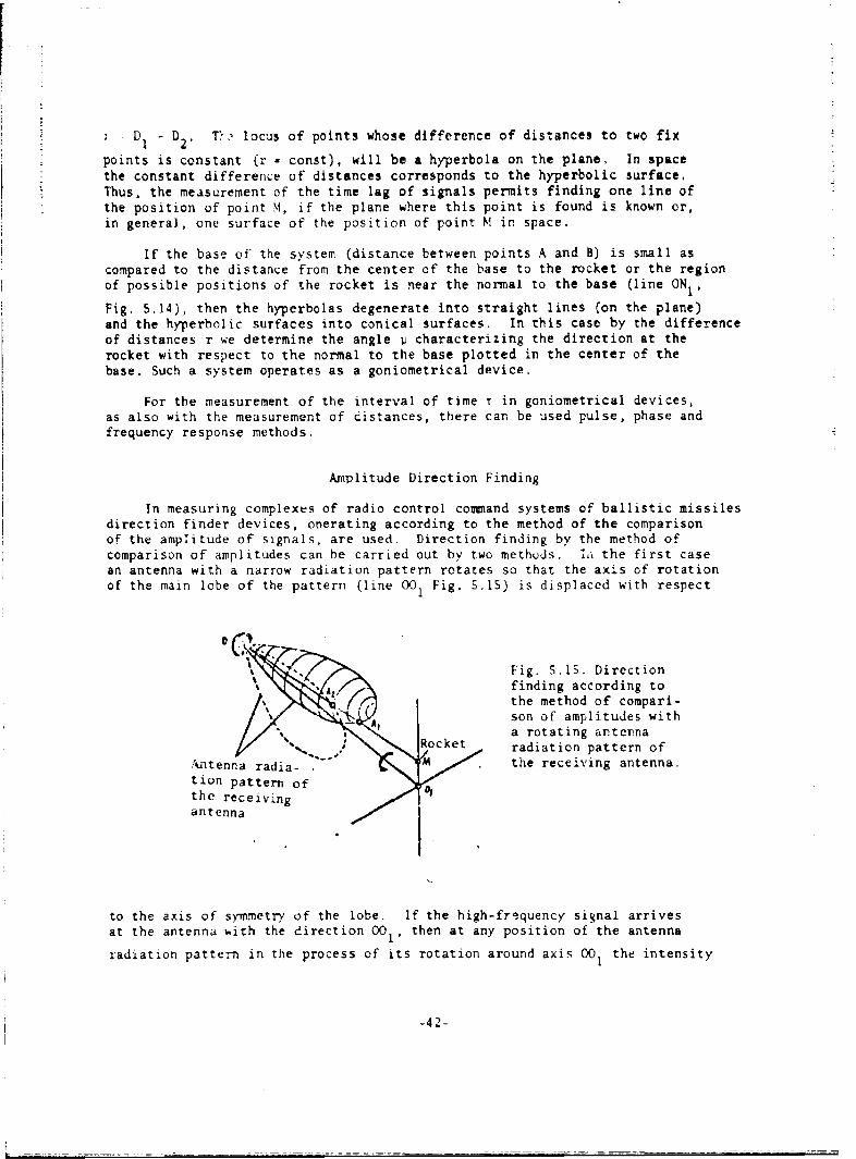
r
D! D TV locus of points whose difference of distances to two fix1 2
points is constant (r - const), will be a hyperbola on the plane, In spacethe constant difference of distances corresponds to the hyperbolic surface,Thus, the measurement of the time lag of signals permits finding one line ofthe position of point N1, if the plane where this point is found is known or,in general, one surface of the position of point M in space.
If the base of the system (distance between points A and B) is small ascompared to the distance from the center of the base to the rocket or the regionof possible positions of the rocket is near the normal to the base (line ON1,
Fig. 5.14), then the hyperbolas degenerate into straight lines (on the plane)and the hyperbolic surfaces into conical surfaces. In this case by the differenceof distances r we determine the angle ji characterizing the direction at therocket with respect to the normal to the base plotted in the center of thebase. Such a system operates as a goniometrical device.
For the measurement of the interval of time T in goniometrical devices,as also with the measurement of distances, there can be used pulse, phase andfrequency response methods.
Amplitude Direction Finding
In measuring complexes of radio control command systems of ballistic missilesdirection finder devices, ooerating according to the method of the comparisonof the amplitude of signals, are used. Direction finding by the method ofcomparison of amplitudes can be carried out by two methods. ia the first casean antenna with a narrow radiation pattern rotates so that the axis of rotationof the main lobe of the pattern (line 001 Fig. 5.15) is displaced with respect
Fig. S.15. Directionfinding according tothe method of compari-
A son of amplitudes witha rotating anternaRocket radiation pattern ofAnenaada ." M . the receiving antenna.
n t ion pattern of
the receivingantenna .
to the axis of symmetry of the lobe. If the high-frequency signal arrivesat the antenna with the direction 00l, then at any position of the antenna
radiation pattern in the process of its rotation around axis 001 the intensity
-42-

of the reception of the signal will be identical. If the signal arrives fromanother direction (for example, from the rocket being at point M), then depending
upon the position of the radiation pattern of the intensity of reception willbe changed: the greatest level of the signal will be proportional to the segmentOA and the least level (through a half-turn of the pattern) to segment OA2.
This will lead to modulation of the signal. The frequency of the modulationis equal to the frequency of rotation of the antenna radiation pattern (Fig.
Fig. 5.16. Voltages oscil-a7 lograms in circuits of the
direction finder with a
rotating antenna radiationpattern: a) high-frequencysignal; b) error signal;c) reference voltage.
b
c
5.16). and the initial phase of the envelope of the high-frequency signal dependson the position of the point M, i.e., on the direction of deviation of therocket from axis 001.
After amplification and detection in the receiving device of the high-frequency signal ec there is isolated the low-frequency voltage uc (Fig. S.16).
The amplitude and initial phase of this voltage characterize the deviationin space of direction OM from direction 001. In order to obtain information
on the mutual location in space of directions OM and 001, signal uc (error
signal) is compared with the reference voltage uo, the initial phase of whichis constant.
Using voltage uc as the control, it is possible to turn the antenna system
in such a manner that direction OM coincides with direction 001. Then the error
signal will become equal to zero. The position of axis 001 with respect to
the design of the antenna is known, and the movement of the antenna relativeto the initial position is accurately measured. Therefore, when u = 0 canbe determined the direction to the rocket (azimuth and elevation),c
In the second method of direction finding according to method of comparisonof amplitudes the antenna radiation pattern does not rotate, but there areused antennas creating four narrow-directional lobes (Fig. 5.17). Two lobes,partially overlapping one another, form an equisignal plane perpendicular tothe earth's surface; the other two lobes form an equisignal plane, perpendicular
* -43-

GCAPHIC NOT,.01 U KE
Fig. 5.17. Direction finding according tothe method of comparison of amplitudes witha fixed antenna radiation pattern.
to the first. The intersecing of these planes is an equisignal line for bothpairs of antennas. Comparing the signals of each pair of antennas with eachother, we obtain a voltage characterizing the attitude of direction-findingobject (rocket relative to the equisignal line. With the help of mismatchsignals it is possible to move the antenna to such a position when the equisignalline will be directed towards the rocket, which will allow producing measurementof azimuth and elevation.
By comparing both methods of amplitude direction finding, it is possibleto state the following. First, in direction finding with the help of a rotatingantenna radiation pattern there is required a greater time for the determinationof the angular coordinates. Results of the measurement can be obtained onlyafter, at least, one full turn of the antenna radiation pattern. In directionfinding by the second method the time necessary for measurements is many timesless, since the result can be obtained with the entering from the object ofone pulse. Therefore, similar systems are often called, monopulse, althoughthey can operate with continuous signals.
Secondly, the accuracy of measurement of angular coordinates in directionfinders with a rotating antenna radiation pattern is affected greater byinterferences. This is caused by the fact that with the formation of a mismatchsignal in these direction finders there are compared pulse amplitudes comingto the receiving antenna of the direction finder at different instants. Thelevel of interferences in the course of time is changed, they will affect amplitudesof comparable signals differently, and this will lead to the appearance ofspurious signal of mismatch and to errors in measurement. In direction findersoperating on the second method, pulse amplitudes coming from the object arecompared simultaneously. With the comparison (subtraction) of these pulsesinterferences are mutually compensated.
The accuracy of measurement with the help of amplitude direction findersdepends on the perfection of the measuring devices and the signal-to-noiseratio and is determined by the sharpness of the antenna radiation pattern ofantenna. With a large signal-to-noise ratio in direction finders with therotation of the antenna radiation pattern the error of measurement of the angles
-44-

can have a magnitude approximitely equal to -. 0.02,, where ; is the widthof the antenna radiation pattern on a level of half-power. In the directionfinder ith simultaneous comparison of signals it is possible to attain anaccuracy at which Ati - 0.00.- C! [30]. The angle -. depends on the effectivewavelength of the direction !'inder X0 and gcn,metric dimensions of the antenna.
For example, for an antTnna in the form of , parabolic mirror
0 r. 70 -I 'A1I
where 0? is measured in degrees; .2 is the diameter of the mirror in the sameunits as the wavelength. Consequently, with amplitude direction finding
1deg,, e: (O.35 - 1.-&) 11 do
The small magnitude of the error La can be attained (with not too large dimensionsof the antennas) only during operation of the direction finder at superhigh,requencies, Then, considering the possibility of unfavorable conditions ofthe reception of the signals, dimensions of the ancenna will be taken largerthan the last formula requires,
Determination of Directions by the lime Lag of Signals
The direction the rocket can be determined by the time lag of signalspassing the distance from the object to the two basic points (Fig. 5.14), Thistine z is equal to rc, where r D1 - 9, is the difference of distances between
the basic points and the object. For definitiveness we will assume that signalsare radiated from aboard the rocket and are received at two points on earth.kirectional properties of antennas wit- such a method of measurements are usedonly for the improveme.t of reception of signals (i,-crease in the signal-to-noise ratio) and for increasing the secrecy of operation of the system.
Let us find the coupling between time T and direction to the rocket inthe base - rocket plane. lhe angle - determnng this direction is measured,with respect to the normal to the base (Fig. 5.18), In real conditions of
#2A?
" -Fig. 5.18. Determination ofthe relationship between the
I length of the base, directionI to the rocket and time lag of
of the signals.
0
-45 -

rJ
operation of the goniometrical system the distance to the rocket D exceedsmany times the dimensions of the base d. In this case it is possible to assumethat lines AM, BM and OM are parallel to each other, If from point B we dropa perpendicular to line AM (point A1), then A1M = BM and segment AAI is equal
to r. Angle ABA1 is equal to angle w. Consequently, it is possible to write
I dii ' (sl12)
and
If line ONlo which is normal to the base, lies in the guidance plane of
the rocket, then deviations of the rocket from this line will be insignificant.Therefore the angle i.; will be small even with the largest permissible deviationof the rocket from the assigned trajectory. Then it is possible to takesin and write
(S.14)
or
d• . (5.15)
By measuring the time lag of signals T one can determine the direction to therocket (measure angle 1,). This principle can be assumed as a basis of differentsystems depending upon the method of measurement of time: pulse, phase andfrequency. Let us consider these methods of measurement of the quantity T.
1. Pulse method. In the case of the application of this method the signalshave the form of short-duration pulses. By measuring the time between thereception of pulses coming from the rocket at points A and B (Fig. 5.18), wedetermine the delay of signals T, These measurements are analogous to thosewhich are produced in pulse range finders, but the error in the measurementof angle depends not only on the accuracy of the measurement of time i butalso on value of base. If angle i, is small and it is possible to considersin = ., then from formula (S.15) we will obtain
Ai(5.1)
For example, if the accuracy of the measurement of the time interval is determinedby the error 6T, not greater than 0.03 1z, then so that the error of the measurementof angle Ai does not exceed 1 mrad, the system should have a base d of notless than 9 km. This makes the measuring complex bulky.
The merit of the pulse method of measurements is the fact that with itthere are no difficulties connected with the removal of ambiguity of reading.
-46-

2. Phase method. The measurement of time T in phase systems is producedby the difference of phases of two signals received in points A and B (Fig.5.18). As was shown in § 5.2, the relation between time t and difference ofphases 0 has the form:
2r
Considering this relation and carrying out the replacement X0 = cT0, we -illobtain from (5.15) for small angles of 1i
P .(5.17)
From the latter formula
all .4. (5.18)
High accuracy of measurement of angle 1 can be obtained by two means.The first means consists in the achievement of high accuracy of measurement
XOof phase shifts with a not very small ratio d In the second case we have
recourse to bases of large value as compared to the length of the operatingwave, which permits lowering the requirements, for the accuracy of measurementof difference of phaser. By certain means we find the application in practice.In command systems of radio control of rockets there can be selected radiowaves of very high carrier frequency f0 ' In this case the necessary accuracy
of measurements can be obtained owing to the selection of the small magnitudeX0
of the ratio -u. For example, if X0 = 3 cm, base d = 4 m, then even at an
error of measurements of difference of phases A = Ithe error of determinationof direction will not be larger than 1 mrad.
With the phase method of the measurement of angles, just as with the phasemethod of the measurement of distance, there is the question of the eliminationof ambiguity of readIfg. Actually, in the measurement of angleu is a magnitude
X 0equal to -Ui, there will occur measurement of the phase angle 0 for full cycle,
2r. To eliminate the ambiguity of reading there can be used methods discussedin §5.2 and also the method founded on the change in the length of the base,
Exact measurements are produced with base d, providing a small rati o".
i.e., high accuracy. To eliminate the ambiguity we pass to the operation witha smaller base d2 at which the sector of the single-valued reading has such
a magnitude that during flight in a powered-flight trajectory-the rocket cannotemerge outside its limits. With this there should be fulfilled the conditionthat the magnitude of the sector of the single-valued reading with accuratemeasurement be clearly larger than the error of measurement of angle p in workingwith a small base.
3. Frequency method. For realization of the frequency method of the
-47-

measurement of angles signals radiated by the flight equipment should be frequencNmodulated. Frequency modulation can be carried Cait in the same way as in thefrequency range finder (see S 5,2). In accordance with the earlier obtaineddependences (5,9) and (5.15), it is possible to write
rm".S.'t F (5.19)
We will assume that the error of measurement of the difference frequencyFp is equal to F and the modulation percentage a- 0.1 (see S.2), In this
case for achievement of the error of measurement of angle not larger than
1 mrad, it is necessary that -- be equal to or less than 2"10 " . Even for
a very high operating frequency f0 = 1010 ltz (N0 = 3 cm) in this case a base
ISO m wide is necessary.
Goniometrical Systems
According to data of literature there exists a large number of goniometricalsystems intended for the control of trajectories of rockets and artificialearth satellites in which measurements are produced by the phase method. Asa rule, these systems are designed in such a way that it is possible to determineboth azimuth and the angle of elevation.
Measurement of the phase shift between high-frequency oscillations isstrived for at a low frequency: the phase relationships between signals oflow frequency should accurately correspond to the difference of phases of high-frequency oscillations. The transition to low frequencies is connected withthe fact that technically it is considerably simpler to realize an accuratemeasuring device for the determinatio, of difference of phases at low frequenciesthan at superhigh freouencies utilized as operating (carrying) frequencies ofthe system. An -;ample of how these problems are solved can be the systemsdescribed in tech.iical literature.
For thc mcasurcmcnt of twc coordinates of a direction finding object(tzimuth , and elevation C) it is necessary to have two bases. In particular,these bases can be formed by three antennas. One anttnna is common for bothbases, and the other two antennas are located on mutually-perp-ndicular lines(Fig. 5.19). For simplicity of account let us assume distances AB1 and AB,
to be identical and equal to d. In the receiving-measuring device we determinethe phase shifts 1 and 2 between the high-frequency oscillations radiated
by the flight transmitter and received on earth. To determine we measure
the phase shift of signals between antennas A and B 1 and to determinc ,between antennas A and B.
The base of system d has small dimensions in comparison with the distanceto the direction finding object, and the.efore radio beams arriving from theobject to the antennas can be considered to be in parallel. Under these conditionswe can write
1rd
-48-

Rocket Fig. 5.19. Location of antenna in the
phase system of the measurement of azimuthand elevation.
V
a,,to
Between angle i and its projection on the horizontal plane -azimuth v there existsthe following coupling (Fig. S.3):
sil -a - sil ., Cos. (5.21)
where & is the angle of elevation. Thus
?I- , sill cos (5.22)
The base of the antennas AB2 is perpendicular to base AB1, and therefore
for phase angle 02 the following expression will be correct:
C S -C O S . ( 5 , 2 3 )
If one were to take the ratio of expressions (5.22) and (5.23), then we obtain
and, consequently, the azimuth can be determined by the formula
(5.24)
According to relations (5.22) and (5.23)
which makes it possible to determine the angle of elevation
-49-

Let us examine no6 how it is possible to carry out transition from thephase shift between high-frequency oscillations to the phase shift betweenlow frequency signals. The circuit should be built in such a way that additionalphase shifts in the equipment do not distort results of the measurements. Ablock diagram of the system in which there is realized one of the possiblesolutions of this problem is depicted in Fig. 5.20 [11, 29].
Anteria of te Aml~niA ofrle
Lis
A j,lifler of the Ao.I'p t- .F
Mixer or lot "7 iteeri. d*erde U Mixer of k"da ,o tF e i "
Fin 5.0. loc diarm fe h aprt si esrin hdfeeneo
If te phse s iftbetwer inl natna of Ra te frtadscncnnes srua oten fu te .lag ,'-andl u2 a h|upu ftehg
frequenc•amplifirs it.ispossibleto"write
a -, U cos •*i -(5.26)rj -de,+o
~8 1c (I -
(
Fig. 5.20 Block diagram of the apparatus measuring the difference ofphases between signals received on two spaced antennas.
If the phase shift between signals in antennas of the first and secondchanneqs is equal tocethen for the voltage uI and u2 at the output of the high
frequency amplifiers it is possible to write:
8l -- Cos, . (5.26)
a , =- V C o s ( , -- ) ,( 5 . 2 7 )
where the angle 0 is determined by formula (5.22) or (5.23), and w0 2rfowhere f 0 is the frequency of the signal of the flight transmitter. In themixer of the first channel thexe )ccurs the addition of signal u, and signalof frequency f , proceeding from the first heterodyne, The voltge of this

heterodyne can be britten in the folloing vav,
U,, * U, cos . (5.28)
In the mixer of the second channel there is added the signal u, with the signal
of the second heterodyne, and the voltage of this heterodyne is obtained fromthe voltage of the first heterodync by the increase in its frequency to a certainquant i ty
U ,.,
Consequently, for the output voltage of the second heterodyne it is possibleto write
u.,* U. u (v,, .i u-) I 1 ,.I 9,: (S.29)
As a result of the operation of the mixers, at their output with the helpof filters there are isolated signals of difference frequencies W0 - Wi and
U:0 - W P- l, so that for voltages u,,,1 and uc,, it is possible to write
,, ,, [(... ,,)t .I . (5.30)
These signals enter the basic amplifier of intermediate frequency, "he passbandof which permits without frequency and phase distortions to amplify the signaisin a frequency range from (fo - f, - F) to (fo - fr). Owing to the proximity
of frequency of voltages u.l and u there are for.efd beats and at the output
of the detector the voltage of thC 1c rc.z f. qu.ncy wi 1 b Sol at:ed
U f -t , c, (.I - , (5.32)
All high-frequency components after the detector are filtered.
In order with the help of the phasometer to determine quantity 0 at theinput of the phaseometer, besides voltage u , there should proceed the reference
voltage u0 of the frequency i2 = 2iF with the initial phase equal to 2 For
obtaining the voltage u0 the mixing of signals of the first and second heterodynes
is carried out. The voltage at the output of the mixer of the reference signalwill be characterized by the expression
. ,U. Cos (W: ___) (S. _33

By comparing formulas (5.32) and (5.33), we see that the difference in phasesof the two low-frequency voltages u¢ and u0 accurately corresponds to the difference
in phases between radio-frequency voltage in antennas of the first and secondchannels.
A large number of phasoi,,eteric gorniometrical systems operates on theseprinciples or ones close to them. In one of the systems (301 for accuratedetermining of angular coordinates a base with a length of 150 m at an operating
dfrequency of -100 MHz is used. This gives the ratio - equal 50. The error
of measurement of the difference of phases does not exceed r=and as a result
the accuracy angular measurements is characterized by an error approximately
of 20 . To remove ambiguity of reading there is provided an operation withshortened bases of the length 15 m. To improve conditions of the receptionsignals directional antennas are used each of which consists of 8-12 horizontaldipoles located at a distance of 1.5-2 ff from the ground. Installation ofreceiving antennas on the terrain is produced with the help of geodesic instrumentwith a precision of -6 mm. The frequency at which measurements of the differenceof phases are produced is equal 500 Hz.
1 5.4. Measurement of Speed
In systems of the radio control of rockets, for the formation of commandsignals it is necessary to have not only data on the position of the rocketin space, but also to know with high accuracy the magnitude and direction ofits speed. With the help of radiotechnical means first of all the radial speedis measured, i.e., the speed of the rocket along a line connecting the rocketand the control center. If the direction of the velocity vector does not coincidewith the rocket-control center line, then the angles t, j, and v will be changed.Therefore, in command systems of radio control it is necessity to measure notonly the radial but also the angular velocities.
Measurement of Radial Speed
In the preceding paziagraphs methods wctc dibcussed of the determaiationof spatial coordinates of the rocket. With continuous measurement of thesecoordinates it is possible to calculate the velocity component vectors. Asis known, to solve such a problem it is possible to compute the time derivativesfrom functions expressing the change in coordinates. The derivatives willbe equal to the components of speed in the direction of the cirresponding axes.For example, the value of radial speed b (component of speed in the directionof thz radius-vector of the polar system of coordinates) is found from theexpression
(5.34)
Mathematical operation of the determination of the derivative is accomplishedwith the help of a computer included in the equipment of the command guidance
-52-

system. With this, as a rule, the finding of the derivative from functionD(t) is replaced ty the determination of "he finite difference quotient ofthe function D(t-) - D(t for the small inte," of time to this interval
t, - t and expression (5.34) is replaced by ormu 1
6 : I , (1 0. (5.35)
lice D(t1 ) and D(t,) arc distances between thv point of measurement and rocket
at instants t1 and t. With such (indirect) method of the determination of
speed, to achieve high accuracy it is necessary to carry out averaging of theresults of measurements, which leads to a delay in the obtaining of data necessaryfor operation of the control system and in the end negatively affects the accuracyof control. Therefore, in command guidcutce systems of rockets direct methodsof the measurement of radial speed, founded on use of he Doppler effect, areused.
The Doppler effect consists in the fact that the frequency of oscillationsreceived by the receiver in the case when the receiver and radiator move relativeto each other differs from the frequency of oscillations received by the reLeiverin the absence of movement. With the approach of the source of oscillationswith the receiver there occurs an increase in frequency and in the departureof it, a lowering.
The reason for this phenomenon is simple to explain by examining the radiationand reception of harmonic oscillations. Let us assume that at a certain instantat the point of reception B the phase of harmonic oscillations radiated bythe transmitter located at point A corresponds to maximum (Fig. 5.21). If the
7
At A Al
Fig. 5.21. Oscillograms clarifying the Dopplereffect.
receiver and transmitter do not move relative to each other, then upon the1expiration of time To (where f0 is the frequency of the radiated 3cillations)0
the phase cf oscillations at point B will again correspond to the maximum.In this case the frequency of the received oscillations will be equal to thefrequency of the radiated oscillations.
If the receiver will start to move with respect to the transmitter (for
-53-

example, departing from it), then the time ot arrival to it of the secondmaximum will be increased as compared to the preceding case by ,T. The timeAT is conditioned by the fact that the electromagnetic wave should pass theadditional distance E at which the receiver moves during T0 + AT. It is obvious
that t. (TO + AT)V where V is dir.cret. ?long the transmitter-receiver line,p p
i.e., V constitutes the radial speed.p
As a result of movement of the receiver radio waves at point B will bereceived not as oscillations, with the period TO, but as oscillations with the
period T I equal to T a TO + LT. The quantity AT will consist of AT = -, where
c is the speed of propagation of electromagnetic oscillations. Considering thatX- (T + AT)V, it is possible to write
0 p
(5.36)
Trning to the frequency of oscillations, we will obtain that the frequencyf of the signal, which will be received by the receiver in its travel with
respect to the transmitter with speed Vp, will be equal top2
The minus sign corresponds to the departure of the receiver from the transmitterand the plus sign, to their approach.
From expression (S.37) it is easy to determine the difference frequency(Doppler frequency) F :
tf -. (5.38)
Thus if one were to measure the frequency F., then one can determine the speed
V of the travel of the receiver and transmitter relative to each other inpa radial direction:
V,- TPA. F, (5.39)
Technically for an accurate measurement of the difference frequency F~.
it should have a sufficiently large magnitude (hundreds and thousands of Hz).
lf the measuring equipment of speed V and the measuring equipmentP
of distance 0 are at the same point, then V = D.P
-54-

Thereofoie, the measuremnint of the speed of the rocket with the help of theDcppler effect is carried out or radio waves of the ultra-high frequency range,To measure the frequency I- it i- necessary that at the point of measurement
the frequency of oscillations ra iiated by the transmitter be known with highaccuracy. An analogous rcquiremc: - as is knowni (-ec § 5 2, appears in systemsof measurement of distance, and its satisfaction in the measurement of speedcan be carried out by the same methods as in range finders, by the installationon board the rocket arid :It the ground station of two high-stability generatorsor by means of re-emission of signals.
Let us examine how great the relative stability of generators should beif operation of the system is carried out by the first method, The instabilityof the frequency of generators installed at control center and en the rockotwill lead to the appearance of a false difference of frequencies t.F, whichwill cause the error AV in the measurement of speed. According to the formula
(5.38) it is possible to write
F, 4 S I 'V 4 J p- (S.40)-I, e-" - ( .4
From the relation (5.40) it follows that
, .... t (5.41)
The latter expression permits determining the permissible magnitude relative
detuning of the gent ators r If one were to assume that the error of measurementV
of the speed caused by instability of generators should not exceed 0.1 m/s,
then by the formula (5.41) we will obtain F 1010. This relative frequency
fo0drift of ground and flight generators should not be exceeded during the wholetime of operation of t~e measuring system, which is very difficult to fulfill.Of all the known devices only atomic and molecular generators have such highstability of frequency. The application of generators in control systems isconsidered very promising [19].
If the system of measurement of speed uses signals re-emitted from therocket, the requirements for stability of frequency are reduced. In thesesystems the Doppler effect appears twice - during reception of the signal onthe rocket and during its reception in the control center, The expressionconnecting the radial speed of the rocket Vp and difference frequency F in
the system with re-emission will be written in the following way:
.... --. (S ,42)
For the separation of direct and re-emitted signals in systems with activeresponse we operate on two frequencies. One frequency is of the transmitterof ground station (in the control center) and the other -the flight Tesponder(radio relayer).
-55 -

The accur~cv of meusurement of radial .petd in Doppler systems dependson the accuracy of the measurement of difference frequency and in systems with
rele.ying practically does not depend on the stability of hMghofrequency generators.9 10
of tht rocket 5-7 km/s, the difference frequency attains a magnitude of hundreds
of klz. In order that the error of measuroment cf speed does not exceed thedesired value, the measurement of this frequency must be produced with an error
measured by Hz units.
The difference frequency can be measured by determining the number of
periods of oscillation of this frequency for a fixed interval of time. Forthe convenience of measurement sinusoidal oscillations exceed in pulses similarto that as was described ini 5.2 (Fig. 5.11). The number of pulses in limitsof the fixed interval of time will be proportional to the mean value of frequencyF during the counting time. The output signal of the pulse counter can be
represented in binary code and introduced into the computer of the commandsystem of radio control.
Meaburement of Angular Velocity
In radio control command systems the measurement of radial speed of therocket is supplemented by a measurement of the angular velocity of rotationof line of sight of the rocket from the control center. We measure the angularvelocity of rotation of line of signt in a vertical plane t and angularvelocityof ruation of the projection of line of signt on the horizontal plane v.
Measurement of angular velocities ' and p i :oduccd by thc indirectmoth-d - tim- derivat;ve of the anuls% of ,.nd are foud. In practice weuse finite increment! and calculate, for example -, by the formula
' t -'(5,43)
where v(tl) and vkt) are values of angle v at instants t1 and t2 . Angles
v and E for the calculaticz of angular velocities are determined with the helpof the same systems as those which were described in S 5.3. HOwevey, for obtainingthe necessary accuracy of measurement of angular velocities these systems shouldhave different characteristics than during the measurement of angles.
With amplitude direction finding accurate measurement of the angular velocityof rotation of the line of signt is possible if the antennas have an extremelysharp antenna radiation patter. This requires the application of antennaswith large dimensions. Even for waves of the centimeter range the antennashould have dimensions of several meters. In technical literature devotedto contemporary control systems of ballistic missiles there is not encounteredindications of the application of amplitude direction finders for the determinationof angular velocities.
Measurement of angular velocity of rotation of the line of sight v (or F)
can be carried out by the phase method. For simplification we will assumethat the angle of elevation C a 0 and angle v is small, so that it is possibleto assume sin v v . Under these conditions instead of formula (5.22) wewill write
-Sb-

LNu
whence
(5.44)
The relation between errors of measurement Lv and A has the form
d : (2 .. 5 ) 10 1), (5 .4 5 )
If one weye to assume that the angular velocity < is measured with an
error not exceeding the magnitude of the order of 10-6 rad/s, and radiotechnicaldevices determined the speed of the change in difference of phases €I with
an error at several degrees per second, then it is possible by formula (5.45)to cbtain the necessary length of the base of the system d:
C
Thus the phase system operating on radio waves of the three-centimeter range,for achievement of the necessary accuracy of measurement of angular velocities,should have a base with the length of 60-150 m. This value is considerablylarger than the length of the base with measurement of angular coordinatesof the rocket (see § 5.3). However, the creation of the phase system with abase at 60-150 m does not now present principal technical difficulties.
The pulse method of measurement of angular velocities of the line oi sightconsists in the following. At 0, instead of formula (5.14), it is possibleto write
"j ?a
It is assumed that the angle v is small. On the basis of the last expression
'# (5.46)
whence
A (5.47)
Let us assume that the measurement of At is fulfilled with an error of0.1 Us/s. On the basis of this value and the requirement that the error of
measurement v does not exceed 2.10 -6 rad/s, it is possible to calculate byformula (5.47) the length of the base of the pulse system. It will be equalto d a 1500 km. The system of measurement is obtained bulky.
Measurement of quantities ; and t can be fulfilled also by the frequencymethod. If one were to corsider C a 0, then formula (5.19) can be replacedby the following:
-57-

From this formula there follows
~'t'" (5.,48)
Hence we find
A, ' (5,49)
In order that it wi.s possible confidently to reveal during the short intervalof time (for providing the required high-speed operation of the control system)the change in difference frequency F . this frequency should be changed with
sufficiently great speed. Considering that the frequency shift F is multiple
to the frequency of modulation F (see 1 5.2). we will assume that AF should
be numerically equal approximately to FM fl:/s. Taking into account this condition,
from the relation (5.49) one can determine that the base of the measuring systemwith frequency modulation should be equal to 100-200 km.
From a comparison of the different methods of measurement of angular velocityof rotation of the line of sighting advantages of phase systems are seen. Suchsystems at superhigh frequencies permit obtaining great accuracy of measurementof angular ve.ocity with not too great a length of the base of the antennas.
System of Mcasurement of Radial Velocity
Let us examine in the form of an example the functional diagram of theequipment for measurement of radial velocity represented in Fig. S.22 [4).The equipment is included in flying range control of ballistic missiles andinclude a ground station and flight responder. Operation of the system is
totr O--- -. ,r" ..... j L r~j J LI ......
1m*' Afoe;r.-Arterfl
t I of,
- Orem%1 or, Gr . And I I g"
of oorm ,u1j a lalon re oPonder
Fig. S, _,L Block diagra.in of the apparatus measuring
the radial velocity of the rocket.
FTD-N1 -24 -304 -o7 -58-

The high-stability master oscillator with a crystal stabilizer producesoscillations of the carrier frequency f0 The transmitter of the ground station
radiates these oscillations. Owing to the motion of the rocket the frequencyof oscillations fI received on the rocket will be less than the frequency of
the interrogation signal.
where V is the radial velocity of the rocket, and c is propagation velocitypof the radio waves.
The received signal is subjected to frequency multiplication. Frequencymultiplication serves for the separation of interrogation and return signals,otherwise the signal coming from the rocket is difficult to separate againstthe background of the powerful radiation of the transmitter. T'2 frequencyof the signal can be multiplied by the number n, whole or fractional. Afterthe multiplier we obtain oscillations with a frequency
hui " , " i.(' ""- (5.51)
which are transmitted to earth.
The ground receiver separates the signal by the frequency f3, which differsdue to the motion of the rocket from the value f2
C5.52)
VThe ratio -2- is many times less than unity. Therefore it is possible to considerc
V"c ' C - . ( 5 .5 3 )
Then the frequency of signal f3 will be equal to
This signal is fed to the mixer together with the, multiplied frequency byn of the master oscillator f0 oscillations. The difference frequency of the
signal obtained at the output of the mixer will be equal
1.VP. 2nf. -2-. (s.ss)
The frequency Doppler meter F. is fulfilled by the following functions. .4If the frequency FA has a value corresponding to the calculated speed of the -AIFTD-MT-24-304-67 -59-
_______

rocket, the meter should issue a signal for the formation of a single command.There are formed two single commands, the preliminary and basic. Therefore,the meter should nave tuning for two values of the difference frequency.
During the flight of the rocket the frequency FA, together with the speedof the rocket, cortiruously increases. The first signal of the frequency meter
is formed when the speed of the rocket reaches the value at which there shouldbe issued the preliminary command. The second signal of the meter correspondsto the basic command.
The station of the measurement of velocity, using the Doppler effect,determines the component of velocity of the rocket directed along the lineof propagation of the radio wave. If it is necessary to measure the full speedof the rocket V, then ground the station is located in the guiding plane atsuch a point that on the segment of the measurement of velocity the trajectoryof the rocket will coincide as fully as possible with the line AB (Fig. 5.23).-In this case the radial velocity of the rocket V with sufficient accuracy ..
be equal to the full speed V. -
~Sarnert TSv+!oolt. , Si~c
/ / SIWmrd
0 offr n!c
-i J t cr.c.c
t
A
ta'ior. of ir.6 ;Cnt cfMosereT*ht of 1A-r of
Vol C.i 1.' tr.o rooket
Fig. 5.23. Distribution of the stationof measurement of velocity.
if-
FTD-MI-24-304-t7 -60-