jin li - microsoft.com filejin li sharp labs. of america 5750 nw p aci c rim blvd., camas, w a 98607...
TRANSCRIPT

Hybrid Wavelet-Fractal Image Compression
Based on A Rate-Distortion Criterion
Jin Li
Sharp Labs. of America
5750 NW Paci�c Rim Blvd., Camas, WA 98607
C.-C. Jay Kuo
Integrated Media Systems Center and Department of Electrical Engineering-Systems
University of Southern California, Los Angeles, California 90089-2564
ABSTRACT
A new hybrid wavelet-fractal coder (WFC) for image compression is proposed in this research. We show thatthe application of contractive mapping for interscale wavelet prediction in the wavelet domain o�ers bit rate savingsin some regions. The prediction residue is then quantized and encoded by traditional wavelet coders. WFC allowsthe exibility to choose either direct coding of wavelet coe�cients or fractal prediction followed by residual codingto achieve a better rate-distortion (R-D) performance. A criterion of low complexity is derived to evaluate the R-De�ciency of fractal prediction. The superior performance of WFC is demonstrated with extensive experimentalresults.
Keywords: wavelet-fractal coder, image coding, fractal compression, wavelet compression.
1 INTRODUCTION
Research on theory and applications of fractals has been performed for more than thirty years. Pentland [12],among many others, showed that quite a few natural physical processes generated fractal-like surfaces and whenthe 3-D fractal surface projected to a plane, the resulting 2-D image had a self-similar property which characterizeda fractal image. The application of the fractal (or self-similar) concept to practical image compression was �rstdemonstrated by Jacquin [8], who proposed a block-based fractal coder. More improvements have been performedby many researchers at a later stage [6], [7].
Fractal compression is however distinctive from conventional transform-based coding methods in several aspects.First, it uses parameters of the contractive mapping [8] to encode an image rather than a direct coding of itscontent. Second, unlike the invertible transform used in transform-based coders, contractive mapping is an irreversibleprocedure. Third, quantization of contractive mapping parameters is not the main source of distortion. Compressionartifact is primarily caused by the process of contractive mapping. As a result, the bit rate and image qualitycontrol for the fractal coder is di�cult to perform. In spite of all achievements in fractal theory and fractal coderimplementations, the rate-distortion (R-D) performance of fractal coders is disappointing. They can hardly competewith the state-of-art wavelet coders such as the embedded zerotree wavelet coder (EZW) proposed by Shapiro [14]and the layered zero coder (LZC) proposed by Taubman and Zakhor [15].

The relationship between the fractal and the transform-based coders has been recently unveiled by researches [2],[4]. It can be shown that contractive mapping actually explores redundancy between di�erent image resolutions, andcan be viewed as an interscale prediction in the wavelet domain. Thus, there should be a way to combine fractal andwavelet coding ideas for a better compression method. Rinaldo and Calvagno [13] proposed a predictive pyramidcoder (PPC) by exploring the interscale redundancy. PPC performs a block-based prediction which predicts �nerscale wavelet coe�cients from those of coarser scales. The prediction of PPC is independent for each scale anddirectional subband, and the block size can be adjusted. It turns out that PPC bears little resemblance to thecontractive mapping de�ned in traditional fractal coders. Also, its coding e�ciency is still not as good as EZW andLZC (see Table 2 in Section 5).
In this paper, we attempt to shed more light on the relationship between contractive mapping and wavelet coding.Following the pioneering work in [2], [4], a more complete framework for fractal prediction in the wavelet domainwill be developed. It includes three components: (1) the contractive operator that provides prediction across waveletscales, (2) the scaling operator that shrinks prediction coe�cients, and (3) the isometrical transformation whichshu�es pixels within and across subbands. We will then integrate the wavelet domain contractive mapping withwavelet coders which leads to a new hybrid wavelet-fractal coder (WFC) with a superior R-D performance. Unlikeconventional fractal coders where the whole image is encoded by fractal alone, we only apply fractal prediction to aselected part of the image whenever it is more e�cient. To be more precise, an adaptive rule is developed to evaluatethe perspective rate saving achieved by fractal prediction, which is then compared with the overhead bits requiredby prediction. Fractal prediction is only adopted when the rate saving is more than the overhead. Finally, bothunpredicted wavelet coe�cients and fractal prediction residue are quantized and entropy encoded by state-of-the-artwavelet coders. Experimental results show that fractal prediction is able to reduce the coding rate in a certain bitconsuming area such as the texture region and improves the overall R-D performance of the coder.
The paper is organized as follows. We describe the implementation of contractive mapping in the wavelet domainin Section 2. Algorithmic details of WFC are presented in Section 3. The issue of estimating perspective rate savingbased on a model-based R-D criterion is investigated in Section 4. Extensive experimental results are provided tocompare the performance of WFC with various state-of-the-art fractal and wavelet coders in Section 5. Concludingremarks are given in Section 6.
2 INTERSCALE WAVELET PREDICTION VIA CONTRACTIVE MAPPING
2.1 Contractive Mapping in the Space Domain
The conventional fractal coder operating on spatial domain blocks is brie y reviewed below. Let us partition theimage f into a set of non-overlapping square range blocks frj; j = 1; � � � ; NRg of size KR �KR. That is,
NR[j=1
rj = f ; ri \ rj = ;; for i 6= j; (1)
rj = f(x; y) j rx �KR=2 � x < rx +KR=2; ry �KR=2 � y < ry +KR=2g: (2)
The range block has to be matched with a domain block of size KD �KD:
dk = f(x; y) j dx �KD=2 � x < dx +KD=2; dy �KD=2 � y < dy +KD=2g: (3)
Centers of the range and domain blocks, i.e. (rx; ry) and (dx; dy), are used to denote their positions. Usually, thesize of the domain block is twice of that of the range block KD = 2 �KR. All domain blocks constitute a domainpool
D = fdk; k = 1; � � � ; NDg:During the matching process, the domain block dk is averaged and subsampled from size KD �KD down to sizeKR �KR, and followed by isometrical transformation, contrast scaling and o�set operations. Mathematically, theprocess can be written as
r̂j = �j(dk) = �j�j(Sj(dk)) + oj ; (4)

Domain block
Range block
Fractal match
(a)
Domainblock
Domainblockposition
Range block
Range block positionFractal prediction
( not in use )Scale 1 domain block
(b)
Figure 1: Contractive mapping in (a) the spatial domain, (b) the wavelet domain
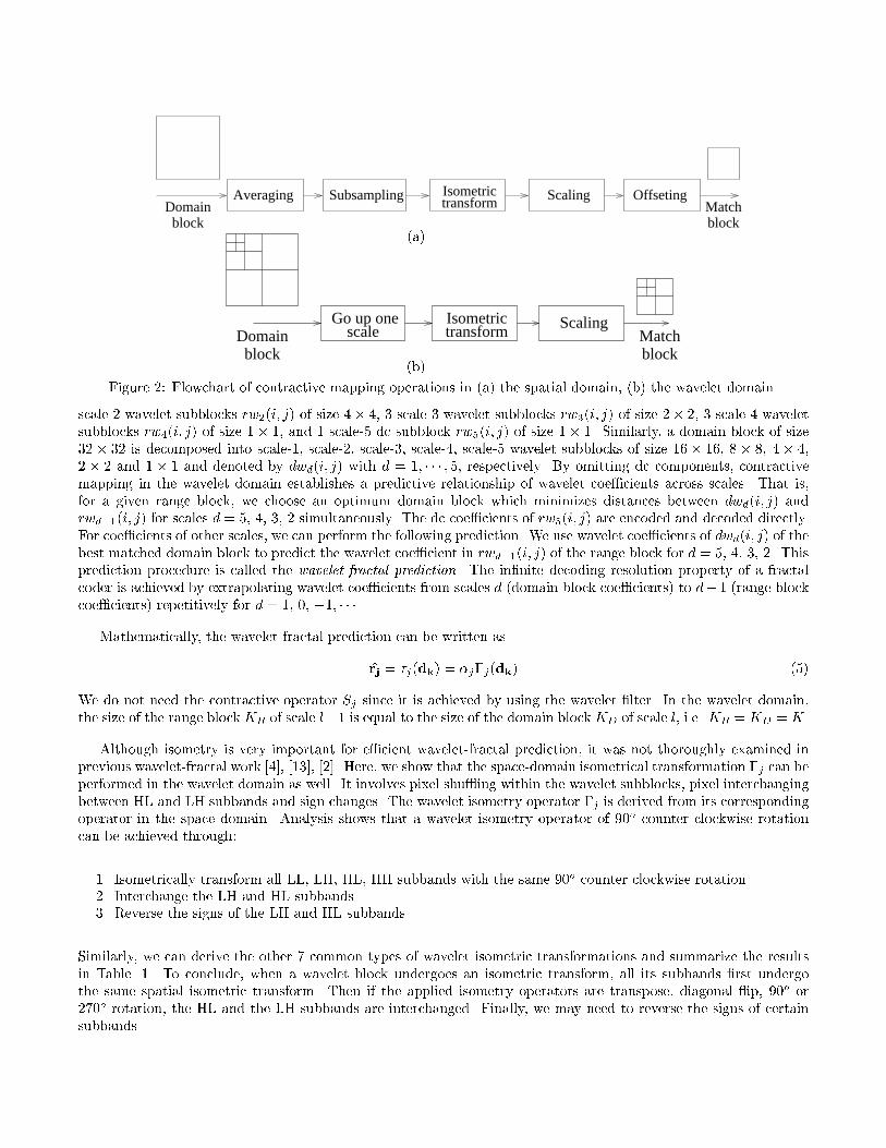
where Sj , �j , �j and oj represent the spatial contraction, isometrical transformation, contrast scaling and luminanceo�set, respectively. Isometrical transformation �j includes identity, horizontal and vertical ip, diagonal re ectionalong the �rst axis (transpose) and the second axis (diagonal ip), and 90o, 180o, and 270o rotations [8]. Fractalmatching in the space domain is depicted in Fig. 1(a), and the corresponding operating chain of (4) is shown inFig. 2(a). Due to the use of the spatial contraction operator Sj , this search process is also known as contractive
mapping.
For each range block rj, it requires a high computational complexity to search the best matching domain block dk
for its position (dx; dy), isometrical transformation �j , scaling parameter �j and o�set parameter oj . To reduce thecomplexity, it is possible to search within a subset Dj of the entire domain pool for locality control and/or classi�edblock matching. Once the range-domain match pair r̂j = �j(dk) is determined, fractal decoding can be carried outiteratively.
2.2 Contractive Mapping in the Wavelet Domain
Fractal signals possess a self-similar property across scales while the wavelet transform provides an e�cientmultiresolution representation of signals. It is thus interesting to investigate the fractal structure in the waveletdomain. Let us perform the Haar wavelet transform on both range and domain blocks. Then, the chain of spatialcontractive mapping operations shown in Fig. 2(a) can be converted to the chain of wavelet contractive mappingoperations shown in Fig. 2(b). The averaging and subsampling operation Sj is equivalent to moving up the domainblock by one scale in the wavelet domain, since the Haar transform is exactly the same as the combined averagingand subsampling operations. The isometrical transformation operator �j corresponds to a pixel shu�ing operationwhich may involve additional sign changes and inter-subband coe�cient exchanges. The contrast scaling factor �jis reduced by half because of the normalization process in the wavelet transform, and the o�set oj is related only tothe di�erence between the dc components of the range and the domain blocks.
Each domain or range block in the space domain is now decomposed into several subblocks across scales anddirectional subbands in the wavelet domain. For typical test images of size 512�512 in our experiments, we considerrange and domain blocks of sizes 16 � 16 and 32 � 32, respectively. After performing a 5-level pyramid waveletdecomposition, A range block of size 16� 16 is decomposed into 3 scale-1 wavelet subblocks rw1(i; j) of size 8� 8, 3
IsometrictransformSubsamplingAveraging
Domainblock
Matchblock
Scaling Offseting
(a)
Domainblock
Go up onescale transform
Isometric Scaling
blockMatch
(b)
Figure 2: Flowchart of contractive mapping operations in (a) the spatial domain, (b) the wavelet domain
scale-2 wavelet subblocks rw2(i; j) of size 4� 4, 3 scale-3 wavelet subblocks rw3(i; j) of size 2� 2, 3 scale-4 waveletsubblocks rw4(i; j) of size 1� 1, and 1 scale-5 dc subblock rw5(i; j) of size 1� 1. Similarly, a domain block of size32 � 32 is decomposed into scale-1, scale-2, scale-3, scale-4, scale-5 wavelet subblocks of size 16� 16, 8 � 8, 4 � 4,2 � 2 and 1 � 1 and denoted by dwd(i; j) with d = 1; � � � ; 5, respectively. By omitting dc components, contractivemapping in the wavelet domain establishes a predictive relationship of wavelet coe�cients across scales. That is,for a given range block, we choose an optimum domain block which minimizes distances between dwd(i; j) andrwd�1(i; j) for scales d = 5; 4; 3; 2 simultaneously. The dc coe�cients of rw5(i; j) are encoded and decoded directly.For coe�cients of other scales, we can perform the following prediction. We use wavelet coe�cients of dwd(i; j) of thebest matched domain block to predict the wavelet coe�cient in rwd�1(i; j) of the range block for d = 5; 4; 3; 2. Thisprediction procedure is called the wavelet-fractal prediction. The in�nite decoding resolution property of a fractalcoder is achieved by extrapolating wavelet coe�cients from scales d (domain block coe�cients) to d� 1 (range blockcoe�cients) repetitively for d = 1; 0; �1; � � �.
Mathematically, the wavelet-fractal prediction can be written as
r̂j = �j(dk) = �j�j(dk) (5)
We do not need the contractive operator Sj since it is achieved by using the wavelet �lter. In the wavelet domain,the size of the range block KR of scale l�1 is equal to the size of the domain block KD of scale l, i.e. KR = KD = K.
Although isometry is very important for e�cient wavelet-fractal prediction, it was not thoroughly examined inprevious wavelet-fractal work [4], [13], [2]. Here, we show that the space-domain isometrical transformation �j can beperformed in the wavelet domain as well. It involves pixel shu�ing within the wavelet subblocks, pixel interchangingbetween HL and LH subbands and sign changes. The wavelet isometry operator �j is derived from its correspondingoperator in the space domain. Analysis shows that a wavelet isometry operator of 90o counter clockwise rotationcan be achieved through:
1. Isometrically transform all LL, LH, HL, HH subbands with the same 90o counter clockwise rotation.2. Interchange the LH and HL subbands.3. Reverse the signs of the LH and HL subbands.
Similarly, we can derive the other 7 common types of wavelet isometric transformations and summarize the resultsin Table. 1. To conclude, when a wavelet block undergoes an isometric transform, all its subbands �rst undergothe same spatial isometric transform. Then if the applied isometry operators are transpose, diagonal ip, 90o or270o rotation, the HL and the LH subbands are interchanged. Finally, we may need to reverse the signs of certainsubbands.

Isometry Spatial Wavelet Domainr(i; j) wlh
l (i; j) whll (i; j) whh
l (i; j)
Identity d(i; j) wlhl+1(i; j) whl
l+1(i; j) whhl+1(i; j)
Flip up-down d(�i; j) wlhl+1(�i; j) �whl
l+1(�i; j) �whhl+1(�i; j)
Flip left-right d(i;�j) �wlhl+1(i;�j) whl
l+1(i;�j) �whhl+1(i;�j)
Transpose d(j; i) whll+1(j; i) wlh
l+1(j; i) whhl+1(j; i)
Diagonal ip d(�j;�i) �whll+1(�j;�i) �wlh
l+1(�j;�i) whhl+1(�j;�i)
90o rotation d(j;�i) �whll+1(j;�i) wlh
l+1(j;�i) �whhl+1(j;�i)
180o rotation d(�i;�j) �wlhl+1(�i;�j) �whl
l+1(�i;�j) whhl+1(�i;�j)
270o rotation d(�j; i) whll+1(�j; i) �wlh
l+1(�j; i) �whhl+1(�j; i)
Table 1: Correspondence of the isometry operator in the spatial and wavelet domains.
biorthogonal wavelet transformDecompose the image by 9-7
contractive mappingEvaluate the fractal
d-1 coeff. from scale dFractal predict scale
d-1 prediction residueEncode scale
d=d-1
d=0?
End
contractive mappingFind the fractal
Start Encode scale dwavelet coefficient
Coding
Decomposition
Fractal search & evaluation
Figure 3: Framework of the fractal wavelet coder
The wavelet contractive mapping relation is derived through the Haar wavelet. Nevertheless, we extend it toother wavelet basis. In fact, the spatial fractal matching relation (4) is nothing more than an assumption that in thespace domain, the range block resembles the contractive mapping of the domain block. Extending this assumptionto its counterpart in the wavelet domain, we assume that the wavelet coe�cients of coarse scale can be predicted bya wavelet contractive mapping of the �ne scale. The wavelet contractive mapping involves the speci�cation of therange-domain pair r̂j = �j(dk), the wavelet isometry operator �j , and the scaling operator �j , as shown (5). Thisassumption, which does not constrain the wavelet basis to be haar, is the core of wavelet-fractal prediction.
There are several variations in implementing the prediction between wavelet subbands. One is to perform scale-dependent prediction. That is, we determine the best range-domain block pair for every two consecutive scales.Another possibility is to allow scale and directional-dependent prediction as done in PPC [13] to reduce the predictionerror. However, they are not as e�cient as the one described above in optimizing the rate-distortion performance.
3 WAVELET-FRACTAL CODER (WFC)
A new hybrid image coder called the wavelet-fractal coder is proposed in this section. Generally speaking, we�rst transform an image from the space domain to the wavelet domain. Then, wavelet coe�cients are either encodeddirectly or predicted from coe�cients from the previous scale via contractive mapping. For the latter case, bothcontractive mapping parameters and prediction residuals are encoded. The owchart of the proposed wavelet-fractalcoder (WFC) is depicted in Fig. 3. Detailed implementations are described below. Without loss of generality, weconsider the case that the image to be compressed is of size 512� 512 in the following discussion.
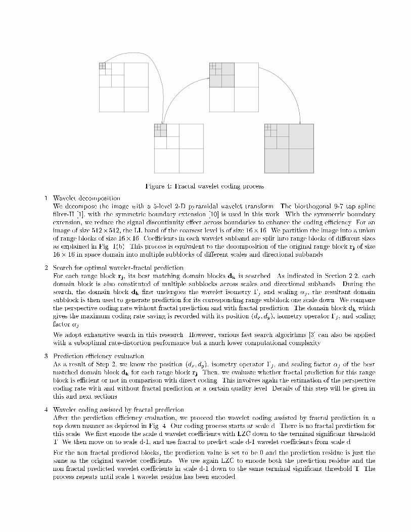
Figure 4: Fractal wavelet coding process
1. Wavelet decompositionWe decompose the image with a 5-level 2-D pyramidal wavelet transform. The biorthogonal 9-7 tap spline�lter-II [1], with the symmetric boundary extension [10] is used in this work. With the symmetric boundaryextension, we reduce the signal discontinuity e�ect across boundaries to enhance the coding e�ciency. For animage of size 512�512, the LL band of the coarsest level is of size 16�16. We partition the image into a unionof range blocks of size 16�16. Coe�cients in each wavelet subband are split into range blocks of di�erent sizesas explained in Fig. 1(b). This process is equivalent to the decomposition of the original range block rj of size16� 16 in space domain into multiple subblocks of di�erent scales and directional subbands.
2. Search for optimal wavelet-fractal predictionFor each range block rj, its best matching domain blocks dk is searched. As indicated in Section 2.2, eachdomain block is also constituted of multiple subblocks across scales and directional subbands. During thesearch, the domain block dk �rst undergoes the wavelet isometry �j and scaling �j , the resultant domainsubblock is then used to generate prediction for its corresponding range subblock one scale down. We comparethe perspective coding rate without fractal prediction and with fractal prediction. The domain block dk whichgives the maximum coding rate saving is recorded with its position (dx; dy), isometry operator �j , and scalingfactor �j .
We adopt exhaustive search in this research. However, various fast search algorithms [3] can also be appliedwith a suboptimal rate-distortion performance but a much lower computational complexity.
3. Prediction e�ciency evaluationAs a result of Step 2, we know the position (dx; dy), isometry operator �j , and scaling factor �j of the bestmatched domain block dk for each range block rj. Then, we evaluate whether fractal prediction for this rangeblock is e�cient or not in comparison with direct coding. This involves again the estimation of the perspectivecoding rate with and without fractal prediction at a certain quality level. Details of this step will be given inthis and next sections.
4. Wavelet coding assisted by fractal predictionAfter the prediction e�ciency evaluation, we proceed the wavelet coding assisted by fractal prediction in atop-down manner as depicted in Fig. 4. Our coding process starts at scale d. There is no fractal prediction forthis scale. We �rst encode the scale d wavelet coe�cients with LZC down to the terminal signi�cant thresholdT. We then move on to scale d-1, and use fractal to predict scale d-1 wavelet coe�cients from scale d.
For the non fractal predicted blocks, the prediction value is set to be 0 and the prediction residue is just thesame as the original wavelet coe�cients. We use again LZC to encode both the prediction residue and thenon fractal predicted wavelet coe�cients in scale d-1 down to the same terminal signi�cant threshold T. Theprocess repeats until scale 1 wavelet residue has been encoded.
0 1 2 3 4 5 6 7 80
5
10
15
20
25
30
35
40
45
50
beta = 2.0160
Rate(bpp)
Dis
tort
ion(
dB)
(a)
0 1 2 3 4 5 6 7 80
5
10
15
20
25
30
35
40
45
beta = 1.9248
Rate(bpp)
Dis
tort
ion(
dB)
(b)
0 1 2 3 4 5 6 7 80
5
10
15
20
25
30
35
40
45
beta = 1.8694
Rate(bpp)
Dis
tort
ion(
dB)
(c)
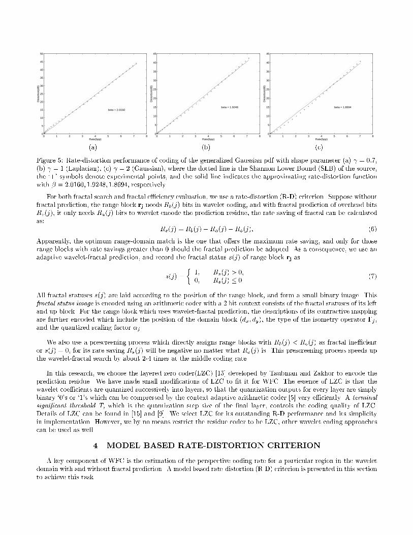
Figure 5: Rate-distortion performance of coding of the generalized Gaussian pdf with shape parameter (a) = 0:7,(b) = 1 (Laplacian), (c) = 2 (Gaussian), where the dotted line is the Shannon Lower Bound (SLB) of the source,the `+' symbols denote experimental points, and the solid line indicates the approximating rate-distortion functionwith � = 2:0160; 1:9248; 1:8694, respectively.
For both fractal search and fractal e�ciency evaluation, we use a rate-distortion (R-D) criterion. Suppose withoutfractal prediction, the range block rj needs Rb(j) bits in wavelet coding, and with fractal prediction of overhead bitsRo(j), it only needs Ra(j) bits to wavelet encode the prediction residue, the rate saving of fractal can be calculatedas:
Rs(j) = Rb(j)�Ra(j)�Ro(j); (6)
Apparently, the optimum range-domain match is the one that o�ers the maximum rate saving, and only for thoserange blocks with rate savings greater than 0 should the fractal prediction be adopted. As a consequence, we use anadaptive wavelet-fractal prediction, and record the fractal status s(j) of range block rj as
s(j) =
�1; Rs(j) > 0;0; Rs(j) � 0
(7)
All fractal statuses s(j) are laid according to the position of the range block, and form a small binary image. Thisfractal status image is encoded using an arithmetic coder with a 2 bit context consists of the fractal statuses of its leftand up block. For the range block which uses wavelet-fractal prediction, the descriptions of its contractive mappingare further encoded which include the position of the domain block (dx; dy), the type of the isometry operator �j ,and the quantized scaling factor �j .
We also use a prescreening process which directly assigns range blocks with Rb(j) < Ro(j) as fractal ine�cientor s(j) = 0, for its rate saving Rs(j) will be negative no matter what Ra(j) is. This prescreening process speeds upthe wavelet-fractal search by about 2-4 times at the middle coding rate.
In this research, we choose the layered zero coder(LZC) [15] developed by Taubman and Zakhor to encode theprediction residue. We have made small modi�cations of LZC to �t it for WFC. The essence of LZC is that thewavelet coe�cients are quantized successively into layers, so that the quantization outputs for every layer are simplybinary `0's or `1's which can be compressed by the context adaptive arithmetic coder [5] very e�ciently. A terminal
signi�cant threshold T, which is the quantization step size of the �nal layer, controls the coding quality of LZC.Details of LZC can be found in [15] and [9]. We select LZC for its outstanding R-D performance and its simplicityin implementation. However, we by no means restrict the residue coder to be LZC, other wavelet coding approachescan be used as well.
4 MODEL BASED RATE-DISTORTION CRITERION
A key component of WFC is the estimation of the perspective coding rate for a particular region in the waveletdomain with and without fractal prediction. A model based rate-distortion (R-D) criterion is presented in this sectionto achieve this task.

Image Exp 1 Exp 2 Exp 3 Exp 4 Exp 5Coder Rate(bpp) PSNR(dB) Rate PSNR Rate PSNR Rate PSNR Rate PSNR
JPEG - - - - 0.1855 28.61 0.3785 33.34 0.7643 36.68FRAC - - - - 0.2175 30.71 0.4477 33.40 0.7626 35.92PPC - - 0.18 31.2 0.26 32.78 0.37 34.0 - -EZW 0.0359 25.79 0.0825 28.66 0.1816 31.76 0.3694 34.93 0.7574 38.11LZC 0.0359 26.33 0.0825 29.27 0.1816 32.51 0.3694 35.60 0.7574 38.63WFC 0.0359 26.42 0.0825 29.41 0.1816 32.68 0.3694 35.84 0.7574 39.02
Table 2: Performance comparison for the Lena image.
The criterion is based on the fact that the R-D performance of LZC on generalized Gaussian source can be closelyapproximated by
D = �22��R; (8)
where � is called the coding e�ciency parameter. In Fig. 5, we verify (8) by plotting the experimental R-D perfor-mance of the layered zero coder (LZC) versus the Shannon lower bound (SLB) for the generalized Gaussian sourcewith the following pdf:
P (x) = ae�[bjxj] ; a =b �
2�(1= )b = ��1
��(3= )
�(1= )
�1=2: (9)
where is a shape parameter and �2 is the variance of the source. A generalized Gaussian pdf is completelydetermined by its shape parameter and variance �2. Coe�cients in a wavelet subband are often modeled asLaplacian pdf, which is in fact a speci�c case of the generalized Gaussian pdf with the shape parameter = 1. It isworthwhile to point out that the coding e�ciency parameter � is independent of the variance of the source. Supposethat the variance of the source is increased by a factor of k2, i.e. �
02i = k2�2i . If we increase the terminal signi�cant
threshold of LZC accordingly by a factor of k, i.e., T0
= k �T , LZC will encode the new source with exactly the samecoding rate R
0
i = Ri but k2 the distortion D
0
i = k2Di. Consequently, we have
D0
i = �02i 2
��R0
i : (10)
Clearly, the coding e�ciency parameter is una�ected by the change of the source variance. Although the shape ofthe source pdf does a�ect the coding e�ciency, the in uence is small. Empirically, as we change the shape parameterof the generalized Gaussian source from 0.7 to 2.0, � only changes from 1.8694 to 2.0160. What is more, althoughthe variances of di�erent subbands vary greatly, the pdf shapes are usually stable and close to Laplacian, thereforethe R-D e�ciency parameter � can be approximated by a constant for all wavelet subbands.
In LZC, coding is controlled by selecting the terminal signi�cant threshold T . LZC spends very few bits forcoe�cients with variances smaller than T 2=12, and encodes other coe�cients with quantization error T 2=12. Notethat such strategy achieves approximately the optimal bit allocation [11]. The threshold distortion Dt = T 2=12controls the LZC coding, and is very close to the coding mean squared error DMSE . Suppose that the target imagequality is PSNR. We can set the codec control parameter of LZC, i.e. the threshold distortion Dt, as
Dt � DMSE = 2552 � 10�PSNR=10; and set T =p12Dt =
p12 � 255 � 10�PSNR=20:
We can then estimate the perspective coding rate of a range block. As a range block is composed of severalsubblocks of di�erent scales and directional subbands, it can be viewed as a compound of N i.i.d. sources with sizesS1, S2, � � �, SN and variances �21 , �
22 , � � �, �2N . Suppose the variances of subblocks of a range block rj without fractal
prediction are denoted by �2b;1, �2b;2, � � �, �2b;N , and they decrease to �2a;1, �
2a;2, � � �, �2a;N with fractal prediction. We
can calculate the perspective coding rate with and without wavelet-fractal prediction, respectively, as
Rb(j) =1
�
NXi=1
Si log2maxf�2b;i; Dtg
Dt; Ra(j) =
1
�
NXi=1
Si log2maxf�2a;i; Dtg
Dt: (11)
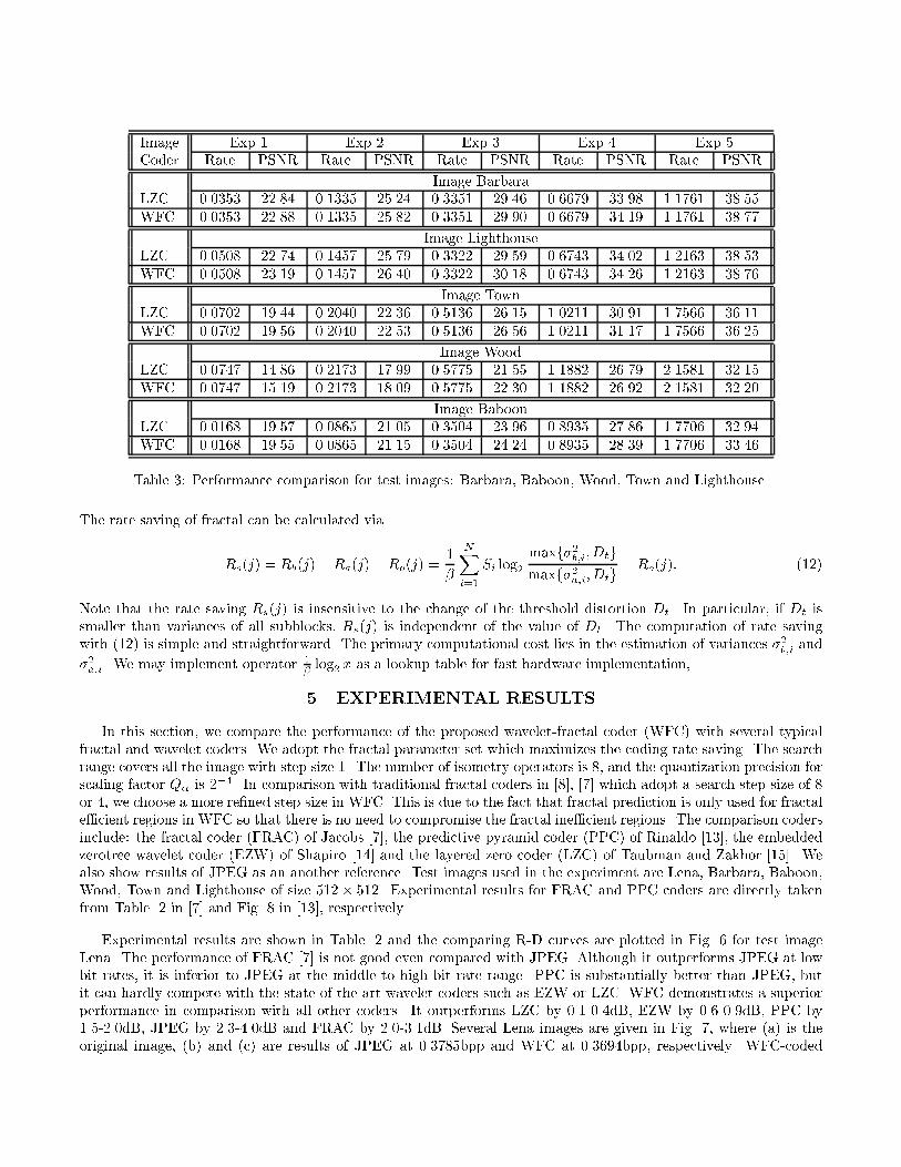
Image Exp 1 Exp 2 Exp 3 Exp 4 Exp 5Coder Rate PSNR Rate PSNR Rate PSNR Rate PSNR Rate PSNR
Image BarbaraLZC 0.0353 22.84 0.1335 25.24 0.3351 29.46 0.6679 33.98 1.1761 38.55WFC 0.0353 22.88 0.1335 25.82 0.3351 29.90 0.6679 34.19 1.1761 38.77
Image LighthouseLZC 0.0508 22.74 0.1457 25.79 0.3322 29.59 0.6743 34.02 1.2163 38.53WFC 0.0508 23.19 0.1457 26.40 0.3322 30.18 0.6743 34.26 1.2163 38.76
Image TownLZC 0.0702 19.44 0.2040 22.36 0.5136 26.15 1.0211 30.91 1.7566 36.11WFC 0.0702 19.56 0.2040 22.53 0.5136 26.56 1.0211 31.17 1.7566 36.25
Image WoodLZC 0.0747 14.86 0.2173 17.99 0.5775 21.55 1.1882 26.79 2.1581 32.15WFC 0.0747 15.19 0.2173 18.09 0.5775 22.30 1.1882 26.92 2.1581 32.20
Image BaboonLZC 0.0168 19.57 0.0865 21.05 0.3504 23.96 0.8935 27.86 1.7706 32.94WFC 0.0168 19.55 0.0865 21.15 0.3504 24.24 0.8935 28.39 1.7706 33.46
Table 3: Performance comparison for test images: Barbara, Baboon, Wood, Town and Lighthouse.
The rate saving of fractal can be calculated via
Rs(j) = Rb(j)� Ra(j)�Ro(j) =1
�
NXi=1
Si log2maxf�2b;i; Dtgmaxf�2a;i; Dtg �Ro(j): (12)
Note that the rate saving Rs(j) is insensitive to the change of the threshold distortion Dt. In particular, if Dt issmaller than variances of all subblocks, Rs(j) is independent of the value of Dt. The computation of rate savingwith (12) is simple and straightforward. The primary computational cost lies in the estimation of variances �2b;i and
�2a;i. We may implement operator 1� log2 x as a lookup table for fast hardware implementation,
5 EXPERIMENTAL RESULTS
In this section, we compare the performance of the proposed wavelet-fractal coder (WFC) with several typicalfractal and wavelet coders. We adopt the fractal parameter set which maximizes the coding rate saving. The searchrange covers all the image with step size 1. The number of isometry operators is 8, and the quantization precision forscaling factor Q� is 2�4. In comparison with traditional fractal coders in [8], [7] which adopt a search step size of 8or 4, we choose a more re�ned step size in WFC. This is due to the fact that fractal prediction is only used for fractale�cient regions in WFC so that there is no need to compromise the fractal ine�cient regions. The comparison codersinclude: the fractal coder (FRAC) of Jacobs [7], the predictive pyramid coder (PPC) of Rinaldo [13], the embeddedzerotree wavelet coder (EZW) of Shapiro [14] and the layered zero coder (LZC) of Taubman and Zakhor [15]. Wealso show results of JPEG as an another reference. Test images used in the experiment are Lena, Barbara, Baboon,Wood, Town and Lighthouse of size 512� 512. Experimental results for FRAC and PPC coders are directly takenfrom Table. 2 in [7] and Fig. 8 in [13], respectively.
Experimental results are shown in Table. 2 and the comparing R-D curves are plotted in Fig. 6 for test imageLena. The performance of FRAC [7] is not good even compared with JPEG. Although it outperforms JPEG at lowbit rates, it is inferior to JPEG at the middle to high bit rate range. PPC is substantially better than JPEG, butit can hardly compete with the state-of-the-art wavelet coders such as EZW or LZC. WFC demonstrates a superiorperformance in comparison with all other coders. It outperforms LZC by 0.1-0.4dB, EZW by 0.6-0.9dB, PPC by1.5-2.0dB, JPEG by 2.3-4.0dB and FRAC by 2.0-3.1dB. Several Lena images are given in Fig. 7, where (a) is theoriginal image, (b) and (c) are results of JPEG at 0.3785bpp and WFC at 0.3694bpp, respectively. WFC-coded

0.2 0.3 0.4 0.5 0.6 0.730
31
32
33
34
35
36
37
38
Rate(bpp)
PS
NR
(dB
)
Figure 6: Rate-distortion performances for Lena using the (a) Fractal wavelet coder (FWC, the solid line with `+'),(b) Layered zero coder (LZC, the dotted line with `o'), (c) Embedded zerotree wavelet coder (EZW, the dash dottedline with `*' ), (d) Predictive pyramid coder (PPC, the dashed line with `X'), (e) Conventional fractal coder (FRAC,the dotted line with `*'), (f) JPEG (the dash dotted line with `o').
Lena looks much better than the JPEG-coded one subjectively. The di�erence in subjective appearance of WFC-and LZC-coded Lena is more subtle. Generally speaking, WFC-coded Lena appears better in the texture areas.Subjective qualities of the two coders are about the same in the edge and smooth regions. This can be partiallyexplained by the fact that most fractal-e�cient range blocks are in texture regions or around sharp edges. Rangeblocks using fractal prediction are marked with � in Fig. 7(d). At that particular bit rate, about 8% of the entireimage is applied with fractal prediction.
In the next experiment, we perform a more thorough comparison of WFC and LZC, which is the wavelet residuecoder of WFC. Our objective is to investigate the performance gain of fractal prediction. The experiments areperformed on images Barbara, Baboon, Wood, Town and Lighthouse. The experimental results are shown in Table. 3.In general, the gain of WFC over LZC is in the range of 0.0-0.8dB. The actual gain depends on the characteristicsof image and the operating bit rate. The gain is more for images with a lot of textured patterns and encoded at ahigher bit rate. Note that fractal prediction is used adaptively in WFC. For the extreme case that all range blocksare not e�cient for fractal prediction, we only lose bits for the coding of a blank prediction status image. It is alsoworthwhile to point out that there is only one case among 30 comparisons (i.e. Baboon image coded at 0.0168bpp)that WFC is inferior to LZC by 0.02dB. For all other 29 cases, WFC performs better with the PSNR gain varyingfrom 0.0 to 0.8dB. The better R-D performance is however achieved by a higher computational cost.
There is one additional interesting observation from the above experiments. As the contractive mapping providesa tool for interscale wavelet prediction, it is not e�cient for all image regions. When integrated with the state-of-the-art wavelet coder (LZC), approximately 8% of the entire image region in Lena bene�ts from the use of fractalprediction. Fractal e�cient regions are usually the ones that consume more coding bits in typical wavelet coders.For example, LZC devotes around 17% of the total coding bits to the 8% fractal e�cient region in Lena. Clearly, theincorporation of an additional fractal prediction unit in the wavelet coder does provide a better R-D performance.
6 CONCLUSIONS AND EXTENSIONS
In this research, the fractal coder is integrated with the wavelet coder and constructs a wavelet-fractal coder(WFC) with a superior R-D performance. Fractal prediction used in WFC includes: the contractive operator thatprovides prediction across wavelet scales, the scaling operator that shrinks prediction coe�cients, and the isometry

operator which shu�es pixels within and across the subbands. As in DPCM or motion compensated video coding,the residue of fractal prediction is further encoded by the state-of-the-art wavelet coder. A rule of low complexity wasdeveloped to estimate the overhead information required and the bit rate saving achieved by using fractal predictionso that it is only applied to fractal e�cient regions. This rule optimizes the R-D performance and depends only onthe variance of the source and the codec control parameter, i.e. the threshold distortion. Wavelet coe�cients in otherregions are encoded directly with successive quantization and context-based adaptive arithmetic coding. The R-Dcriterion can also be used to determine the optimal fractal parameter set which maximizes the bit rate saving. WFCoutperforms JPEG, typical fractal and wavelet coders by 2.3-4.0dB, 1.5-3.1dB and 0.1-0.9dB, respectively. The resultclearly demonstrates that the incorporation of fractal prediction provides a substantial performance improvement forthe wavelet coder.
Currently, WFC uses a constant range-domain block size K. Further performance improvement is expected byvarying the block size in fractal prediction. Another shortcoming of WFC is that it is computationally intensive inthe encoding part. For practical applications, it is important to reduce the complexity of fractal search. This canbe achieved by either reducing the size of the domain pool, or adopting fast fractal search schemes [3] which greatlyreduce the search complexity with little additional degradation. It is worthwhile to perform a thorough study on thetradeo� of complexity reduction and the degradation of the R-D performance.
7 REFERENCES
[1] M. Antonini, M. Barlaud, P. Mathieu, and I. Daubechies, \Image coding using wavelet transform," IEEE Trans.
on Image Processing, Vol. 1, pp. 205{230, Apr. 1992.[2] G. Caso and C.-C. J. Kuo, \New results for fractal/ wavelet image compression," in SPIE Visual Communications
and Image Processing '96, vol. 2727, (Orlando, FL), pp. 536{547, Mar. 1996.[3] G. Caso, P. Obrador, and C.-C. J. Kuo, \Fast methods for fractal image encoding," in SPIE Visual Communi-
cations and Image Processing '95, vol. 2501, (Taiwan), pp. 583{594, 1995.[4] G. Davis, \Adaptive self-quantization of wavelet subtrees: a wavelet-based theory of fractal image compression,"
in Wavelet Applications in Signal and Image Processing III, SPIE Vol. 2569 (A. F. Laine, M. A. Unser, andM. V. Wickerhauser, eds.), (San Diego, CA), pp. 294{306, July 1995.
[5] D. L. Duttweiler and C. Chamzas, \Probability estimation in arithmetic and adaptive hu�man entropy coders,"IEEE Trans. on Image Processing, Vol. 4, pp. 237{246, Mar. 1995.
[6] Y. Fisher (ed.), Fractal Image Compression: Theory and Applications, Springer-Verlag, New York, 1995.[7] E. W. Jacobs, Y. Fisher, and R. D. Boss, \Image compression: a study of the iterated transform method,"
Signal Processing, Vol. 29, pp. 251{263, 1992.[8] A. E. Jacquin, \Image coding based on a fractal theory of iterated contractive image transformations," IEEE
Trans. on Image Processing, Vol. 1, No. 1, pp. 18{30, Jan. 1992.[9] J. Li, P.-Y. Cheng, and C.-C. J. Kuo, \On the Improvements of Embedded Zerotree Wavelet (EZW) Coding," in
SPIE: Visual Communication and Image Processing'95, vol. 2501, (Taipei, Taiwan), pp. 1490{1501, May 1995.[10] J. Li, P.-Y. Cheng, and C.-C. J. Kuo, \AWavelet Transform Approach to Video Compression," in SPIE: Wavelet
Applications II, vol. 2491, (Orlando, FL), pp. 1107{1118, Apr. 17-21 1995.[11] J. Li, P.-Y. Cheng, and C.-C. J. Kuo, \Embedded wavelet packet image coder With fast rate-distortion optimized
decomposition," in SPIE: Visual Communication and Image Processing'97, vol. 3204, (San Jose, CA), Feb. 1997.[12] A. P. Pentland, \Fractal-Based Description of Natural Scenes," IEEE Trans. on Pattern Analysis and Machine
Intelligence, Vol. 6, pp. 661{674, Nov. 1984.[13] R. Rinaldo and G. Calvagno, \Image coding by block prediction of multiresolution subimages," IEEE Trans.
on Image Processing, Vol. 4, pp. 909{920, July 1995.[14] J. Shapiro, \Embedded image coding using zerotrees of wavelet coe�cients," IEEE Trans. on Signal Processing,
Vol. 41, No. 12, pp. 3445{3462, Dec. 1993.[15] D. Taubman and A. Zakhor, \Multirate 3-D subband coding of video," IEEE Trans. on Image Processing, Vol. 3,
No. 5, pp. 572{588, Sep. 1994.

(a) (b)
(c) (d)
Figure 7: The Lena experimental results. We show (a) the original Lena, (b) the JPEG coded Lena at 0.3785bpp,33.34dB, (c) the wavelet fractal (WFC) coded Lena at 0.3694bpp, 35.84dB, (d) the fractal e�cient regions ( markedwith � ).