jig design - kelsey bradley's portfolio...
TRANSCRIPT

ITCD – 301-001

Workpiece drawing factors
• Size•Shape•Composition•Dimensions•Specifications

Tolerance
Total amount of dimensional variation
Designer specifies an unattainable condition
Designer specifies a degree of error
Two limits must be set
Individual limits for critical drawings
General limits for not so critical drawings
May be indirectly placed in BOM
Function, appearance and cost

Positional Tolerance

Conversion Charts

Conversion Charts

Gaging Principles
•Gage tolerance determined from the amount of workpiece tolerance•10% rule applied for a working gages•Working gage used by production workers during manufacture•5% rule applied for inspection gages•Inspection gages are used by the inspection department•10% rule applied to master gages•Master gages used for checking the accuracy of other gages

Classes of gagemakers’ tolerances
•Class XX gages are precision-smoothed to the closest tolerances possible and used as master gages for final close-tolerance inspection•Class X gages are precision-smoothed to close tolerances and used for some types of master gage work and close-tolerance inspection and working gages•Class Y gages are precision-smoothed to slightly larger tolerances than Class X gages and used for inspection and working gages•Class Z gages are precision-lapped and used as working gages where part tolerances are large and number of pieces to be gages is small

Standard gagemakers’ tolerances

Allocation of gage tolerances
•Decide the tolerance for a specific gage•Direction of that allowance should be decided•Bilateral system•Unilateral system•Choice depends on the product and facilities for production•Objective is the economical production of full usable parts•Rejection of bad pieces and acceptance of good parts

Systems of gage tolerance allocation

Bilateral System
•If the diameter of the hole to be gaged is 1.2500+/- 0.0006 in., then the work tolerance is 0.0012 in.•Hole size may vary from 1.2506 to 1.2494 in.•Use 10% of the total work tolerance as gage tolerance•Gage tolerance is then 0.00012 in.•From table 9.1, this diameter requires a class Z gage tolerance•Hence, the diameter of the no-go gage would be 1.2506 +/-0.00006 in.•Disadvantage – If the hole to be gaged is reamed to the low limit, say, 1.2494 in., and if the no-go gage is at the low limit, 1.24934 in, then the gage enters the hole and part passes inspection

Unilateral System
•Work tolerance zone includes the gage tolerance zone•If the diameter of the hole to be gaged is 1.2500+/- 0.0006 in., then the work tolerance is 0.00012 in.•Use 10% of the working tolerance as the gage tolerance•Go-gage diameter would be 1.24940 + 0.00012 in.•No-go-gage diameter would be 1.25060 -0.00012 in.

Gage wear allowance
•Multiple measurements create gage wear•Wear allowance is added to the nominal diameter of a go-plug and subtracted from that of a go-ring gage•Material from which gage and work are to be made is important•Quantity of work•Type of gaging operation to be performed•Important to establish a specific amount of wear allowance•Avoids any controversy to the accuracy of the gage

Hardened and ground plug gauge

Replaceable thread and plug gauges

Gage measurement
•Measurement compares an amount or length with a known standard•All dimensional measurement is end measurement•End measurement is determined by origin, both the standard and the property being measured should start at the same point•Every workpiece related to the primary, secondary and tertiary datums must be measured by three planes at right angles to each other•Every dimension has its origin in one of the three planes

Surface plate

Templates

Commercial Gages

Screw pitch gage
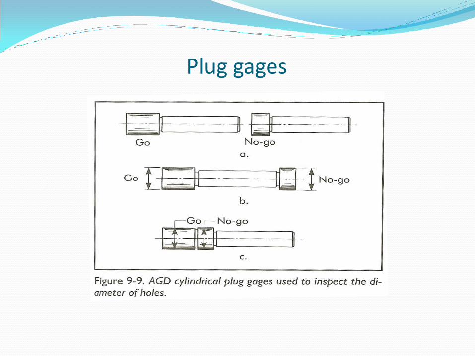
Plug gages

Cylindrical plug gages

Special plug gages

Ring gage

Special ring gages

Snap gage

Snap gages

Snap gages

Special snap gage

Gage comparison

Flush-pin gage

Dial indicators

Application of dial indicator
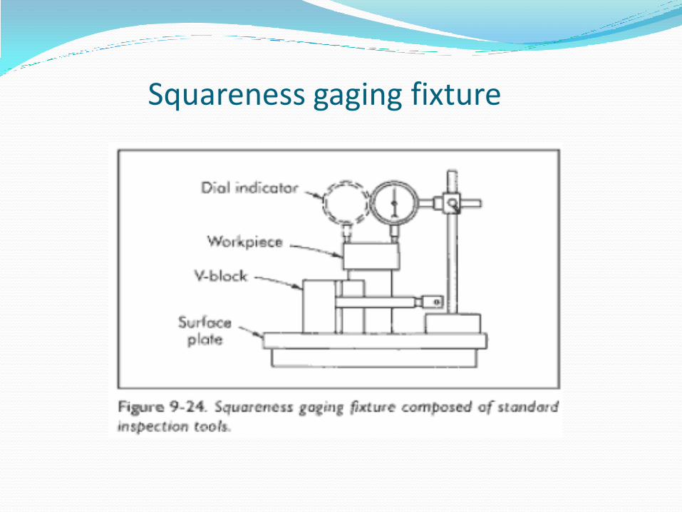
Squareness gaging fixture

Gaging fixture - Accessories

Electric or electronic gages

Application data for electronic gaging

Optical projection gaging

Chart gages for optical gage

CMM

Gaging methods - Flatness

Gaging methods – Straightness

Gaging methods – Straightness

Gaging methods – Line Profile

Gaging methods – Squareness

Gaging methods – Perpendicularity

Functional gage

Parallelism

Runout

References
Fundamentals of tool design, fifth edition, Society of Manufacturing Engineers
Donaldson, and Lecain, Tool Design, McGraw Hill

Questions?