jharkhand rai university
TRANSCRIPT

1
JHARKHAND RAI UNIVERSITY RANCHI
CIVIL ENGINEERING LAB MANUAL
THEORY OF STRUCTURE
2
Contents
List of Experiment
EXPERIMENT NO. 1 To verify clerk Maxwell’s reciprocal theorem ................................... 3
Experiment – 2 Elastic properties of beams .............................................................. 5
EXPERIMENT NO- 3 Two hinged Arch ............................................................................... 7
Experimental – 4 Three hinged Arch ............................................................................ 9
Experiment- 5 Behavior of struts ............................................................................ 11
3
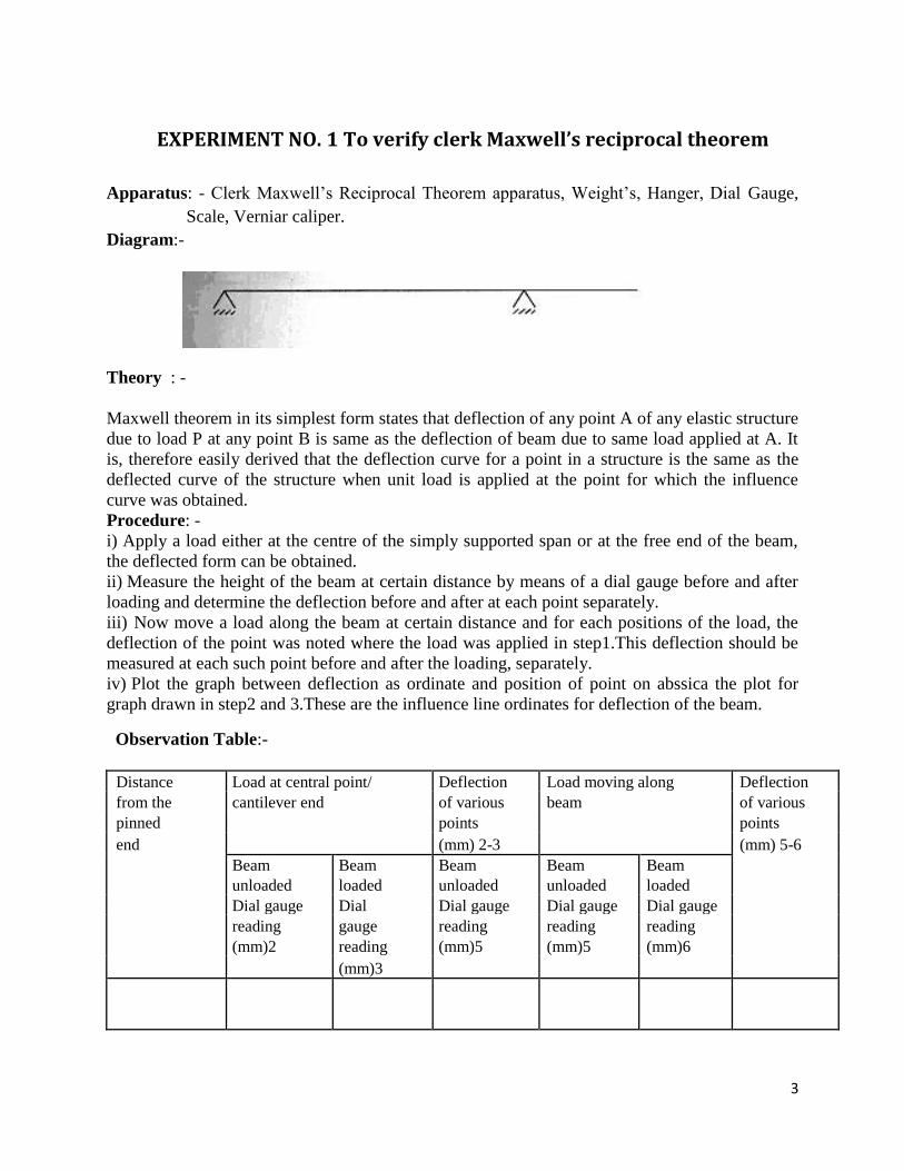
EXPERIMENT NO. 1 To verify clerk Maxwell’s reciprocal theorem
Apparatus: - Clerk Maxwell’s Reciprocal Theorem apparatus, Weight’s, Hanger, Dial Gauge,
Scale, Verniar caliper.
Diagram:-
Theory : -
Maxwell theorem in its simplest form states that deflection of any point A of any elastic structure
due to load P at any point B is same as the deflection of beam due to same load applied at A. It
is, therefore easily derived that the deflection curve for a point in a structure is the same as the
deflected curve of the structure when unit load is applied at the point for which the influence
curve was obtained.
Procedure: -
i) Apply a load either at the centre of the simply supported span or at the free end of the beam,
the deflected form can be obtained.
ii) Measure the height of the beam at certain distance by means of a dial gauge before and after
loading and determine the deflection before and after at each point separately.
iii) Now move a load along the beam at certain distance and for each positions of the load, the
deflection of the point was noted where the load was applied in step1.This deflection should be
measured at each such point before and after the loading, separately.
iv) Plot the graph between deflection as ordinate and position of point on abssica the plot for
graph drawn in step2 and 3.These are the influence line ordinates for deflection of the beam. Observation Table:-
Distance Load at central point/ Deflection Load moving along Deflection
from the cantilever end of various beam of various
pinned points points
end (mm) 2-3 (mm) 5-6
Beam Beam Beam Beam Beam
unloaded loaded unloaded unloaded loaded
Dial gauge Dial Dial gauge Dial gauge Dial gauge
reading gauge reading reading reading
(mm)2 reading (mm)5 (mm)5 (mm)6
(mm)3

4
Result: - The Maxwell reciprocal theorem is verified experimentally and analytically. Precaution: - i) Apply the loads without any jerk.
ii) Perform the experiment at a location, which is away from any
iii) Avoid external disturbance.
Ensure that the supports are rigid.
5
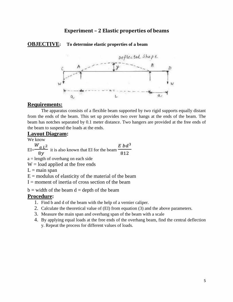
Experiment – 2 Elastic properties of beams
OBJECTIVE: To determine elastic properties of a beam
Requirements: The apparatus consists of a flexible beam supported by two rigid supports equally distant
from the ends of the beam. This set up provides two over hangs at the ends of the beam. The
beam has notches separated by 0.1 meter distance. Two hangers are provided at the free ends of
the beam to suspend the loads at the ends.
Layout Diagram: We know
EI=𝑊
𝑎 𝐿2
8𝑦 it is also known that EI for the beam
𝐸 𝑏𝑑3
812
a = length of overhang on each side
W = load applied at the free ends
L = main span
E = modulus of elasticity of the material of the beam
I = moment of inertia of cross section of the beam
b = width of the beam d = depth of the beam
Procedure: 1. Find b and d of the beam with the help of a vernier caliper. 2. Calculate the theoretical value of (EI) from equation (3) and the above parameters. 3. Measure the main span and overhang span of the beam with a scale 4. By applying equal loads at the free ends of the overhang beam, find the central deflection
y. Repeat the process for different values of loads.

6
Observation:
Result Compare the experimental vale of (EI) with the theoretically obtained value.
Precautions: i. Apply the loads without any jerk. ii. Perform the experiment at a location, which is away from any external disturbance. iii. Ensure that the supports are rigid. iv. The load applied should be within the allowed limits for the apparatus
7
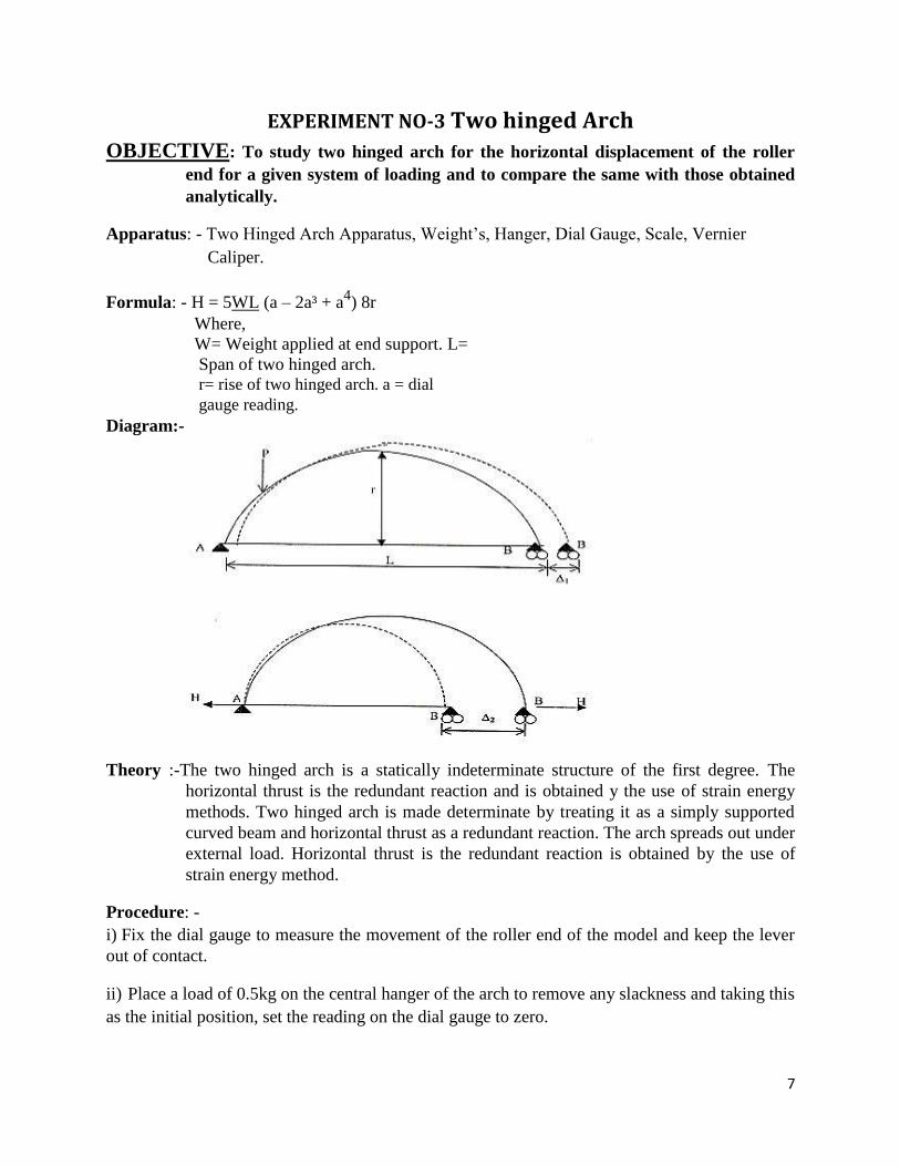
EXPERIMENT NO-3 Two hinged Arch
OBJECTIVE: To study two hinged arch for the horizontal displacement of the roller
end for a given system of loading and to compare the same with those obtained
analytically. Apparatus: - Two Hinged Arch Apparatus, Weight’s, Hanger, Dial Gauge, Scale, Vernier
Caliper.
Formula: - H = 5WL (a – 2a³ + a4) 8r
Where,
W= Weight applied at end support. L=
Span of two hinged arch. r= rise of two hinged arch. a = dial
gauge reading. Diagram:- Theory :-The two hinged arch is a statically indeterminate structure of the first degree. The
horizontal thrust is the redundant reaction and is obtained y the use of strain energy
methods. Two hinged arch is made determinate by treating it as a simply supported
curved beam and horizontal thrust as a redundant reaction. The arch spreads out under
external load. Horizontal thrust is the redundant reaction is obtained by the use of
strain energy method. Procedure: - i) Fix the dial gauge to measure the movement of the roller end of the model and keep the lever
out of contact. ii) Place a load of 0.5kg on the central hanger of the arch to remove any slackness and taking this
as the initial position, set the reading on the dial gauge to zero.
8
iii) iii) Now add 1 kg weights to the hanger and tabulated the horizontal movement of the roller
end with increase in the load in steps of 1 kg. Take the reading up to 5 kg load. Dial gauge
reading should be noted at the time of unloading also.
iv) Plot a graph between the load and displacement (Theoretical and Experimental)
compare. Theoretical values should be computed by using horizontal displacement formula. v) Now move the lever in contact with 200gm hanger on ratio 4/1 position with a 1kg load
on the first hanger. Set the initial reading of the dial gauge to zero.
vi) Place additional 5 kg load on the first hanger without shock and observe the dial gauge
reading.
vii) Restore the dial gauge reading to zero by adding loads to the lever hanger, say the load
is w kg.
viii) The experimental values of the influence line ordinate at the first hanger position shall
be 4w
ix) Repeat the steps 5 to 8 for all other hanger loading positions and tabulate. Plot the
influence line ordinates.
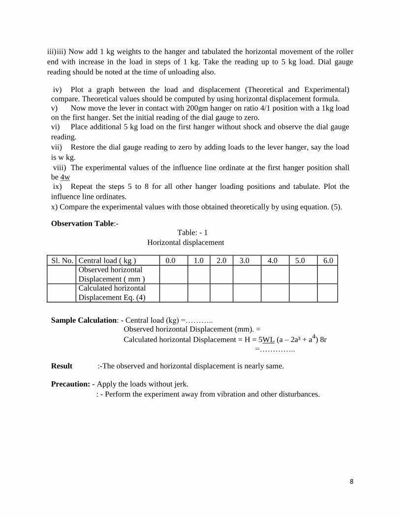
x) Compare the experimental values with those obtained theoretically by using equation. (5). Observation Table:-
Table: - 1 Horizontal displacement
Sl. No. Central load ( kg ) 0.0 1.0 2.0 3.0 4.0 5.0 6.0
Observed horizontal
Displacement ( mm )
Calculated horizontal
Displacement Eq. (4) Sample Calculation: - Central load (kg) =………..
Observed horizontal Displacement (mm). =
Calculated horizontal Displacement = H = 5WL (a – 2a³ + a4) 8r
=………….. Result :-The observed and horizontal displacement is nearly same.
Precaution: - Apply the loads without jerk.
: - Perform the experiment away from vibration and other disturbances.
9
Experimental – 4 Three hinged Arch
OBJECTIVE: Experimental and analytical study of 3 hinged arch and influence line for
horizontal thrust.
Requirements: A three hinged arch is statically determined with the axial thrust assisting in maintaining
the stability. The model has a span of 100cm and rise of 25cm with hinges at supports and crown. One of
the ends rests on rollers along the horizontal span of the applications of load. This marked at the
equidistant for the application of load. This being a statically determined structure, the horizontal thrust
developed under the action of any load system can be theoretically calculated and will also be measured
directly by neutralization of the outward movement of the roller end.
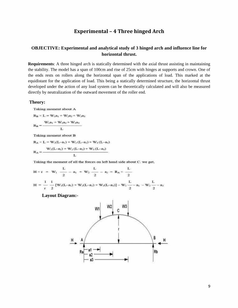
Theory:
Layout Diagram:-
10
Procedure:
1. Balance the self weight of the arch by putting load on the thrust hanger till the appropriate equilibrium
conditions are obtained. The moveable end of the arch is positioned such that it shows a tendency to move
inside on tapping the supporting table.
2. Place a few loads on the arch in any chosen positions. Balance these by placing additional weights on
the hanger for horizontal thrust. The additional weights on the thrust hanger give the experimental value
of the horizontal thrust.
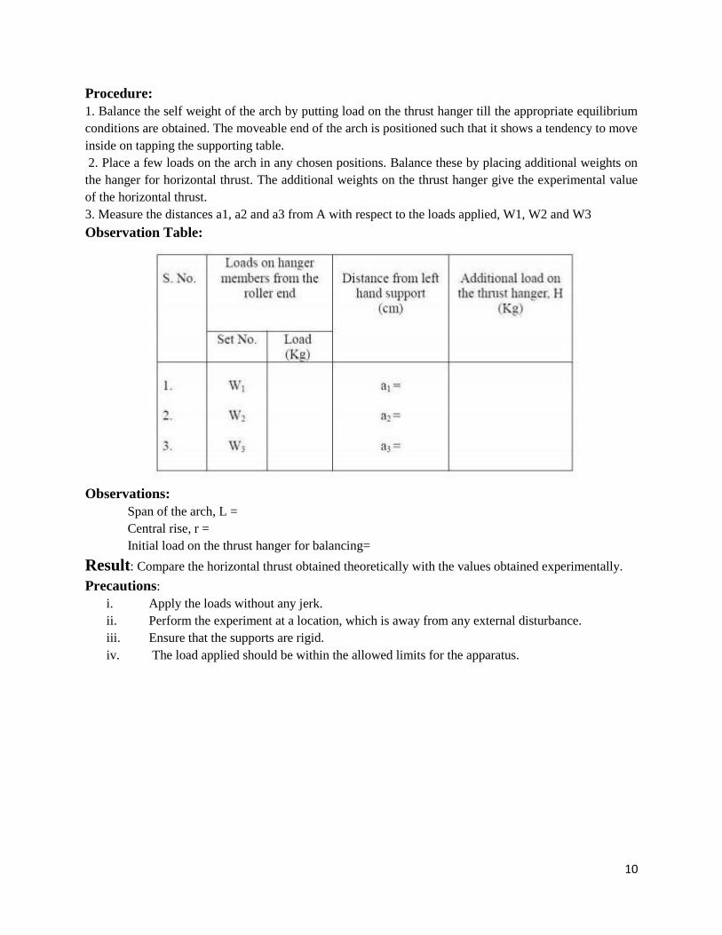
3. Measure the distances a1, a2 and a3 from A with respect to the loads applied, W1, W2 and W3
Observation Table:
Observations:
Span of the arch, L =
Central rise, r =
Initial load on the thrust hanger for balancing=
Result: Compare the horizontal thrust obtained theoretically with the values obtained experimentally.
Precautions:
i. Apply the loads without any jerk.
ii. Perform the experiment at a location, which is away from any external disturbance.
iii. Ensure that the supports are rigid.
iv. The load applied should be within the allowed limits for the apparatus.
11
Experiment-5 Behavior of struts
OBJECTIVE: Experimental and analytical study of behavior of struts with various end
conditions.
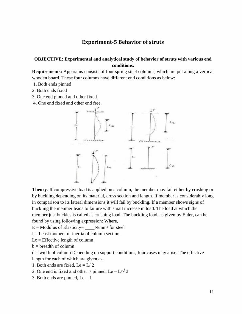
Requirements: Apparatus consists of four spring steel columns, which are put along a vertical
wooden board. These four columns have different end conditions as below:
1. Both ends pinned
2. Both ends fixed
3. One end pinned and other fixed
4. One end fixed and other end free.
Theory: If compressive load is applied on a column, the member may fail either by crushing or
by buckling depending on its material, cross section and length. If member is considerably long
in comparison to its lateral dimensions it will fail by buckling. If a member shows signs of
buckling the member leads to failure with small increase in load. The load at which the
member just buckles is called as crushing load. The buckling load, as given by Euler, can be
found by using following expression: Where,
E = Modulus of Elasticity= ____N/mm² for steel
I = Least moment of inertia of column section
Le = Effective length of column
b = breadth of column
d = width of column Depending on support conditions, four cases may arise. The effective
length for each of which are given as:
1. Both ends are fixed, Le = L/ 2
2. One end is fixed and other is pinned, Le = L/√ 2
3. Both ends are pinned, Le = L

12
4. One end is fixed and other is free, Le = 2L
Where, L = Length of the column
Procedure:
1. Pin a graph paper on the wooden board behind the column.
2. Apply the load at the top of columns.
3. Note the buckling patterns for each of the four columns.
4. Trace the deflected shapes of the columns over the graph paper. Mark the points of change
of curvature of the curves and measure the effective or equivalent length for each case
separately. 5. Calculate the theoretical effective lengths and thus buckling loads by the
expressions given above and compare them with the observed values
Result:
1. Calculate the buckling load for each case
2. Study the shape of the curve and the points of buckling traced at the graph paper