jfkfj`lk - seaconseaconworldwide.com/wp-content/uploads/mini-con.pdf · - min 2 - rev xiii...
TRANSCRIPT

jfkfJ`lkUNDERWATER ELECTRICAL DRY-MATE CONNECTORS

- MIN 2 -www.seaconworldwide.com
REV XIII
jfkfJ`̀lk SERIES CONTENTS PAGE
jfkfJ`̀lk pbofbp
Introduction ..................................................................................................................................................................................................
Availability ....................................................................................................................................................................................................
Applications .................................................................................................................................................................................................
Testing .........................................................................................................................................................................................................
Part Number System ...................................................................................................................................................................................
General Information .....................................................................................................................................................................................
Standard jfkfJ`lk Configurations ..............................................................................................................................................................
Reversed jfkfJ`lk Connectors (V-MIN) ....................................................................................................................................................
Fiber Optic jfkfJ`lk Connectors ...............................................................................................................................................................
Self Wiping jfkfJ`lk Connectors ..............................................................................................................................................................
jfkfJ`lk PBOF ..........................................................................................................................................................................................
High Pressure Connectors ..........................................................................................................................................................................
Field Installation ...........................................................................................................................................................................................
Recommended Tightening Torque................................................................................................................................................................
Pressure Ratings .........................................................................................................................................................................................
Exploded View (MIN-BCR / CCR) ...............................................................................................................................................................
Dimension Details:
MIN-BCR .................................................................................................................................................................................................
MIN-FCR .................................................................................................................................................................................................
MIN-BCR-DO (DUAL O-RING) ...............................................................................................................................................................
MIN-CCR ...............................................................................................................................................................................................
MIN-CCP ...............................................................................................................................................................................................
Product News - MINI-CON Dummy Connectors ...................................................................................................................................
MIN-DSR/MIN-DSRL (LONG) ...............................................................................................................................................................
MIN-DSP/MIN-DSPL (LONG) ...............................................................................................................................................................
MIN-PSR/MIN-PSRL (LONG) ...............................................................................................................................................................
MIN-PSP/MIN-PSPL (LONG).................................................................................................................................................................
MIN-CCP-PBOF-HP...............................................................................................................................................................................
MIN-CCP-PBOF-HP-RA ........................................................................................................................................................................
MIN-CCR-PBOF-HP...............................................................................................................................................................................
jfkfJ`lk Master Parts and Materials List ................................................................................................................................................
Maximum Cable O.D .................................................................................................................................................................................
Contact Configurations .........................................................................................................................................................................
Reversed (VMIN) Contact Configurations .................................................................................................................................................
Fiber Optic Contact Configurations ...........................................................................................................................................................
jáÅêç jfkfJ`̀lk pbofbp SECTION .........................................................................................................................................
SECTION PAGE
MIN 3
MIN 3
MIN 3
MIN 3
MIN 3
MIN 4
MIN 4
MIN 4
MIN 4
MIN 4
MIN 4
MIN 5
MIN 5
MIN 5
MIN 5
MIN 6
MIN 7
MIN 8
MIN 9
MIN 10
MIN 10
MIN 11
MIN 12
MIN 12
MIN 12
MIN 12
MIN 13
MIN 13
MIN 14
MIN 15
MIN 15
MIN 16-18
MIN 19
MIN 20
MIN 21-26
- MIN 3 -www.seaconworldwide.com
REV XIII
jfkfJ`̀lk SERIES
INTRODUCTIONpb^`lk's well established jfkfJ`lk range was originally devel-oped for the purpose of supplying small diameter, high density andhigh pressure connectors. Dry mateable, this connector series ismanufactured from 316 Stainless Steel as standard, although othermaterials are available upon request including Titanium andMonel™. The inserts are manufactured from Glass ReinforcedEpoxy (GRE) with copper alloy, gold plated contacts although glasssealed inserts are also available for high pressure applications. ThejfkfJ`lk series also offers optical and hybrid versions along withPBOF, PBOF-HP (High Pressure), reversed miniature inserts andself wiping miniatures. For more information please refer to pages4-5 of this brochure.
AVAILABILITYWith the introduction of the MIN-D and MIN-E connectors, the jfkfJ`lk connector series is now available in 13 shell sizes with 1 to 203contacts including coax and has a pressure rating of upto 20,000 psi(approximately 45,000 ft/13,700m).
APPLICATIONSThe jfkfJ`lk range has been supplied to numerous Naval pro-grams and has become the connector choice for a number of naviesaround the world. Other applications include drilling systems, umbil-ical links and ROV's.
TESTINGBefore the jfkfJ`lk series was first introduced, it underwent typeapproval testing and since then the range has been subjected toadditional testing for specific projects or programs, some of whichare listed below:
Environmental Salt Spray (Corrosion)
• Tested in accordance with MIL-STD-202, Method 101.Humidity (Steady State)
• Tested in accordance with MIL-STD-202, Method 103.Thermal Shock
• Tested in accordance with MIL-STD-202, Method 107.Hydrostatic Pressure
• Tested in accordance with MIL-STD-1344, Method 1006.
PhysicalUnderwater Explosion Shock
• Tested in accordance with MIL-S-901, High Impact,Heavy Weight.
Vibration (Mechanical) • Tested in accordance with MIL-STD-167, Type 1.
ElectricalDielectric Withstanding Voltage
• Tested in accordance with MIL-STD-202, Method 301.Insulation Resistance
• Tested in accordance with MIL-STD-202, Method 302.
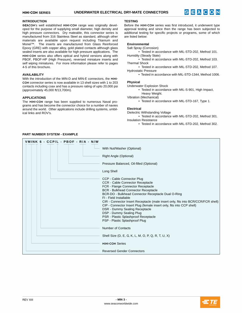
PART NUMBER SYSTEM - EXAMPLE
With Nut/Washer (Optional)
Right Angle (Optional)
Pressure Balanced, Oil-filled (Optional)
Long Shell
CCP - Cable Connector PlugCCR - Cable Connector ReceptacleFCR - Flange Connector ReceptacleBCR - Bulkhead Connector ReceptacleBCR-DO - Bulkhead Connector Receptacle Dual O-RingFI - Field InstallableCIR - Connector Insert Receptacle (male insert only, fits into BCR/CCR/FCR shell)CIP - Connector Insert Plug (female insert only, fits into CCP shell)DSR - Dummy Sealing ReceptacleDSP - Dummy Sealing PlugPSR - Plastic Splashproof ReceptaclePSP - Plastic Splashproof Plug
Number of Contacts
Shell Size (D, E, G, K, L, M, O, P, Q, R, T, U, X)
jfkfJ`lk Series
Reversed Gender Connectors
V M I N K 6 - C C P / L - P B O F - R / A - N / W
UNDERWATER ELECTRICAL DRY-MATE CONNECTORS

- MIN 4 -www.seaconworldwide.com
REV XIII
jfkfJ`̀lk SERIES UNDERWATER ELECTRICAL DRY-MATE CONNECTORS
GENERAL INFORMATIONCATEGORY VALUECOMPONENT MATERIAL
MATED PRESSURE Varies by product up to 20,000 psi Mated and potted depending on shell material
VOLTAGE 600 VDC as standard although higher voltage ratings are available. Please contact pb^`lk for further information
CURRENT RATING Up to 23 amps dependent on contact size and cable
BULKHEAD BODY (BCR/FCR) 316 Stainless Steel
CCP BODY 316 Stainless Steel c/w CA630 engaging nut
CONTACT INSERT Glass filled epoxy per B/A XS-2748
ELECTRICAL CONTACTS Copper alloy gold plated per MIL-G-45204
ENGAGING NUT CA630
O-RING Nitrile (formerly known as Buna N)
OPTIONS:· Pressure Balanced Oil Filled (PBOF).· Higher voltages.· Field installable boots.· Coax and fiber optic hybrids.· Custom keying.· Connector/cable terminations.· Pigtails on bulkhead connectors.· Pressure Balanced Oil Filled (PBOF) termination and assembly.· Open face pressure ratings and testing.· Available in alternative materials: Aluminum, Titanium, Monel™, PEEK (Polyetheretherketone) etc.
NOTES:· Connectors are designed for installation on one atmosphere vessels. Please contact pb^`lk for recommendations if using compensated vessels.
STANDARD jfkfJ`̀lk CONFIGURATIONSThe below table shows our standard configurations that are more cost effective and more readily available. For further details please contactpb^`lk.
CONNECTOR G K M O
BCR 10#22; 7#20 19#22; 10#20; 4#16 37#22; 26#20; 3#14; 4#10; 10#16 On Request
CCP 10#22; 7#20 19#22; 10#20; 4#16 37#22; 26#20; 3#14; 4#10; 10#16 56#22; 44#20
CCPL On Request 19#22; 10#20; 4#16 37#22; 26#20; 3#14; 4#10; 10#16 On Request
FCR 10#22; 7#20 19#22; 10#20; 4#16 37#22; 26#20; 3#14; 4#10; 10#16 56#22; 44#20
FCRL On Request 19#22; 10#20; 4#16 37#22; 26#20; 3#14; 4#10; 10#16 On Request
REVERSED jfkfJ`̀lk CONNECTORS (V-MIN)The "V" before the MIN prefix in the Part Numbering System (seepage 3) represents a reversed miniature insert. Many of our bulk-head connectors are available with sockets instead of pins and thecorresponding cable plugs have pins instead of sockets.
Reversed jfkfJ`lk's are an option for applications that requiredesign of cabling/harnessing systems to be electrically sound withrespect to "power on" safety requirements.
NOTE:Reversal of sockets and pins may not be required as the pins in thestandard bulkhead connectors are recessed approximately onequarter of an inch (1/4"). Please refer to the contact configurationspage for further information or contact pb^`lk for recommenda-tions on your specific application.
FIBER OPTIC jfkfJ`̀lk CONNECTORSAs organizations in the subsea industry continue to develop moreapplications with fiber optic technology in mind, there has been adramatic increase in the quality and complexity of electro-optic con-nector configurations required to suit these applications. Multi-chan-nel hybrid connectors are finding increased usage in sonar and sur-veillance systems, real time video applications, ROV's/AUV's andgeophysical search equipment to name but a few of the industriestaking advantage of the latest fiber optic connection technology.
In order to serve the changing needs of it's customers, pb^`lk hasdeveloped a complete range of fiber optic products built to withstanda variety of environmental conditions, including hydrostatic pressure,thermal and explosive shock and vibration. As well as developingfiber optics for specific customer requirements, pb^`lk has addedfiber optic capabilities to existing electrical connector designs includ-ing the jfkfJ`lk range. For further information please see the jfkfJ`lk fiber optic contact configurations on page 20 and our OpticalHybrid Dry-Mate products section.
SELF WIPING jfkfJ`̀lk CONNECTORSWe have developed self wiping connectors to meet two require-ments. First, the rubber wipers at each socket location help cleanthe respective insulator around each male pin. This can help toremove contaminates or moisture that would otherwise lead to a lowinsulation resistance fault. Second, these connectors have a longerarcing path because of the wiper section and therefore can be ratedfor much higher voltages than would otherwise be possible in a con-nector of the same diameter. Please contact pb^`lk for additionalinformation and availability.
jfkfJ`̀lk PBOFThe time proven jfkfJ`lk PBOF connector system has beenupgraded. The new line which is called the jfkfJ`lk-PBOF-HP(High Pressure) has actually been in service with some of our cus-tomers for the last fifteen years. At this time, it is replacing the tradi-tional jfkfJ`lk PBOF across the board. The HP version will inter-mate with all previous jfkfJ`lk PBOF connectors but some compo-nents are different from before. For this reason, if you need replace-ment connector components, please contact pb^`lk for thoseneeds. For new applications, the HP connectors will be delivered.
As with previous jfkfJ`lk PBOF connectors, the HP design utilizesa high contact density layout. The HP style transfers the load with-out a valve by bearing on the insert. This is similar to a valve typesystem in that the force from the high pressure fluid in the hose istransferred to the bulkhead connector. We realize that our customershave many different applications for this type of system. Please con-tact us with your requirements and we can quote the appropriatebulkhead connector for your application.

- MIN 5 -www.seaconworldwide.com
REV XIII
jfkfJ`̀lk SERIES UNDERWATER ELECTRICAL DRY-MATE CONNECTORS
RECOMMENDED TIGHTENING TORQUE1. Only qualified technicians should perform engagement andtorquing operations.
2. Torque values are maximum value. Valves given are for drythreads (non-lubricated). The BCR torque rating assumes a dry,metal customer housing. If a non-metallic housing is used, torquerequirements will be lower. Consult pb^`lk for additional informa-tion.
3. Utilize inspection hole in engaging nuts to ensure completeengagement.
4. During engagement it may be necessary to use up to 50% of theengaging nut torque value.
5. After complete engagement a torque of upto the maximum listedvalue may be applied to ensure engaging nut will not disengage dur-ing use.
PRESSURE RATINGSAll jfkfJ`lk connectors and dummies, when mated, are pressure rated as follows:
These pressure ratings are for our standard 316 Stainless Steel connectors. Higher ratings may be achieved with alternate materials. Pleasecontact pb^`lk for further information.
The above information is based on pb^`lk terminations which are available on request.
NOTE:Connectors are designed for installation on one atmosphere vessels. Please contact pb^`lk for recommendations if using compensatedvessels.
SIZE NON-PBOF PBOF
MIND 16,000 NOT AVAILABLEMINE 16,000 NOT AVAILABLEMING 16,000 3,000MINK 12,000 3,000MINL 12,000 3,000MINM 12,000 3,000MINO 10,000 3,000MINP 10,000 2,000MINQ 6,500 2,000MINR 6,500 2,000MINT 6,500 NOT AVAILABLEMINU 6,500 NOT AVAILABLEMINX 6,500 NOT AVAILABLE
HIGH PRESSURE CONNECTORSThe jfkfJ`lk series can be manufactured with Titanium or highstrength material shells which will increase the mated pressure rat-ing to 20,000 psi mated. For high open face pressure ratings, mostjfkfJ`lk bulkhead connectors can be manufactured with a GlassSealed Contact Insert Receptacle (CIR). These inserts consist ofgold plated pins, compression glass sealed in a type 316 StainlessSteel contact web. Our standard glass sealed jfkfJ`lk’s are ratedat 10,000 psi, open face, or greater depending on the particular con-nector. These inserts are a direct replacement for our standardepoxy inserts and may be ordered separately. They may be used inthe Titanium shells mentioned above, or in standard shells. Pleasecontact pb^`lk for further information on ratings.
FIELD INSTALLATIONMost of the jfkfJ`lk CCP & CCR connectors are available for fieldinstallation. This capability is accomplished by installing our fieldinstallation boot as shown on the drawing of page 10. The boot ismolded of neoprene compound and is designed for sealing onto thecable and the connector shell. In order for the boot to accomplish it'ssealing task, the cable must be completely round, solid and free ofany nicks, indentations or voids. Optional hose clamps prevent acci-dentally dislodging the boot. When ordering the field installable bootplease specify the exact cable diameter as the hole in the boot ismade specifically according to the cable diameter to allow a propercompression fit.
GED
0
5
10
15
20
K L M O P Q R T U X
PSI X
100
0M
ATED
NO
N-P
BO
F
SHELL SIZES (D-X)
316SS Ti 6Al4V
- MIN 6 -www.seaconworldwide.com
REV XIII
jfkfJ`̀lk SERIES UNDERWATER ELECTRICAL DRY-MATE CONNECTORS
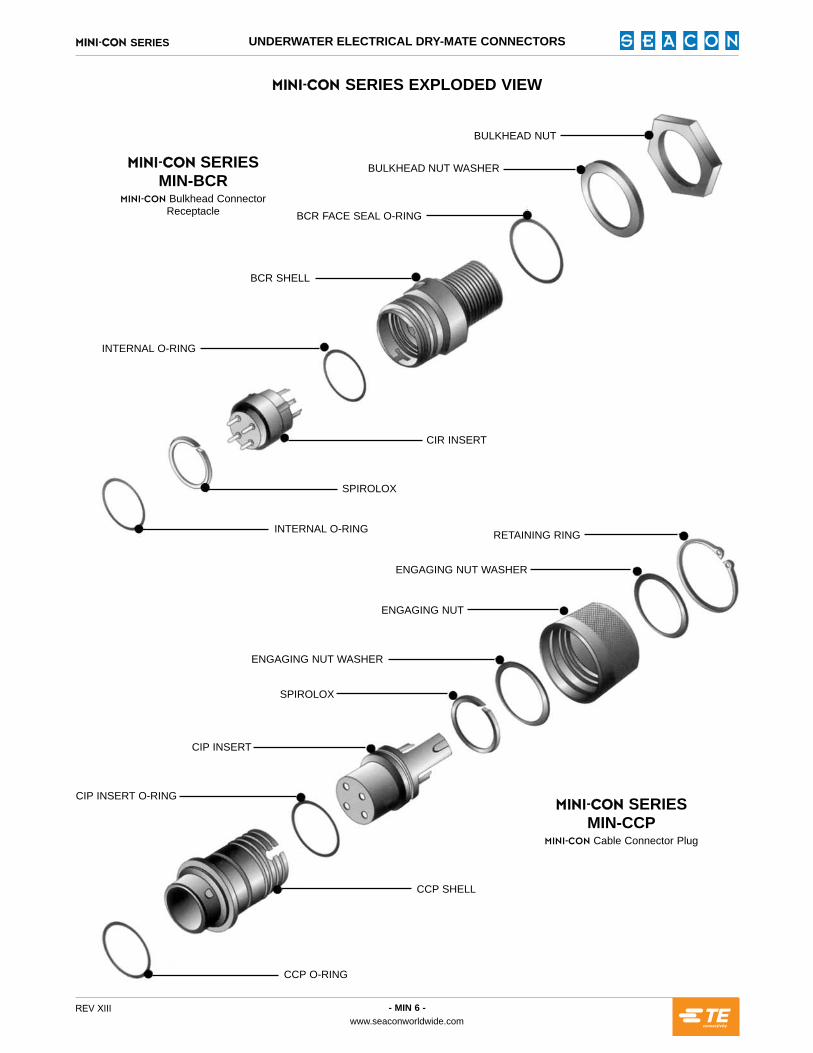
jfkfJ`̀lk SERIES EXPLODED VIEW
jfkfJ`̀lk SERIES MIN-BCR
jfkfJ`lk Bulkhead ConnectorReceptacle
jfkfJ`̀lk SERIES MIN-CCP
jfkfJ`lk Cable Connector Plug
CIR INSERT
INTERNAL O-RING
CCP O-RING
CCP SHELL
CIP INSERT O-RING
CIP INSERT
SPIROLOX
ENGAGING NUT WASHER
ENGAGING NUT
ENGAGING NUT WASHER
RETAINING RING
SPIROLOX
INTERNAL O-RING
BCR SHELL
BCR FACE SEAL O-RING
BULKHEAD NUT WASHER
BULKHEAD NUT

- MIN 7 -www.seaconworldwide.com
REV XIII
jfkfJ`̀lk SERIES DIMENSION DETAILS
jfkfJ`̀lk SERIES MIN-BCR
jfkfJ`lk Bulkhead Connector Receptacle Mates with MIN-CCP
Dummy Connector: MIN-DSP
MIND-BCR 3/8-24 UNF-2A 0.75 2-013 VH-31 2-011 0.62 0.62 0.72 0.62MINE-BCR 1/2-20 UNF-2A 0.87 2-015 VH-43 2-013 0.75 0.75 0.86 0.75MING-BCR 5/8-24 UNEF-2A 1.00 2-018 UR50 2-014 0.87 0.88 1.00 0.88MINK-BCR 3/4-20 UNEF-2A 1.12 2-019 UR62 2-016 1.00 1.00 1.16 1.00MINL-BCR 7/8-20 UNEF-2A 1.25 2-021 UR75 2-018 1.12 1.13 1.31 1.13MINM-BCR 1-20 UNEF-2A 1.37 2-023 UR81 2-019 1.25 1.25 1.44 1.25MINO-BCR 1 1/8-16 UN-2A 1.62 2-026 UR106 2-023 1.50 1.50 1.75 1.50MINP-BCR 1 1/4-16 UN-2A 1.75 2-028 UR118 2-025 1.62 1.63 1.88 1.63MINQ-BCR 1 3/8-16 UN-2A 1.87 2-029 UR137 2-028 1.75 1.75 2.00 1.75MINR-BCR 1 1/2-16 UN-2A 2.00 2-029 UR150 2-029 1.87 1.88 2.16 1.88MINT-BCR 2-16 UN-2A 2.50 2-034 UR175 2-031 2.37 2.38 2.75 2.38MINU-BCR 2 1/4-16 UN-2A 2.75 2-036 UR200 2-033 2.62 2.63 3.03 2.63MINX-BCR 2 3/4-16 UN-2A 3.50 2-041 UR250 2-037 3.15 3.16 3.63 3.16
CONNECTOR A - MOUNTINGTHREAD
B - Ø (INCHES) 2 - O-RING 7 - SPIROLOX 3 - O-RING C - WRENCH
FLATS (INCHES)8 - HEX NUT ACROSS
FLATS (INCHES)8 - HEX NUT ACROSS
POINTS (INCHES)9 - WASHER OD
(INCHES)
D 0.375 30-35E 0.500 50-55G 0.625 65-85K 0.750 75-100L 0.875 90-110M 1.000 120-150O 1.125 130-160P 1.250 140-170Q 1.375 150-180R 1.500 170-220T 2.000 210-250U 2.250 220-260X 2.750 240-280
SIZEBORE Ø +0.015
-0.000(INCHES)
BCR/LMOUNTING TORQUE*
(INCH-POUNDS)
BCR MOUNTING INFORMATION
NOTES:· * Torque specified is for dry metal threads.· For contact configurations please refer to pages 16-20.· When ordering MIN-BCR you receive: 2, 3, 4, 5, 6, 7. Please refer to the jfkfJ`lk master parts and materials list on page 15.· Nut and washer are optional.· Bore must be perpendicular to spot face.· Spotface diameter to be equal or greater than the connector diameter.· If threaded mount is used, lead thread chamfer is not to exceed diameter shown in bore column.

- MIN 8 -www.seaconworldwide.com
REV XIII
jfkfJ`̀lk SERIES DIMENSION DETAILS
jfkfJ`̀lk SERIES MIN-FCR
jfkfJ`lk Flange Connector Receptacle Mates with MIN-CCP
Dummy Connector: MIN-DSP
MIND-FCR 0.75 0.87 0.335 0.373 2-010 VH-31 2-013 4-40 UNC-2A 2-011MINE-FCR 0.87 1.00 0.387 0.498 2-012 VH-43 2-015 4-40 UNC-2A 2-013MING-FCR 1.00 1.12 0.453 0.685 2-015 UR50 2-018 4-40 UNC-2A 2-014MINK-FCR 1.12 1.25 0.510 0.748 2-016 UR62 2-019 6-32 UNC-2A 2-016MINL-FCR 1.25 1.37 0.562 0.873 2-018 UR75 2-021 6-32 UNC-2A 2-018MINM-FCR 1.37 1.50 0.593 0.998 2-020 UR81 2-023 8-32 UNC-2A 2-019MINO-FCR 1.62 1.75 0.723 1.123 2-022 UR106 2-026 8-32 UNC-2A 2-023MINP-FCR 1.75 1.87 0.777 1.248 2-024 UR118 2-028 8-32 UNC-2A 2-025MINQ-FCR 1.87 2.00 0.831 1.373 2-026 UR137 2-029 10-24 UNC-2A 2-028MINR-FCR 2.00 2.12 0.884 1.498 2-028 UR150 2-029 10-24 UNC-2A 2-029MINT-FCR 2.50 2.62 1.043 1.998 2-032 UR175 2-034 1/4-20 UNC-2A 2-031MINU-FCR 2.75 2.87 1.113 2.248 2-034 UR200 2-036 1/4-20 UNC-2A 2-033MINX-FCR 3.50 3.62 1.470 2.748 2-038 UR250 2-041 3/8-16 UNC-2A 2-037
CONNECTOR A - Ø (INCHES) B - SQUARE(INCHES)
C - MOUNTING HOLELOCATION (INCHES) D - Ø (INCHES) 13 - O-RING 7 - SPIROLOX 2 - O-RING SOCKET HEAD
CAPSCREW 3 - O-RING
D 0.375 0.425 0.69 1.18E 0.500 0.550 0.87 1.37G 0.687 0.727 1.00 1.56K 0.750 0.800 1.12 1.75L 0.875 0.915 1.25 1.87M 1.000 1.040 1.31 2.12O 1.125 1.175 1.50 2.44P 1.250 1.290 1.62 2.62Q 1.375 1.425 1.81 2.81R 1.500 1.540 1.87 3.00T 2.000 2.050 2.50 3.75U 2.250 2.290 2.75 4.00X 2.750 2.800 3.31 5.06
SIZEBORE Ø +0.002
-0.000(INCHES)
CHAMFER Ø+0.010
(INCHES)
SPOTFACE Ø+0.015 *
(INCHES)
SPOTFACE Ø+0.015 **(INCHES)
NOTES:· For contact configurations please refer to pages 16-20.· When ordering MIN-FCR you receive: 2, 3, 5, 6, 7, 12, 13. Please refer to the jfkfJ`lk master parts and materials list on page 15.· Screw caps are not included.· * This dimension is to be used if spotface is less than or equal to 0.001 inches deep.· ** This dimension is to be used if spotface is greater than 0.001 inches deep.· Chamfer is to be 20° + 5°.· Bore must be perpendicular to spot face.
FCR MOUNTING INFORMATION

- MIN 9 -www.seaconworldwide.com
REV XIII
jfkfJ`̀lk SERIES DIMENSION DETAILS
jfkfJ`̀lk SERIES MIN-BCR-DO (DUAL O-RING)jfkfJ`lk Bulkhead Connector Receptacle
Mates with MIN-CCPDummy Connector: MIN-DSP
MIND-BCR-DO 3/8-24 UNF-2A 0.435 0.81 0.68 2-011 2-015 2-011 VH-31 0.62 0.72 0.62MINE-BCR-DO 1/2-20 UNF-2A 0.498 0.93 0.81 2-013 2-017 2-013 VH-43 0.75 0.86 0.75MING-BCR-DO 5/8-24 UNEF-2A 0.685 1.06 0.93 2-015 2-019 2-014 UR50 0.87 1.00 0.88MINK-BCR-DO 3/4-20 UNEF-2A 0.810 1.18 1.06 2-017 2-020 2-016 UR62 1.00 1.16 1.00MINL-BCR-DO 7/8-20 UNEF-2A 0.935 1.31 1.18 2-019 2-022 2-018 UR75 1.12 1.31 1.13MINM-BCR-DO 1-20 UNEF-2A 1.060 1.43 1.31 2-021 2-024 2-019 UR81 1.25 1.44 1.25MINO-BCR-DO 1 1/8-16 UN-2A 1.185 1.68 1.56 2-023 2-027 2-023 UR106 1.50 1.75 1.50MINP-BCR-DO 1 1/4-16 UN-2A 1.310 1.81 1.68 2-025 2-029 2-025 UR118 1.62 1.88 1.63MINQ-BCR-DO 1 3/8-16 UN-2A 1.435 1.93 1.81 2-027 2-030 2-028 UR137 1.75 2.00 1.75MINR-BCR-DO 1 1/2-16 UN-2A 1.623 2.06 1.93 2-029 2-031 2-029 UR150 1.87 2.16 1.88MINT-BCR-DO 2-16 UN-2A 2.123 2.62 2.43 2-033 2-035 2-031 UR175 2.37 2.75 2.38MINU-BCR-DO 2 1/4-16 UN-2A 2.373 3.00 2.68 2-035 2-037 2-033 UR200 2.75 3.03 2.63MINX-BCR-DO 2 3/4-16 UN-2A 2.873 3.62 3.22 2-039 2-041 2-037 UR250 3.25 3.63 3.16
CONNECTOR A - MOUNTINGTHREAD B - Ø (INCHES) C - SQUARE
(INCHES)
D - WRENCHFLATS
(INCHES)44 - O-RING 45 - O-RING 3 - O-RING 7 - SPIROLOX
8 - HEX NUT ACROSS
FLATS (INCHES)
8 - HEX NUT ACROSS POINTS
(INCHES)
9 - WASHEROD
(INCHES)
D 0.437 0.487 30-35E 0.562 0.612 50-55G 0.687 0.737 65-85K 0.812 0.862 75-100L 0.937 0.987 90-110M 1.062 1.112 120-150O 1.187 1.237 130-160P 1.312 1.362 140-170Q 1.437 1.487 150-180R 1.625 1.675 170-220T 2.125 2.175 210-250U 2.375 2.425 220-260X 2.875 2.925 240-280
SIZEBORE Ø +0.002
-0.000(INCHES)
CHAMFER Ø+0.010
(INCHES)
BCR/LMOUNTING TORQUE
(INCH-POUNDS)
NOTES:· For contact configurations please refer to pages 16-20.· When ordering MIN-BCR-DO you receive: 2, 3, 5, 6, 7, 12, 43, 44, 45. Please refer to the jfkfJ`lk master parts and materials list on page 15.· Nut and washer are optional.· Bore must be perpendicular to spot face.· Spotface diameter to be equal or greater than the connector diameter.· If threaded mount is used, thread must be concentric with bore.
BCR-DO MOUNTING INFORMATION

- MIN 10 -www.seaconworldwide.com
REV XIII
jfkfJ`̀lk SERIES DIMENSION DETAILS
jfkfJ`̀lk SERIES MIN-CCR
jfkfJ`lk Cable Connector Receptacle Mates with MIN-CCP
Dummy Connector: MIN-DSP
jfkfJ`̀lk SERIES MIN-CCP
jfkfJ`lk Cable Connector Plug Mates with MIN-BCR/FCR/CCRDummy Connector: MIN-DSR
MIND-CCR* / CCP 0.75 2-011 VH-31 D1400-0120 2-012 2-010 VH-37 2.25 0.473***MINE-CCR* / CCP 0.87 2-013 VH-43 D1400-0150 2-014 2-012 UR50 2.25 0.595***MING-CCR / CCP 1.00 2-014 UR50 5100-68 2-015 2-013 UR56 2.63/3.00 0.687MINK-CCR / CCP 1.12 2-016 UR62 5100-78 2-017 2-015 UR68 2.63/3.00 0.781MINL-CCR / CCP 1.25 2-018 UR75 5100-87 2-019 2-016 UR75 2.63/3.00 0.875MINM-CCR / CCP 1.37 2-019 UR81 5100-100 2-020 2-018 UR87 2.81/3.18 1.000MINO-CCR / CCP 1.62 2-023 UR106 5100-118 2-024 2-020 UR100 2.81/3.18 1.187MINP-CCR / CCP 1.75 2-025 UR118 5100-131 2-027 2-022 UR112 3.00/3.37 1.312MINQ-CCR / CCP 1.87 2-028 UR137 5100-150 2-028 2-025 UR131 3.00/3.37 1.500MINR-CCR / CCP 2.00 2-029 UR150 5100-156 2-029 2-026 UR137 3.19/3.56 1.562MINT-CCR / CCP 2.50 2-031 UR175 5100-187 2-032 2-029 UR162 varies w/cable 1.875MINU-CCR / CCP 2.75 2-033 UR200 5100-206 2-033 2-031 UR187 varies w/cable 2.062MINX-CCR / CCP 3.50 2-037 UR250 5100-268 2-038 2-033 UR212 varies w/cable 2.687
CONNECTOR A - Ø (INCHES) 3 - O-RING 7 - SPIROLOX 23 - RETAINING RING 24 - O-RING 25 - O-RING 26 - SPIROLOX R/A HEIGHT
(INCHES)REAR SHELLOD (INCHES)
NOTES:· For contact configurations please refer to pages 16-20.· For maximum cable O.D please refer to page 15.· When ordering MIN-CCR you receive: 3, 5, 6, 7, 15. When ordering MIN-CCP you receive: 20, 21, 22, 23, 24, 25, 26, 27, 28.
Please refer to the jfkfJ`lk master parts and materials list on page 15.· * BCR may be used as a CCR. CCR is not available at this time for the MIND and MINE sizes.· ** Will vary with cable size.· *** CCP’s only. CCR’s is TBA.· **** During engaging it may be necessary to use 50% of the engaging nut torque value.· Molding is optional.· Field Installable Boot is available and cable diameter must be specified at time of order.
D -E -G 40-50K 40-60L 50-70M 65-95O 75-105P 80-110Q 85-115R 90-120T 125-150U 135-160X 155-180
SIZE
CCP/LENGAGING NUT
TORQUE ****(INCH-POUNDS)
CCP/L ENGAGING NUTTORQUE
INFORMATION

- MIN 11 -www.seaconworldwide.com
REV XIII
jfkfJ`̀lk SERIES UNDERWATER ELECTRICAL DRY-MATE CONNECTORS
P R O D U C T N E W S
jfkfJ`̀lk DUMMY CONNECTORS
INTRODUCTIONAs part of our continuous improvement process, the pb^`lk Group consistently reviews its product ranges through both customer feedbackand internal improvements. It is via these processes that pb^`lk identified a design enhancement to the jfkfJ`lk dry-mate connectorrange.
DESIGN FEATURESThe design change is associated with the dummy connectors. With more and more customers requiring a lanyard attached to the dummyconnectors to prevent loss, the DSP/DSR/PSP & PSR have been lengthened slightly and a groove added so that a lanyard can be wrappedaround the groove and secured with a crimp fitting. Customers will be provided with a simple crimp fitting for use when attaching the otherend of the wire to the cable or whatever equipment the customer chooses to use.
The up-graded design will become standard and available once existing stock of previous parts has been depleted. Dummies do notautomatically come with lanyards, please specify at order placement.
For more details please contact +1 (619) 562-7071 or [email protected]

- MIN 12 -www.seaconworldwide.com
REV XIII
jfkfJ`̀lk SERIES DIMENSION DETAILS
jfkfJ`̀lk SERIES MIN-DSR (DSRL - LONG)jfkfJ`lk Dummy Sealing Receptacle
Mates with MIN-CCP (CCPL)
jfkfJ`̀lk SERIES MIN-DSP (DSPL - LONG)
jfkfJ`lk Dummy Sealing Plug Mates with MIN-BCR/FCR/CCR (BCRL/FCRL/CCRL)
NOTES:· When ordering MIN-DSR (DSRL) you receive: 3, 29. When ordering MIN-DSP (DSPL) you receive: 23, 24, 27, 28, 31. Please refer to the jfkfJ`lk master
parts and materials list on page 15.· Please contact pb^`lk for appropriate dummy connectors for use on compensated systems or PBOF connectors.· Splashproof connectors are not designed for submergence.· * High Grade Stainless Steel.· ** During engaging it may be necessary to use 50% of the engaging nut torque value.
jfkfJ`̀lk SERIES MIN-PSR (PSRL - LONG)jfkfJ`lk Plastic Splashproof Receptacle
Mates with MIN-CCP (CCPL)
jfkfJ`̀lk SERIES MIN-PSP (PSPL - LONG)jfkfJ`lk Plastic Splashproof Plug
Mates with MIN-BCR/FCR/CCR (BCRL/FCRL/CCRL)
DUMMY / SPLASHPROOF CONNECTOR SIZE A - Ø (INCHES) B - Ø (INCHES) 3 - O-RING 23 - RETAINING
RING* 24 - O-RING
MIND 0.75 0.81 2-011 5100-46 2-012MINE 0.87 0.93 2-013 5100-59 2-014MING 1.00 1.06 2-014 5100-68 2-015MINK 1.12 1.20 2-016 5100-78 2-017MINL 1.25 1.31 2-018 5100-87 2-019MINM 1.37 1.44 2-019 5100-100 2-020MINO 1.62 1.68 2-023 5100-118 2-024MINP 1.75 1.81 2-025 5100-131 2-027MINQ 1.87 1.94 2-028 5100-150 2-028MINR 2.00 2.12 2-029 5100-156 2-029MINT 2.50 2.62 2-031 5100-187 2-032MINU 2.75 2.87 2-033 5100-206 2-033MINX 3.50 3.62 2-037 5100-268 2-038
D -E -G 40-50K 40-60L 50-70M 65-95O 75-105P 80-110Q 85-115R 90-120T 125-150U 135-160X 155-180
SIZEDSP/L ENGAGING NUT
TORQUE **(INCH-POUNDS)
DSP/L ENGAGING NUTTORQUE INFORMATION

- MIN 13 -www.seaconworldwide.com
REV XIII
jfkfJ`̀lk SERIES DIMENSION DETAILS
NOTES:· For contact configurations please refer to pages 16-20.· When ordering MIN-CCP-PBOF you receive: 21, 22, 24, 25, 26, 27, 28, 37, 38, 39, 40, 41, 42, 47. When ordering MIN-CCP-PBOF-R/A you receive: 21, 22,
24, 25, 26, 27, 28, 38, 39, 40, 41, 42. Please refer to the jfkfJ`lk master parts and materials list on page 15.· Tubing, wiring and oil filling is optional.· * During engaging it may be necessary to use 50% of the engaging nut torque value.
jfkfJ`̀lk SERIES MIN-CCP-PBOF-HP
jfkfJ`lk Cable Connector Plug Pressure Balanced Oil Filled High PressureMates with MIN-BCR-PBOF/FCR-PBOF/CCR-PBOF
jjffkkffJ`̀llkk PBOFThe time proven jfkfJ`lk PBOF connector system has been upgraded. The new line which is called the jfkfJ`lk-PBOF-HP (High Pressure) has actually beenin service with some of our customers for the last eighteen years. At this time, it is replacing the traditional jfkfJ`lk PBOF across the board. The HP versionwill intermate with all previous jfkfJ`lk PBOF connectors but some components are different from before. For this reason, if you need replacement connectorcomponents, please contact pb^`lk for those needs. For new applications, the HP connectors will be delivered.
As with previous jfkfJ`lk PBOF connectors, the HP design utilizes a high contact density layout. The HP style transfers the load without a valve by bearing onthe insert. This is similar to a valve type system in that the force from the high pressure fluid in the hose is transferred to the bulkhead connector. We realize thatour customers have many different applications for this type of system. Please contact us with your requirements and we can quote the appropriate bulkheadconnector for your application.
Please contact pb^`lk for appropriate dummy connectors for use with jfkfJ`lk PBOF connectors.
MING-CCP / CCP-RA 1.00 0.50 0.62 2.20 2.37 / 2.75 2-015 2-012 UR56 2-017 0.50MINK-CCP / CCP-RA 1.12 0.50 0.62 2.20 2.37 / 2.75 2-017 2-014 UR68 2-116 0.50MINL-CCP / CCP-RA 1.25 0.56 0.75 2.37 2.50 / 2.87 2-019 2-016 UR75 2-020 0.63MINM-CCP / CCP-RA 1.37 0.56 0.75 2.37 2.50 / 2.87 2-020 2-017 UR87 2-022 0.63MINO-CCP / CCP-RA 1.62 0.94 1.12 3.00 3.03 / 3.40 2-024 2-020 UR100 2-025 1.00MINP-CCP / CCP-RA 1.75 0.94 1.12 3.00 3.03 / 3.40 2-027 2-022 UR112 2-027 1.00MINQ-CCP / CCP-RA 1.87 1.06 1.25 3.20 3.15 / 3.52 2-028 2-025 UR131 2-029 1.13MINR-CCP / CCP-RA 2.00 1.06 1.25 3.20 3.15 / 3.52 2-029 2-026 UR137 5-009 1.13
CONNECTOR A - (INCHES) B - (INCHES) C - (INCHES) D - (INCHES) E - (INCHES)STD / LONG 24 - O-RING 47 - O-RING 26 - SPIROLOX 40 - O-RING RECOMMENDED
TUBE I.D. SIZE
D -E -G 40-50K 40-60L 50-70M 65-95O 75-105P 80-110Q 85-115R 90-120T 125-150U 135-160X 155-180
SIZE
CCP/LENGAGING NUT
TORQUE *(INCH-POUNDS)
CCP/L ENGAGING NUTTORQUE
INFORMATION
jfkfJ`̀lk SERIES MIN-CCP-PBOF-HP-R/A
jfkfJ`lk Cable Connector Plug Pressure Balanced Oil Filled High Pressure Right AngleMates with MIN-BCR-PBOF/FCR-PBOF/CCR-PBOF

- MIN 14 -www.seaconworldwide.com
REV XIII
jfkfJ`̀lk SERIES DIMENSION DETAILS
NOTES:· For contact configurations please refer to pages 16-20.· When ordering MIN-CCR-PBOF you receive: 3, 5, 6, 7, 42, 46. Please refer to the jfkfJ`lk master parts and materials list on page 15.· Tubing, wiring and oil filling is optional.
jfkfJ`̀lk SERIES MIN-CCR-PBOF-HP
jfkfJ`lk Cable Connector Receptacle Pressure Balanced Oil Filled High PressureMates with MIN-CCP-PBOF/CCP-PBOF-R/A
jjffkkffJ`̀llkk PBOFThe time proven jfkfJ`lk PBOF connector system has been upgraded. The new line which is called the jfkfJ`lk-PBOF-HP (High Pressure) has actually beenin service with some of our customers for the last eighteen years. At this time, it is replacing the traditional jfkfJ`lk PBOF across the board. The HP versionwill intermate with all previous jfkfJ`lk PBOF connectors but some components are different from before. For this reason, if you need replacement connectorcomponents, please contact pb^`lk for those needs. For new applications, the HP connectors will be delivered.
As with previous jfkfJ`lk PBOF connectors, the HP design utilizes a high contact density layout. The HP style transfers the load without a valve by bearing onthe insert. This is similar to a valve type system in that the force from the high pressure fluid in the hose is transferred to the bulkhead connector. We realize thatour customers have many different applications for this type of system. Please contact us with your requirements and we can quote the appropriate bulkheadconnector for your application.
Please contact pb^`lk for appropriate dummy connectors for use with jfkfJ`lk PBOF connectors.
PART A - (INCHES) B - (INCHES) C - (INCHES) 7 - SPIROLOX 3 - O-RING RECOMMENDED TUBE I.D. SIZE
MING-CCR-PBOF 1.00 0.50 0.62 UR50 2-014 0.50MINK-CCR-PBOF 1.12 0.50 0.62 UR62 2-016 0.50MINL-CCR-PBOF 1.25 0.56 0.75 UR75 2-018 0.62MINM-CCR-PBOF 1.37 0.56 0.75 UR81 2-019 0.62MINO-CCR-PBOF 1.62 0.94 1.12 UR106 2-023 1.00MINP-CCR-PBOF 1.75 0.94 1.12 UR118 2-025 1.00MINQ-CCR-PBOF 1.87 1.06 1.25 UR137 2-028 1.12MINR-CCR-PBOF 2.00 1.06 1.25 UR150 2-029 1.12

- MIN 15 -www.seaconworldwide.com
REV XIII
jfkfJ`̀lk SERIES MASTER PARTS AND MATERIALS LIST / MAXIMUM CABLE O.D
1 - INSERT FACE PATTERN * 112 1 O-RING * 6 * 133 AR O-RING * 64 1 MIN-BCR * 1 * 135 1 MIN-CIR/ MIN-CIR-PBOF-HP * 26 AR CONTACT PINS * 3 * 117 1 SPIROLOX * 58 1 BULKHEAD HEX NUT (OPTIONAL) * 59 1 BULKHEAD WASHER (OPTIONAL) * 510 AR EPOXY (OPTIONAL) * 711 AR HOOK-UP WIRE (OPTIONAL PIGTAILS) * 812 1 MIN-FCR * 1 * 1313 1 O-RING * 614 4 SOCKET CAP HEX SCREW (OPTIONAL) * 515 1 MIN-CCR * 116 AR FILL COMPOUND REQUIRED * 1417 1 MIN-CCP/CCR FI BOOT (OPTIONAL) * 4 * 1218 AR OVERMOLD (OPTIONAL) * 4 * 1219 2 NYLON CABLE TIE (OPTIONAL) * 1220 1 MIN-CCP * 1 * 1321 1 MIN-CIP / MIN-CIP-PBOF-HP * 222 AR CONTACT SOCKETS * 3 * 1123 1 RETAINING RING * 524 1 O-RING * 6 * 1325 1 O-RING * 626 1 SPIROLOX * 527 1 ENGAGING NUT * 1028 2 ENGAGING NUT WASHER * 929 1 MIN-DSR/MIN-DSRL * 131 1 MIN-DSP/MIN-DSPL * 133 1 MIN-PSR/MIN-PSRL * 935 1 MIN-PSP/MIN-PSPL * 937 1 MIN-CCP-PBOF-HP-FWD END * 138 1 MIN-CCP-PBOF-AFT END * 139 1 MIN-CCP-PBOF-R/A AFT END * 140 1 O-RING * 641 3 8-32 UNC-2A HEX SOCKET SET SCREW/CUP POINT * 542 1 10-24 UNC-2A PAN HEAD SCREW WITH 5-105 O-RING * 5 * 643 1 MIN-BCR DUAL O-RING * 1 * 1344 1 O-RING * 645 1 O-RING * 6 * 1346 1 MIN-CCR-PBOF * 147 1 O-RING * 6 * 13
ITEM QTY PART/DESCRIPTION NOTES
NOTES:· *1 Material: 316 Stainless Steel per ASTM A 484.· *2 Material: Glass Reinforced Epoxy, pb^`lk XS-2748.· *3 Material: Copper Alloy & Gold Plated per ASTM B 488.· *4 Material: Neoprene Molding per pb^`lk X-5727.· *5 Material: High Grade Stainless Steel.· *6 Material: Nitrile (formerly known as Buna N).· *7 Material: Epon 828/Ciba 840.· *8 Material: TFE insulated wire.· *9 Material: Acetal per ASTM D 4181, Black.· *10 Material: Copper Alloy 630 per ASTM B 150.· *11 Reference face configurations for size of contacts and locations.· *12 An overmold or field installable boot is optional on both the CCP and the CCR.· *13 Dovetail groove to prevent loss of o-ring.· *14 Not supplied.
MASTER PARTS AND MATERIALS LIST MAXIMUM CABLE O.D
MING-CCP 9/16 (0.562)MING-CCP-R/A 5/8 (0.625)
MING-CCR 9/16 (0.562) CCP MOLD
MIND-CCP 3/8 (0.375)MIND-CCR 1/2 (0.500)
MINE-CCP 3/8 (0.375)MINE-CCR 1/2 (0.500)
MINK-CCP 7/8 (0.875)MINK-CCP-R/A 5/8 (0.625)
MINK-CCR 7/8 (0.875) CCP MOLDMINK-FCR-HP SIDE 3/8 (0.375)
MINK-FCR-HP SIDE R/A 1/2 (0.500)
MINL-CCP 1 (1.000)MINL-CCP-R/A 5/8 (0.625)
MINL-CCR 1 (1.000) CCP MOLD
MINM-CCP 3/4 (0.750)MINM-CCP-R/A 3/4 (0.750)
MINM-CCR 3/4 (0.750) CCP MOLD
MINO-CCP 1 1/4 (1.250)MINO-CCP-R/A 3/4 (0.750)
MINO-CCR 1 1/4 (1.250) CCP MOLD
MINQ-CCP 1 1/4 (1.250)MINQ-CCP-R/A 7/8 (0.875)
MINQ-CCR 1 1/4 (1.250) CCP MOLD
MINR-CCP 1 1/4 (1.250)MINR-CCP-R/A 1 (1.000)
MINR-CCR 1 1/4 (1.250) CCP MOLD
MINS-CCP 1 3/8 (1.375)MINS-CCP-R/A 1 1/8 (1.125)
MINS-CCR 1 3/8 (1.375) CCP MOLD
MINT-CCP 1 1/2 (1.500)MINT-CCP-R/A 1 1/4 (1.250)
MINT-CCR 1 1/2 (1.500) CCP MOLD
MINU-CCP 1 11/16 (1.687)MINU-CCP-R/A 1 3/8 (1.375)
MINU-CCR 1 11/16 (1.687) CCP MOLD
MINP-CCP 1 (1.000)MINP-CCP-R/A 27/32 (0.843)
MINP-CCR 1 (1.000)MINP-PNT-HP SIDE -
TYPE OF CONNECTOR MAXIMUM CABLE O.D.

- MIN 16 -www.seaconworldwide.com
REV XIII
jfkfJ`̀lk SERIES CONTACT CONFIGURATIONS
D E
G
K
L
M
O
SIZE jfkfJ`̀lk SERIES CONTACT CONFIGURATIONS (MALE FACE VIEW ONLY - NOT TO SCALE)
4#22 7#22
3#16 (LONG) 3#22 4#22 5#22 6#22 7#20 10#22
19#288#28
4#16 (LONG)
2#22/20 ohm COAX(LONG)
2#20 HV 1#22/20 ohm COAX4#20 (5 LONG)
3#10/3#22(6 LONG)
7#16(LONG)
3#14/6#22(9 LONG)
2#16/6#20/8#22(16 LONG)
3#14 (LONG) 4#10 (LONG) 4#14 (LONG) 7#16 (LONG) 10#16 (LONG) 4#16/8#20 (12 LONG) 3#16/12#22 (15 LONG)
16#22 6#16/12#20 (18 LONG) 3#16/19#22 (22 LONG) 3#16/21#22 (24 LONG) 25#20 26#20 37#22
18#22 18#20 8#20/10#22(18)
6#20/14#22(20)
2#14 HV 4#14 (LONG) 8#14 (LONG) 12#20 3#10/4#14/6#22(13 LONG)
3#10/1#14/9#22(13 LONG)
3#14/11#20(14 LONG)
14#16
56#2252#226#16/9#20/34#22(49 LONG)
44#208#14/13#20(21 LONG)
19#22 HV4#10/12#22(16B LONG)
16#22
24#22
12#22
5#16 (LONG) 6#20 1#10/6#20(7 LONG)
2#14/6#22(8 LONG)
10#20 2#14/8#20(10 LONG)
12#22 6#20/10#22(16)
19#22
NOTES:Available as Glass Sealed style connectors.
· All configurations shown are the face view of the receptacle connector (BCR/FCR/CCR).· 600 VDC is standard; many of the above can handle higher voltage ratings.· Please contact pb^`lk for specific voltage ratings.

- MIN 17 -www.seaconworldwide.com
REV XIII
jfkfJ`̀lk SERIES CONTACT CONFIGURATIONS
P
Q
R
SIZE jfkfJ`̀lk SERIES CONTACT CONFIGURATIONS (MALE FACE VIEW ONLY - NOT TO SCALE)
4#14/2#20 (6 LONG)
3#22/20 ohm COAX8#16 (11 LONG)
12#10 (LONG) 4 20 ohm COAX9#16 (13A LONG)
15#10 (LONG) 16#14 HV (LONG) 20#16 (LONG) 4#10/18#16 (22 LONG)
2#22/20 ohm COAX2#10/24#16 (28 LONG)
30#16 (LONG) 8#10/24#22 (32A LONG) 32#16 (LONG) 37#16 (LONG) 44#16 (LONG)
24#20/23#22 (47) 56#20 4#10/6#16/74#22 (84 LONG) 96#20 131#22
45#20
7#10 (LONG) 1#22/20 ohm COAX2#14/3#20/19#22 (25 LONG)
4#22/20 ohm COAX29#22 (33 LONG)
25#16 (LONG)1#16/5#22 (6 LONG)
3#16/36#20 (39 LONG)
10#20/54#22 (64) 76#22 79#22
3#14/2#16/13#22 (18 LONG)
24#20 26#16 (LONG) 56#20 90#22 10#20/82#22 (92) 106#22
40#20 41#20 3#16/48#22 (51 LONG) 28#20/24#22 (52 LONG) 57#20
NOTES:Available as Glass Sealed style connectors.
· All configurations shown are the face view of the receptacle connector (BCR/FCR/CCR).· 600 VDC is standard; many of the above can handle higher voltage ratings.· Please contact pb^`lk for specific voltage ratings.

- MIN 18 -www.seaconworldwide.com
REV XIII
jfkfJ`̀lk SERIES CONTACT CONFIGURATIONS
SIZE jfkfJ`̀lk SERIES CONTACT CONFIGURATIONS (MALE FACE VIEW ONLY - NOT TO SCALE)
NOTES:· All configurations shown are the face view of the receptacle connector (BCR/FCR/CCR).· 600 VDC is standard; many of the above can handle higher voltage ratings.· Please contact pb^`lk for specific voltage ratings.
T
U
X
RG8 COAX (LONG) 8#20/15#22 (23) 30#16 (LONG) 56#16 (LONG)3#22
10#14/12#16/33#20 (55 LONG)
38#16/81#22 (119 LONG) 6#16/170#22 (176) 4#10/6#16/193#22 (203 LONG)
60#16 HV (LONG) 76#22 87#20
94#16 (LONG) 94#20
206#22

- MIN 19 -www.seaconworldwide.com
REV XIII
jfkfJ`̀lk SERIES CONTACT CONFIGURATIONS
G
L
M
O
K
P
R
Q
NOTES:· All configurations shown are the face view of the receptacle connector (BCR/FCR/CCR).· 600 VDC is standard; many of the above can handle higher voltage ratings.· Please contact pb^`lk for specific voltage ratings.
SIZE REVERSED jfkfJ`̀lk SERIES (V-MIN) CONTACT CONFIGURATIONS (MALE FACE VIEW ONLY - NOT TO SCALE)
3#16 (LONG) 10#22
10#20 12#22 6#20/10#22 (16) 19#22
7#16 (LONG) 18#22 24#22
7#20
26#20 37#223#16/21#22 (24 LONG) 10#16 (LONG) 7#16 (LONG) 4#12 (LONG) 4#10 (LONG) 3#14 (LONG)
3#14/11#20 (14 LONG)3#10/1#14/9#22 (13 LONG)3#10/4#14/6#22(13A LONG)12#208#14 (LONG) 4#14 (LONG)
52#226#16/9#20/34#22 (49 LONG)44#208#14/13#20 (21 LONG)4#10/12#22 (16B LONG)16#22
76#22 106#224#22/20 ohm COAX /29#22 (33 LONG) 25#16 (LONG)7#10 (LONG)
30#16 (LONG) 32#16 (LONG) 8#10/24#22 (32A LONG)2#22/20 ohm COAX2#10/24#16 (28 LONG)
20#16 (LONG)15#10 (LONG)
4#10/6#16/74#22 (84 LONG) 131#22 (LONG)56#2044#16 (LONG)37#16 (LONG)

- MIN 20 -www.seaconworldwide.com
REV XIII
jfkfJ`̀lk SERIES CONTACT CONFIGURATIONS
F
P Q
R
M O
T
X
U
NOTES:· Fiber Optic connectors available in the long shell size only.· Please see the Dry-Mate Hybrid section of the catalog or contact pb^`lk for further information.
SIZE jfkfJ`̀lk SERIES FIBER OPTIC CONTACT CONFIGURATIONS (MALE FACE VIEW ONLY - NOT TO SCALE)
1FO
3FO2FO/2#16 2FO/12#20 4FO
2FO/6#16 4FO3FO/3#16 3FO/4#16 1FO/16#16
2FO
6FO6FO4FO/2#10/4#163FO/3#10
8FO-PBOF8FO/6#168FO7FO/6#16-PBOF
6FO/2#16
4FO/2#10/12#16 6FO/20#204FO/5#164FO/9#16/2#14
4FO/4#10/28#20

jáÅêç jfkfJ`lkUNDERWATER ELECTRICAL DRY-MATE CONNECTORS

- MIN 22 -www.seaconworldwide.com
REV XIII
jáÅêç jfkfJ`̀lk SERIES CONTENTS PAGE
jáÅêç jfkfJ`̀lk pbofbp
Introduction ................................................................................................................................................................................................
Availability ..................................................................................................................................................................................................
Applications ...............................................................................................................................................................................................
Testing .......................................................................................................................................................................................................
Part Number System .................................................................................................................................................................................
General Information ...................................................................................................................................................................................
Dimension Details:
MM-BCR ...............................................................................................................................................................................................
MM-CCP ...............................................................................................................................................................................................
Interface Details ........................................................................................................................................................................................
Contact Configurations ..............................................................................................................................................................................
SECTION PAGE
MIN 23
MIN 23
MIN 23
MIN 23
MIN 23
MIN 23
MIN 24
MIN 24
MIN 25
MIN 26

Field Installable (Optional)
Right Angle (Optional)
Pressure Balanced, Oil-filled (Optional)
CCP - Cable Connector PlugCCR - Cable Connector ReceptacleFCR - Flange Connector ReceptacleBCR - Bulkhead Connector ReceptacleCIR - Connector Insert Receptacle (male insert only, fits into BCR/CCR/FCR shell)CIP - Connector Insert Plug (female insert only, fits into CCP shell)DSR - Dummy Sealing ReceptacleDSP - Dummy Sealing Plug
Number of Contacts
Shell Size (G, K, L, M)
jáÅêç jfkfJ`lk Series
M M G - 6 - C C P - P B O F - R / A - F I
- MIN 23 -www.seaconworldwide.com
REV XIII
jáÅêç jfkfJ`̀lk SERIES UNDERWATER ELECTRICAL DRY-MATE CONNECTORS
INTRODUCTIONTo meet the ever increasing demand for smaller high density con-nectors, pb^`lk developed the jáÅêç jfkfJ`lk series. This minia-ture connector series incorporates all of the engineering conceptsand design features of our highly successful jfkfJ`lk range, but ina smaller configuration beginning at 1/2" in diameter.
In order to maintain the miniaturization and provide minimal wallthickness, special o-rings were developed to seal the interfaces onall plugs and receptacles. The inserts are retained in the connectorshells using custom designed and manufactured retaining ringsmade of 17/4 PH Stainless Steel.
In many applications a flange mounted receptacle is preferredinstead of a screw-in type. To fill this need, pb^`lk has developeda modular flange that adapts a standard BCR connector for use asan FCR. An added benefit of this design is the ability to clock theFCR in several orientations with respect to the bolt pattern. This canbe however pb^`lk has designed a modular flange that fits overthe screw-in type eliminating the need to purchase a separate shell,again without compromising performance.
AVAILABILITYThe jáÅêç jfkJ`lk dry-mateable connector range is available in 6different shell sizes ranging from 4 to 202 contacts with a pressurerating of 13,500 psi mated and is also available in a fiber optic con-figuration (please see our Optical Dry-Mate Hybrid section). In addi-tion, this series also offers the option of right angles, over-molding ofthe cable plug, field installing the cable using boots or terminatingwith a Pressure Balanced Oil-Filled (PBOF) system.
APPLICATIONSThe jáÅêç jfkfJ`lk is suitable for a variety of applications includingcameras and lights or any application where size is an issue.
TESTINGThe jáÅêç jfkfJ`lk range of connectors have been subjected to thefollowing testing:
Environmental Humidity (Steady State)
• Tested in accordance with MIL-STD-202, Method 103.Thermal Shock
• Tested in accordance with MIL-STD-202, Method 107.Mechanical Shock
• Tested in accordance with MIL-S-901, Grade A, Class 1.Hydrostatic Pressure
• Tested in accordance with MIL-STD-202, Method 1006.
PhysicalVibration
• Tested in accordance with MIL-STD-202, Method 301.
ElectricalDielectric Withstanding Voltage
• Tested in accordance with MIL-STD-202, Method 301.Insulation Resistance
• Tested in accordance with MIL-STD-202, Method 302.
PART NUMBER SYSTEM - EXAMPLE
GENERAL INFORMATIONCATEGORY VALUECOMPONENT MATERIAL
OPEN FACE PRESSURE 3,000 psi (inserted prepared)
MATED PRESSURE Up to 13,500 psi mated and potted
VOLTAGE RATING 300 VDC although higher voltage ratings are available. Please contact pb^`lk for further information
CURRENT RATING Up to 4 amps dependent on contact size and cable
BULKHEAD BODY (BCR/FCR) Ti6A14V
CCP BODY Ti6A14V c/w Ti Grade 2 Engaging Nut
CONTACT INSERT Glass Filled Epoxy MIL-G-24325
ELECTRICAL CONTACTS Copper Alloy Gold Plated per MIL-G-45204
O-RINGS Nitrile (formerly known as Buna N)
OPTIONS:· Pressure Balanced Oil Filled (PBOF).· Higher voltages.· Available in alternative materials.· Glass sealed CIR design available.

- MIN 24 -www.seaconworldwide.com
REV XIII
jáÅêç jfkfJ`̀lk SERIES DIMENSION DETAILS
jáÅêç jfkfJ`̀lk SERIES MM-BCR/FCR
jáÅêç jfkfJ`lk Bulkhead Connector Receptacle/Flange Connector Receptacle Mates with MMG-CCP
Dummy Connector: MMG-DSP
jáÅêç jfkfJ`̀lk SERIES MM-CCP
jáÅêç jfkfJ`lk Cable Connector Plug Mates with MMG-BCR/FCR/CCRDummy Connector: MMG-DSR
SIZE OD BCR(INCHES)
OD ENGAGINGNUT (INCHES)
FCR SQUARE(INCHES) BCR THREADS 1 - O-RING 2 - O-RING 3 - O-RING 4 - O-RING 5 - O-RING 6 - O-RING 7 - RET RING
CCP8 - RET RING
B/F/CCR
G* 0.625 0.500 0.750 0.375-24 UNF SS-201 SS-301 SS-303 SS-302 SS-404 SS-201 MMRR-25 MMRR-25K* 0.750 0.625 0.875 0.500-20 UNF SS-301 SS-401 SS-403 SS-402 SS-601 SS-301 MMRR-35 MMRR-35L* 0.875 0.750 1.000 0.593-18 UNF SS-401 SS-501 SS-503 SS-502 SS-702 SS-401 MMRR-45 MMRR-45M 1.000 0.875 1.125 0.687-20 UN SS-602 SS-602 SS-603 SS-602 SS-801 SS-501 MMRR-61 MMRR-64
NOTES:· * Reverse load; insert loaded from the low pressure side as shown in drawing above. All other insert sizes are loaded from the high pressure side.

- MIN 25 -www.seaconworldwide.com
REV XIII
jáÅêç jfkfJ`̀lk SERIES INTERFACE DETAILS
jáÅêç jfkfJ`̀lk SERIESMM-BCR
THROUGH BORE OPTIONjáÅêç jfkfJ`lk Bulkhead Connector Receptacle
jáÅêç jfkfJ`̀lk SERIESMM-BCR
THREADED MOUNTING OPTIONjáÅêç jfkfJ`lk Bulkhead Connector Receptacle
CONNECTOR A - LENGTH(INCHES)
B - Ø(INCHES)
C - Ø(INCHES) D - THREAD E - LENGTH
(INCHES)F - Ø
(INCHES)G - Ø
(INCHES)H - Ø
(INCHES)I - Ø
(INCHES)
MMG-BCR 0.2500.156
0.4080.407 0.62 0.375-24 UNF-2B 0.45 0.22 0.31 0.408
0.407 0.62
MMK-BCR 0.2500.156
0.5370.536 0.75 1/2-20 UNF-2A 0.45 0.22 0.37 0.537
0.536 0.75
MML-BCR 0.2500.156
0.6320.631 0.87 19/32-18 UNF-2B 0.45 0.22 0.45 0.632
0.631 0.87
MMM-BCR 0.3100.200
0.7110.710 1.00 0.687-20 UN-2B 0.510 0.29 N/A 0.711
0.710 1.00
BCR INTERFACE MOUNTING INFORMATION
jáÅêç jfkfJ`̀lk SERIESMM-FCR
MOUNTING DETAILSjáÅêç jfkfJ`lk Flange Connector Receptacle
CONNECTOR J - THREAD K - LENGTH(INCHES)
L - Ø(INCHES)
M - Ø(INCHES)
N - Ø(INCHES)
O - Ø(INCHES)
P - Ø(INCHES)
MMG-FCR 4 X 4-40 UNC-2B 0.45 0.20 0.31 0.4080.407 0.62 0.286
MMK-FCR 4 X 4-40 UNC-2B 0.45 0.20 0.37 0.5370.536 0.750 0.343
MML-FCR 4 X 4-40 UNC-2B 0.50 0.13 0.50 0.6320.631 0.88 0.400
MMM-FCR 4 X 6-32 UNC-2B 0.52 0.20 0.50 0.7110.710 1.00 0.438
FCR INTERFACE MOUNTING INFORMATION
- MIN 26 -www.seaconworldwide.com
REV XIII
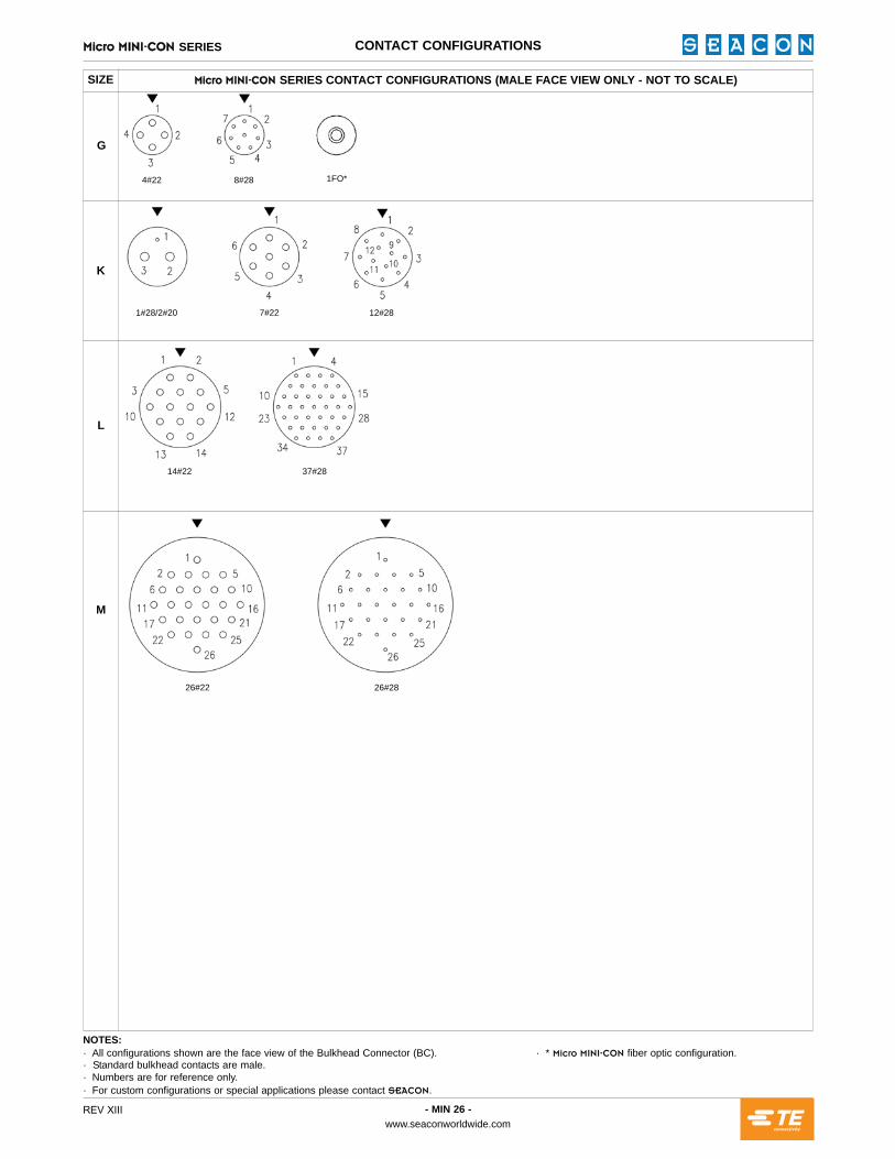
jáÅêç jfkfJ`̀lk SERIES CONTACT CONFIGURATIONS
G
K
L
M
NOTES:· All configurations shown are the face view of the Bulkhead Connector (BC). · * jáÅêç jfkfJ`lk fiber optic configuration.· Standard bulkhead contacts are male.· Numbers are for reference only.· For custom configurations or special applications please contact pb^`lk.
SIZE jáÅêç jfkfJ`̀lk SERIES CONTACT CONFIGURATIONS (MALE FACE VIEW ONLY - NOT TO SCALE)
4#22 8#28 1FO*
14#22
26#22 26#28
37#28
1#28/2#20 7#22 12#28

HANDLING PROCEDURES AND SPECIAL CAPABILITIES
Even though these procedures appear simple, only qualified techni-cians should perform the installation and maintenance. Connectors are designed for installation on one atmosphere vessels. Contact pb^`lk for recommendations if using compensated vessels.
INSTALLATION PROCEDURESTorque values referenced assume installation into dry metal threads. Bulkhead connector receptacle (BCR) o-ring should be lubricated with an appropriate silicone grease before installing. This lubricant should be applied to form an adequate film. Excessive lubrication is detrimen-tal to the operation of the connector. Care must be taken to ensure no grease or dirt is present on the face of the fiber optic contact. Cleaning of the contact is recommended using only suitable products. CCP o-ring should be greased as above with the same care being taken.
CARE AND MAINTENANCEOnce mated the connector requires no maintenance. When stored all fiber contacts should be protected with suitable dust caps. CAUTION: The use of some oil-based propellants in spray cans can cause conductivity problems in neoprene.
CABLE AND CONTINUITY PRESERVATIONAvoid sharp bends in cables. Cables subjected to vibration and exposed to seawater drag should be adequately clamped to prevent fatigue and possible failure.
SPECIAL ASSEMBLIESpb^`lk maintains all facilities necessary to furnish complete under-water and environmental electrical connector/cable systems, including Research and Development, Engineering, Manufacturing, Quality Control and Pressure Testing. As well as supplying our standard ‘off-the-shelf’ items, we have the capability to design and manufacture SPECIAL CUSTOMIZED CONNECTORS AND CABLE ASSEMBLIES to suit your individual needs.
All reasonable efforts have been taken to ensure that the information contained herein is accurate at the date of publication, but no representation or warranty as to the accuracy or completeness of such information is intended or to be implied by its inclusion herein. Any and all representations and warranties pertaining to the information and products referred to herein shall be set forth in pb^`lk standard sales order form. In addition, pb^`lk reserves the right to make changes to the contents hereof without notice, therefore it is suggested that at the time of inquiry, the appropriate sales office or factory be contacted directly for verification of published specifications and products availability.
© 2017 pb^`lkALL RIGHTS RESERVED
pb^`lk1700 Gillespie Way,El Cajon, California 92020, USA.TEL: +1 (619) 562-7071FAX: +1 (619) 562-9706E-Mail: [email protected]: www.seaconworldwide.com
pb^`lk US GULF AREA SALES OFFICE14511 Old Katy Road, Suite 300,Houston, Texas 77079, USA. TEL: +1 (281) 599-3509FAX: +1 (281) 599-3517E-Mail: [email protected]: www.seaconworldwide.com
pb^`lk US EAST COAST SALES OFFICETEL: +1 (401) 637-4952FAX: +1 (401) 637-4953E-Mail: [email protected]: www.seaconworldwide.com
pb^`lk ADVANCED PRODUCTS, LLC1321 Nelius Road, P.O. Box 767,Bellville, Texas 77418, USA.TEL: +1 (979) 865-8846FAX: +1 (979) 865-8859E-Mail: [email protected]: www.seacon-ap.com
pb^`lk BRAZILRua Conde de Bonfim 120 sala 212, Tijuca,Rio de Janeiro, Brazil, CEP: 20520-053.TEL: +55 011 2103-6263CELL: +55 021 97499-1270E-mail: [email protected]: www.seaconworldwide.com
pb^`lk (europe) LTDSeacon House, Hewett Road, Gapton Hall Industrial Estate,Great Yarmouth, Norfolk, NR31 0RB, UK.TEL: +44 (0) 1493-652733FAX: +44 (0) 1493-652840E-Mail: [email protected]: www.seaconeurope.com
pb^`lk GLOBAL PRODUCTIONBlvd. Paseo del Cucapah no. 16822-BColonia el Lago C.P. 22210Tijuana, BC MexicoTEL: +52 (664) 626-2726FAX: +52 (664) 686-8922E-Mail: [email protected]: www.seaconglobal.comDial from U.S.A. TEL: +1 (619) 308-7901TOLL FREE: (888) 562-7072FAX: +1 (619) 308-7900
pb^`lk PHOENIX15 Gray Lane, Suite 108, Hopkinton Industrial Park,Ashaway, Rhode Island 02804, USA.TEL: +1 (401) 637-4952 FAX: +1 (401) 637-4953E-Mail: [email protected]: www.seaconphoenix.com
REV XIII