jetc: joint energy thermal and cooling management for
TRANSCRIPT
JETC: Joint Energy Thermal and Cooling Management for Memory and CPUSubsystems in Servers
Raid Ayoub Rajib Nath Tajana RosingUniversity of California, San Diego
La Jolla, CA 92093-0404
Abstract
In this work we propose a joint energy, thermal andcooling management technique (JETC) that significantly re-duces per server cooling and memory energy costs. Ouranalysis shows that decoupling the optimization of coolingenergy of CPU & memory and the optimization of mem-ory energy leads to suboptimal solutions due to thermal de-pendencies between CPU and memory and non-linearity incooling energy. This motivates us to develop a holistic so-lution that integrates the energy, thermal and cooling man-agement to maximize energy savings with negligible per-formance hit. JETC considers thermal and power statesof CPU & memory, thermal coupling between them and fanspeed to arrive at energy efficient decisions. It has CPU andmemory actuators to implement its decisions. The memoryactuator reduces the energy of memory by performing cool-ing aware clustering of memory pages to a subset of mem-ory modules. The CPU actuator saves cooling energy byreducing the hot spots between and within the CPU socketsand minimizing the effects of thermal coupling. Our exper-imental results show that employing JETC results in 50.7%average energy reduction in cooling and memory subsys-tems with less than 0.3% performance overhead.
1. Introduction
Technology scaling coupled with the high demand forcomputation leads to a wide use of server systems with mul-tiple CPU sockets and larger amounts of memory resultingin higher power densities [1, 2]. High power dissipationincreases the operational costs of machines. It also causesthermal hot spots that have substantial effect on reliability,performance and leakage power [25, 7]. Dissipating the ex-cess heat is a big challenge as it requires a complex andenergy hungry cooling subsystems.
Traditionally, the CPU is known to be the primary sourceof system power consumption. Over the years the designershave developed techniques to improve the energy efficiency
of the CPU subsystem which accounts for approximately50% of the total energy budget. Less attention is given toenergy optimization in rest of the system components whichleads to a poor energy proportionality of the entire system[11]. Memory subsystem is the other major power hungrycomponent in the server systems as it consumes up to 35%of total system energy and has poor energy proportionality[10, 11]. Capacity and bandwidth of the memory subsystemare typically designed to handle the worst case scenarios.Applications vary significantly in terms of their access ratesto the memory. It is common that only a fraction of memorypages is active while the rest are dormant. One solution isto activate a subset of the memory modules that can servethe applications needs to save energy [18]. However, thisapproach increases the power density of the active memorymodules which can cause thermal problems in the memory.
In [21, 22], the authors proposed a solution to mitigatethermal emergencies in the memory system by adjustingmemory throughput to keep the memory temperature in thesafe zone. However, this solution does not improve energyproportionality in the memory subsystem since it does notconsider minimizing the number of active DIMMs to justwhat is needed. To manage thermal emergencies within asingle CPU socket, a number of core level dynamic ther-mal management (DTM) techniques have been proposed[15, 30]. The benefits of these techniques are limited tomanaging the temperature within a single socket. The im-portant issue is that none of the existing techniques considerthe dynamics of the cooling subsystem and its energy costs.
Modern servers incorporate a fan subsystem to reducetheir temperature. The power consumed by a fan is cubi-cally related to the air flow rate which makes it energy hun-gry [24]. The fan system in high-end servers consumes asmuch as 80 Watts in 1U rack servers [24] and 240 Wattsor more in 2U rack servers [1]. The cooling subsystembecomes inefficient when it operates far from the optimalpoint due to poor thermal distribution. Workload alloca-tion policies need to account for cooling characteristics tominimize cooling energy by creating a better thermal distri-bution. Due to cost and area constraints, a common set of

fans is normally used to cool both the CPUs and memory[2]. For such scenarios, the inlet temperature of the down-stream (components at the end of air flow path) become afunction of the temperature of the upstream (componentsat the entrance of air flow) in addition to the primary inlettemperature of the server. Energy optimization techniquesmust consider temperature constraints and cooling costs formaking intelligent decisions.
In this work we present JETC, a joint energy, thermal andcooling management algorithm for individual servers whichtargets the improvements in server power usage efficiency(SPUE) by dynamically reducing the cooling and memoryenergy costs. Providing an integrated solution is neces-sary due to the thermal dependencies between the CPU andmemory when both share same cooling resources. JETCmaximizes the energy efficiency in the server by control-ling the number of active memory modules to just what isneeded to provide sufficient storage capacity and bandwidthwhile minimizing the cooling costs. JETC also schedulesthe workload between the CPU sockets to create a more bal-anced thermal distribution between them not only to mini-mize the thermal coupling effect but also to mitigate theirthermal hot spots as well. Finally, we show that using JETCresults in 50.7% average energy reduction of memory andcooling subsystems with less than 0.3% performance over-head.
2. Related workIn recent years, energy and thermal management in
memory and CPU has become a vibrant research area. Theresearch in this domain can be classified broadly into threemain categories as follows:
Power and thermal management of memory subsystem:Recent research has sought a number of techniques to opti-mize the energy consumption in memory subsystems. Thework in [17] lowers DRAM power by changing memorymode to low power state when there are no accesses to thememory. This approach is beneficial only when there arefrequent idle periods. Research in [18] manages memorypower by clustering heavily accessed pages to a subset ofthe memory modules and putting the rest in a self-refreshmode. However, this consolidation is likely to generatethermal problems due to clustering. Both of these tech-niques do not consider any thermal issues.
To handle thermal problems in memory subsystem, a fewtechniques have been suggested [21, 20]. The work in [21]mitigates overheating in memory system by adjusting mem-ory throughput to stay below the emergency level. The pri-mary drawback of this approach is the associated perfor-mance overhead. Research in [20] manages memory over-heating by grouping threads in the system in such a waythat each group is mapped to a subset of memory modelsassuming that all the threads in a group can be active simul-
taneously. Only one group of memory models is active atany point in time while the rest stay inactive to cool. Theauthors assume that the bandwidth of each thread is knownin advance through static profiling which is normally notthe case in dynamic systems. Additionally, this approach isrestricted to the cases when number of threads is a multipleof the number of cores. The work in [23] proposes thermala management technique for the memory subsystem at themicroarchitectural level. This technique does not optimizefor number of active DIMMs to reduce energy. However,none of these techniques account for cooling energy whichcan be a significant portion of the system energy.
Thermal management of CPU subsystem: In recentyears, a number of core level thermal management tech-niques have been suggested. The research in [13] pro-poses two reactive DTM techniques. The first techniqueis based on dynamic voltage-frequency scaling while theother uses pipeline throttling to remove the excess heat.Recently, DTM has become an integral part of actual pro-cessor designs. For example, Intel Xeon processor em-ploys clock gating and dynamic voltage-scaling to managethermal emergencies. The research in [14, 19, 16] pro-poses activity migration to manage the excess temperatureby moving computations across replicated units. The draw-backs with all of these approaches are performance over-head and poor thermal distribution since they are reactivein nature. To overcome the problems with reactive tech-niques, a class of proactive thermal management techniqueshave been suggested that try to avoid the overheating whilethe processor is still running below the temperature thresh-old. The authors in [15] proposed a temperature predictionmodel that is based on the serial autocorrelation in the tem-perature time series data. Although their model is fairlyaccurate, it requires a run time training phase that couldimpact performance. In addition, all these techniques arelimited to a single CPU socket and do not model coolingdynamics which may have a significant effect on the tem-perature profile.
Cooling management: Recently, a few cooling algo-rithms have been suggested to optimize the fan controller[29, 26]. The research in [29] suggests an optimal fan speedmechanism for the blade servers that determines the optimalspeed through solving a convex optimization. The work in[26] designs a fan control mechanism that also considers theleakage power. A class of techniques have been suggestedto improve cooling efficiency at the data center level [28].These techniques suggest the use of workload scheduling tomitigate the air circulation problem in data centers. How-ever, they are not effective at the socket level since the airflow is highly contained within servers. In [24, 3] method-ologies are proposed to model the convective thermal re-sistance of the heat sink as a function of the air flow rate,which we use here.

In this work we make the following main contributions:• We present JETC, a novel integrated energy, thermal
and cooling management for memory and CPU sub-system to deliver high energy savings.
• We have developed a detailed memory thermal modelthat considers the cooling dynamics and thermal cou-pling with other hot spots in the system. This is the firstcomprehensive model that integrates the cooling dy-namics and thermal coupling between CPU and mem-ory subsystems.
• We present a thorough evaluation of the our techniquethat achieves 50.7% average energy savings in coolingand memory subsystems at performance overhead ofless than 0.3%.
3. Combined thermal and cooling model forCPU and memory
Figure 1(a) depicts the photo of our 45nm Intel QuadCore dual socket Xeon E5440 server where the CPU isplaced close to the fan while the memory is downstream[2]. Having a shared cooling resource creates thermal de-pendencies between the upstream and downstream compo-nents. This server supports two off-chip memory controllerswhere each is connected to memory by two memory chan-nels, each channel is connected to four dual in-line mem-ory modules (DIMMs) as shown in Figure 1(b), each isa 4GB DDR2. We measure power of individual DIMMswith data acquisition system by adding extenders that sup-port current sensors in the supply lines of each DIMM. Thespecifications of the CPU, memory and cooling subsystemsare given in Table 1. Benchmarks from the SPEC2000 suitehave been used as workloads.
3.1. System thermal model
Cooling systems use fans to generate air flow to reducethe temperature of hot components. In our dual socket sys-tem, the generated air flow passes through the heat sink ofthe CPU first and eventually reaches the memory DIMMs.This means that the memory and CPU are thermally con-nected as the CPU heats up the common air flow before itreaches the memory subsystem. As a result, the tempera-ture of the memory is a strong function of the hottest CPUand the inlet temperature.
Both cooling and thermals are modeled based on theknown duality between electricity and temperature [27].Cooling is commonly modeled through variable convectiveresistance, where its value is a function of the air flow rate[24]. The value of the convective resistance Rconv can becomputed as:
Rconv ∝ 1
AV α(1)
where A is the heat sink effective area, V is the air flowrate and α is a factor with a range of (0.8 - 1.0). For a
given heat flow, the smaller the value of Rconv, the lowerthe temperature. To estimate the power dissipation of fanwe use the results from [24] to relate the fan speed, F , withthe air flow rate as: V ∝ F . The cooling power costs forchanging the air flow rate from V1 to V2 can be computedas [24, 26]:
PV 2
PV 1= (
V2
V1)3 (2)
where PV 1 and PV 2 represent the fan’s power dissipationat V1 and V2 respectively. Figure 2 show the unified ther-mal/cooling model of both CPU and memory. We combineCPU and memory thermal model using dependent thermalcoupling heat sources to model the extra heat that is gener-ated by the upstream CPU. Definitions of CPU and memorythermal models are discussed in sections 3.2 & 3.3 respec-tively. The dependent coupling heat source of the memory,qD, is proportional to the heat sink temperature of the CPU,TCha, and inversely proportional to the thermal resistance of
the case to ambient of the memory DIMMs, RDca, as follows:
qD ∝ TCha
RDca
(3)
Experimental verification of thermal coupling: Wemeasure the temperature of the CPU heat sink which is lo-cated on the upstream of air flow using a thermal sensor. Atthe same time we measure the maximum junction tempera-ture of the memory using Intelligent Platform ManagementInterface (IPMI) to observe the correlation between heatsink temperature and that of memory. We also measure thepower of the DIMMs to account for temperature changesdue to power variations. For this experiments we use 4DIMMs, each connected to a single channel, where everytwo DIMMs are located after one CPU socket. We run a sin-gle threaded memory intensive workload from SPEC2000suite, swim, on a single socket followed by progressivelyadding a CPU intensive workload, perl, to the same socket.The rationale behind running swim is to keep the memorypower at the same level during the experiment. After awarm up period of 300 seconds we continue run swim alonefor 800 seconds and execute one instance of perl right afterthis period and we add additional instance of perl at time2000 seconds. During this experiment, we restart any fin-ished jobs. Figure 3 shows the temperatures of memory andthe CPU heat sink that are referenced to their values at theend of the warm up period. The results clearly show that arise in the heat sink temperature causes a rise in the mem-ory temperature due to the extra heat that is transfered tomemory.
3.2. CPU thermal and cooling model
Unlike memory DIMMs where each DIMM containsmultiple chips, the CPU socket usually has a single chip.However, the power distribution within the CPU socket isnot uniform (e.g. some cores may be active while others are

(a) Server machine
Memorycontroller
I
Memorycontroller
CPU
A
B
C
DII
CPU
Memory DIMMs
(b) System organization and cooling
Figure 1. Intel dual socket Xeon server
��������
����
������
������
���
���
���
���
������
������
������
������
����
������
������
��������
PD
r1R
T
. . . .
R
R
Css
v
lja
Cca
Pj
C C
C
C
CC
C caTC
C caD
TjD
NRchip
D
TjD
NRchip
D
1 2
haT C
RDca
q ~ D
Cj
C
Local ambient temperature
Thermalcoupling
DIMM heat spreader
CPU Heat sink
PD
r2
Memory DIMM
Rank 1 Rank 2
NCchipD
CPU socket
RD
caR
C
ca
Figure 2. Combined thermal model
Figure 3. Thermal coupling
idle). The left part of Figure 2 shows the thermal model ofthe CPU chip with a thermal package [8, 27]. The thermalmodel of the CPU includes the die and the heat spreader.RC
v is the die component’s vertical thermal resistance in-cluding the thermal interface resistance. The lateral heatflow between die components is modeled using a lateralthermal resistance RC
l , but its effect is negligible [19]. CCj
is the thermal capacitance of the components in the die. Thepower dissipated by individual components is modeled as aheat source, PC
j . RCs and CC
s refer to the thermal resistanceand capacitance of the heat spreader respectively.
The heat flow from the CPU case to local ambient (am-bient temperature is measured inside the server enclosure)is modeled as a combination of conduction and convectionheat transfers, [27]. The thermal conductive resistance ofthe heat sink is RC
hs. The convective part is modeled by aconvective resistance, RC
conv, connected in series with RChs
where their sum represents the case to ambient resistance,RC
ca. RCca is connected in parallel with the thermal capaci-
tance of the heat sink, CCca, to form a simple RC circuit. The
changes in RCconv with air flow is calculated using (1).
3.3. Memory thermal and cooling modelTypical DRAM subsystem is organized as an array of
multiple DIMMs (see Figure 1(b)), where each DIMM iscomposed of ranks, usually 2, and each rank contains mul-tiple memory chips (e.g. 8 chips per rank). Each DRAMchip in a rank stores data that belongs to a predeterminedsegment of bits in the data word. As a result, the rank poweris distributed almost equally across the DRAM chips insidethe rank. To enhance the heat transfer between the DRAMchips and local ambient the DIMMs have a heat spreader.
The right part of Figure 2 shows the thermal model of aDIMM that uses a heat spreader. We use superposition the-ory to simplify the RC network of the DRAM chips of eachrank to a single RC node. In this Figure, the heat sourcePDchip equals to the power dissipated in each DRAM chip,
RDchip is the vertical thermal resistance of each chip, CD
chip
is the thermal capacitance of each chip and, TDj is the junc-
tion temperature of a DRAM chip. The number of DRAMchips in each rank is assumed to be N .
The heat transfer between the heat spreader and localambient is modeled as an RC node as shown in Figure 2.The thermal capacitance between the heat spreader and am-bient is represented by CD
ca. The value of RDs represents
thermal resistance of the heat spreader. The heat transferbetween the heat spreader and the interior ambient of themachine is modeled by a convective resistor, RD
conv. Thecomponent RD
ca corresponds to the case to ambient ther-mal resistance (RD
ca = RDs +RD
conv). The time constant ofheat spreader is in the range of tens of seconds [21] whilethe time constant for the DRAM chip die is in the orderof tens of milliseconds [27]. This means that the transient

Time (sec)
Tempe
rature
rise
(deg
reeC)
2swim: 4 DIMM
2swim: 8 DIMM
2mcf: 4 DIMM
2mcf: 8 DIMM
RC model
Figure 4. DIMM’s transient temperature (ref-erenced to idle temperature)
behavior of the junction temperature is dominated by theheat spreader temperature dynamics over the long run asthe DRAM chip temperature reaches steady-state quickly.We exploit the big differences in time constants to reducethe thermal model complexity. We can simplify the modelfurther by assuming that the power across ranks is similarsince the memory controller uses interleaving to uniformlydistribute the activities across the DIMMs as well as theirranks, nr. The junction temperature of a given rank can bemodeled as:
dTDj (t)
dt= −
TDj (t)
τDca+
γ
CDca
(PD +qD
γ) (4)
where γ = (1 +RD
j
RDca) and RD
j =RD
chip
Nnr. The term PD
represents the total power dissipated in the DIMM and τDcais the time constant of the heat spreader component whichequals to CD
caRDca.
Experimental verification of DIMM thermal modelWe run memory intensive benchmarks, swim and mcf fromSPEC2K, and collected the DIMMs junction temperaturetraces using IPMI. Figure 4 shows the temperature tracesof 4 DIMMs and 8 DIMMs configurations to show that ourmodel is not limited to a specific setup. The 4 DIMMs and 8DIMMs are placed in the memory slots following the order,(A1, B1, C1, D1) and (A1, A2, B1, B2, C1, C2, D1, D2) re-spectively as shown in Figure 1(b). The fan speed is set tomaximum using boost mode option to keep the time con-stant of the heat spreader of the memory modules constant.The figure shows clearly that the DIMM temperature dy-namics is dominated by the heat spreader temperature sinceit changes slowly, with a time constant of 70 seconds. Weplotted the transient temperature of the RC model and com-pared it with the actual temperature readings to show thatthe case to ambient temperature changes can be modeledusing a single RC node as shown in Figure 4. The resultsshow a strong match between the actual and ideal modelwith average error of 0.27oC relative to the real measure-ments.
3.4. Sources of energy savings in memoryThe DRAM energy consumed to do the actual job of
reading or writing data is only a fraction of the total DRAM
energy. This is because DIMMs consume energy to keepstate of the stored information and to provide sufficient re-sponsiveness to the incoming requests [18]. We can saveenergy by consolidating the active memory pages of theworkload into a smaller set of DIMMs and place the restin a self-refresh mode [18].
Figure 5 shows the impact of consolidation on power perDIMM (The number in front of the benchmark refers to thenumber of instances we run). In this experiment we balancethe workload across the two sockets. In the first configu-ration, we use four DIMMs where each is connected to aseparate memory channel to maximize bandwidth. For thesecond case, we use eight DIMMs with two DIMMs perchannel. We can achieve 16Watts savings with this consoli-dation, higher savings can be delivered when the system hasmore DIMMs. The power is not decreased to half in the caseof eight DIMMs which indicates that a fraction of the mem-ory power is used to keep the DIMMs functional, whichwe call baseline power. The savings are higher for mem-ory intensive workloads (swim, equake, mcf ) compared toCPU intensive ones (eon, gzip, perl, bzip2, gcc) as expected.However, this consolidation increases the power density byup to 33% which can elevate the temperature problems.
Next we address the impact of consolidation on perfor-mance. We run experiments on our machine with differ-ent DIMMs organizations as follows: single DIMM, twoDIMMs and four DIMMs (each DIMM is connected to aseparate memory channel) and eight DIMMs (every twoDIMMs are connected to a separate memory channel). Fig-ure 6 shows the effect of DIMM consolidation on perfor-mance compared to a system with eight DIMMs. For thecase of using one and two DIMMs the performance degra-dation is noticeable since only a fraction of the bandwidth isutilized. However, when we fully utilize the memory band-width (as in the case of four DIMMs) the resultant perfor-mance is close to the baseline case. This slight improve-ment in the case of eight DIMMs compared to four DIMMsis related to the reduction in bank conflicts as we are addingmore banks. Nevertheless, this improvement is small sincethe number of pages (usually order of thousands or more)is much larger than the number of banks (order of tens).Hence, little improvement in temporal locality can be at-tained. This indicates that the performance overhead due toconsolidation is in the acceptable range assuming the mem-
1-gcc
2-gcc4-gcc
1-bzip2
2-bzip2
4-bzip2
1-perl
2-perl
4-perl
1-gzip
2-gzip
4-gzip1-eon
2-eon
4-eon
1-swim
2-swim
4-swim
1-equake
2-equake
4-equake
1-mcf
2-mcf
4-mcf
1
2
4
Memory
powerperDIM
M(W
att)
4 DIMM
8 DIMM
Figure 5. Memory power per DIMM

(a) mcf (memory bound) (b) equake (memory bound) (c) bzip2 (CPU bound)Figure 7. Memory page access pattern
1_swim1_bzip2 1_gzip 1_eon1_equ
ake1_mcf 1_perl 3_swim3_bzip2 3_gzip 3_eon3_equ
ake3_mcf 3_perl AVG
1
1
2
2
3
3
Perform
ancereduction(%
) 1 DIMM
2 DIMMs: 1 DIMM per channel, 2 mem controllers
4 DIMM: 1 DIMM per channel, 2 mem controllers
Figure 6. Performance with consolidation
ory pages can fit in the consolidated DIMMs.To ensure the page migration policy is beneficial, we
need to have fast and energy efficient migrations. Figures7(a), 7(b), 7(c) show the page access patterns of mem-ory and CPU intensive applications. We use M5 a micro-architectural simulator [12], to generate these statistics. Wesimulate for a representative period of 15 billion instruc-tions of each benchmark. Each graph shows the accessdistribution for half and full of the simulated interval toexamine the changes in the access pattern. These resultsshow that the number of active pages (hot pages) is a smallfraction of the total number of pages of the application. Ingeneral, it is likely we can capture sufficient number of hotpages to migrate during execution quickly enough to resolvethermal emergencies.
4. Joint energy, thermal and cooling manage-ment
Our joint energy, thermal and cooling management formemory-CPU subsystems, JETC, is shown in Figure 8(a).It consists of JETC controller, two actuators (memory andCPU) and sensors (temperature and power). On each de-cision tick the controller analyzes the data provided by thesensors to arrive at appropriate decisions for actuators toimplement. The decision takes into account thermal depen-dencies between CPU sockets and memory. The JETC’scontroller is implemented in the operating system layer.
JETC’s controller: Figure 8(b) shows the details ofJETC’s controller. JETC actions are modeled using a statemachine with four discrete states: Smc, Sc, Sm, and Si, tohandle four distinct control scenarios of memory, CPU and
fan speed. The transitions between states are triggered as afunction of fan speed, temperature (CPU and memory) andthe number of active DIMMs.
JETC activates only the CPU actuator (State Sc) whenthere are thermal problems in CPU subsystem but no ther-mal problems in the memory. It activates only the mem-ory actuator (State Sm) when there are thermal problemsin memory subsystem but no thermal problems in the CPUsubsystem. When there are no thermal problems in the sys-tem and fans are balanced then JETC does not need to act soit can stay in the idle state (State Si). In this state, no socketor memory page scheduling is performed and the number ofactive DIMMs is set to the default DIMM clustering size.This default size is defined as the minimum number of ac-tive DIMMs (ND
min), in general one DIMM per memorychannel to maximize bandwidth.
State Smc: This state handles the cases when there is aneed of a joint action from CPU and memory actuators tomitigate thermal problems. The difference in heat genera-tion between CPU sockets can lead to imbalance in speedof fans which is a source of energy inefficiency in the sys-tem due to the cubic relation between fan power and speed.This difference in heat generation disturbs the thermal dis-tribution of memory due to the thermal coupling that maylead to imbalance in speed of fans. A transition to Smc hap-pens in any of the following scenarios: 1) imbalanced fanspeed with thermal problems in memory (high temperatureor number of active DIMMs is higher than default), 2) tem-perature exceeds threshold in both CPU and memory.
When there is an imbalance in speed of fans, JETC acti-vates the CPU actuator to perform socket level schedulingto minimize the difference in heat generation between CPUsockets by migrating workload from a hot CPU to a coolerone. This helps balance the temperature across the memorymodules. The CPU actuator also runs core level thermalmanagement to minimize the temperature within the CPUs[9]. At the same time, the Memory actuator performs en-ergy aware thermal management by activating just what isnecessary of memory modules to meet thermal and perfor-mance constraints.
CPU actuator: The details of the CPU scheduler are givenin Algorithm 1. CPU scheduling can reduce the cooling en-

Memory subsystem
DIMM
Core1 . . . .Core2 Core1 CoreN. . . .Core2Thermalsensors
CoreNThermal
Temperatureprediction
Temperatureprediction
sensors
Core
. . .
Core
CPU socket 1 CPU socket M
Memory page scheduling
scheduling
Power & thermalsensors and fan speed
CPU socket
scheduler scheduler
JETC controller
Fan controller
Fan subsystem
Thermal sensors
(a) Architecture
+
0000
01x0
0000
01x0 00
00
01x0
, 0x1
0
Memory actuator
Memory actuator
Socket actuator
x1x1, 11xx
11xx, x1x1
x1x1, 11xxS S
S
i m
mc
xx11, 1x1x
Sc
Socket actuator
No management
100x, x001100x, x001
100x
, x00
1
(b) JETC’s controller
Figure 8. Architecture and controller of JETC. Each edge denotes a transition annotated with a com-pound condition of 4 bits. Bit-1 (LSB) is true when CPU’s temperature is high. Bit-2 is true whenmemory temperature is high. Bit-3 is true when the number of active DIMMs is larger than the de-fault value. Bit-4 is true when there is a fan speed imbalance. The x-mark denotes a don’t care.
ergy of the memory by creating a balanced thermal distribu-tion in memory since CPU and memory are thermally con-nected. In step 1, the CPU actuator calculates the vector,ΔPC , of the desired change in power values in each of theCPUs to balance fan speed and to reduce the cooling energyof the memory subsystem. The elements of the vectorΔPC
are computed as follows:
ΔPCi =
PCi ΔRC
cai
Rcai ± |ΔRCcai
| (5)
where ΔRcai = (Fi − Fr)dRca(Fi)
dF , Fi is the fan speedassociated with socket i and Fr is the target fan speed (av-erage of speed of fans in the system). The value of PC
i
corresponds to the socket power and the (+,−) signs in thedenominator correspond to the source (hot) and destination(cold) CPUs respectively. The actuator also estimates thepower consumed by the individual threads in each CPU bymodeling their core and last level cache power that is basedon instruction per cycle (IPC), leakage power and cache ac-cess rate [8]. The total socket power can be estimated usingpower dissipation counters in hardware [4].
Our algorithm in steps 2-17 traverses the workload andspreads the threads from the hot CPU starting with coolerthreads to have a finer grain control of the total power oneach socket and to reduce the chance of errors. This algo-rithm removes from a hot CPU (CPUi) a number of threadsthat have total power that is less than or equal to |ΔPC
i |.The cool CPU (CPUj) receives threads with a total powerthat is less than or equal to |ΔPC
j |. Before each migra-tion we evaluate the cooling energy savings to prevent inef-fective scheduling decisions. Individual scheduling eventsare allowed only when the predicted cooling savings arehigher than a given threshold, Smin. Cooling savings dueto the temperature change in CPUs are estimated as in [8].
The temperature change in the DIMMs is calculated using:ΔTD = λδPC
i RCcai
where δPCi is the estimated change in
power of the upstream CPU due to thread migration and λis the thermal coupling factor. The corresponding change infan speed is calculated using (8).
Algorithm 1 Socket level scheduling1: Calculate ΔPC and the set of PC
thr for each CPU. Set Q as an empty queue2: for i in set of hot CPUs do3: for j in unmarked threads in CPU i do4: dest ⇐ index of coolest CPU5: if (PC
thrj≤ |ΔPC
i | and PCthrj
≤ |ΔPCdest|) then
6: if CPU dest has an idle core then7: Calculate cooling savings of migrating thread j to CPU dest8: else9: Calculate cooling savings of swapping thread j with the coolest
thread from CPU dest10: end if11: if cooling savings > Smin then12: Enqueue this migration in Q13: Update ΔPC and threads assignment14: end if15: end if16: end for17: end for18: Execute migration events in Q
Memory actuator: This actuator keeps the temperature ofmemory modules within the safe zone while minimizing en-ergy. It also accounts for fan speed and CPU heat genera-tion since they affect the memory temperature. This actu-ator may need to either increase or decrease the DIMMspower dissipation using page migration knob when possi-ble. However, when temperature is high and there are noactive DIMMs that can accept additional pages, then wechoose between activating a new DIMM or letting the fanspin up to cool the DIMMs. We decide between these twooptions based on the temperature reduction each choice candeliver under the same energy budget. Next we study thesescenarios.

1-swim-4DIMM
1-swim-8DIMM
2-swim-4DIMM
2-swim-8DIMM
4-swim-4DIMM
4-swim-8DIMM
1-equake-4DIMM
1-equake-8DIMM
2-equake-4DIMM
2-equake-8DIMM
4-equake-4DIMM
4-equake-8DIMM
1-mcf-4DIMM
1-mcf-8DIMM
2-mcf-4DIMM
2-mcf-8DIMM
4-mcf-4DIMM
4-mcf-8DIMM
1
2
4
8
PerDIMM
power(W
att)
Baseline
Dynamic
Figure 9. DIMM power breakdown
A. Increasing fan speed versus activating a new DIMM: Fig-ure 9 shows that doubling the number of DIMMs does notreduce the power per DIMM to half. This is due to the base-line power Pbase component that is in the range of 3.5 Wfor memory bound applications measured on 4GB DDR2DIMMs. This means that increasing the fan speed may be abetter option if it results in a lower temperature at powerconsumption of Pbase. Increasing fan speed reduces thememory temperature by lowering its convective resistanceas well as the effect of thermal coupling as the temperatureof the upstream CPU reduces too. The temperature reduc-tion for increase in fan power by Pbase can be computedusing our thermal model as:
ΔTfan = ΔF (λPCact
dRCconv(F )
dF+ PD
act
dRDconv(F )
dF) (6)
where ΔF is the increase in fan speed of the hottest mem-ory zone. PC
act and PDact correspond to the CPU and hottest
DIMM power that is located in the CPU zone respectively.When the actuator decides to activate a new DIMM, itmigrates pages from other DIMMs to the newly activatedDIMM progressively from the application starting with theone that has the highest memory access to reduce powerdensity. Using our thermal model, the temperature reduc-tion, |ΔTmem|, for adding one more DIMM can be com-puted as:
ΔTmem =(TD
jmax− PbaseR
Dca − λTC
ha)
nD(7)
where nD is the number of DIMMs after expansion and λis the thermal coupling factor between CPU and memory.The TD
jmaxis the maximum temperature of the DIMMs. The
controller choses to activate a new DIMM only if the tem-perature reduction, |ΔTmem|, is higher than |ΔTfan| whena new DIMM is activated, as follows:
if(|ΔTfan| < |ΔTmem|) ⇒ activate a new DIMM
else ⇒ increase fan speed(8)
B. Controlling DIMMs power by page migration: Whentemperature is high in subset of DIMMs, the actuator mi-grate pages from these DIMMs to the ones that can acceptsmore pages until the temperature drops to the safe zone. Theother scenario is when all active memory modules can ac-cept more pages (cold DIMMs), the actuator migrates pages
Table 1. Design parameters
CPU
CPU Xeon E5440TDP 80W
CPU frequency 2.8GHzHeat spreader thickness 1.5mmCase to ambient thermal RC
ca = 0.141 + 1.23V 0.923
resistance in K/W V : air flow (CFM) [3]Heat sink time constant at 25 seconds
max air flowTemperature Threshold 90oC [24]
DIMM
DIMM size 4GBMax DRAM power/DIMM 10W
Case to ambient thermal RDca = 0.75 + 45
V 0.9
resistance in K/W V : air flow (CFM)Chip thermal resistance in K/W RD
chip = 4.0 [5]Heat spreader time constant 70 seconds
at max air flowTemperature Threshold 85oC [21, 20]
Self refresh power per DIMM 0.15WThermal coupling factor 0.65
with CPU
Fan
Fan power per socket 29.4 W [6]Max air flow rate per socket 53.4 CFM [6]
Fan steps 32Fan sampling interval 1 second
Idle fan speed 10% of max speed
from the most recently activated module to the rest so thatit can be placed in a low power mode when no active pagesare left. The actuator maximizes performance by migrat-ing pages to a memory module only if it has lower mem-ory access rate and lower power consumption than the av-erage values. In this way, all the accesses are uniformlydistributed among the active memory modules. To mini-mize hot spots, the controller balances the number of activeDIMMs per CPU zone (CPU and its associated downstreamDIMMs). For example, the activation order of DIMMsshown in Figure 1(b) should be Ai, Bi, Ci, Di, Ai+1, Bi+1
etc. The page migration continues until the access rate ofthe newly activated DIMM becomes equal to that of alreadyactive DIMMs. Whenever a page is migrated from DIMMi
to DIMMj , the virtual to physical address mapping for thepage is updated in the page table of the operating system.The overhead of migrating pages is acceptable since thedifference between the temperature time constant and pagemigration time is over 6 orders of magnitude.
5 Evaluation
5.1 Methodology
In this paper we run the workload in our server and col-lect real power traces from the memory modules. Thesepower traces are used to estimate temperature using our ex-tended version of the HotSpot simulator [27]. We also mea-sure the CPU core, L2 and baseline power using the methoddescribed in [8]. The core and L2 power traces are usedto estimate the core and L2 temperatures respectively us-ing HotSpot simulator and Xeon processor layout. We alsoinclude the baseline power of the CPU in the temperaturesimulations.
The memory organization is assumed to be similar to ourIntel server (see Figure 1(b)). The memory controller putsthe inactive DIMMs in a self-refresh mode and the rest inthe active mode. Power consumption during self-refresh isgiven in Table 1. We use M5 simulator to generate the pageaccess statistics of the applications [12]. Whenever a page ismigrated to a different DIMM the virtual to physical addressmapping for the page is updated in the page table.
The characteristics of the fan and thermal package ofboth CPU and memory DIMMs that we use in thermal sim-ulation are listed in Table 1. For the fan control algorithmwe assume a closed loop PI (Proportional and Integral) con-troller that is usually used in modern systems. In our setupeach fan is controlled individually depending on the tem-perature of its associated CPU and memory modules. Weset the fan to trigger 5 degrees below the thermal thresholdof the chip (please refer to Table 1) to allow for enough timeto react to thermal emergencies.
For the memory and socket level thermal managers weset the scheduling interval to 4 seconds, since the thermaltime constant of both CPU and memory is on the orderof tens of seconds. Our technique is not restricted to thisinterval and other intervals around this value can be used.The interval of fan interval is set to 1 second so as to allowfor a detailed control over temperature to ensure reliability.We also set the cooling savings threshold to a conservativevalue of 10%. For core level thermal management policy,we employ the previously proposed proactive thermal man-agement which perform thermal aware core level schedul-ing at each OS tick [9].
A set of benchmarks are selected that exhibits variouslevels of CPU intensity to emulate real life applications (seeTable 2). We run each benchmark in the work set till itscompletion and repeat it until the end of simulation time.The evaluation time for our algorithms is set to 10 minutesafter the warm-up period. In our experiments we use a setof workloads that have a representative mix of CPU andmemory bound applications. The list of the workload com-binations that we use is given in Table 3.
JETC does an integrated energy, thermal and coolingmanagement for CPU and memory. Depending upon thestate of the system, JETC takes a coordinated action whichis a combination of CPU scheduling and memory thermaland power management. We evaluate JETC against the fol-lowing set of policies:
Dynamic Load Balancing (DLB): This policy is usuallyimplemented in modern operating systems which performsthread migration to minimize the difference in task queuelengths of the individual cores [14]. The balancing thresh-old is set to one to make the difference in task queue lengthequal to zero as possible. In this work we implement theDLB as our default policy for the purposes of comparison.This policy keeps all memory modules active. When the
temperature of CPU or memory exceeds the threshold, theiractivity is throttled progressively depending upon the sourceof the problem. This throttling is included in all the policies.
Dynamic Thermal Management of Core and Memorywith PI fan control (DTM-CM+PI): This policy implementsstate of the art thermal management techniques which op-erate separately from each other. The core policy forecastsdynamically the temperature of the cores and migrates thethreads from the hot to the cooler cores when it is possibleto create a more balanced thermal distribution [9]. Mem-ory thermal problems are managed by halting the accesseswhen the temperature exceeds thermal emergency level un-til it drops to the safe zone [21, 22]. All memory modulesstay active in this policy.
No Fan-Memory Optimization (NFMO): This policy islike JETC except that we disable the actuator that performsthe trade off between activating a new memory module andincreasing the fan speed. We choose this policy to evaluatethe impact of deactivating this optimization on the overallsavings. The minimum number of active DIMMs is set justas in JETC.
No Memory Management (NMM): This policy is likeJETC except all memory modules remain active the entiretime. The purpose of this policy is to evaluate the savingsthat we can achieved with minimizing thermal hot spots andoptimizing the cooling costs in the CPU subsystem only.
No CPU Migration (NCM): This policy disables theCPU management (socket and core scheduling) from JETC.We study NCM to show the impact of deactivating CPUpolicy on the overall cooling energy savings. The minimumnumber of active DIMMs is set as in JETC.
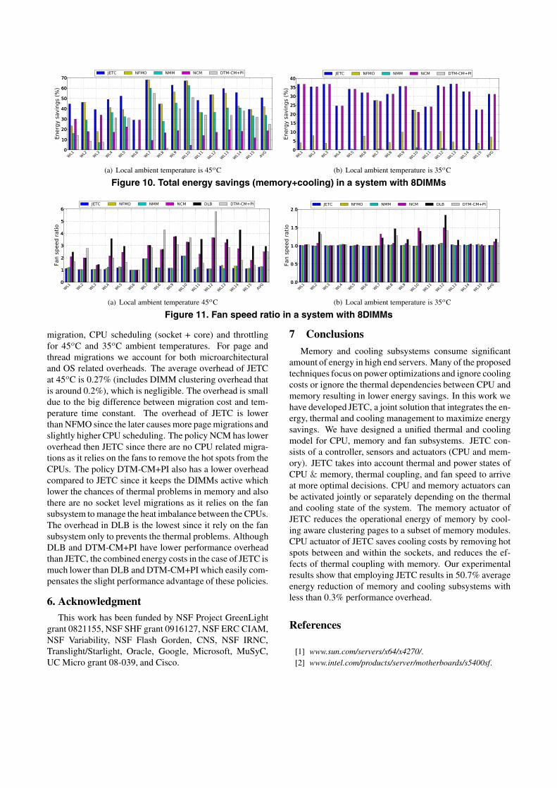
5.2 ResultsEnergy savings: Figure 10(a) show the total energy sav-ings in a system that has 8 DIMMs with 45oC local serverambient temperature. Our energy calculations include totalenergy of memory subsystem and cooling. JETC deliverssavings reaching an average of 50.7% and 25.49% relativeto DLB and DTM-CM+PI respectively. The results clearlyshow that JETC outperforms all other policies. For exam-ple, the case of workload W6 includes two mcf workload(memory bound), one on each socket, hence they producecomparable amount of heat in each socket and their thermalcoupling effect on the memory is comparable. The JETCsavings in this case come from clustering the memory ac-cesses to a smaller number of DIMMs since the thermaldistribution across the sockets is balanced and there are nothermal problems in the CPUs. The policy NCM performsequally well to JETC since it optimizes for memory andthere are virtually no savings opportunities from CPU ther-mal management. The policies NMM and DTM-CM+PIdeliver almost no savings since they do not optimize formemory energy. On the other hand, the savings opportuni-

Table 2. SPEC Benchmarks characteristicsBenchmark IPC Power per DIMM (Watt) Characteristics Benchmark IPC Power per DIMM (Watt) Characteristics
swim 0.55 4.65 Memory bound bzip2 1.36 1.18 CPU boundequake 0.51 4.38 Memory bound gcc 1.23 1.17 CPU bound
mcf 0.18 3.71 Memory bound eon 1.33 0.79 CPU boundperl 2.18 1.21 CPU bound gzip 1.16 0.92 CPU bound
Table 3. Workload combinations for multi-tier algorithmWorkload Socket A Socket B Workload Socket A Socket B
W1 equake + 2gzip 3bzip2 W9 mcf + 2gcc perl + bzip2 + eonW2 2bzip2 + 2eon mcf + gcc + 2gzip W10 3gzip 2perl + eonW3 equake + 2bzip2 2gzip + gcc W11 2equake + gcc 2perl + equakeW4 perl + eon + bzip2 2equake + gcc W12 mcf + 2gcc 2gcc + 2perlW5 2gcc + perl swim + 2gcc W13 gcc + 2perl equake + 2gccW6 mcf mcf W14 2mcf + gcc 2perl + mcfW7 gcc + 2gzip 2bzip2 + perl W15 2swim + gcc 2perl + swimW8 perl + bzip2 + 2eon 2mcf + 2gcc
ties for the cases of W7 and W10 are mainly related to im-balance in the thermal distribution between and within thetwo CPU sockets which raise cooling energy costs. JETCperforms quite well since it has the capability to balancethe temperature between and within the CPU sockets. Thepolicies NFMO and NMM perform equally well to JETCsince they balance socket and core temperatures. On theother hand, DTM-CM+PI delivers a fraction of the JETCsavings since it performs only local thermal optimizations.The policy NCM does not perform well since it only lowersmemory energy. The other important scenario is when thereare savings opportunities for minimizing memory energyconsumption and reducing CPU temperature imbalance asshown in W4 and W5.
Figure 10(b) shows the combined memory and coolingenergy savings with local ambient temperature of 35oC.JETC achieved savings reaching an average of 31% rela-tive to both DLB and DTM-CM+PI. In general, the savingsare lower than the case of 45o ambient temperature becausemost of the savings come from memory clustering as thesystem requires less cooling. The evidence of this can beseen from the savings of NMM and DTM-CM+PI policieswhich are close to zero while NCM perform closer to JETC.The JETC policy is able to perform well since it can capturethis class of savings opportunities by clustering the memoryaccess to a smaller set of DIMMs. These results also illus-trate the benefits of the optimization that trade off betweenactivating a new DIMM and speeding up the fan. The evi-dence of this benefit can be indicated from the low savingsof NFMO since it does not perform this optimization. Sincemost of the savings come from clustering the memory mod-ules then we expect that the savings would be lower whenthe workload exercises memory lightly. The cases of W7and W10 illustrate this scenario.Fan balancing: Next we evaluate the effectiveness of thesocket level scheduling in balancing the fan speed to mini-mize cooling energy where the optimal fan speed ratio be-tween the two sockets equal to 1. Figure 11(a) shows fanspeed ratio in a system with 8 DIMMs and 45oC local am-
bient temperature. The results show that JETC is able toreduce the standard deviation from the optimal fan speedratio by 62% compared to the DLB policy. The reason thatDLB has a high standard deviation from the optimal fanspeed is because it does not account for heterogeneity in theworkload in terms of the induced heat in the CPUs. The pol-icy DTM-CM+PI does not balance the temperature betweenCPU sockets resulting in a smaller effect on balancing fanspeed. The fan imbalance with this policy can be evenhigher than DLB (e.g W8 and W12). This scenario occurswhen core level scheduling is effective in one socket while itis not as effective in the other one (e.g. running CPU inten-sive workload). This increases the imbalance as the speedof one fan can be lowered while the other stays almost thesame. The other polices that implements socket level ther-mal balancing perform close to JETC. Figure 11(b) showsthe fan speed ratio in a system with 8 DIMMS and 35oCambient temperature. The reduction in standard deviationto the optimal target in this case is 94%.Page migration: We computed page migration per sec-ond to show the robustness of our solution. Figure 12(a)shows the rate of page migration in a system with 8 DIMMsand 45oC ambient temperature. The results show that JETCaverage rate of page migrations is below 5 pages per sec-ond. This overhead is negligible in practice since migratinga page takes a few microseconds which makes our solutionhighly attractive. Furthermore, having a few migrations isan indication that our solution is stable. The NFMO has thehighest migration rate since it may activate more DIMMsas it does not consider the trade off between fan speed andnumber of active DIMMs. The case of W15 has the high-est migration rate since the workload mix has 3 instances ofswim, swim has a wide set of hot pages. The page migrationrate for the system with 8 DIMMs and 35oC ambient tem-perature is shown in Figure12(b). In this case, the migra-tion rate for JETC drops below one page per second whichcauses almost no overhead.Overhead: Table 4 shows the performance overheadbreakdown for the entire set of workloads that includes page
WL1
WL2
WL3
WL4
WL5
WL6
WL7
WL8
WL9
WL10
WL11
WL12
WL13
WL14
WL15
AVG
0
10
20
30
40
50
60
70
Energysavings(%
)
JETC NFMO NMM NCM DTM-CM+PI
(a) Local ambient temperature is 45oC
WL1
WL2
WL3
WL4
WL5
WL6
WL7
WL8
WL9
WL10
WL11
WL12
WL13
WL14
WL15
AVG
0
5
10
15
20
25
30
35
40
Energysavings(%
)
JETC NFMO NMM NCM DTM-CM+PI
(b) Local ambient temperature is 35oC
Figure 10. Total energy savings (memory+cooling) in a system with 8DIMMs
WL1
WL2
WL3
WL4
WL5
WL6
WL7
WL8
WL9
WL10
WL11
WL12
WL13
WL14
WL15
AVG
0
1
2
3
4
5
6
Fanspeedratio
JETC NFMO NMM NCM DLB DTM-CM+PI
(a) Local ambient temperature 45oC
WL1
WL2
WL3
WL4
WL5
WL6
WL7
WL8
WL9
WL10
WL11
WL12
WL13
WL14
WL15
AVG
0 0
0 5
1 0
1 5
2 0
Fanspeedratio
JETC NFMO NMM NCM DLB DTM-CM+PI
(b) Local ambient temperature is 35oC
Figure 11. Fan speed ratio in a system with 8DIMMs
migration, CPU scheduling (socket + core) and throttlingfor 45oC and 35oC ambient temperatures. For page andthread migrations we account for both microarchitecturaland OS related overheads. The average overhead of JETCat 45oC is 0.27% (includes DIMM clustering overhead thatis around 0.2%), which is negligible. The overhead is smalldue to the big difference between migration cost and tem-perature time constant. The overhead of JETC is lowerthan NFMO since the later causes more page migrations andslightly higher CPU scheduling. The policy NCM has loweroverhead then JETC since there are no CPU related migra-tions as it relies on the fans to remove the hot spots from theCPUs. The policy DTM-CM+PI also has a lower overheadcompared to JETC since it keeps the DIMMs active whichlower the chances of thermal problems in memory and alsothere are no socket level migrations as it relies on the fansubsystem to manage the heat imbalance between the CPUs.The overhead in DLB is the lowest since it rely on the fansubsystem only to prevents the thermal problems. AlthoughDLB and DTM-CM+PI have lower performance overheadthan JETC, the combined energy costs in the case of JETC ismuch lower than DLB and DTM-CM+PI which easily com-pensates the slight performance advantage of these policies.
6. AcknowledgmentThis work has been funded by NSF Project GreenLight
grant 0821155, NSF SHF grant 0916127, NSF ERC CIAM,NSF Variability, NSF Flash Gorden, CNS, NSF IRNC,Translight/Starlight, Oracle, Google, Microsoft, MuSyC,UC Micro grant 08-039, and Cisco.
7 Conclusions
Memory and cooling subsystems consume significantamount of energy in high end servers. Many of the proposedtechniques focus on power optimizations and ignore coolingcosts or ignore the thermal dependencies between CPU andmemory resulting in lower energy savings. In this work wehave developed JETC, a joint solution that integrates the en-ergy, thermal and cooling management to maximize energysavings. We have designed a unified thermal and coolingmodel for CPU, memory and fan subsystems. JETC con-sists of a controller, sensors and actuators (CPU and mem-ory). JETC takes into account thermal and power states ofCPU & memory, thermal coupling, and fan speed to arriveat more optimal decisions. CPU and memory actuators canbe activated jointly or separately depending on the thermaland cooling state of the system. The memory actuator ofJETC reduces the operational energy of memory by cool-ing aware clustering pages to a subset of memory modules.CPU actuator of JETC saves cooling costs by removing hotspots between and within the sockets, and reduces the ef-fects of thermal coupling with memory. Our experimentalresults show that employing JETC results in 50.7% averageenergy reduction of memory and cooling subsystems withless than 0.3% performance overhead.
References
[1] www.sun.com/servers/x64/x4270/.[2] www.intel.com/products/server/motherboards/s5400sf.

WL1
WL2
WL3
WL4
WL5
WL6
WL7
WL8
WL9
WL10
WL11
WL12
WL13
WL14
WL15
AVG
0
5
10
15
20
25
30
35
40
45
Pagemigrationpersecond
JETC NFMO NCM
(a) Local ambient temperature 45oC
WL1
WL2
WL3
WL4
WL5
WL6
WL7
WL8
WL9
WL10
WL11
WL12
WL13
WL14
WL15
AVG
0
10
20
30
40
50
60
70
80
Pagemigrationpersecond
JETC NFMO NCM
(b) Local ambient temperature is 35oC
Figure 12. Page migration in a system with 8DIMMs
Table 4. Performance overhead (%)Local ambient Overhead JETC NFMO NMM NCM DLB DTM-CM+PItemperature source
45oC CPU scheduling 0.0552 0.0642 0.0731 - - 0.067345oC Page migration 0.0002 0.0005 - 0.0001 - -45oC Throttling 0.0161 0.0173 0.0254 0.0012 0.0011 0.0022
35oC CPU scheduling 0.0152 0.0196 0.0250 - - 0.020035oC Page migration 0.0001 0.0007 - 0.0001 - -35oC Throttling 0.0001 0.0005 0.0011 0.0000 0.0000 0.0000
[3] Quad-Core Intel Xeon Processor 5300 Series: Ther-mal/Mechanical Design Guidelines.
[4] http://software.intel.com/en-us/blogs/2011/03/30/.[5] www.micron.com/products/dram/.[6] www.sunon.com.tw/products/pdf/DCFAN/PMD4056.pdf.[7] A. Ajami, K. Banerjee, and M. Pedram. Modeling and anal-
ysis of nonuniform substrate temperature effects on globalinterconnects. IEEE Trans. on CAD, pages 849–861, 2005.
[8] R. Ayoub, K. R. Indukuri, and T. S. Rosing. Tempera-ture aware dynamic workload scheduling in multisocket cpuservers. TCAD, 30(9):1359–1372, 2011.
[9] R. Ayoub and T. S. Rosing. Predict and act: dynamic thermalmanagement for multi-core processors. ISLPED, pages 99–104, 2009.
[10] L. Barroso and U. Holzle. The case for energy-proportionalcomputing. IEEE Computer, 40(12):33–37, 2007.
[11] L. Barroso and U. Holzle. The datacenter as a computeran introduction to the design of warehouse-scale machines.2009.
[12] N. Binkert, R. Dreslinski, L. Hsu, K. Lim, A. Saidi, andS. Reinhardt. The m5 simulator: Modeling networked sys-tems. IEEE Micro, 26(4):52 – 60, 2006.
[13] D. Brooks and M. Martonosi. Dynamic thermal manage-ment for high-performance microprocessors. HPCA, pages171–182, 2001.
[14] J. Choi, C. Cher, H. Franke, H. H. A., Weger, and P. Bose.Thermal-aware task scheduling at the system software level.ISLPED, pages 213–218, 2007.
[15] A. Coskun, T. Rosing, and K. Gross. Proactive temperaturemanagement in mpsocs. ISLPED, 2008.
[16] J. Donald and M. Martonosi. Techniques for multicore ther-mal management: Classification and new exploration. ISCA,pages 78–88, 2006.
[17] X. Fan, C. Ellis, and A. Lebeck. Memory controller policiesfor dram power management. ISLPED, pages 129 – 134,2001.
[18] H. Hai, S. Kang, L. Charles, and K. Tom. Improving en-ergy efficiency by making dram less randomly accessed.ISLPED, pages 393–398, 2005.
[19] S. Heo, K. Barr, and K. Asanovic. Reducing power densitythrough activity migration. ISLPED, pages 217–222, 2003.
[20] C.-H. Lin, C.-L. Yang, and K.-J. King. Ppt: Joint per-formance/power/thermal management of dram memory formulti-core systems. ISLPED, pages 93–98, 2009.
[21] J. Lin, H. Zheng, Z. Zhu, H. David, and Z. Zhang. Thermalmodeling and management of dram memory systems. ISCA,pages 312–322, 2007.
[22] J. Lin, H. Zheng, Z. Zhu, H. David, and Z. Zhang. Soft-ware thermal management of dram memory for multicoresystems. SIGMETRICS, pages 337–348, 2008.
[23] S. Liu, B. Leung, A. Neckar, S. Memik, G. Memik, andN. Hardavellas. Hardware/software techniques for dramthermal management. HPCA, pages 515–525, 2011.
[24] M. Patterson. The effect of data center temperature on en-ergy efficiency. Proc. ITHERM, pages 1167–1174, 2008.
[25] M. Pedram and S. Nazarian. Thermal modeling, analysis,and management in vlsi circuits: principles and methods.Proceedings of the IEEE, pages 1487–1501, 2006.
[26] D. Shin, J. Kim, J. Choi, S. Chung, and E. Chung. Energy-optimal dynamic thermal management for green computing.ICCAD, 2009.
[27] K. Skadron, M. Stan, K. Sankaranarayanan, W. Huang,S. Velusamy, and D. Tarjan. Temperature-aware microarchi-tecture: Modeling and implementation. TACO, pages 94–125, 2004.
[28] Q. Tang, S. Gupta, and G. Varsamopoulos. Thermal-awaretask scheduling for data centers through minimizing heat re-circulation. Proc. ICCC, pages 129–138, 2007.
[29] Z. Wang, C. Bash, N. Tolia, M. Marwah, X. Zhu, and P. Ran-ganathan. Optimal fan speed control for thermal manage-ment of servers. IPAC, pages 1–10, 2009.
[30] I. Yeo, C. Liu, and E. Kim. Predictive dynamic thermal man-agement for multicore systems. DAC, pages 734–739, 2008.