jet grouting rev2016 - hayward · pdf filejet grouting procedures the jet grouting process...
TRANSCRIPT
Safety is critical to all opera-tions at HBI. The jet grouting installation crew performs daily site hazard analyses on all projects, which highlights hazards as they relate to the specific jet grout tasks per-formed throughout the day.
JET GROUTINGH A Y W A R D B A K E R , I N C .
Hayward Baker’s jet grouting systems offer a unique degree of design flexibility for a broad range of applications.
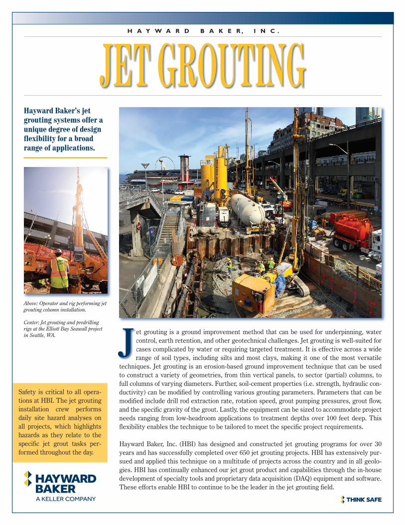
Above: Operator and rig performing jet grouting column installation.
Center: Jet grouting and predrilling rigs at the Elliott Bay Seawall project in Seattle, WA. et grouting is a ground improvement method that can be used for underpinning, water
control, earth retention, and other geotechnical challenges. Jet grouting is well-suited for cases complicated by water or requiring targeted treatment. It is effective across a wide range of soil types, including silts and most clays, making it one of the most versatile
techniques. Jet grouting is an erosion-based ground improvement technique that can be used to construct a variety of geometries, from thin vertical panels, to sector (partial) columns, to full columns of varying diameters. Further, soil-cement properties (i.e. strength, hydraulic con-ductivity) can be modified by controlling various grouting parameters. Parameters that can be modified include drill rod extraction rate, rotation speed, grout pumping pressures, grout flow, and the specific gravity of the grout. Lastly, the equipment can be sized to accommodate project needs ranging from low-headroom applications to treatment depths over 100 feet deep. This flexibility enables the technique to be tailored to meet the specific project requirements.
Hayward Baker, Inc. (HBI) has designed and constructed jet grouting programs for over 30 years and has successfully completed over 650 jet grouting projects. HBI has extensively pur-sued and applied this technique on a multitude of projects across the country and in all geolo-gies. HBI has continually enhanced our jet grout product and capabilities through the in-house development of specialty tools and proprietary data acquisition (DAQ) equipment and software. These efforts enable HBI to continue to be the leader in the jet grouting field.
range of soil types, including silts and most clays, making it one of the most versatile J
he jet grouting process has many unique aspects that enable it to perform in ways that other ground modification techniques cannot. Because jet grout is an erosional process which will create a relatively large column of soil-cement from a fairly small
borehole, it enables one to treat a soil strata at depth without disturbing the soils above it. Additionally, because the mixing occurs with a fluid and not with a mechanical tool, this allows for treating against an existing structure, such as a bulkhead, shaft wall, or concrete pipe. And lastly, the drill rigs used for jet grouting come in a range of different sizes; large ones capable of efficiently treat-ing to depths over 100 feet and very small ones capable of walking through a 30 inch door and working in a basement with only 6 feet 9 inches of headroom, making it a perfect technique for improving the foundation of an existing structure.
T
Technology & Applications . . .
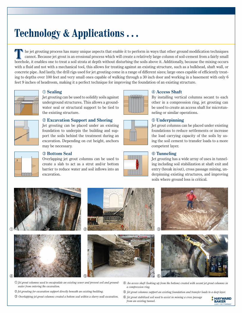
SealingJet grouting can be used to solidify soils against underground structures. This allows a ground-water seal or structural support to be tied to the existing structure.
Excavation Support and ShoringJet grouting can be placed under an existing foundation to underpin the building and sup-port the soils behind the treatment during an excavation. Depending on cut height, anchors may be necessary.
Bottom SealOverlapping jet grout columns can be used to create a slab to act as a strut and/or bottom barrier to reduce water and soil inflows into an excavation.
Access ShaftBy installing vertical columns secant to each other in a compression ring, jet grouting can be used to create an access shaft for microtun-neling or similar operations.
UnderpinningJet grout columns can be placed under existing foundations to reduce settlements or increase the load carrying capacity of the soils by us-ing the soil cement to transfer loads to a more competent layer.
TunnelingJet grouting has a wide array of uses in tunnel-ing including soil stabilization at shaft exit and entry (break in/out), cross passage mining, un-derpinning existing structures, and improving soils where ground loss is critical.
Jet grout columns used to encapsulate an existing sewer and prevent soil and ground-water from entering the excavation.
Jet grouting for excavation support directly beneath an existing building.
Overlapping jet grout columns created a bottom seal within a slurry wall excavation.
An access shaft (looking up from the bottom) created with secant jet grout columns in a compression ring.
Jet grout columns support an existing foundation and transfer loads to a deep layer.
Jet grout stabilized soil used to assist in mining a cross passage from an existing tunnel.

Jet Grouting ProceduresThe jet grouting process uses specialty drill tooling which in-cludes a grouting monitor attached to the end of a multi-cham-ber drill stem. Typically, the monitor is advanced to the targeted maximum treatment depth, at which time high velocity/energy grout jets (and sometimes water and air) are initiated through nozzles on the side of the monitor. The jets simultaneously erode and mix the in situ soil with binder as the drill stem and jet grout monitor are rotated and raised. The process contin-ues until the upper limits of the treatment zone are reached, at which time the tooling is withdrawn and the hole backfilled.
During the jetting process it is imperative that the desired jet-ting parameters are maintained. The onboard data acquisition system monitors the rotation rate and withdrawal rate, as well as the grout, air and water (if used) pressure, and grout flow. This information is displayed in real time for the operator, and data are wirelessly transmitted to the DAQ database where it is post-processed, stored and reviewed by the project team.
Depending on the geometry requirements, the monitor can be rotated continuously in the same direction to create a column or rotated partially back and forth to create any portion of a full 360 degree circular geometry. The monitor can also be held static as it is withdrawn to create panels in the targeted soil formation.
Critical to the success of jet grouting is ensuring spoils return to the surface. Borehole stability is paramount to spoils return and successful jet grouting. It is important for drill holes to be of ad-equate size to allow spoils to flow freely to the surface and pre-vent any potential flow restriction, reducing the risk of heave.
Jet Grouting Design ApplicationsThere a several design parameters that can be altered in the jet grout process. These include geometry, strength, and hydraulic conductivity (commonly referred to as permeability).
The shape of the jet grouted element can be modified as previ-ously described. Additionally, the size of the element can be var-ied, including both the diameter and length of the treated zone. The length of the treated zone is controlled by initial penetration of the monitor (bottom) and termination of the erosion or jetting process (top). The diameter is a function of the erosional energy of the jet and the erodibility of the soil. This change is made by varying the diameter of the fluid nozzles. The withdrawal rate can also be changed to increase or decrease the diameter of the jet grouted column. In general, the more granular and cohesion-less the soils are, the greater the erodibility. Gravels, however, can be difficult to assess. They can be either easily eroded or problematic to erode based on the geologic depositional process in which they were placed.
The strength and hydraulic conductivity of the soil-cement are both functions of the binder content and type of soil treated. The more granular or less cohesive the soils, typically the higher the strength. Higher binder contents can also yield lower hydraulic conductivities in certain soil types. The binder content can be modified by adjusting the specific gravity of the grout used in the jetting process. As well, Ground Granulated Blast Furnace Slag (GGBFS) as a binder and bentonite as an additive will typically provide lower hydraulic conductivities than Portland cement.
Procedures & Design Considerations . . .
Application limits forgrouting techniques
Grain size [mm Ø]
Clay Silt
Pass
ing
by w
eigh
t [%
]
Sand Gravel Cobbles
Mortar
Cement Suspension
Ultra Fine Cement
Silicate Gel [hv]
Sodium Silicate Solutions [lv]
Synthetic Solutions
Jet Grouting
economical
nv = low viscoushv = high viscous
0.002 0.006 0.02 0.06 0.2 0.6 2.0 6.0 20 60
100
80
60
40
20
0
Jet grouting has the broadest range of soil type applications of all the grouting technologies.
As our jet grouting experience and expertise has grown over the years, so has our need to stay on the leading edge of equip-ment advancement. This need has required that we look past commercially available jet grouting kits and produce our own data acquisition (DAQ) systems, rig control systems, and even our own fully-automated jet grouting rigs.
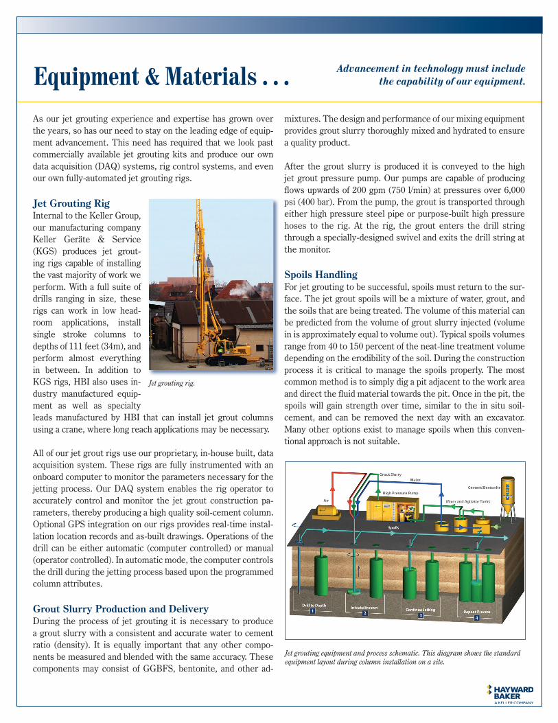
Jet Grouting Rig Internal to the Keller Group, our manufacturing company Keller Geräte & Service (KGS) produces jet grout-ing rigs capable of installing the vast majority of work we perform. With a full suite of drills ranging in size, these rigs can work in low head-room applications, install single stroke columns to depths of 111 feet (34m), and perform almost everything in between. In addition to KGS rigs, HBI also uses in-dustry manufactured equip-ment as well as specialty leads manufactured by HBI that can install jet grout columns using a crane, where long reach applications may be necessary.
All of our jet grout rigs use our proprietary, in-house built, data acquisition system. These rigs are fully instrumented with an onboard computer to monitor the parameters necessary for the jetting process. Our DAQ system enables the rig operator to accurately control and monitor the jet grout construction pa-rameters, thereby producing a high quality soil-cement column. Optional GPS integration on our rigs provides real-time instal-lation location records and as-built drawings. Operations of the drill can be either automatic (computer controlled) or manual (operator controlled). In automatic mode, the computer controls the drill during the jetting process based upon the programmed column attributes.
Grout Slurry Production and Delivery During the process of jet grouting it is necessary to produce a grout slurry with a consistent and accurate water to cement ratio (density). It is equally important that any other compo-nents be measured and blended with the same accuracy. These components may consist of GGBFS, bentonite, and other ad-
mixtures. The design and performance of our mixing equipment provides grout slurry thoroughly mixed and hydrated to ensure a quality product.
After the grout slurry is produced it is conveyed to the high jet grout pressure pump. Our pumps are capable of producing flows upwards of 200 gpm (750 l/min) at pressures over 6,000 psi (400 bar). From the pump, the grout is transported through either high pressure steel pipe or purpose-built high pressure hoses to the rig. At the rig, the grout enters the drill string through a specially-designed swivel and exits the drill string at the monitor.
Spoils Handling For jet grouting to be successful, spoils must return to the sur-face. The jet grout spoils will be a mixture of water, grout, and the soils that are being treated. The volume of this material can be predicted from the volume of grout slurry injected (volume in is approximately equal to volume out). Typical spoils volumes range from 40 to 150 percent of the neat-line treatment volume depending on the erodibility of the soil. During the construction process it is critical to manage the spoils properly. The most common method is to simply dig a pit adjacent to the work area and direct the fluid material towards the pit. Once in the pit, the spoils will gain strength over time, similar to the in situ soil-cement, and can be removed the next day with an excavator. Many other options exist to manage spoils when this conven-tional approach is not suitable.
Equipment & Materials . . . Advancement in technology must include the capability of our equipment.
Jet grouting rig.
Jet grouting equipment and process schematic. This diagram shows the standard equipment layout during column installation on a site.

QA/QC . . .
Quality Assurance is process oriented. It is a proactive quality process ensuring the right procedures are done correctly.
Quality Control is product oriented. It consists of activities, such as testing, which confirm quality of the product.
Quality Assurance To meet the intent of the project and ensure that the jet grout program is successful, an in situ test program is generally in-stalled prior to production. Based on review of the project bor-ings, the application, and previous project experience, initial jet grout parameters (or sets of parameters) are established and executed in the field for the test program. The test program will specifically demonstrate the column spacing, overlap, and ge-ometry of the jet grouted elements. The test program will also verify consistency of the grout batching, evaluate the equipment functionality, and confirm the real-time recording and reporting of the jet grout parameters. All of these processes are used to establish a standardized protocol for each specific soil type that is consistent and repeatable for the production columns.
HBI’s proprietary data acquisition (DAQ) system enables us to continuously monitor and record specific jet grout parameters at the rig. The DAQ interface provides real-time information to the drill rig operator, while the column construction data is uploaded wirelessly to a server soon after completion to be used for re-port generation. These reports can then be reviewed in near real-time by project management and submitted to the client.
Quality ControlWhile quality assurance helps standardize the process, quality control in jet grouting involves validating the work given the variable nature of soils across a site. Quality control is generally performed through periodic coring of the jet grout columns and sampling the wet spoils. Cores are visually inspected and logged for recovery and continuity. When insufficient core length is re-covered, down-hole cameras may be used to inspect the core hole in situ. Surface or in situ sampling of wet jet grout spoils is performed during the work to subsequently test the materials for performance requirements such as unconfined compressive strength and permeability. Fresh samples of the soil-cement are usually cast in concrete cylinders in the field and sent for labora-tory testing as required.
A coring sample to visually inspect the quality of jet grout installed during production. Operator using HBI’s proprietary DAQ.
HBI DAQ report for a jet grout column. The report is specifically designed for a quick, one page overview of the jet grout installation.
Column Number: 123 Date: 6/9/2015Job Number: 12345 Start Time: 9:54 AMJob Location: New York, NY End Time: 12:04 PMTotal Grout Volume: 46361 L Duration: 02:09:44Treatment Length: 12.99 m Avg. S.G.: 1.52
Jet Grouting Report
0.0
5.0
10.0
15.0
20.00
10
20
30
40
50
60
0.00 20.00 40.00 60.00 80.00 100.00 120.00 140.00
Dep
th (m
)
RPM
Time (min)
RPM Depth
0.0
5.0
10.0
15.0
20.00
20
40
60
80
100
0.00 20.00 40.00 60.00 80.00 100.00 120.00 140.00
Dep
th (m
)
Pull
Spee
d (c
m/m
in)
Time (min)
Pull Speed Depth
0.0
100.0
200.0
300.0
400.0
500.0
050
100150200250300350400
0.00 20.00 40.00 60.00 80.00 100.00 120.00 140.00
Gro
ut F
low
(lpm
)
Gro
ut P
ress
ure
(bar
)
Time (min)
Grout Pressure Grout Flow
0.0
2.0
4.0
6.0
8.0
10.0
02468
101214
0.00 20.00 40.00 60.00 80.00 100.00 120.00 140.00
Air
Flow
(m^3
/min
)
Air
Pres
sure
(bar
)
Time (min)
Air Pressure Air Flow
J E T G R O U T I N G
Advantages of Hayward Baker Jet Grouting
The North American leader in jet grouting for over 30 years.
Design, management, and field staff have experience in nearly all geologies and with all types of jet grouting applications.
Jet grouting can be combined with other techniques to provide a compre-hensive and cost-effective geotechnical solution.
Equipment and staff in over 30 regional offices across the country enables HBI to respond quickly and efficiently.
An extensive equipment fleet and a significant array of specialty tooling to address various geologic and logistical conditions.
In-house designed DAQ system docu-ments performance and provides quality assurance.
You have a strong partner with Hayward BakerHayward Baker, Inc. (HBI) is North America’s leader in geotechnical construction, offering the full range of construction services for foun-dation rehabilitation, settlement control, lique-faction mitigation, soil stabilization, groundwa-ter control, slope stability, excavation support, underpinning, and environmental remediation. HBI is annually ranked #1 in the profession by Engineering News-Record (ENR).
Headquartered in Hanover, Maryland, HBI has over 30 offices servicing North and Central America. Since its inception, HBI
has established itself in the forefront of geotechnical specialty contracting, evolving and expanding to meet the increasingly complex needs of the construction community. HBI offers design-build and bid-build services for the widest array of geotechnical construction applications.
HBI has the experience and innovation to as-sist engineers, contractors, and owners with identifying and constructing the most eco-nomical solution that satisfies the require-ments of each project, typical or unique.
Design-Build Services for the Complete Range of Geotechnical TechnologiesGroutingCement Grouting (High Mobility Grouting)Chemical GroutingCompaction Grouting (Low Mobility Grouting)Fracture GroutingJet GroutingPolyurethane GroutingGround ImprovementDry Soil MixingDynamic CompactionInjection Systems for Expansive SoilsRapid Impact CompactionRigid Inclusions (Controlled Sti� ness Columns)Vibro CompactionVibro Concrete ColumnsVibro Piers® (Aggregate Piers)Vibro Replacement (Stone Columns)Wet Soil MixingStructural SupportAugercast PilesDrilled ShaftsDriven PilesFranki Piles (PIFs)Helical PilesJacked PiersMacropiles®
MicropilesPit UnderpinningEarth RetentionAnchorsAnchor Block Slope StabilizationGabion SystemsMicropile Slide Stabilization System (MS³)Secant or Tangent PilesSheet PilesSoil NailingSoldier Piles & LaggingAdditional ServicesEarthquake Drains Sculpted ShotcreteSlab JackingSlurry WallsTRD Soil Mix WallsWick Drains
Website haywardbaker.comEmail [email protected]
Hayward Baker, Inc.A member of the Keller worldwide group of companies
Copyright 2017 Hayward Baker, Inc.H1-MAR-20001-JW Feb2017
For a complete list of our o� ces, visit: haywardbaker.com
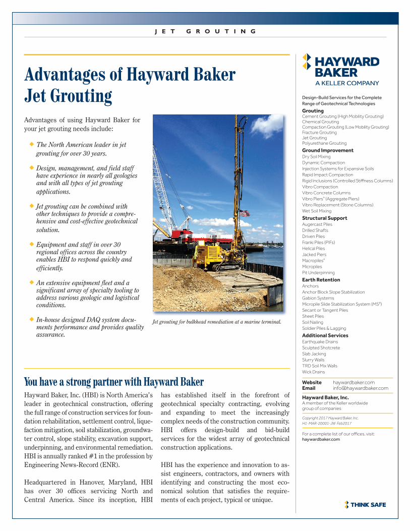
Jet grouting for bulkhead remediation at a marine terminal.
Advantages of using Hayward Baker for your jet grouting needs include: