jessada konpang a dual-mode wide-band bandpass filter using the
TRANSCRIPT

A Dual-Mode Wide-Band Bandpass Filter Using the Microstrip Loop Resonator with Tuning Stubs 341
A Dual-Mode Wide-Band Bandpass Filter Using the Microstrip Loop Resonator with Tuning Stubs
Jessada Konpang
x
A Dual-Mode Wide-Band Bandpass Filter Using the Microstrip Loop
Resonator with Tuning Stubs
Jessada Konpang Rajamangala University of Technology Krungthep
Thailand
1. Introduction
The broadband wireless access (BWA) is an important issue in current developments of the modern wireless communication system. To meet this trend, the bandpass filters with relatively wide bandwidth are frequently required in the RF front ends. In microwave communication systems, the bandpass filter is an essential component, which is usually used in both receivers and transmitters. Thus, the quality of bandpass filers is extremely important. Planar filters are currently a popular structure because they can be fabricated using printed circuit technology and are suitable for commercial applications due to their small size and lower fabrication cost (D.M. Pozar, 1998). Therefore, how to design a bandpass filter at low cost and with high performance is currently of great interest. Microstrip bandpass filters can be easily mounted on a dielectric substrate and can provide a more flexible design of the circuit layout. The dual-mode resonators filter have been known for years. The compact high performance microwave bandpass filters are highly desirable in the wireless communications systems. Consequently, the dual-mode filters have been used widely for the system because of their advantages such as small size, light weight, low loss and high selectivity. Many authors (Hsieh & Chang, 2001, 2003), (Konpang, 2003) and (Chen et al., 2005) have proposed the wide-band bandpass filters using dual-mode ring resonators with tuning stubs but the configurations still occupy a large circuit area, which is not suitable for wireless communication systems where the miniaturization is an important factor. Therefore, it is desirable to develop new types of dual-mode microstrip resonators not only for offering alternative designs, but also for miniaturizing filters. On the other hand, the modern wireless communication systems require the bandpass filters having effective out-of-band spurious rejection and good in-band performance. The resonators with reasonable spurious are required to meet the out-of-band requirements. The microstrip open-loop resonators have a wide stopband resulting from the dispersion effect and the slow-wave effect (Hong & Lancaster, 1997) and (Görür, 2002). In this book, a dual-mode wide-band bandpass filter using the microstrip loop resonators with tuning stubs is proposed. Basic concepts and design equations for microstrip lines introduced in section 2. The bandpass filter is based on the bandstop filter employing direct-
16
www.intechopen.com

Passive Microwave Components and Antennas342
connected feed lines on the orthogonal of the microstrip loop resonators. The introduction of two tuning open stubs connecting opposite to the ports widens the passband and sharpens the stopbands. Then, a dual-mode can be used to improve the narrow stopbands for lower side band and higher sideband. The design descriptions dual-mode wide-band bandpass filter are discussed in section 3.
2. Transmission lines
Basic concepts and design equations for microstrip lines, dual-mode wide-band bandpass filter using the microstrip loop resonator with tuning stubs are briefly described.
2.1 Microstrip lines 2.1.1 Microstrip structure The general structure of a microstrip is illustrated in Figure 1. A conducting strip (microstrip line) with a width w and a thickness t is on the top of a dielectric substrate that has a relative dielectric constant r and a thickness h , and the bottom of the substrate is a ground (conducting) plane.
h
t
rGround plane
Conducting strip
w
Fig. 1. General microstrip structure 2.1.2 Waves in microstrips The fields in the microstrip extend within two media-air above and dielectric below so that the structure is inhomogeneous. Due to this inhomogeneous nature, the microstrip does not support a pure TEM wave. This is because that a pure TEM wave has only transverse components, and its propagation velocity depends only on the material properties, namely the permittivity ε and the permeability . However, with the presence of the two guided-wave media (the dielectric substrate and the air), the waves in a microstrip line will have no vanished longitudinal components of electric and magnetic fields, and their propagation velocities will depend not only on the material properties, but also on the physical dimensions of the microstrip.
2.1.3 Quasi-TEM approximation When the longitudinal components of the fields for the dominant mode of a microstrip line remain very much smaller than the transverse components, they may be neglected. In this
case, the dominant mode then behaves like a TEM mode, and the TEM transmission line theory is applicable for the microstrip line as well. This is called the quasi-TEM approximation and it is valid over most of the operating frequency ranges of microstrip.
2.1.4 Effective dielectric constant and characteristic impedance In the quasi-TEM approximation, a homogeneous dielectric material with an effective dielectric permittivity replaces the inhomogeneous dielectric-air media of microstrip. Transmission characteristics of microstrips are described by two parameters, namely the effective dielectric constant re and characteristic impedance cZ , which may then be obtained by quasistatic analysis. In quasi-static analysis, the fundamental mode of wave propagation in a microstrip is assumed to be pure TEM. The above two parameters of microstrips are then determined from the values of two capacitances as follows
dre
a
CC
(1)
1c
a d
Zc C C
in which dC is the capacitance per unit length with the dielectric substrate present, aC is the capacitance per unit length with the dielectric substrate replaced by air, and c is the velocity of electromagnetic waves in free space 8( 3.0 10 / ).c m s For very thin conductors (i.e., t → 0), the closed-form expressions that provide an accuracy better than one percent are given as follows (Hong & Lancaster, 2001). For / 1w h :
0.5 21 1 1 12 0.04 1
2 2r r
reh ww h
(2a)
8ln 0.252c
re
h wZw h
(2b)
where 120 ohms is the wave impedance in free space. For / 1w h :
0.51 1 1 12
2 2r r
rehw
(3a)
1
1.393 0.677 ln 1.444cre
w wZh h
(3b)
Accurate expression for the effective dielectric constant is
www.intechopen.com

A Dual-Mode Wide-Band Bandpass Filter Using the Microstrip Loop Resonator with Tuning Stubs 343
connected feed lines on the orthogonal of the microstrip loop resonators. The introduction of two tuning open stubs connecting opposite to the ports widens the passband and sharpens the stopbands. Then, a dual-mode can be used to improve the narrow stopbands for lower side band and higher sideband. The design descriptions dual-mode wide-band bandpass filter are discussed in section 3.
2. Transmission lines
Basic concepts and design equations for microstrip lines, dual-mode wide-band bandpass filter using the microstrip loop resonator with tuning stubs are briefly described.
2.1 Microstrip lines 2.1.1 Microstrip structure The general structure of a microstrip is illustrated in Figure 1. A conducting strip (microstrip line) with a width w and a thickness t is on the top of a dielectric substrate that has a relative dielectric constant r and a thickness h , and the bottom of the substrate is a ground (conducting) plane.
h
t
rGround plane
Conducting strip
w
Fig. 1. General microstrip structure 2.1.2 Waves in microstrips The fields in the microstrip extend within two media-air above and dielectric below so that the structure is inhomogeneous. Due to this inhomogeneous nature, the microstrip does not support a pure TEM wave. This is because that a pure TEM wave has only transverse components, and its propagation velocity depends only on the material properties, namely the permittivity ε and the permeability . However, with the presence of the two guided-wave media (the dielectric substrate and the air), the waves in a microstrip line will have no vanished longitudinal components of electric and magnetic fields, and their propagation velocities will depend not only on the material properties, but also on the physical dimensions of the microstrip.
2.1.3 Quasi-TEM approximation When the longitudinal components of the fields for the dominant mode of a microstrip line remain very much smaller than the transverse components, they may be neglected. In this
case, the dominant mode then behaves like a TEM mode, and the TEM transmission line theory is applicable for the microstrip line as well. This is called the quasi-TEM approximation and it is valid over most of the operating frequency ranges of microstrip.
2.1.4 Effective dielectric constant and characteristic impedance In the quasi-TEM approximation, a homogeneous dielectric material with an effective dielectric permittivity replaces the inhomogeneous dielectric-air media of microstrip. Transmission characteristics of microstrips are described by two parameters, namely the effective dielectric constant re and characteristic impedance cZ , which may then be obtained by quasistatic analysis. In quasi-static analysis, the fundamental mode of wave propagation in a microstrip is assumed to be pure TEM. The above two parameters of microstrips are then determined from the values of two capacitances as follows
dre
a
CC
(1)
1c
a d
Zc C C
in which dC is the capacitance per unit length with the dielectric substrate present, aC is the capacitance per unit length with the dielectric substrate replaced by air, and c is the velocity of electromagnetic waves in free space 8( 3.0 10 / ).c m s For very thin conductors (i.e., t → 0), the closed-form expressions that provide an accuracy better than one percent are given as follows (Hong & Lancaster, 2001). For / 1w h :
0.5 21 1 1 12 0.04 1
2 2r r
reh ww h
(2a)
8ln 0.252c
re
h wZw h
(2b)
where 120 ohms is the wave impedance in free space. For / 1w h :
0.51 1 1 12
2 2r r
rehw
(3a)
1
1.393 0.677 ln 1.444cre
w wZh h
(3b)
Accurate expression for the effective dielectric constant is
www.intechopen.com
Passive Microwave Components and Antennas344
1 1 101
2 2
abr r
re u (4)
Where /u w h , and
24
3
4
1 1521 ln ln 149 0.432 18.7 18.1
uu uau
0.053
0.90.5643
r
r
b
The accuracy of this model is better than 0.2% for r ≤ 128 and 0.01 ≤ u ≤ 100. The more accurate expression for the characteristic impedance is
22ln 1
2cre
FZu u
(5)
where u = w/h, η = 120π ohms, and
0.752830.6666 (2 6)expF
u
The accuracy for c reZ is better than 0.01% for u ≤ 1 and 0.03% for u ≤ 1000.
2.1.5 Guided wavelength, propagation constant, phase velocity, and electrical length Once the effective dielectric constant of a microstrip is determined, the guided wavelength of the quasi-TEM mode of microstrip is given by 0
gre
(6a)
where 0 is the free space wavelength at operation frequency f. More conveniently, where the frequency is given in gigahertz (GHz), the guided wavelength can be evaluated directly in millimeters as follows:
300( )g
re
mmf GHz
(6b)
The associated propagation constant (β) and phase velocity (vp) can be determined by 2
g
(7)
pre
w cv (8)
where c is the velocity of light 8( 3.0 10 / )c m s in free space. The electrical length (θ) for a given physical length (l) of the microstrip is defined by l (9)
Therefore, θ = π/2 when l = λg/4, and θ = π when l = λg/2. These so-called quarterwavelength and half-wavelength microstrip lines are important for design of microstrip filters.
2.1.6 Synthesis of w/h Approximate expressions for w/h in terms of Zc and r are available. For w/h ≤ 2
8exp( )
exp(2 ) 2w Ah A
(10)
with
0.51 1 0.110.23
60 2 1c r r
r r
ZA (11)
and for w/h ≥ 2
2 1 0.61( 1) ln(2 1) ln( 1) 0.392r
r r
w B B Bh
(11)
with 260
c r
BZ
These expressions also provide accuracy better than one percent. If more accurate values are needed, an iterative or optimization process based on the more accurate analysis models described previously can be employed.
2.1.7 Effect of strip thickness So far we have not considered the effect of conducting strip thickness t (as referring to Figure 1). The thickness t is usually very small when the microstrip line is realized by conducting thin films; therefore, its effect may quite often be neglected. Nevertheless, its effect on the characteristic impedance and effective dielectric constant may be included. For w/h ≤ 1:
8 ( )( ) ln 0.25( )/2
ec
ere
w tZ tw t h h
(12a)
For w/h ≥ 1:
www.intechopen.com
A Dual-Mode Wide-Band Bandpass Filter Using the Microstrip Loop Resonator with Tuning Stubs 345
1 1 101
2 2
abr r
re u (4)
Where /u w h , and
24
3
4
1 1521 ln ln 149 0.432 18.7 18.1
uu uau
0.053
0.90.5643
r
r
b
The accuracy of this model is better than 0.2% for r ≤ 128 and 0.01 ≤ u ≤ 100. The more accurate expression for the characteristic impedance is
22ln 1
2cre
FZu u
(5)
where u = w/h, η = 120π ohms, and
0.752830.6666 (2 6)expF
u
The accuracy for c reZ is better than 0.01% for u ≤ 1 and 0.03% for u ≤ 1000.
2.1.5 Guided wavelength, propagation constant, phase velocity, and electrical length Once the effective dielectric constant of a microstrip is determined, the guided wavelength of the quasi-TEM mode of microstrip is given by 0
gre
(6a)
where 0 is the free space wavelength at operation frequency f. More conveniently, where the frequency is given in gigahertz (GHz), the guided wavelength can be evaluated directly in millimeters as follows:
300( )g
re
mmf GHz
(6b)
The associated propagation constant (β) and phase velocity (vp) can be determined by 2
g
(7)
pre
w cv (8)
where c is the velocity of light 8( 3.0 10 / )c m s in free space. The electrical length (θ) for a given physical length (l) of the microstrip is defined by l (9)
Therefore, θ = π/2 when l = λg/4, and θ = π when l = λg/2. These so-called quarterwavelength and half-wavelength microstrip lines are important for design of microstrip filters.
2.1.6 Synthesis of w/h Approximate expressions for w/h in terms of Zc and r are available. For w/h ≤ 2
8exp( )
exp(2 ) 2w Ah A
(10)
with
0.51 1 0.110.23
60 2 1c r r
r r
ZA (11)
and for w/h ≥ 2
2 1 0.61( 1) ln(2 1) ln( 1) 0.392r
r r
w B B Bh
(11)
with 260
c r
BZ
These expressions also provide accuracy better than one percent. If more accurate values are needed, an iterative or optimization process based on the more accurate analysis models described previously can be employed.
2.1.7 Effect of strip thickness So far we have not considered the effect of conducting strip thickness t (as referring to Figure 1). The thickness t is usually very small when the microstrip line is realized by conducting thin films; therefore, its effect may quite often be neglected. Nevertheless, its effect on the characteristic impedance and effective dielectric constant may be included. For w/h ≤ 1:
8 ( )( ) ln 0.25( )/2
ec
ere
w tZ tw t h h
(12a)
For w/h ≥ 1:
www.intechopen.com

Passive Microwave Components and Antennas346
1( ) ( )( ) 1.393 0.667 ln 1.444e ec
re
w t w tZ th h
(12b)
where
1.25 41 ln / 0.5( )
1.25 21 ln / 0.5
e
w t w w hh h tw t
h w t h w hh h t
(13a)
1 /( )
4.6 /r
re ret htw h
(13b)
In the above expressions, re is the effective dielectric constant for t = 0. It can be observed that the effect of strip thickness on both the characteristic impedance and effective dielectric constant is insignificant for small values of t/h. However, the effect of strip thickness is significant for conductor loss of the microstrip line.
2.1.8 Dispersion in microstrip Generally speaking, there is dispersion in microstrips; namely, its phase velocity is not a constant but depends on frequency. It follows that its effective dielectric constant re is a function of frequency and can in general be defined as the frequencydependent effective dielectric constant ( )re f . The previous expressions for re are obtained based on the quasi-TEM or quasistatic approximation, and therefore are rigorous only with DC. At low microwave frequencies, these expressions provide a good approximation. To take into account the effect of dispersion, the formula of ( )re f is given as follows (Hong & Lancaster, 2001).
50
( )1 /
r rere r mf
f f (14)
where
050 1.730.75 0.75 0.332 /
TM
r
ff
w h (15a)
0
1 1tan
2re
TM rr rer re
cfh
(15b)
0 2.32cm m m (16a)
3
01 11 0.32
1 / 1 /m
w h w h (16b)
50
0.451.41 0.15 0.235exp for / 0.71 /
1 for / 0.7c
f w hm w h f
w h
(16c)
where c is the velocity of light in free space, and whenever the product m0mc is greater than 2.32, the parameter m is chosen equal to 2.32. The dispersion model shows that the ( )re f increases with frequency, and ( )re f → r as f → ∞. The accuracy is estimated to be within 0.6% for 0.1 ≤ w/h ≤10, 1 ≤ r ≤ 128 and for any value of h/λ0. The effect of dispersion on the characteristic impedance may be estimated by
( ) 1( )1 ( )
re rec c
re re
fZ f Zf
(17)
where Zc is the quasi-static value of characteristic impedance obtained earlier.
2.2 Microstrip discontinuities Microstrip discontinuities commonly encountered in the layout of practical filters include junctions, bends and open stubs. Generally speaking, the effects of discontinuities can be more accurately modeled and taken into account in the filter designs with full-wave electromagnetic (EM) simulations.
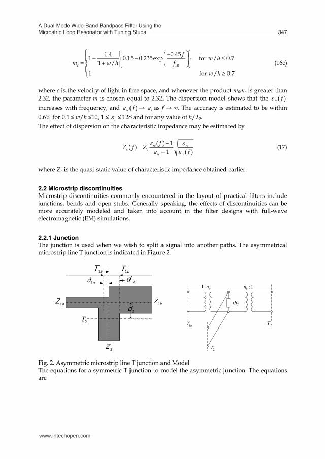
2.2.1 Junction The junction is used when we wish to split a signal into another paths. The asymmetrical microstrip line T junction is indicated in Figure 2.
1bZaZ 1
ad1 bd 1
bT1aT1
2Z
2T2d
1: an
TjB
1bT
2T
1aT
:1bn
Fig. 2. Asymmetric microstrip line T junction and Model The equations for a symmetric T junction to model the asymmetric junction. The equations are
www.intechopen.com
A Dual-Mode Wide-Band Bandpass Filter Using the Microstrip Loop Resonator with Tuning Stubs 347
1( ) ( )( ) 1.393 0.667 ln 1.444e ec
re
w t w tZ th h
(12b)
where
1.25 41 ln / 0.5( )
1.25 21 ln / 0.5
e
w t w w hh h tw t
h w t h w hh h t
(13a)
1 /( )
4.6 /r
re ret htw h
(13b)
In the above expressions, re is the effective dielectric constant for t = 0. It can be observed that the effect of strip thickness on both the characteristic impedance and effective dielectric constant is insignificant for small values of t/h. However, the effect of strip thickness is significant for conductor loss of the microstrip line.
2.1.8 Dispersion in microstrip Generally speaking, there is dispersion in microstrips; namely, its phase velocity is not a constant but depends on frequency. It follows that its effective dielectric constant re is a function of frequency and can in general be defined as the frequencydependent effective dielectric constant ( )re f . The previous expressions for re are obtained based on the quasi-TEM or quasistatic approximation, and therefore are rigorous only with DC. At low microwave frequencies, these expressions provide a good approximation. To take into account the effect of dispersion, the formula of ( )re f is given as follows (Hong & Lancaster, 2001).
50
( )1 /
r rere r mf
f f (14)
where
050 1.730.75 0.75 0.332 /
TM
r
ff
w h (15a)
0
1 1tan
2re
TM rr rer re
cfh
(15b)
0 2.32cm m m (16a)
3
01 11 0.32
1 / 1 /m
w h w h (16b)
50
0.451.41 0.15 0.235exp for / 0.71 /
1 for / 0.7c
f w hm w h f
w h
(16c)
where c is the velocity of light in free space, and whenever the product m0mc is greater than 2.32, the parameter m is chosen equal to 2.32. The dispersion model shows that the ( )re f increases with frequency, and ( )re f → r as f → ∞. The accuracy is estimated to be within 0.6% for 0.1 ≤ w/h ≤10, 1 ≤ r ≤ 128 and for any value of h/λ0. The effect of dispersion on the characteristic impedance may be estimated by
( ) 1( )1 ( )
re rec c
re re
fZ f Zf
(17)
where Zc is the quasi-static value of characteristic impedance obtained earlier.
2.2 Microstrip discontinuities Microstrip discontinuities commonly encountered in the layout of practical filters include junctions, bends and open stubs. Generally speaking, the effects of discontinuities can be more accurately modeled and taken into account in the filter designs with full-wave electromagnetic (EM) simulations.
2.2.1 Junction The junction is used when we wish to split a signal into another paths. The asymmetrical microstrip line T junction is indicated in Figure 2.
1bZaZ 1
ad1 bd 1
bT1aT1
2Z
2T2d
1: an
TjB
1bT
2T
1aT
:1bn
Fig. 2. Asymmetric microstrip line T junction and Model The equations for a symmetric T junction to model the asymmetric junction. The equations are
www.intechopen.com
Passive Microwave Components and Antennas348
2
1 1 1
2 2 1 2
0.055 1 2a a a
p
fd Z ZD Z f Z
(18)
2
1 1 1
2 2 1 2
0.055 1 2b b b
p
fd Z ZD Z f Z
(19)
1 12
1 2
2
1 1 1 1 1 1
2 1 2 2
0.5 0.05 0.7 exp 1.6
0.25 0.17 ln
a b
a b a b a b
p
Z ZdD Z
Z Z Z Z Z ZfZ f Z Z
(20)
2 22
2 1 2
1 2 1
11 0.512
aa
p
f Z dnf Z D
(21)
2 22
2 1 2
1 2 1
11 0.512
bb
p
f Z dnf Z D
(22)
2
1 1 1 11
2 1 2 2 1
21 1 22 1
2 0 2
25.5 1 0.9ln 4.5
4.4exp 1.3 20
a b a bT r
r p
a b
Z Z Z Z fBY D Z Z f
Z Z Z dnZ D
(23)
where
0
re c
hDZ
(24)
0.4( ) c
pZf GHz
h (25)
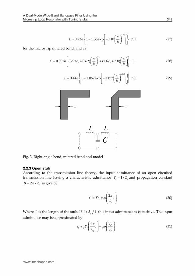
2.2.2 Bends Right-angle bend and mitered bend of microstrips may be modeled by and equivalent T-network, as shown in Figure 3. (Kupta et al., 1996) have given closed-form expressions for evaluation of capacitance and inductance:
2
0.001 (10.35 2.5) (2.6 5.64) Fr rw wC h ph h
(26)
1.39
0.22 1 1.35exp 0.18 nHwL hh
(27)
for the microstrip mitered bend, and as
2
0.001 (3.93 0.62) (7.6 3.8) Fr rw wC h ph h
(28)
0.947
0.44 1 1.062exp 0.177 nHwL hh
(29)
w w
CL L
Fig. 3. Right-angle bend, mitered bend and model 2.2.3 Open stub According to the transmission line theory, the input admittance of an open circuited transmission line having a characteristic admittance 1/c cY Z and propagation constant
2 / g is give by
2tant cg
Y jY l
(30)
Where l is the length of the stub. If /4gl this input admittance is capacitive. The input admittance may be approximated by
2 ct c
g p
Y lY jY l jv
(31)
www.intechopen.com
A Dual-Mode Wide-Band Bandpass Filter Using the Microstrip Loop Resonator with Tuning Stubs 349
2
1 1 1
2 2 1 2
0.055 1 2a a a
p
fd Z ZD Z f Z
(18)
2
1 1 1
2 2 1 2
0.055 1 2b b b
p
fd Z ZD Z f Z
(19)
1 12
1 2
2
1 1 1 1 1 1
2 1 2 2
0.5 0.05 0.7 exp 1.6
0.25 0.17 ln
a b
a b a b a b
p
Z ZdD Z
Z Z Z Z Z ZfZ f Z Z
(20)
2 22
2 1 2
1 2 1
11 0.512
aa
p
f Z dnf Z D
(21)
2 22
2 1 2
1 2 1
11 0.512
bb
p
f Z dnf Z D
(22)
2
1 1 1 11
2 1 2 2 1
21 1 22 1
2 0 2
25.5 1 0.9ln 4.5
4.4exp 1.3 20
a b a bT r
r p
a b
Z Z Z Z fBY D Z Z f
Z Z Z dnZ D
(23)
where
0
re c
hDZ
(24)
0.4( ) c
pZf GHz
h (25)
2.2.2 Bends Right-angle bend and mitered bend of microstrips may be modeled by and equivalent T-network, as shown in Figure 3. (Kupta et al., 1996) have given closed-form expressions for evaluation of capacitance and inductance:
2
0.001 (10.35 2.5) (2.6 5.64) Fr rw wC h ph h
(26)
1.39
0.22 1 1.35exp 0.18 nHwL hh
(27)
for the microstrip mitered bend, and as
2
0.001 (3.93 0.62) (7.6 3.8) Fr rw wC h ph h
(28)
0.947
0.44 1 1.062exp 0.177 nHwL hh
(29)
w w
CL L
Fig. 3. Right-angle bend, mitered bend and model 2.2.3 Open stub According to the transmission line theory, the input admittance of an open circuited transmission line having a characteristic admittance 1/c cY Z and propagation constant
2 / g is give by
2tant cg
Y jY l
(30)
Where l is the length of the stub. If /4gl this input admittance is capacitive. The input admittance may be approximated by
2 ct c
g p
Y lY jY l jv
(31)
www.intechopen.com
Passive Microwave Components and Antennas350
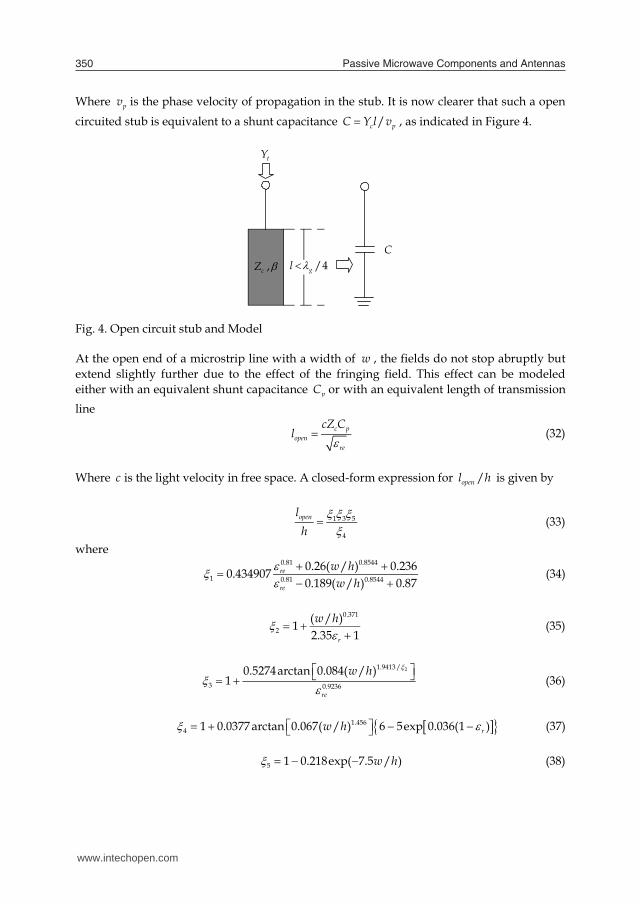
Where pv is the phase velocity of propagation in the stub. It is now clearer that such a open circuited stub is equivalent to a shunt capacitance /c pC Y l v , as indicated in Figure 4.
/4gl ,cZ
tY
C
Fig. 4. Open circuit stub and Model At the open end of a microstrip line with a width of w , the fields do not stop abruptly but extend slightly further due to the effect of the fringing field. This effect can be modeled either with an equivalent shunt capacitance pC or with an equivalent length of transmission line
c popen
re
cZ Cl (32)
Where c is the light velocity in free space. A closed-form expression for /openl h is given by
1 3 5
4
openlh
(33)
where 0.81 0.8544
1 0.81 0.8544
0.26( / ) 0.2360.4349070.189( / ) 0.87
re
re
w hw h
(34)
0.371
2( / )12.35 1r
w h (35)
21.9413 /
3 0.9236
0.5274arctan 0.084( / )1
re
w h (36)
1.4564 1 0.0377 arctan 0.067( / ) 6 5exp 0.036(1 )rw h (37)
5 1 0.218exp( 7.5 / )w h (38)
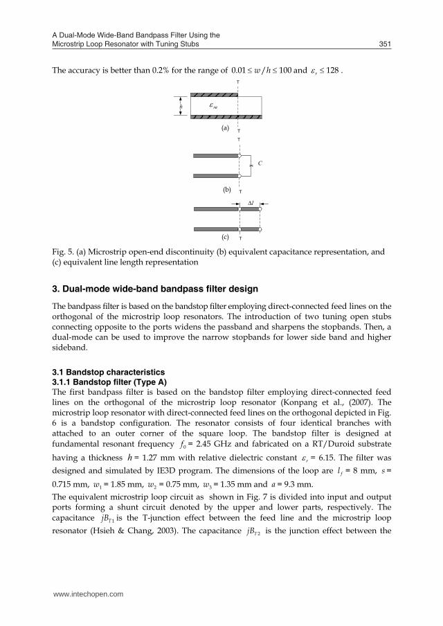
The accuracy is better than 0.2% for the range of 0.01 / 100w h and 128r .
reT
T
C
T
T
l
T
(a)
h
(b)
(c)
Fig. 5. (a) Microstrip open-end discontinuity (b) equivalent capacitance representation, and (c) equivalent line length representation 3. Dual-mode wide-band bandpass filter design
The bandpass filter is based on the bandstop filter employing direct-connected feed lines on the orthogonal of the microstrip loop resonators. The introduction of two tuning open stubs connecting opposite to the ports widens the passband and sharpens the stopbands. Then, a dual-mode can be used to improve the narrow stopbands for lower side band and higher sideband.
3.1 Bandstop characteristics 3.1.1 Bandstop filter (Type A) The first bandpass filter is based on the bandstop filter employing direct-connected feed lines on the orthogonal of the microstrip loop resonator (Konpang et al., (2007). The microstrip loop resonator with direct-connected feed lines on the orthogonal depicted in Fig. 6 is a bandstop configuration. The resonator consists of four identical branches with attached to an outer corner of the square loop. The bandstop filter is designed at fundamental resonant frequency 0f = 2.45 GHz and fabricated on a RT/Duroid substrate having a thickness h = 1.27 mm with relative dielectric constant r = 6.15. The filter was designed and simulated by IE3D program. The dimensions of the loop are fl = 8 mm, s = 0.715 mm, 1w = 1.85 mm, 2w = 0.75 mm, 3w = 1.35 mm and a = 9.3 mm. The equivalent microstrip loop circuit as shown in Fig. 7 is divided into input and output ports forming a shunt circuit denoted by the upper and lower parts, respectively. The capacitance 1TjB is the T-junction effect between the feed line and the microstrip loop resonator (Hsieh & Chang, 2003). The capacitance 2TjB is the junction effect between the
www.intechopen.com
A Dual-Mode Wide-Band Bandpass Filter Using the Microstrip Loop Resonator with Tuning Stubs 351
Where pv is the phase velocity of propagation in the stub. It is now clearer that such a open circuited stub is equivalent to a shunt capacitance /c pC Y l v , as indicated in Figure 4.
/4gl ,cZ
tY
C
Fig. 4. Open circuit stub and Model At the open end of a microstrip line with a width of w , the fields do not stop abruptly but extend slightly further due to the effect of the fringing field. This effect can be modeled either with an equivalent shunt capacitance pC or with an equivalent length of transmission line
c popen
re
cZ Cl (32)
Where c is the light velocity in free space. A closed-form expression for /openl h is given by
1 3 5
4
openlh
(33)
where 0.81 0.8544
1 0.81 0.8544
0.26( / ) 0.2360.4349070.189( / ) 0.87
re
re
w hw h
(34)
0.371
2( / )12.35 1r
w h (35)
21.9413 /
3 0.9236
0.5274arctan 0.084( / )1
re
w h (36)
1.4564 1 0.0377 arctan 0.067( / ) 6 5exp 0.036(1 )rw h (37)
5 1 0.218exp( 7.5 / )w h (38)
The accuracy is better than 0.2% for the range of 0.01 / 100w h and 128r .
reT
T
C
T
T
l
T
(a)
h
(b)
(c)
Fig. 5. (a) Microstrip open-end discontinuity (b) equivalent capacitance representation, and (c) equivalent line length representation 3. Dual-mode wide-band bandpass filter design
The bandpass filter is based on the bandstop filter employing direct-connected feed lines on the orthogonal of the microstrip loop resonators. The introduction of two tuning open stubs connecting opposite to the ports widens the passband and sharpens the stopbands. Then, a dual-mode can be used to improve the narrow stopbands for lower side band and higher sideband.
3.1 Bandstop characteristics 3.1.1 Bandstop filter (Type A) The first bandpass filter is based on the bandstop filter employing direct-connected feed lines on the orthogonal of the microstrip loop resonator (Konpang et al., (2007). The microstrip loop resonator with direct-connected feed lines on the orthogonal depicted in Fig. 6 is a bandstop configuration. The resonator consists of four identical branches with attached to an outer corner of the square loop. The bandstop filter is designed at fundamental resonant frequency 0f = 2.45 GHz and fabricated on a RT/Duroid substrate having a thickness h = 1.27 mm with relative dielectric constant r = 6.15. The filter was designed and simulated by IE3D program. The dimensions of the loop are fl = 8 mm, s = 0.715 mm, 1w = 1.85 mm, 2w = 0.75 mm, 3w = 1.35 mm and a = 9.3 mm. The equivalent microstrip loop circuit as shown in Fig. 7 is divided into input and output ports forming a shunt circuit denoted by the upper and lower parts, respectively. The capacitance 1TjB is the T-junction effect between the feed line and the microstrip loop resonator (Hsieh & Chang, 2003). The capacitance 2TjB is the junction effect between the
www.intechopen.com

Passive Microwave Components and Antennas352
loop resonator with each branch. The analysis of the characteristic of the microstrip loop resonators is performed by IE3D program. Fig.8 presents the simulation results of the microstrip loop using direct-connect orthogonal feed lines, the frequency response exhibits bandstop behaviours.
Port1fl
1w
Port 2
a3w
2ws
Fig. 6. Microstrip loop resonator using direct-connected orthogonal feeders (Type A)
fl
fl
l
l
Port 2
Port 11TjB
l
ll l l l ll
l
lll2TJB 2TJB
2TJB2TJB2TJB
Fig. 7. Equivalent circuit of the microstrip loop resonator using direct-connected orthogonal feed lines
Fig. 8. Simulation results of the microstrip loop resonator using direct-connected orthogonal feed lines
3.1.2 Bandstop filter (Type B) The second bandpass filter is based on the bandstop filter employing direct-connected feed lines on the orthogonal of the microstrip loop resonator (J. Konpang, 2008). The microstrip loop resonator with direct-connected feed lines on the orthogonal depicted in Fig.9 is a bandstop configuration. The resonator consists of four identical branches with a small square patch attached to an inner corner of the square loop.
Port 1
Port 2
fl
2w
g 5w1w
b
4w
Fig. 9. Microstrip loop resonator using direct-connected orthogonal feeders (Type B)
www.intechopen.com

A Dual-Mode Wide-Band Bandpass Filter Using the Microstrip Loop Resonator with Tuning Stubs 353
loop resonator with each branch. The analysis of the characteristic of the microstrip loop resonators is performed by IE3D program. Fig.8 presents the simulation results of the microstrip loop using direct-connect orthogonal feed lines, the frequency response exhibits bandstop behaviours.
Port1fl
1w
Port 2
a3w
2ws
Fig. 6. Microstrip loop resonator using direct-connected orthogonal feeders (Type A)
fl
fl
l
l
Port 2
Port 11TjB
l
ll l l l ll
l
lll2TJB 2TJB
2TJB2TJB2TJB
Fig. 7. Equivalent circuit of the microstrip loop resonator using direct-connected orthogonal feed lines
Fig. 8. Simulation results of the microstrip loop resonator using direct-connected orthogonal feed lines
3.1.2 Bandstop filter (Type B) The second bandpass filter is based on the bandstop filter employing direct-connected feed lines on the orthogonal of the microstrip loop resonator (J. Konpang, 2008). The microstrip loop resonator with direct-connected feed lines on the orthogonal depicted in Fig.9 is a bandstop configuration. The resonator consists of four identical branches with a small square patch attached to an inner corner of the square loop.
Port 1
Port 2
fl
2w
g 5w1w
b
4w
Fig. 9. Microstrip loop resonator using direct-connected orthogonal feeders (Type B)
www.intechopen.com
Passive Microwave Components and Antennas354
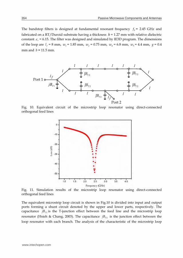
The bandstop filters is designed at fundamental resonant frequency 0f = 2.45 GHz and fabricated on a RT/Duroid substrate having a thickness h = 1.27 mm with relative dielectric constant r = 6.15. The filter was designed and simulated by IE3D program. The dimensions of the loop are fl = 8 mm, 1w = 1.85 mm, 2w = 0.75 mm, 4w = 6.8 mm, 5w = 4.4 mm, g = 0.4 mm and b = 11.5 mm.
fl
fl
l
l
Port 2
Port 11TjB
l
ll l l
l
l
lll
2TJB
2TJB
2TJB
2TJB 2TJB
l l
Fig. 10. Equivalent circuit of the microstrip loop resonator using direct-connected orthogonal feed lines
Fig. 11. Simulation results of the microstrip loop resonator using direct-connected orthogonal feed lines The equivalent microstrip loop circuit is shown in Fig.10 is divided into input and output ports forming a shunt circuit denoted by the upper and lower parts, respectively. The capacitance 1TjB is the T-junction effect between the feed line and the microstrip loop resonator (Hsieh & Chang, 2003). The capacitance 2TjB is the junction effect between the loop resonator with each branch. The analysis of the characteristic of the microstrip loop
resonators is performed by IE3D program. Fig.11 presents the simulation results of the microstrip loop using direct-connect orthogonal feed lines. The frequency response exhibits bandstop behaviours.
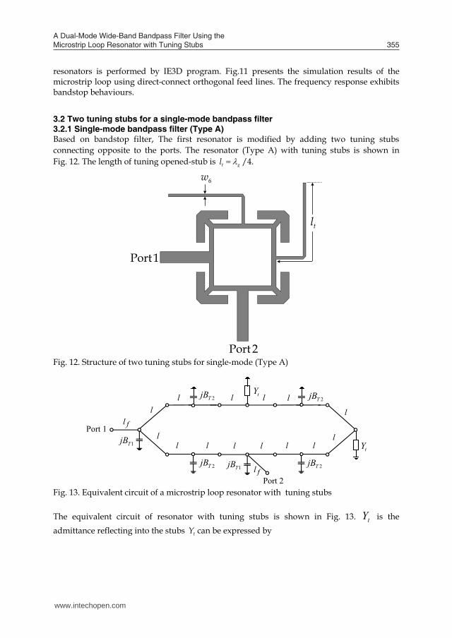
3.2 Two tuning stubs for a single-mode bandpass filter 3.2.1 Single-mode bandpass filter (Type A) Based on bandstop filter, The first resonator is modified by adding two tuning stubs connecting opposite to the ports. The resonator (Type A) with tuning stubs is shown in Fig. 12. The length of tuning opened-stub is t gl /4.
Port1
Port 2
6w
tl
Fig. 12. Structure of two tuning stubs for single-mode (Type A)
fl
fl
l
l
Port 2
Port 11TjB
2TjB 1TjB
tY
tYl 2TjB 2TjB
2TjB
ll l l l ll
l
lll
Fig. 13. Equivalent circuit of a microstrip loop resonator with tuning stubs The equivalent circuit of resonator with tuning stubs is shown in Fig. 13. tY is the admittance reflecting into the stubs tY can be expressed by
www.intechopen.com
A Dual-Mode Wide-Band Bandpass Filter Using the Microstrip Loop Resonator with Tuning Stubs 355
The bandstop filters is designed at fundamental resonant frequency 0f = 2.45 GHz and fabricated on a RT/Duroid substrate having a thickness h = 1.27 mm with relative dielectric constant r = 6.15. The filter was designed and simulated by IE3D program. The dimensions of the loop are fl = 8 mm, 1w = 1.85 mm, 2w = 0.75 mm, 4w = 6.8 mm, 5w = 4.4 mm, g = 0.4 mm and b = 11.5 mm.
fl
fl
l
l
Port 2
Port 11TjB
l
ll l l
l
l
lll
2TJB
2TJB
2TJB
2TJB 2TJB
l l
Fig. 10. Equivalent circuit of the microstrip loop resonator using direct-connected orthogonal feed lines
Fig. 11. Simulation results of the microstrip loop resonator using direct-connected orthogonal feed lines The equivalent microstrip loop circuit is shown in Fig.10 is divided into input and output ports forming a shunt circuit denoted by the upper and lower parts, respectively. The capacitance 1TjB is the T-junction effect between the feed line and the microstrip loop resonator (Hsieh & Chang, 2003). The capacitance 2TjB is the junction effect between the loop resonator with each branch. The analysis of the characteristic of the microstrip loop
resonators is performed by IE3D program. Fig.11 presents the simulation results of the microstrip loop using direct-connect orthogonal feed lines. The frequency response exhibits bandstop behaviours.
3.2 Two tuning stubs for a single-mode bandpass filter 3.2.1 Single-mode bandpass filter (Type A) Based on bandstop filter, The first resonator is modified by adding two tuning stubs connecting opposite to the ports. The resonator (Type A) with tuning stubs is shown in Fig. 12. The length of tuning opened-stub is t gl /4.
Port1
Port 2
6w
tl
Fig. 12. Structure of two tuning stubs for single-mode (Type A)
fl
fl
l
l
Port 2
Port 11TjB
2TjB 1TjB
tY
tYl 2TjB 2TjB
2TjB
ll l l l ll
l
lll
Fig. 13. Equivalent circuit of a microstrip loop resonator with tuning stubs The equivalent circuit of resonator with tuning stubs is shown in Fig. 13. tY is the admittance reflecting into the stubs tY can be expressed by
www.intechopen.com
Passive Microwave Components and Antennas356
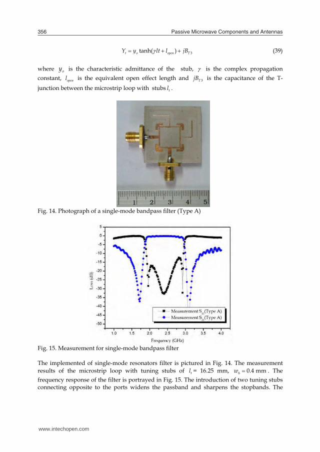
3tanh( )t o open TY y lt l jB (39)
where oy is the characteristic admittance of the stub, is the complex propagation constant, openl is the equivalent open effect length and 3TjB is the capacitance of the T-junction between the microstrip loop with stubs tl .
Fig. 14. Photograph of a single-mode bandpass filter (Type A)
Fig. 15. Measurement for single-mode bandpass filter The implemented of single-mode resonators filter is pictured in Fig. 14. The measurement results of the microstrip loop with tuning stubs of tl = 16.25 mm, 6 0.4 mmw . The frequency response of the filter is portrayed in Fig. 15. The introduction of two tuning stubs connecting opposite to the ports widens the passband and sharpens the stopbands. The
single-mode filter exhibits the 3-dB fractional bandwidth of the filter is 37%, the insertion loss better than 0.26 dB and return loss greater than 12.6 dB in the passband. In fact, this approach can be interpreted as using two stopbands induced by two tuning stubs in conjunction with the wide passband. In some cases, an undesired passband below the main passband may require a high passband section to be employed in conjunction with this proposing approach.
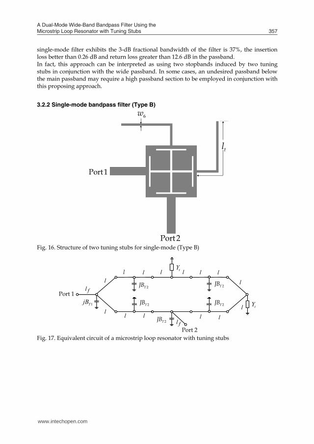
3.2.2 Single-mode bandpass filter (Type B)
Port1
Port 2
tl
6w
Fig. 16. Structure of two tuning stubs for single-mode (Type B)
fl
fl
l
l
Port 2
Port 11TjB
l
ll l l
l
l
lll
2TJB
2TJB
2TJB
2TJB 2TJB
l ltY
tY
Fig. 17. Equivalent circuit of a microstrip loop resonator with tuning stubs
www.intechopen.com
A Dual-Mode Wide-Band Bandpass Filter Using the Microstrip Loop Resonator with Tuning Stubs 357
3tanh( )t o open TY y lt l jB (39)
where oy is the characteristic admittance of the stub, is the complex propagation constant, openl is the equivalent open effect length and 3TjB is the capacitance of the T-junction between the microstrip loop with stubs tl .
Fig. 14. Photograph of a single-mode bandpass filter (Type A)
Fig. 15. Measurement for single-mode bandpass filter The implemented of single-mode resonators filter is pictured in Fig. 14. The measurement results of the microstrip loop with tuning stubs of tl = 16.25 mm, 6 0.4 mmw . The frequency response of the filter is portrayed in Fig. 15. The introduction of two tuning stubs connecting opposite to the ports widens the passband and sharpens the stopbands. The
single-mode filter exhibits the 3-dB fractional bandwidth of the filter is 37%, the insertion loss better than 0.26 dB and return loss greater than 12.6 dB in the passband. In fact, this approach can be interpreted as using two stopbands induced by two tuning stubs in conjunction with the wide passband. In some cases, an undesired passband below the main passband may require a high passband section to be employed in conjunction with this proposing approach.
3.2.2 Single-mode bandpass filter (Type B)
Port1
Port 2
tl
6w
Fig. 16. Structure of two tuning stubs for single-mode (Type B)
fl
fl
l
l
Port 2
Port 11TjB
l
ll l l
l
l
lll
2TJB
2TJB
2TJB
2TJB 2TJB
l ltY
tY
Fig. 17. Equivalent circuit of a microstrip loop resonator with tuning stubs
www.intechopen.com

Passive Microwave Components and Antennas358
Fig. 18. Photograph of a single-mode bandpass filter
Fig. 19. Measurement for single-mode bandpass filter Based on bandstop filter. The second resonator is modified by adding two tuning stubs connecting opposite to the ports. The resonator (Type B) with tuning stubs is shown in Fig 16. The length of tuning opened-stub is t gl /4. The equivalent circuit of resonator with tuning stubs is shown in Fig 17. The implemented of single-mode resonator filter is pictured in Fig. 18. The measurement results of the microstrip loop with tuning stubs of tl = 15.35 mm, 6 0.4 mmw . The frequency response of the filter is portrayed in Fig. 19. The introduction of two tuning stubs connecting opposite to the ports widens the passband and sharpens the stopbands. The
single-mode filter exhibits the 3-dB fractional bandwidth of the filter is 36%, the insertion loss better than 0.19 dB and return loss greater than 17 dB in the passband.
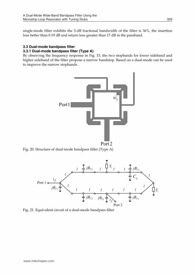
3.3 Dual-mode bandpass filter 3.3.1 Dual-mode bandpass filter (Type A) By observing the frequency response in Fig. 15, the two stopbands for lower sideband and higher sideband of the filter propose a narrow bandstop. Based on a dual-mode can be used to improve the narrow stopbands.
Port1
Port 2
pw
Fig. 20. Structure of dual-mode bandpass filter (Type A)
fl
fl
l
l
Port 2
Port 11TjB
2TjB 1TjB
tY
tYl 2TjB 2TjB
2TjB
ll l l l ll
l
lll
pC
Fig. 21. Equivalent circuit of a dual-mode bandpass filter
www.intechopen.com
A Dual-Mode Wide-Band Bandpass Filter Using the Microstrip Loop Resonator with Tuning Stubs 359
Fig. 18. Photograph of a single-mode bandpass filter
Fig. 19. Measurement for single-mode bandpass filter Based on bandstop filter. The second resonator is modified by adding two tuning stubs connecting opposite to the ports. The resonator (Type B) with tuning stubs is shown in Fig 16. The length of tuning opened-stub is t gl /4. The equivalent circuit of resonator with tuning stubs is shown in Fig 17. The implemented of single-mode resonator filter is pictured in Fig. 18. The measurement results of the microstrip loop with tuning stubs of tl = 15.35 mm, 6 0.4 mmw . The frequency response of the filter is portrayed in Fig. 19. The introduction of two tuning stubs connecting opposite to the ports widens the passband and sharpens the stopbands. The
single-mode filter exhibits the 3-dB fractional bandwidth of the filter is 36%, the insertion loss better than 0.19 dB and return loss greater than 17 dB in the passband.
3.3 Dual-mode bandpass filter 3.3.1 Dual-mode bandpass filter (Type A) By observing the frequency response in Fig. 15, the two stopbands for lower sideband and higher sideband of the filter propose a narrow bandstop. Based on a dual-mode can be used to improve the narrow stopbands.
Port1
Port 2
pw
Fig. 20. Structure of dual-mode bandpass filter (Type A)
fl
fl
l
l
Port 2
Port 11TjB
2TjB 1TjB
tY
tYl 2TjB 2TjB
2TjB
ll l l l ll
l
lll
pC
Fig. 21. Equivalent circuit of a dual-mode bandpass filter
www.intechopen.com
Passive Microwave Components and Antennas360
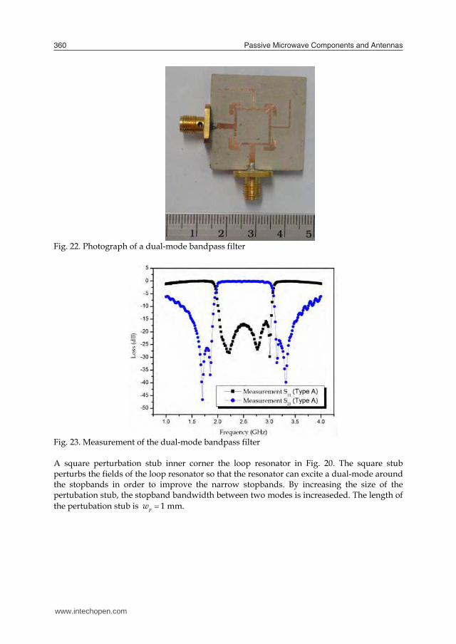
Fig. 22. Photograph of a dual-mode bandpass filter
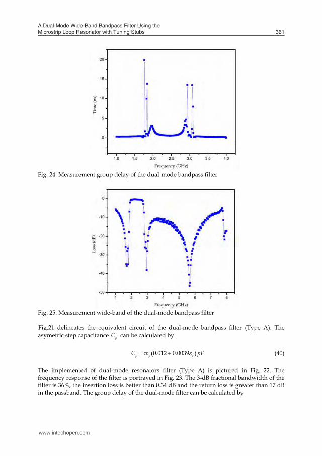
Fig. 23. Measurement of the dual-mode bandpass filter A square perturbation stub inner corner the loop resonator in Fig. 20. The square stub perturbs the fields of the loop resonator so that the resonator can excite a dual-mode around the stopbands in order to improve the narrow stopbands. By increasing the size of the pertubation stub, the stopband bandwidth between two modes is increaseded. The length of the pertubation stub is pw 1 mm.
Fig. 24. Measurement group delay of the dual-mode bandpass filter
Fig. 25. Measurement wide-band of the dual-mode bandpass filter Fig.21 delineates the equivalent circuit of the dual-mode bandpass filter (Type A). The asymetric step capacitance pC can be calculated by
(0.012 0.0039 )p p rC w pF (40) The implemented of dual-mode resonators filter (Type A) is pictured in Fig. 22. The frequency response of the filter is portrayed in Fig. 23. The 3-dB fractional bandwidth of the filter is 36%, the insertion loss is better than 0.34 dB and the return loss is greater than 17 dB in the passband. The group delay of the dual-mode filter can be calculated by
www.intechopen.com
A Dual-Mode Wide-Band Bandpass Filter Using the Microstrip Loop Resonator with Tuning Stubs 361
Fig. 22. Photograph of a dual-mode bandpass filter
Fig. 23. Measurement of the dual-mode bandpass filter A square perturbation stub inner corner the loop resonator in Fig. 20. The square stub perturbs the fields of the loop resonator so that the resonator can excite a dual-mode around the stopbands in order to improve the narrow stopbands. By increasing the size of the pertubation stub, the stopband bandwidth between two modes is increaseded. The length of the pertubation stub is pw 1 mm.
Fig. 24. Measurement group delay of the dual-mode bandpass filter
Fig. 25. Measurement wide-band of the dual-mode bandpass filter Fig.21 delineates the equivalent circuit of the dual-mode bandpass filter (Type A). The asymetric step capacitance pC can be calculated by
(0.012 0.0039 )p p rC w pF (40) The implemented of dual-mode resonators filter (Type A) is pictured in Fig. 22. The frequency response of the filter is portrayed in Fig. 23. The 3-dB fractional bandwidth of the filter is 36%, the insertion loss is better than 0.34 dB and the return loss is greater than 17 dB in the passband. The group delay of the dual-mode filter can be calculated by
www.intechopen.com

Passive Microwave Components and Antennas362
21S (41)
where 21S is the insertion-loss phase and is the frequency in radians per second. Fig. 24 shows the group delay of the filter. Within the passband, the group delay is below 2 ns. The measurement of wide-band response is shown in Fig. 25. Unlike the conventional structure of the wide-band filters using dual-mode ring resonators with tuning stubs, the filter exhibits a wide stopband due to four identical branches at the outer corner of the square loop and proposes the first spurious resonance frequency of the dispersion effect.
3.3.1 Dual-mode bandpass filter (Type B) By observing the frequency response in Fig. 19, the two stopbands for lower sideband and higher sideband of the filter propose a narrow bandstop. Based on a dual-mode can be used to improve the narrow stopbands.
Port 1
Port 2
dl
dw
Fig. 26. Structure of dual-mode bandpass filter (Type B)
fl
fl
l
l
Port 2
Port 11TjB
l
ll l l
l
l
lll
2TJB
2TJB
2TJB
2TJB 2TJB
l ltY
tY
dY
Fig. 27. Equivalent circuit of a dual-mode bandpass filter
Fig. 28. Photograph of a dual-mode bandpass filter A square perturbation stub outward corner the loop resonator in Fig. 26. The square stub perturbs the fields of the loop resonator so that the resonator can excite a dual-mode around the stopbands in order to improve the narrow stopbands. By increasing the size of the pertubation stub, the stopband bandwidth between two modes is increaseded. The length of the pertubation stub are dw = 0.7 mm and dl = 0.7 mm. Fig.27 delineates the equivalent circuit of the dual-mode bandpass filter. dY is the admittance reflecting into the pertubation stub. dY can be expressed by
3tanh( )d o d open TY y l l jB (42)
where oy is the characteristic admittance of the stub, is the complex propagation constant, openl is the equivalent open effect length and 3TjB is the capacitance of the junction between the microstrip loop with pertubation stub dl .
Fig. 29. Measurement of the dual-mode bandpass filter
www.intechopen.com

A Dual-Mode Wide-Band Bandpass Filter Using the Microstrip Loop Resonator with Tuning Stubs 363
21S (41)
where 21S is the insertion-loss phase and is the frequency in radians per second. Fig. 24 shows the group delay of the filter. Within the passband, the group delay is below 2 ns. The measurement of wide-band response is shown in Fig. 25. Unlike the conventional structure of the wide-band filters using dual-mode ring resonators with tuning stubs, the filter exhibits a wide stopband due to four identical branches at the outer corner of the square loop and proposes the first spurious resonance frequency of the dispersion effect.
3.3.1 Dual-mode bandpass filter (Type B) By observing the frequency response in Fig. 19, the two stopbands for lower sideband and higher sideband of the filter propose a narrow bandstop. Based on a dual-mode can be used to improve the narrow stopbands.
Port 1
Port 2
dl
dw
Fig. 26. Structure of dual-mode bandpass filter (Type B)
fl
fl
l
l
Port 2
Port 11TjB
l
ll l l
l
l
lll
2TJB
2TJB
2TJB
2TJB 2TJB
l ltY
tY
dY
Fig. 27. Equivalent circuit of a dual-mode bandpass filter
Fig. 28. Photograph of a dual-mode bandpass filter A square perturbation stub outward corner the loop resonator in Fig. 26. The square stub perturbs the fields of the loop resonator so that the resonator can excite a dual-mode around the stopbands in order to improve the narrow stopbands. By increasing the size of the pertubation stub, the stopband bandwidth between two modes is increaseded. The length of the pertubation stub are dw = 0.7 mm and dl = 0.7 mm. Fig.27 delineates the equivalent circuit of the dual-mode bandpass filter. dY is the admittance reflecting into the pertubation stub. dY can be expressed by
3tanh( )d o d open TY y l l jB (42)
where oy is the characteristic admittance of the stub, is the complex propagation constant, openl is the equivalent open effect length and 3TjB is the capacitance of the junction between the microstrip loop with pertubation stub dl .
Fig. 29. Measurement of the dual-mode bandpass filter
www.intechopen.com
Passive Microwave Components and Antennas364
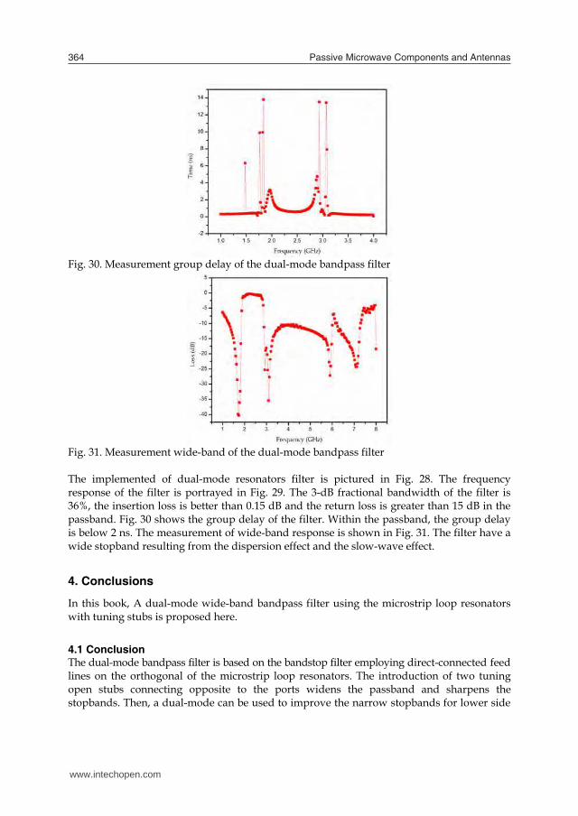
Fig. 30. Measurement group delay of the dual-mode bandpass filter
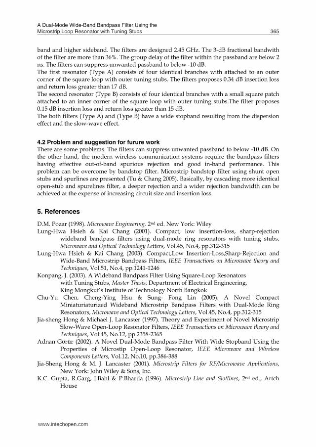
Fig. 31. Measurement wide-band of the dual-mode bandpass filter The implemented of dual-mode resonators filter is pictured in Fig. 28. The frequency response of the filter is portrayed in Fig. 29. The 3-dB fractional bandwidth of the filter is 36%, the insertion loss is better than 0.15 dB and the return loss is greater than 15 dB in the passband. Fig. 30 shows the group delay of the filter. Within the passband, the group delay is below 2 ns. The measurement of wide-band response is shown in Fig. 31. The filter have a wide stopband resulting from the dispersion effect and the slow-wave effect.
4. Conclusions
In this book, A dual-mode wide-band bandpass filter using the microstrip loop resonators with tuning stubs is proposed here.
4.1 Conclusion The dual-mode bandpass filter is based on the bandstop filter employing direct-connected feed lines on the orthogonal of the microstrip loop resonators. The introduction of two tuning open stubs connecting opposite to the ports widens the passband and sharpens the stopbands. Then, a dual-mode can be used to improve the narrow stopbands for lower side
band and higher sideband. The filters are designed 2.45 GHz. The 3-dB fractional bandwith of the filter are more than 36%. The group delay of the filter within the passband are below 2 ns. The filters can suppress unwanted passband to below -10 dB. The first resonator (Type A) consists of four identical branches with attached to an outer corner of the square loop with outer tuning stubs. The filters proposes 0.34 dB insertion loss and return loss greater than 17 dB. The second resonator (Type B) consists of four identical branches with a small square patch attached to an inner corner of the square loop with outer tuning stubs.The filter proposes 0.15 dB insertion loss and return loss greater than 15 dB. The both filters (Type A) and (Type B) have a wide stopband resulting from the dispersion effect and the slow-wave effect.
4.2 Problem and suggestion for furure work There are some problems. The filters can suppress unwanted passband to below -10 dB. On the other hand, the modern wireless communication systems require the bandpass filters having effective out-of-band spurious rejection and good in-band performance. This problem can be overcome by bandstop filter. Microstrip bandstop filter using shunt open stubs and spurlines are presented (Tu & Chang 2005). Basically, by cascading more identical open-stub and spurelines filter, a deeper rejection and a wider rejection bandwidth can be achieved at the expense of increasing circuit size and insertion loss.
5. References
D.M. Pozar (1998). Microwave Engineering, 2nd ed. New York: Wiley Lung-Hwa Hsieh & Kai Chang (2001). Compact, low insertion-loss, sharp-rejection
wideband bandpass filters using dual-mode ring resonators with tuning stubs, Microwave and Optical Technology Letters, Vol.45, No.4, pp.312-315
Lung-Hwa Hsieh & Kai Chang (2003). Compact,Low Insertion-Loss,Sharp-Rejection and Wide-Band Microstrip Bandpass Filters, IEEE Transactions on Microwave theory and Techniques, Vol.51, No.4, pp.1241-1246
Konpang, J. (2003). A Wideband Bandpass Filter Using Square-Loop Resonators with Tuning Stubs, Master Thesis, Department of Electrical Engineering, King Mongkut’s Institute of Technology North Bangkok
Chu-Yu Chen, Cheng-Ying Hsu & Sung- Fong Lin (2005). A Novel Compact Miniaturiaturized Wideband Microstrip Bandpass Filters with Dual-Mode Ring Resonators, Microwave and Optical Technology Letters, Vol.45, No.4, pp.312-315
Jia-sheng Hong & Michael J. Lancaster (1997). Theory and Experiment of Novel Microstrip Slow-Wave Open-Loop Resonator Filters, IEEE Transactions on Microwave theory and Techniques, Vol.45, No.12, pp.2358-2365
Adnan Görür (2002). A Novel Dual-Mode Bandpass Filter With Wide Stopband Using the Properties of Microstip Open-Loop Resonator, IEEE Microwave and Wireless Components Letters, Vol.12, No.10, pp.386-388
Jia-Sheng Hong & M. J. Lancaster (2001). Microstrip Filters for RF/Microwave Applications, New York: John Wiley & Sons, Inc.
K.C. Gupta, R.Garg, I.Bahl & P.Bhartia (1996). Microstrip Line and Slotlines, 2nd ed., Artch House
www.intechopen.com
A Dual-Mode Wide-Band Bandpass Filter Using the Microstrip Loop Resonator with Tuning Stubs 365
Fig. 30. Measurement group delay of the dual-mode bandpass filter
Fig. 31. Measurement wide-band of the dual-mode bandpass filter The implemented of dual-mode resonators filter is pictured in Fig. 28. The frequency response of the filter is portrayed in Fig. 29. The 3-dB fractional bandwidth of the filter is 36%, the insertion loss is better than 0.15 dB and the return loss is greater than 15 dB in the passband. Fig. 30 shows the group delay of the filter. Within the passband, the group delay is below 2 ns. The measurement of wide-band response is shown in Fig. 31. The filter have a wide stopband resulting from the dispersion effect and the slow-wave effect.
4. Conclusions
In this book, A dual-mode wide-band bandpass filter using the microstrip loop resonators with tuning stubs is proposed here.
4.1 Conclusion The dual-mode bandpass filter is based on the bandstop filter employing direct-connected feed lines on the orthogonal of the microstrip loop resonators. The introduction of two tuning open stubs connecting opposite to the ports widens the passband and sharpens the stopbands. Then, a dual-mode can be used to improve the narrow stopbands for lower side
band and higher sideband. The filters are designed 2.45 GHz. The 3-dB fractional bandwith of the filter are more than 36%. The group delay of the filter within the passband are below 2 ns. The filters can suppress unwanted passband to below -10 dB. The first resonator (Type A) consists of four identical branches with attached to an outer corner of the square loop with outer tuning stubs. The filters proposes 0.34 dB insertion loss and return loss greater than 17 dB. The second resonator (Type B) consists of four identical branches with a small square patch attached to an inner corner of the square loop with outer tuning stubs.The filter proposes 0.15 dB insertion loss and return loss greater than 15 dB. The both filters (Type A) and (Type B) have a wide stopband resulting from the dispersion effect and the slow-wave effect.
4.2 Problem and suggestion for furure work There are some problems. The filters can suppress unwanted passband to below -10 dB. On the other hand, the modern wireless communication systems require the bandpass filters having effective out-of-band spurious rejection and good in-band performance. This problem can be overcome by bandstop filter. Microstrip bandstop filter using shunt open stubs and spurlines are presented (Tu & Chang 2005). Basically, by cascading more identical open-stub and spurelines filter, a deeper rejection and a wider rejection bandwidth can be achieved at the expense of increasing circuit size and insertion loss.
5. References
D.M. Pozar (1998). Microwave Engineering, 2nd ed. New York: Wiley Lung-Hwa Hsieh & Kai Chang (2001). Compact, low insertion-loss, sharp-rejection
wideband bandpass filters using dual-mode ring resonators with tuning stubs, Microwave and Optical Technology Letters, Vol.45, No.4, pp.312-315
Lung-Hwa Hsieh & Kai Chang (2003). Compact,Low Insertion-Loss,Sharp-Rejection and Wide-Band Microstrip Bandpass Filters, IEEE Transactions on Microwave theory and Techniques, Vol.51, No.4, pp.1241-1246
Konpang, J. (2003). A Wideband Bandpass Filter Using Square-Loop Resonators with Tuning Stubs, Master Thesis, Department of Electrical Engineering, King Mongkut’s Institute of Technology North Bangkok
Chu-Yu Chen, Cheng-Ying Hsu & Sung- Fong Lin (2005). A Novel Compact Miniaturiaturized Wideband Microstrip Bandpass Filters with Dual-Mode Ring Resonators, Microwave and Optical Technology Letters, Vol.45, No.4, pp.312-315
Jia-sheng Hong & Michael J. Lancaster (1997). Theory and Experiment of Novel Microstrip Slow-Wave Open-Loop Resonator Filters, IEEE Transactions on Microwave theory and Techniques, Vol.45, No.12, pp.2358-2365
Adnan Görür (2002). A Novel Dual-Mode Bandpass Filter With Wide Stopband Using the Properties of Microstip Open-Loop Resonator, IEEE Microwave and Wireless Components Letters, Vol.12, No.10, pp.386-388
Jia-Sheng Hong & M. J. Lancaster (2001). Microstrip Filters for RF/Microwave Applications, New York: John Wiley & Sons, Inc.
K.C. Gupta, R.Garg, I.Bahl & P.Bhartia (1996). Microstrip Line and Slotlines, 2nd ed., Artch House
www.intechopen.com

Passive Microwave Components and Antennas366
Konpang, J.; Jumneansri, C.; Anunvrapong, P.; & Wongmethanukroah, J.; (2007). A dual-mode wide-band bandpass filter using the microstrip loop resonator with tuning stubs, Microwave Conference, 2007. European, pp. 791-794
Konpang, J. (2008). A dual-mode wide-band bandpass filter using slotted patch resonator with tuning stubs, Microwave Conference, 2008. APMC 2008. Asia-Pacific, pp.1-4
Wen-Hua Tu & Kai Chang (2005). Compact Microstip Filter Using Open Stub and Spurline, IEEE Microwave and Wireless Components Letters, Vol.15, No.4, pp.268-270
IE3D Version 8, (2001). Zeland Software, Inc., Fremont, CA
www.intechopen.com

Passive Microwave Components and AntennasEdited by Vitaliy Zhurbenko
ISBN 978-953-307-083-4Hard cover, 556 pagesPublisher InTechPublished online 01, April, 2010Published in print edition April, 2010
InTech EuropeUniversity Campus STeP Ri Slavka Krautzeka 83/A 51000 Rijeka, Croatia Phone: +385 (51) 770 447 Fax: +385 (51) 686 166www.intechopen.com
InTech ChinaUnit 405, Office Block, Hotel Equatorial Shanghai No.65, Yan An Road (West), Shanghai, 200040, China
Phone: +86-21-62489820 Fax: +86-21-62489821
Modelling and computations in electromagnetics is a quite fast-growing research area. The recent interest inthis field is caused by the increased demand for designing complex microwave components, modelingelectromagnetic materials, and rapid increase in computational power for calculation of complexelectromagnetic problems. The first part of this book is devoted to the advances in the analysis techniquessuch as method of moments, finite-difference time- domain method, boundary perturbation theory, Fourieranalysis, mode-matching method, and analysis based on circuit theory. These techniques are considered withregard to several challenging technological applications such as those related to electrically large devices,scattering in layered structures, photonic crystals, and artificial materials. The second part of the book dealswith waveguides, transmission lines and transitions. This includes microstrip lines (MSL), slot waveguides,substrate integrated waveguides (SIW), vertical transmission lines in multilayer media as well as MSL to SIWand MSL to slot line transitions.
How to referenceIn order to correctly reference this scholarly work, feel free to copy and paste the following:
Jessada Konpang (2010). A Dual-Mode Wide-Band Bandpass Filter Using the Microstrip Loop Resonator withTuning Stubs, Passive Microwave Components and Antennas, Vitaliy Zhurbenko (Ed.), ISBN: 978-953-307-083-4, InTech, Available from: http://www.intechopen.com/books/passive-microwave-components-and-antennas/a-dual-mode-wide-band-bandpass-filter-using-the-microstrip-loop-resonator-with-tuning-stubs

© 2010 The Author(s). Licensee IntechOpen. This chapter is distributedunder the terms of the Creative Commons Attribution-NonCommercial-ShareAlike-3.0 License, which permits use, distribution and reproduction fornon-commercial purposes, provided the original is properly cited andderivative works building on this content are distributed under the samelicense.