jeppiaar engineering college department of...
TRANSCRIPT

JEPPIAAR ENGINEERING COLLEGE DEPARTMENT OF ELECTRICAL AND ELECTRONICS ENGINEERING
VISION OF INSTITUTION
To build Jeppiaar Engineering College as an institution of academic excellence in technology and
management education, leading to become a world class University.
MISSION OF INSTITUTION
To excel in teaching and learning, research and innovation by promoting the principles of scientific
analysis and creative thinking.
To participate in the production, development, dissemination of knowledge and interact with national
and international communities.
To equip students with ethical values, and life skills that would enrich their lives and enable them to
meaningfully contribute to the progress of the society.
To prepare students for higher studies and lifelong learning, enrich them with the practical and
entrepreneurial skills necessary to excel as future professionals and contribute to Nation’s economy.
PROGRAM OUTCOMES (POs)
1 Engineering knowledge: Apply the knowledge of mathematics, science, engineering
fundamentals, and an engineering specialization to the solution of complex engineering problems.
2 Problem analysis: Identify, formulate, review research literature, and analyze complex
engineering problems reaching substantiated conclusions using first principles of
mathematics, natural sciences, and engineering sciences.
3 Design/development of solutions: Design solutions for complex engineering problems
and design system components or processes that meet the specified needs with appropriate
consideration for the public health and safety, and the cultural, societal, and environmental
considerations
4 Conduct investigations of complex problems: Use research-based knowledge and
research methods including design of experiments, analysis and interpretation of data, and
synthesis of the information to provide valid conclusions.
5 Modern tool usage: Create, select, and apply appropriate techniques, resources, and
modern engineering and IT tools including prediction and modeling to complex engineering
activities with an understanding of the limitations.
6 The engineer and society: Apply reasoning informed by the contextual knowledge to
assess societal, health, safety, legal and cultural issues and the consequent responsibilities
relevant to the professional engineering practice.
7 Environment and sustainability: Understand the impact of the professional engineering
solutions in societal and environmental contexts, and demonstrate the knowledge of, and
need for sustainable development.
8 Ethics: Apply ethical principles and commit to professional ethics and responsibilities and
norms of the engineering practice.
9 Individual and team work: Function effectively as an individual, and as a member or
leader in diverse teams, and in multidisciplinary settings.
10 Communication: Communicate effectively on complex engineering activities with the
engineering community and with society at large, such as, being able to comprehend and
write effective reports and design documentation, make effective presentations, and give and
receive clear instructions.
11 Project management and finance: Demonstrate knowledge and understanding of the
engineering and management principles and apply these to one’s own work, as a member
and leader in a team, to manage projects and in multidisciplinary environments.
12 Life-long learning: Recognize the need for, and have the preparation and ability to engage
in independent and life-long learning in the broadest context of technological change.
VISION OF THE DEPARTMENT
The Department of Electrical and Electronics Engineering strives to be a Centre of Excellence in
education and technical research, in the endeavour of which the Department will continually update the teaching
methodologies, progress in the emerging technologies and continue to play a vital role in the development of the
society.
MISSION OF THE DEPARTMENT
M1 To develop the ability to learn and work creatively that would enhance the ability of both
students and faculty to do innovative research.
M2 To create and maintain state-of-the art facilities which provide students and faculty with
opportunities to analyse, apply and disseminate knowledge globally.
M3
To impart the knowledge in essential interdisciplinary fields which will enhance the
interpersonal skills, team work, professional ethics and make them work effectively for
their own benefit and the betterment of the society.
M4 Prepare students for lifelong learning of theoretical and practical concepts to face
intellectual, economical and career challenges.
PROGRAM EDUCATIONAL OBJECTIVES (PEOs)
PEO 01 Strengthen the knowledge in Electrical and Electronics Engineering to enable them work
for modern industries by promoting energy conservation and sustainability.
PEO 02 Enrich analytical, creative and critical logical reasoning skills to solve problems faced by
emerging domains of electrical and electronics engineering industries worldwide.
PEO 03
Develop effective communication and inter-personal skills to work with enhanced team
spirit in multidisciplinary projects with a broader ethical, professional, economical and
social perspective.
PEO 04 Prepare the students either to establish start ups or to pursue higher education at reputed
institutions.
PROGRAM SPECIFIC OUTCOME (PSOs)
PSO 1
Professional Skills:
Apply the knowledge of Mathematics, Science and Engineering to solve real time problems in
the field of Power Electronics, Electrical Drives, Power Systems, Control Systems and
Instrumentation.
PSO 2
Research and Innovation:
Analyze and synthesize circuits by solving complex engineering problems to obtain the
optimal solution using effective software tools and hardware prototypes in the field of
robotics and renewable energy systems.
PSO 3
Product development: Develop concepts and products by applying ideas of electrical domain into other diversified
engineering domains.
EE8301 ELECTRICAL MACHINES – I LT P C
3 1 0 4 OBJECTIVES: To impart knowledge on the following Topics
Magnetic-circuit analysis and introduce magnetic materials
Constructional details, the principle of operation, prediction of performance, the methods of testing the transformers and three phase transformer connections..
Working principles of electrical machines using the concepts of electromechanical energy conversion principles and derive expressions for generated voltage and torque developed in all Electrical Machines.
Working principles of DC machines as Generator types, determination of their noload/ load characteristics, starting and methods of speed control of motors.
Various losses taking place in D.C. Motor and to study the different testing methods to arrive at their
performance.
UNIT I MAGNETIC CIRCUITS AND MAGNETIC MATERIALS 9 Magnetic circuits –Laws governing magnetic circuits - Flux linkage, Inductance and energy – Statically and
Dynamically induced EMF - Torque – Properties of magnetic materials, Hysterisis and Eddy Current losses - AC
excitation, introduction to permanent magnets-Transformer as a magnetically coupled circuit.
UNIT II TRANSFORMERS 9 Construction – principle of operation – equivalent circuit parameters – phasor diagrams, losses – testing –
efficiency and voltage regulation-all day efficiency-Sumpner‟s test, per unit representation – inrush current -
three phase transformers-connections – Scott Connection – Phasing of transformer– parallel operation of three
phase transformers-auto transformer – tap changing transformers- tertiary winding.
UNIT III ELECTROMECHANICAL ENERGY CONVERSION AND CONCEPTS IN ROTATING MACHINES 9 Energy in magnetic system – Field energy and coenergy-force and torque equations – singly and multiply
excited magnetic field systems-mmf of distributed windings – Winding Inductances-, magnetic fields in rotating
machines – rotating mmf waves – magnetic saturation and leakage fluxes.
UNIT IV DC GENERATORS 9 Construction and components of DC Machine – Principle of operation - Lap and wave windings-EMF equations–
circuit model – armature reaction –methods of excitation-commutation and interpoles - compensating winding –
characteristics of DC generators.
UNIT V DC MOTORS 9 Principle and operations - types of DC Motors – Speed Torque Characteristics of DC Motors-starting and speed control of DC motors –Plugging, dynamic and regenerative braking- testing and efficiency– Retardation test- Swinburne‟s test and Hopkinson‟s test - Permanent magnet dc motors(PMDC)-DC Motor applications. TOTAL (L: 45+T: 15): 60 PERIODS OUTCOMES:
Ability to analyze the magnetic-circuits. Ability to acquire the knowledge in constructional details of transformers. Ability to understand the concepts of electromechanical energy conversion. Ability to acquire the knowledge in working principles of DC Generator. Ability to acquire the knowledge in working principles of DC Motor
Ability to acquire the knowledge in various losses taking place in D.C. MachinesTEXT BOOKS: 1. Stephen J. Chapman, „Electric Machinery Fundamentals‟4
th edition, McGraw Hill Education Pvt. Ltd, 2010.
2. P.C. Sen „Principles of Electric Machines and Power Electronics‟ John Wiley & Sons; 3rd Edition 2013.
3. Nagrath I. J and Kothari D. P. „Electric Machines‟, Fourth Edition, Tata McGraw Hill Publishing Company Ltd, 2010.
REFERENCES: 1. Theodore Wildi, “Electrical Machines, Drives, and Power Systems”, Pearson Education., (5
th Edition), 2002.
2. B.R. Gupta,‟Fundamental of Electric Machines‟ New age International Publishers,3rd Edition ,Reprint 2015. 3. S.K. Bhattacharya, „Electrical Machines‟ McGraw - Hill Education, New Delhi, 3
rd Edition, 2009.
4. Vincent Del Toro, „Basic Electric Machines‟ Pearson India Education, 2016

5. Surinder Pal Bali, „Electrical Technology Machines & Measurements, Vol.II, Pearson, 2013 6. Fitzgerald. A.E., Charles Kingsely Jr, Stephen D.Umans, „Electric Machinery‟, Sixth edition, Tata McGraw Hill
Books Company, 2003. 7. B.L.Theraja., “Electrical Technology” S.Chand publications Pvt. Ltd., New Delhi, 2011.
Course Code& Name: EE8301 ELECTRICAL MACHINES I Degree/Programme: B.E/EEE Semester: III Section: A, B
Duration: JUNE 2018 – DEC 2018 Regulation: 2017/AUC
Name of the Staff:
AIM: To model and analyze electrical apparatus and their application to power system
OBJECTIVES: To impart knowledge on the following Topics
Magnetic-circuit analysis and introduce magnetic materials
Constructional details, the principle of operation, prediction of performance, the methods of testing the transformers and three phase transformer connections..
Working principles of electrical machines using the concepts of electromechanical energy conversion principles and derive expressions for generated voltage and torque developed in all Electrical Machines.
Working principles of DC machines as Generator types, determination of their noload/ load characteristics, starting and methods of speed control of motors.
Various losses taking place in D.C. Motor and to study the different testing methods to arrive at their
performance.
COURSE OUTCOMES:
C Course Outcomes
C2 10.1 Understand the techniques of magnetic-circuit analysis and introduce magnetic materials
C2 10.2 Understand the constructional details, the principle of operation, prediction of performance, the
methods of testing the transformers and three phase transformer connections
C2 10.3 Understand the working principles of electrical machines using the concepts of electromechanical energy conversion principle and derive expressions for generated voltage and torque developed in all rotating machines C2 10.4 Understand the working principles of dc machines as generator determination of their no load /load
characteristics.
C2 10.5 Understand the working principles of dc motor types, characteristics, braking and testing.
Mapping of Course Outcomes(COs), Course(C),ProgramSpecificOutcomes (PSOs)with Program Outcomes. (POs)– [Levels of correlation:3 (High),2 (Medium), 1(Low)]
Course PO1 PO2 PO3 PO4 PO5 PO6 PO7 PO8 PO9 PO10 PO11 PO12 PSO1 PSO2 PSO3

C2 10.1 3 2 3 2 - - - - - - 2 2 3 - 2
C2 10.2 3 2 3 2 - - - - - - 1 - 3 - 1
C2 10.3 3 2 3 2 - - - - - - - 2 3 1 2
C2 10.4 3 2 3 2 - - - - - - 1 - 3 2 2
C2 10.5 3 2 3 2 - - - - - - 2 - 3 2 2
UNIT – I MAGNETIC CIRCUITS AND MAGNETIC MATERIALS Target Periods: 9
Sl N o Contents CO
Statement
Book Reference &
Page No
Delivery method
Delivery Periods
Knowledge Level
1 Magnetic circuits C2 10.1 TB1:11-12 Chalk &
board / PPT 1
R & U
2 Laws governing magnetic circuits C2 10.1 TB1:31 Chalk &
board / PPT 1 R & U
3 Flux linkage, Inductance and energy C2 10.1 TB1:30-30 Chalk &
board / PPT 1 R, U, An
4 Statically and Dynamically induced EMF C2 10.1 TB1:32 Chalk & board / PPT 2
R, U, An
5 Torque C2 10.1 TB1:32 Chalk &
board / PPT 1 R, U, An
6 Hysteresis and Eddy Current losses C2 10.1 TB2:36-37 Chalk &
board / PPT 2 R,U, A
7 AC excitation, introduction to permanent
magnets C2 10.1 TB: 39-40 Chalk &
board / PPT 2 An, E
8 Transformer as a magnetically Coupled circuit
C2 10.1 TB2:42 Chalk &
board / PPT 2
R, U, An
UNIT II TRANSFORMERS Target Periods:9
Sl No Contents CO
Statement
Book Reference &
Page No
Delivery method
Delivery Hrs
Knowledge Level
1 Construction C2 10.2 TB1:53 Chalk &
board / PPT 1 R, A, An
2 Principle of operation C2 10.2
TB1:60-62
Chalk &
board / PPT
1
R, U, A, An
3 Equivalent circuit parameters C2 10.2
TB1:68-73
Chalk &
board / PPT
1
R, U, A, An

4 Phasor diagrams C2 10.2 TB1:76-77 Chalk & board / PPT 1 R, U, A, An
5 Losses C2 10.2 TB1:79 Chalk &
board / PPT
1
R, U, A, An
6 Testing C2 10.2 TB1: 79-86 Chalk &
board / PPT
2
R, A, An
7 Efficiency and voltage regulation-all day
efficiency-Sumpner’s test, per unit
representation
C2 10.2 TB1:91-101 Chalk &
board / PPT 1 A, An, E
8 Inrush current C2 10.2 TB1:102-104 Chalk & board / PPT
1
R, U, A, An
9
Three phase transformers-connections –
Scott Connection – Phasing of
transformer–parallel operation of three
phase transformers
C2 10.2 TB1:111-116 Chalk & board / PPT
1
R, A, An
10 Auto transformer – tap changing
transformers C2 10.2 TB1:104, 140
Chalk &
board / PPT 1 A, An, E
11 Tertiary winding C2 10.2 TB1:133
Chalk &
board / PPT 1 R, U
UNIT III ELECTROMECHANICAL ENERGY CONVERSION
AND CONCEPTS IN ROTATING MACHINES Target Periods: 9
Sl No Contents CO
Statement
Book Reference &
Page No
Delivery method
Delivery Hrs
Knowledge Level
1 Energy in magnetic system
C2 10.3 RB1:157-159 Chalk &
board / PPT 1
R, U, An
2 Field energy and coenergy-force and
torque equations C2 10.3 RB1:161-162
Chalk &
board / PPT 2
R, U, A, An
3 singly and excited magnetic field systems C2 10.3 RB1:161-165
Chalk &
board / PPT 2
R, U, A, An
4 Mmf of distributed windings C2 10.3 RB1:225-232 Chalk & board / PPT 1
R, A,
5 Winding Inductances C2 10.3 RB1:259-263 Chalk &
board / PPT 1 R, U, A,
6 Magnetic fields in rotating machines C2 10.3 RB1:233-235 Chalk &
board / PPT 2 R, U, A, An
7 rotating mmf waves C2 10.3 RB1:233-235 Chalk &
board / PPT 2 R, U, A, An
8 Magnetic saturation and leakage fluxes. C2 10.3 RB1:15-16
Chalk &
board / PPT 1 R, U, An
UNIT IV DC GENERATORS Target Periods:9
Sl No Contents CO
Statement Book Reference
& Page No
Delivery
method
Delivery
Hrs
Knowledge
Level
1 Principle of operation C2 10.4 RB2:888-890 Chalk &
board / PPT
1 R, U
2 Construction and components of DC
Machine C2 10.4
RB2:890-895 Chalk & board /
PPT 2
R, U, A, An
3 Lap and wave windings C2 10.4 RB2:896-910 Chalk &
board / PPT
2 R, U, A, An
4 Circuit model C2 10.4 RB2:911-914 Chalk &
board /
PPT 1
R, U, A, An
5 EMF equations C2 10.4 RB2:914-924 Chalk &
board / PPT
1 R, U, A, An
6 Armature reaction C2 10.4 RB2:938-945 Chalk &
board / PPT
1 R, U, A, An
7 Methods of excitation C2 10.4 RB2:938-945 Chalk &
board /
PPT 1
R, U, A, An
8 Commutation and interpoles C2 10.4 RB2:946-951 Chalk &
board /
PPT 1
R, U, A, An
9 Compensating winding C2 10.4 RB2: 946-951 Chalk &
board /
PPT 1
R, U, A, An
10 Characteristics of DC generators C2 10.4 RB2:968-978 Chalk &
board /
PPT
1 R, U, A, An
UNIT V DC MOTORS Target Periods: 9
Sl No Contents CO
Statement
Book Reference
& Page No
Delivery method
Delivery Hrs
Knowledge Level
1 Principle and operations C2 10.5
TB2:996-1014 Chalk & board /
PPT 2 R, U, A, An
2 Types of DC Motors C2 10.5
TB2:1015-1027 Chalk & board /
PPT 1 R, U, A, An
3 Speed Torque Characteristics of DC
Motors C2 10.5
TB2:1031-1061 Chalk & board / PPT 2
R, U, A, An
4 Starting and speed control of DC motors C2 10.5
TB2:1061-1031 Chalk & board / PPT 1 R, U, A, An
5 Plugging, dynamic and regenerative
braking C2 10.5
TB2:1062-1073 Chalk & board /
PPT 1 R, U, A, An
6 Testing and efficiency C2 10.5
TB2:1092-1111 Chalk & board /
PPT 1 R, U, A, An

7 Retardation test C2 10.5
TB2:1092-1111 Chalk & board /
PPT 1 R, U, A, An
8 Swinburne’s test and Hopkinson’s test C2 10.5
TB2:1092-1111 Chalk & board /
PPT 1 R, U, A, An
9 Permanent magnet dc motors(PMDC) C2 10.5
TB2:1547-1549 Chalk & board /
PPT 1 R, U, A, An
10 DC Motor applications C2 10.5
TB2:1021 Chalk & board /
PPT 1 R, U, A, An
R- Remember, U- Understand, A- Apply, An- Analyze, E- Evaluate & C- Create.
Books:Text/Reference:
S.No Title of the Book Author Publisher Year
1 TB1 Electric Machines Nagrath I. J and
Kothari D. P.
Tata McGraw Hill Publishing
Company Ltd, Fourth Edition 2010
2 RB1 Electric Technology B.L.Theraja S.Chand publications Pvt. Ltd., New Delhi
2011
Comments Given by the Scrutinizing Committee Members
Signature of the Scrutinizing
Signature of the HOD
EE6401 ELECTRICAL MACHINES – I
UNIT –I
MAGNETIC CIRCUITS AND MAGNETIC MATERIALS
PART: A
1. Explain statically induced EMF ?April/May 2015 Self-Induced EMF is that EMF which is induced in the conductor by changing in its
own. When current is changing the magnetic field is also changing around the coil and
hence Faraday’s law is applied here and EMF are induced in the coil to its self which
called self-induced EMF.
2. State Ampere’s Law. May/June 2016 Ampere's Law states that for any closed loop path, the sum of the length elements
times the magnetic field in the direction of the length element is equal to the permeability
times the electric current enclosed in the loop.
3. Prepare the list of the materials suitable for fabrication of Permanent Magnets. April/May 2015
Alnico alloy, Stontinum, neodymium and iron boron
4. What are quasi-static? May/June 2014 All the electromechanical energy conversion devices are slow because of the inertia
associated with the moving parts. Thereforth field in the device is also slow in nature i.e
Quasistatic field. And there is no time lag between exciting current and the establishment of
magnetic flux
5. Define Magnetic reluctance. May/June 2014 The opposition that the magnetic circuit offers to flux is called reluctance. It is
expressed as the ratio of MMF to flux. It is denoted by S and its unit is AT/m
6. Define Flux linkage. Nov/Dec 2013 A magnetic field going through a coil of wire has a property known as flux linkage. This
is the product of the flux Φ and the number of coils in the wire N.
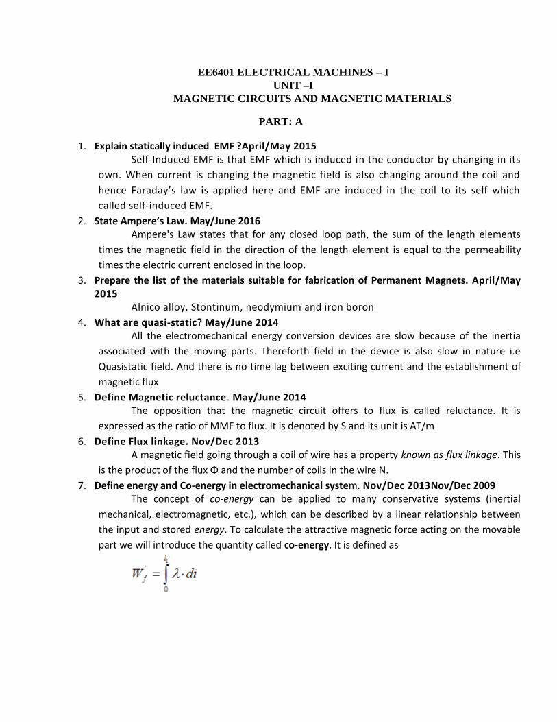
7. Define energy and Co-energy in electromechanical system. Nov/Dec 2013Nov/Dec 2009 The concept of co-energy can be applied to many conservative systems (inertial
mechanical, electromagnetic, etc.), which can be described by a linear relationship between
the input and stored energy. To calculate the attractive magnetic force acting on the movable
part we will introduce the quantity called co-energy. It is defined as
8. Classify the basic type so for rating electric machines? May/June 2013 April/May 2011
1.DC machines
2.AC machines
3.Special machines
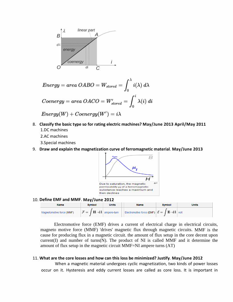
9. Draw and explain the magnetization curve of ferromagnetic material. May/June 2013
10. Define EMF and MMF. May/June 2012
Electromotive force (EMF) drives a current of electrical charge in electrical circuits,
magneto motive force (MMF) 'drives' magnetic flux through magnetic circuits. MMF is the
cause for producing flux in a magnetic circuit. the amount of flux setup in the core decent upon
current(I) and number of turns(N). The product of NI is called MMF and it determine the
amount of flux setup in the magnetic circuit MMF=NI ampere turns (AT)
11. What are the core losses and how can this loss be minimized? Justify. May/June 2012 When a magnetic material undergoes cyclic magnetization, two kinds of power losses
occur on it. Hysteresis and eddy current losses are called as core loss. It is important in

determining heating, temperature rise, rating & efficiency of transformers, machines &other
A.C run magnetic devices.
Hysteresis losses can be reduced by selecting suitable core having small area of B-H
loop curve and eddy current losses can be reduced by laminating the core.
12. Distinguish statically and dynamically induced EMF. Nov/Dec 2011 Nov Dec 2010
Static EMF
The emf induced in a stationary conductor due to alternating magnetic field is statically
induced emf.
Dynamic EMF
The emf induced in the moving conductor due to stationary flux is called dynamically induced
EMF.
13. What is the Hysteresis loss and how can this loss be minimized? Nov/Dec 2011.
Hysteresis loss
The magnetic field intensity [H] is increased from zero to maximum and the energy is stored
Now again the H is reduced to zero, dB is negative ,the energy is given out by the magnetic
field .The net energy lost due this in the form of heat and is called as hysteresis loss.
Eddy Current loss : When a magnetic core carries time –varying flux,voltages are induced in all
possible paths enclosing the flux.The result is the production of circulating current in the
core.These currents are known as eddy-current and have power loss i2R associated with them
called Eddy-Current loss.
14. A conductor 80cm long moves at right angle to its length at a constant speed of 30 m/s in a uniform magnetic field of flux density 1.2 T. Find the emf induced when the conductor motion is normal to the field flux.April/May 2011
Gn: B= 1.2 T L=0.8m V= 30m/s ,e= BLV Sinθ
e= 1.2*0.8*30*sin90 , e=28.8V
15. Give the analogy between electric circuit and magnetic circuit.Nov/Dec 2010
S.No Electric field Magnetic field
1 EMF MMF
2 Current Flux

3 Resistance Reluctance
4 Resistivity Permeability
16. Define Torque . April/May 2010 The torque/ moment or moment of force (see the terminology below) is the tendency of a
force to rotate an object around an axis
17. How is emf induced dynamically? April/May 2010 The emf induced in the moving conductor due to stationary flux is called dynamically induced
EMF.
18. State Lenz’s law. Nov/Dec 2009 The law states that the induced emf always opposes the very cause producing it.
19. What is retentivity? The property of magnetic material by which it can retain the magnetism even after the removal
of inducing source is called retentivity.
20. Define permeance? It is the reciprocal of reluctance and is a measure of the cause the ease with which flux can
pass through the material its unit is wb/AT
21. Define magnetic flux intensity? It is defined as the mmf per unit length of the magnetic flux path. it is denoted as H andits unit is
AT/m . H=NI/L
22. Define permeability? It is the ability to conduct the magnetic flux. The Greater the permeability of material, the
greater its conductivity for magnetic flux and vice versa.
23. Define relative permeability? It is equal to the ratio of flux density produced in that material to the flux density produced in
air by the same magnetizing force
μr=μ/μ0
24. What is leakage coefficient? Leakage coefficient=total flux/useful flux
25. State faradays law of electromagnetic induction Whenever a flux linking with the coil changes, emf is induced in the coil. The magnitude of
induced emf is proportional to rate of change flux linkage e = NdФ/dt
26. Define self inductance? Nov/Dec 17 The property of a coil that opposes any change in current flowing through it is called self
inductance
27. Define mutual inductance? The change in flux in a coil leads to induced emf in the another coil in the coupled circuits. This
phenomenon is called mutual inductance.
28. Define coefficient coupling? The amount of coupling between two inductively coupled coils is expressed as co efficient of
coupling. K=M/√[L1L2]
29. What is fringing effect?

It is seen that the useful flux passing across the air gap tends to buldge outwords, there by
increasing the effective area of the air gap and reducing the flux density in the gap is called
fringing effect.
30. . What is mean by stacking factor?
Magnetic cores are made up of thin, lightly insulated laminations to reduce the eddy current
loss. As a result, the net cross sectional area of the core occupied by the magnetic material is
less than its gross cross section; their ratio being is called the stacking factor. The stacking value
is normally less than one .its value vary from 0.5 to 0.95.
31. State leakage flux MAY/JUNE 16
The flux going away from the intended path and not useful [lost in air] in anyway. This Stray
flux is called as leakage flux
PART:B
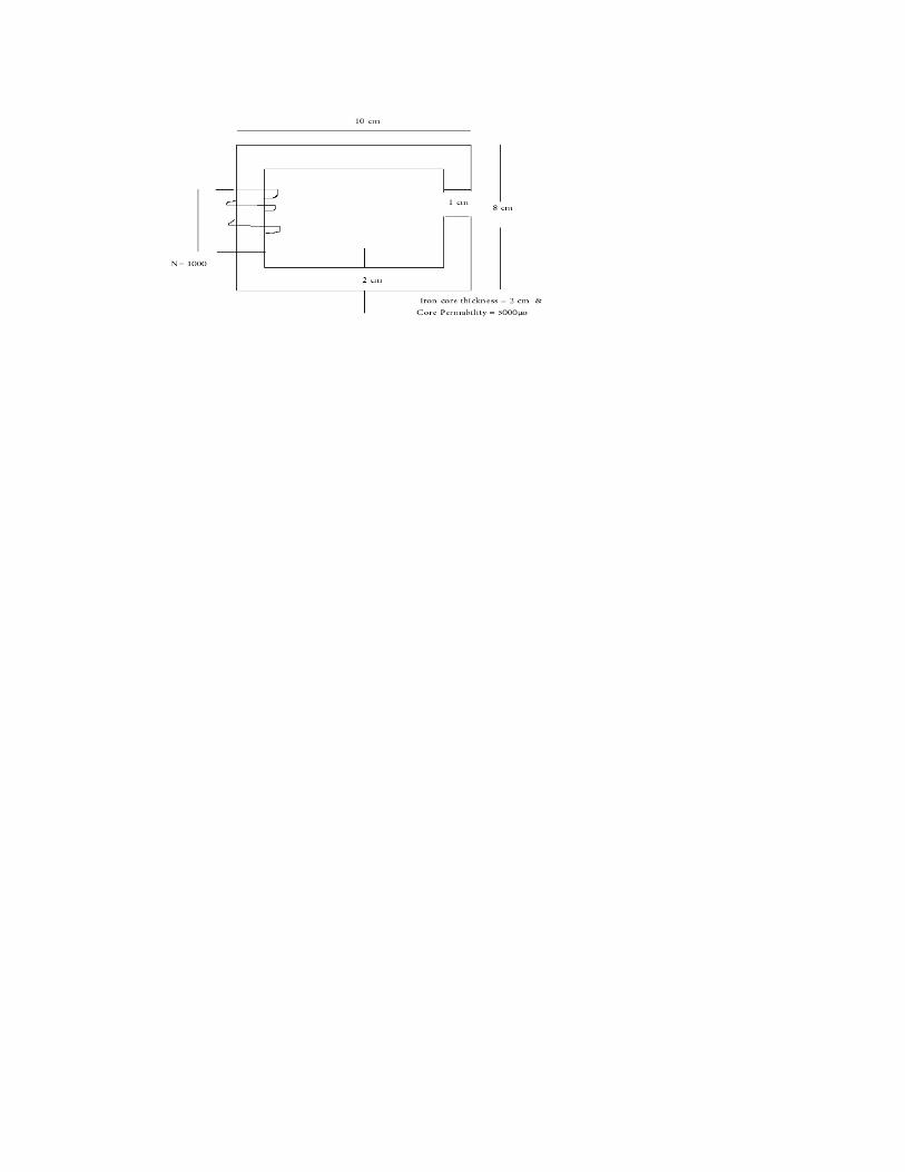
1. For the magnetic circuit as shown below, Calculate the self and mutual inductance Between the
two coils. Assume core permeability=1600 (16) (T-1 PG-33)MAY/JUNE 14
2. Explain the methods of energy conversion via Electric Field, with examples of Electrical Machines.
(16)---(T1 –P166) APRIL/MAY 15
3. Explain Hysteresis and Eddy current losses in Electrical machines along with the causes.
[T1-P36]
(i)Also give the methods in construction to minimize the above losses.(8)
(T-1 PG: 37) MAY /JUNE 16 , APRIL/MAY 15, NOV/DEC 13,APRIL/MAY 2011
(ii)List the properties of magnetic material suitable for fabrication Permanent Magnet and
Electromagnet. (8)---(T-1 PG-27) MAY /JUNE 16 APRIL/MAY 15
4. (i)Describe the AC operation of magnetic circuits. (8)---(T-1 PG-34) MAY/JUNE 14
(ii)Describe the principle of a typical magnetic circuit with explain. Also show that the core
reluctance may be neglected in practice. (8)---(T-1 PG-11) MAY/JUNE 14

5. The magnetic circuit :Ac=4*4cm2 Ig=0.06cm,Ic=40cmandN=600 turns. Assume the value of
μr=6000 for iron.Measure the exciting current for Bc=1.2T and the corresponding flux and flux
linkages. (16)(T-1 PG-18)MAY/JUNE 14
6. A single phase 50Hz,100 KVA transformer for 12000/240V ratio has a maximum flux density of
1.2Wb/m2and an effective core section of 300cm
2 the magnetizing current is 0.2A.Identify the
inductance of each wire on open circuit(16) MAY/JUNE 12
7. (i)Derive the expression for self and mutual inductance of the coil.(8)(T-1 PG-30)
(ii) Two coils A and B are wound on same iron core. There are 600 turns on A and 3600 turns on B.
The current of 4A through coil. A produces a flux of 500* 10-6
Wb in the core. If this current is
reversed in 0.02sec.Identify the average emf induced in coils A and B.(8)
8. (i)Explain the losses in magnetic materials(8)---(T-1 PG-36)
(ii)The field winding of the electromagnets is wound with 800turns and has a resistance of 40Ω
when exciting voltage is 230V, magnetic flux around the coil is 0.004.Calculate self-inductance and
energy in magnetic field.(8)
9. (i)Give the expression for energy density in the magnetic field.(4) (T-1 PG 35)
(ii)Describe Statically Induced EMF and Dynamically Induced EMF MAY/JUNE 12
(iii)The total core loss of a specimen of silicon steel is found to be 1500Watt 50Hz. Keeping the
flux density constant the loss becomes 3000W when the frequency is raised to 75Hz.Calculate
separately the hysteresis and eddy current loss at each of their frequencies.
(8)---(T-1 PG-38-39) APRIL/MAY 2011
10. Compare the similarities and dissimilarities between electric and magnetic circuits.(16)
NOV/DEC 2011 APRIL/MAY 2011
11. (i)Define Inductance of a coil.
(ii) Define permeability of a magnetic material and the factors on which it depends.
(iii) Explain the operation of AC magnetic cirvuit when AC current is applied to the coil wound on
iron core .Draw the B-H curve and obtain an expression for Hysteresis loss.
NOV/DEC 2009
12. A ring composed of three sections .The cross section is 0.001m2 for each section .the mean arc
length are La = 0.3m, Lb = 0.2m, Lc = 0.3m, an air gap length of 0.1 mm is cut in the ring ,µr for the
sections a,b, and c are 5000,1000 and 10000 respectively .Flux in the air gap is 7.5 x 10⁻⁴ Wb.Find (i)
mmf (ii)Exciting current if the coil has 100 turns (iii) Reluctance of the sections NOV/DEC 2011
13. For the magnetic circuit shown in fig determine the current requires to establish a flux density of
0.5 T in the air gap. NOV/DEC 2010
UNIT–II: TRANSFORMERS
PART:A
1. Define all day efficiency of a transformer? MAY/JUNE 16 It is computed on the basis of energy consumed during a certain period, usually a day of 24 hrs.
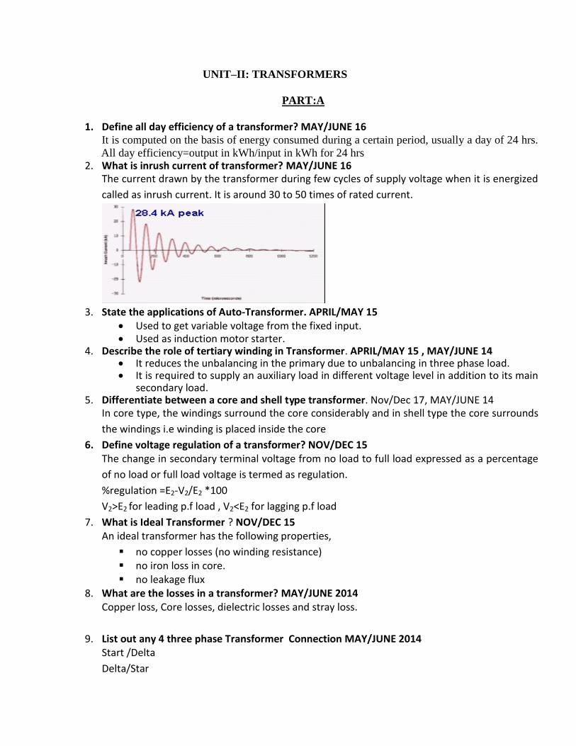
All day efficiency=output in kWh/input in kWh for 24 hrs 2. What is inrush current of transformer? MAY/JUNE 16
The current drawn by the transformer during few cycles of supply voltage when it is energized
called as inrush current. It is around 30 to 50 times of rated current.
3. State the applications of Auto-Transformer. APRIL/MAY 15
Used to get variable voltage from the fixed input. Used as induction motor starter.
4. Describe the role of tertiary winding in Transformer. APRIL/MAY 15 , MAY/JUNE 14 It reduces the unbalancing in the primary due to unbalancing in three phase load. It is required to supply an auxiliary load in different voltage level in addition to its main
secondary load. 5. Differentiate between a core and shell type transformer. Nov/Dec 17, MAY/JUNE 14
In core type, the windings surround the core considerably and in shell type the core surrounds
the windings i.e winding is placed inside the core
6. Define voltage regulation of a transformer? NOV/DEC 15 The change in secondary terminal voltage from no load to full load expressed as a percentage
of no load or full load voltage is termed as regulation.
%regulation =E2-V2/E2 *100
V2>E2 for leading p.f load , V2<E2 for lagging p.f load
7. What is Ideal Transformer ? NOV/DEC 15 An ideal transformer has the following properties,
no copper losses (no winding resistance) no iron loss in core. no leakage flux
8. What are the losses in a transformer? MAY/JUNE 2014 Copper loss, Core losses, dielectric losses and stray loss.
9. List out any 4 three phase Transformer Connection MAY/JUNE 2014 Start /Delta
Delta/Star

Scott Connection
Star /Star
10. What happens if DC supply is applied to the transformer? MAY/JUNE 2012 DC supply ( constant current) with frequency = 0, hence there won’t be any induced emf which left
the resistance alone to oppose the primary current. Thus its value is huge which in turn causes burning
out of the winding.
11. Explain why all day efficiency is lower than commercial efficiency? MAY/JUNE 2012 The load on the transformer varies with time and thus the energy losses.
12. Why is transformer rated in KVA? Justify. NOV/DEC 11 . Copper loss of a transformer depends on current & iron loss on voltage. Hence total losses
depend on Volt-Ampere and not on PF. That is why the rating of transformers is in kVA and not
in kW.
13. Compare two winding Transformer & Auto-Transfomer. NOV/DEC 11
S.No Transformer Auto-Transfomer
1 Has two windings One winding
2 Fixed output voltage Variable voltage
3 There is an Electrical isolation between windings No isolation
14. Which equivalent circuit parameters can be determined by the OC test of Transformer.APRIL/MAY 11 Core Losses Parameters [Ro, Xo, Xm, Io and Wo]
15. The emf per turn for a single-phase 2200/220V, 50Hz transformer is 11V. The number of primary and secondary turns. APRIL/MAY 11 Et=E1/N1 or E2/N2
N1=200; N2=20; [Et=11; E1=2200; E2=220]
16. Show the condition for parallel operation of a transformer? NOV/DEC 9 Same voltage ratio of transformer.
Same percentage impedance.
Same polarity.
Same phase sequence
17. Define principle of transformer? APRIL/MAY 2010 A transformer is a static device which transfers power from one circuit to another circuit
without changing the frequency by mutual induction principle.
18. Draw the phasor diagram of transformer on No-Load?NOV/DEC 9 [BLT – P1126]
19. What is the purpose of laminating the core in a transformer? In order to minimise eddy current loss.
20. Give the emf equation of a transformer and define each term? Emf induced in primary coil E1= 4.44fФmN1 volt

Emf induced in secondary Coil E2 =4.44 fФmN2.
f--freq of AC input
Фm-maximum value of flux in the core
N1, N2-Number of primary & secondary turns.
21. Does transformer draw any current when secondary is open? Why? Yes, it (primary) will draw the current from the main supply in order to magnetize the core and
to supply for iron and copper losses on no load. There will not be any current in the secondary
since secondary is open.
22. What determines the thickness of the lamination or stampings? Frequency
Iron loss
23. What are the applications of step-up & step-down transformer? Step-up transformers are used in generating stations. Normally the generated voltage will be
either 11kV. This voltage (11kV) is stepped up to 110kV or 220kV or 400kV and transmitted
through transmission lines (simply called as sending end voltage).
Step-down transformers are used in receiving stations. The voltage are stepped down to11kV
or 22kV are stepped down to 3phase 400V by means of a distribution transformerand made
available at consumer premises. The transformers used at generating stationsare called power
transformers.
24. How transformers are classified according to their construction? 1. Core type 2.shell type. In core type, the winding (primary and secondary)
surround the core and in shell type, the core surround the winding.
25. Explain on the material used for core construction? The core is constructed by sheet steel laminations assembled to provide a continuous magnetic
path with minimum of air gap included. The steel used is of high silicon content sometimes
heat treated to produce a high permeability and a low hysteresis loss at the usual operating flux
densities. The eddy current loss is minimized by laminating the core, the laminations being used
from each other by light coat of core plate vanish or by oxide layer on the surface. The thickness
of lamination varies from 0.35mm for a frequency of 50Hz and 0.5mm for a frequency of 25Hz.
26. How does change in frequency affect the operation of a given transformer? With a change in frequency, iron and copper loss, regulation, efficiency & heating varies so the
operation of transformer is highly affected.
27. What is the angle by which no-load current will lag the ideal applied voltage? In an ideal transformer, there are no copper & core loss i.e. loss free core. The no load current is
only magnetizing current therefore the no load current lags behind by angle 90. However the
winding possess resistance and leakage reactance and therefore the no
load current lags the applied voltage slightly less than 90 .
28. List the advantages of stepped core arrangement in a transformer? To reduce the space effectively
To obtain reduced length of mean turn of the winding
To reduce I R loss.
29. Why are breathers used in transformers? Breathers are used to entrap the atmospheric moisture and thereby not allowing it to pass on to
the transformer oil. Also to permit the oil inside the tank to expand and contract as its
temperature increases and decreases.

30. What is the function of transformer oil in a transformer? It provides good insulation
Cooling
31. Can the voltage regulation goes –ive? If so under what condition? Yes, if the load has leading PF.
32. Distinguish power transformers & distribution transformers? Power transformers have very high rating in the order of MVA. They are used in generating and
receiving stations. Sophisticated controls are required. Voltage ranges will be very high.
Distribution transformers are used in receiving side. Voltage levels will be medium. Power
ranging will be small in order of kVA. Complicated controls are not needed.
33. Name the factors on which hysteresis loss depends? 1. Frequency 2. Volume of the core 3. Maximum flux density
34. Why the open circuit test on a transformer is conducted at rated voltage? The open circuit on a transformer is conducted at a rated voltage because core loss depends
upon the voltage. This open circuit test gives only core loss or iron loss of the transformer.
35. What is the purpose of providing Taps in transformer and where these are provided? In order to get different voltage levels at secondary, tapings are provided,
36. What are the necessary tests to determine the equivalent circuit of the transformer?
1. Open circuit test
2. Short circuit test
37. Define efficiency of the transformer? Transformer efficiency ή= (output power/input power) x 100
38. Full load copper loss in a transformer is 1600W. What will be the loss at half load? If n is the ratio of actual load to full load then
copper loss = n2 (F.L copper loss) -Pc = (0.5)
2 – 1600=400W
PART:B
1. Draw a circuit and explain how to obtain equivalent circuit by conducting O.C & S.C test in a
single phase Transformer. [T1-P81-82] MAY/JUNE 16,12 APRIL/MAY 10
2. Explain the various three phase transformer connection and parallel operation of three phase
transformer. MAY/JUNE 16[T1-P132
3. What is meant by inrush current in Transformer? Specify the nature of Inrush currents and its
problem during Transformer charging.[T1-102] APRIL/MAY 15
4. A 500KVATransformer has a core loss of 2200 watts and a full load copper loss of 7500
watts.If the power factor of the load is 0.90 lagging, Evaluate the full load efficiency and the
KVA load at which maximum efficiency occurs. APRIL/MAY 15
5. Specify the conditions for parallel operation of Transformer .Also explain the effect of load
sharing due to impedance variation between transformer during parallel operation.
APRIL/MAY 15 , NOV/DEC 13[ T-1 P-126]
6. A100 KVA,3300V/240V,50HZ single phase transformer has 990 turns on the primary. Identify
the number of turns on secondary and the approximate value of primary and secondary full load
currents. APRIL/MAY 15
7. (i)Explain the principle of operation of a transformer. Derive its emf equation.(8)[T-1 P-53 ]
MAY/JUNE 14

(ii)A single phase transformer has 180turns respectively in it secondary and primary windings.
The respective resistances are 0.233 and 0.067.Calculate the equivalent resistance of a)the
primary in terms of the secondary winding b)the secondary interms of the primary winding
c)the total resistance of the transformer interms of the primary(8) MAY/JUNE 14
8. Describe the phasor diagram of transformer when it is operating under load and explain.(8)
MAY/JUNE 14 [BLT P-1129] 9. The parameters of approximate equivalent circuit of a 4KVA,200/400V,50Hz single phase
transformer are R’p=0.15Ω;X’p=0.37Ω;Ro=600Ω;Xm=300Ω when a rated voltage of 200V ia applied to the primary, a current of 10A at lagging power factor of 0.8 flows in the secondary winding. Identify
(i)The current in the primary,Ip (ii)The terminal voltage at the secondary side.(8)
MAY/JUNE 14
10. Explain the construction and working of core type and shell type transformers with neat
sketches.(16) [BLT- P-1118] MAY/JUNE 13 11. Explain the construction and principle of a working transformer . [T-1 P-61](8) NOV/DEC13
12. Develop the equivalent circuit of a single phase transformer Referred to primary and
secondary.(16) [T1- P-60] NOV/DEC13 APRIL/MAY 10
13. Obtain the equivalent circuit of a 200/400V 50Hz single phase transformer from the following
test data.
O.C.test:200V,0.7W,70W –on L.VSide
S.C.test:15V,10A,85W on H.Vside
Calculate the secondary voltage when delivering 5kW at 0.8p.f.lagging.Theprimary
voltagebeing200V. (16)
14. (i)Derive an expression for maximum efficiency of a transformer.(8)--- (T-1 P-79)
15. Derive an expression for the emf of an ideal transformer. MAY/JUNE 12
16. Calculate the efficiency at half,full load of a 100 KVA transformer for PF of unity and 0.8
.The copper loss is 1000 W at full load and iron loss is 1000 W. MAY/JUNE 12
17. Explain the causes of voltage drop in a power transformer on load and develop the equivalent
circuit for a single phase transformer. NOV/DEC 11
18. A 3 phase step down transformer is connected to 6.6 KV mains and takes 10 Amps.Calculate
the secondary line voltages and line current for the (i) ∆/∆ (ii) Ỵ/Ỵ (iii) ∆/ Ỵ (iv) Ỵ/∆
connection.The ratio of turns per phase is 12 and neglect no load losses.
MAY/JUNE 12 19. Derive an expression for saving copper when an auto transformer is used.
MAY/JUNE 12, APRIL/MAY 10 20. Obtain the equivalent circuit of a 2000/200V 50Hz single phase transformer referred to HV
and LV sides respectively from the following test data.
O.C.test:200V,4,120W –on L.VSide
S.C.test:60V,10A,300W on H.Vside APRIL/MAY 11
21. A three transformer bank consisting of three single phase transformers is used to step down the
voltages of a 3phase ,6600V transmission .If the primary line current is 10 A ,Calculate the
secondary line voltages, line current and output KVA for the following connections:
(1) ∆/ Ỵ (2) Ỵ/∆ ,Turns ratio is 12 .Neglect losses. APRIL/MAY 11
22. A 20 kVA ,2500/500 V,single –phase tensformer has the following parameters: HV WINDING: r1= 8 ohm and x1= 17 ohm LV WINDING : r2= 0.3 ohm and x2=0.7 ohm
Find the voltage regulation and the secondary terminal at full llad for a pf of 0.8 lagging and 0.8 leading.the primary voltages is held constant at 2500V .
APRIL/MAY 11 23. Define the voltage regulation of two winding transformer and explain its significance.
NOV/DEC 10 24. A 100 kVA ,6600 V / 330V,50 Hz single phase transformer took 10 A and 436W at 100V in
a short in a short circuit test,the figure reffering to the high voltage side.Calculate the voltage to be applied to the high voltage side on full load at power factor 0.8 lagging when the secondary terminal voltage is 300 V. NOV/DEC 10
25. Explain various types of three phase transformer connections. APRIL/MAY 10 26. A transformer has its maximum efficiency of 0.98 at 15kVA at unity power factor. During
the day it is loaded as follows: 12 hour 2kW at power factor 0.6 6 hour 12kW at power factor 0.8 4 hour 18kW at power factor 0.9 2 hour No load NOV/DEC 10
27. The voltage per turn of a single phase transformeris1.1volt,when the primary winding is
connected to a 220volt,50Hz AC supply the secondary voltage is found to be 550volt. Identify
the primary and secondary turns and core area if maximum flux density is 1.1Tesla.(16)
28. Describe the principle of operation of a transformer. Draw the vector diagram to represent a
load at UPF,lagging and leading power factor.(16)
T-1 P-53 APRIL/MAY 10
29. Two 100KW transformer each has a maximum efficiency of 98% but in one the maximum
efficiency occurs at full-load while in the other, it occurs at half-load. Each transformer is on
full-load for 4 hours, on half-load for 6 hours and one-tenth load for 14 hours per
day.Dertermine the all-day efficiency of each transformer. NOV/DEC 09
30. Derive an expression for Maximum efficiency of a transformer.[BLT-P1169]
NOV/DEC 09 31. Two 100kW ,single phase transformer are connected in parallel both on the primary and
secondary .One transformer has an ohmic drop 0.5% at full load and an inductive drop of 8%
at full load current.the other has an ohmic drop of 0.75% and inductive drop 0.75% and
inductive drop of 2% Show how they will share a load of 180KW at 0.9 power .
NOV/DEC 09 32. Explain Sumpner’s test.[T1-P86]
33. A 500KVAtransformer has 95% efficiency at full load and also at 60% of full load of that
UPF. a)Separate out the transformer losses.b)Measure the transformer efficiency at 75% full
load, UPF.(8)

UNIT–III
ELECTROMECHANICAL ENERGY CONVERSION
AND CONCEPTS IN ROTATING MACHINES
PART:A
1. What is meant by winding Indutance. MAY/JUNE 2016
If a changing flux is linked with a coil of a conductor there would be an emf induced in
it. The property of the coil of inducing emf due to the changing flux linked with it is known as
inductance of the coil. Due to this property all electrical coil can be referred as inductor. In
other way, an inductor can be defined as an energy storage device which stores energy in form
of magnetic field.
2. Write the equation which relates rotor speed in electrical and mechanical radian/second. April/May 2015 ωe= ωm*(p/2)
ωe= rotor speed in electrical radians per sec
ωm=speed in mechanical radians per sec
p=no of poles
3. Write the equation which relates electrical and mechanical angles of P pole machine. Nov/Dec 2010 Өe = Өm *P/2
Өe – Electrical angle
Өm – Mechanical angle
4. Explain the concept of electrical degrees nov/dec 2010 It is calculated according to the no of poles of stator. Each pole contributes 1800 of
electrical angle. If stator has 4 poles then the electrical angle will be 7200
5. Give Examples of Multiple Excitation System. MAY/JUNE 2013 Single excited system-reluctance motor, single phase transformer, relay coil
Multiply excited system-alternator, electro mechanical transducer
6. Formulate the expression for torque in round rotor machine.MAY/JUNE 2013 T= ( -π/2) * (p/2)2 φr F2 Sinδ
T – Torque
P – No of poles
φr - Resultant flux per pole
F2 – Rotor spatial mmf
7. List the basic requirements of the excitation systems? MAY/JUNE 2013 The core, coil and supply are required to make an excitation system
8. Block diagram of Electromechanical Energy conversion. NOV/DEC 2011

9. State the principle of electromechanical energy conversion? Nov/Dec 17,April/May 2011
The mechanical energy is converted in to electrical energy which takes place through either by
magnetic field or electric field
10. What is the significance of co energy? May/June 16,May/June 2012 & 2013 When electrical energy is fed to coil not the whole energy is stored as magnetic energy the co
energy gives a measure of other energy conversion which takes place in coil then magnetic
energy storage [ie energy which is converted to other form]
11. What does speed voltage mean? It is that voltage generated in that coil, when there exists a relative motion between coil and
magnetic field
12. Why do all practical energy conversion devices make use of the magnetic field as a coupling medium rather than electric field? May/June 2014 When compared to electric field, energy can be easily stored and retrieved form a magnetic
system with reduced losses comparatively. Hence most all practical energy conversion devices
make use of magnetic medium as coupling
13. State necessary condition for production of steady torque by the interaction of stator and rotor field in electric machines?
The stator and rotor fields should not have any relative velocity or speed between each other
Air gap between stator and rotor should be minimum
Reluctance of iron path should be negligible
Mutual flux linkages should exist between stator and rotor windings
14. Write the application of single and doubly fed magnetic systems? Singly excited systems are employed for motion through a limited distance or rotation through
a prescribed angle Whereas multiply excited systems are used where continues energy
conversion take place and in ease of transducer where one coil when energized the care of
setting up of flux and the other coil when energized produces a proportional signal either
electrical or mechanical
15. Define pole pitch Pole pitch is that centre to centre distance between any two consecutive poles in a rotating
machine, measured in slots per poles
16. Define short charding angle Chording angle is that angle by which the coil span is short of full pitched in electrical degrees
17. Why energy stored in a magnetic material always occur in air gap In iron core or steel core the saturation and aging effects form hindrance to storage Built in air
gap as reluctance as well permeability is constant, the energy storage takes place linearly
without any complexity Hence energy is stored in air gap in a magnetic medium
18. Relate co energy density and magnetic flux density? Co energy density=wf=∫λ (I, x) di
wf=1/2BH
19. . Short advantages of short pitched coil? Harmonics are reduced in induced voltage
Saving of copper
End connections are shorter
20. What is the significance of winding factor? Winding factor gives the net reduction in emf induced due to short pitched coil wounding
distributed type
Winding factor kw=kp*kd
kp= pitch factor
kd= distribution factor
kp= cos(α/2)
kd= sin(mγ/2)/msin(γ/2)
21. What is the necessity to determine the energy density in the design of rotating machines? Energy density wf=B
2/2μ
22. Derive the relation between co energy and the phase angle between the rotor and stator fluxes of the rotating machines? F1, f2 are the rotor and stator flux peak values respectively
Fr2=f12+f22+2f1f2cosα
Co energy= f12+f22+2f1f2cosα
23. Write the energy balance equation for motor? Mechanical energy o/p=electrical energy i/p-increase in field energy
Ff dx=idλ-dWf
24. What is magnetic circuit? The closed path followed by magnetic flux is called magnetic circuit
25. Define magnetic flux? The magnetic lines of force produced by a magnet is called magnetic flux it is denoted as
Ф and its unit is Weber
26. Define magnetic flux density? NOV/DEC 17 It is the flux per unit area at right angles to the flux it is denoted by B and unit is Weber/m2
27. Define magneto motive force? MMF is the cause for producing flux in a magnetic circuit. the amount of flux setup in the core
decent upon current(I)and number of turns(N).the product of NI is called MMFand it determine
the amount of flux setup in the magnetic circuit MMF=NI ampere turns (AT)
28. Give the materials used in machine manufacturing? There are three main materials used in m/c manufacturing they are steel to conduct magnetic
flux copper to conduct electric current insulation.
29. What are factors on which hysteresis loss? It depends on magnetic flux density, frequency & volume of the material.
30. What is core loss? What is its significance in electric machines? When a magnetic material undergoes cyclic magnetization, two kinds of power losses occur on
it. Hysteresis and eddy current losses are called as core loss. It is important in determining
heating, temperature rise, rating & efficiency of transformers, machines & other A.C run
magnetic devices.
PART-B
1. Explain the concept of singly excited machine and derive the expression for electromagnetic
torque [or] Obtain the expression for energy in a attracted armature relay magnetic system
May/June 2016 (T-1 P- 158)
2. Derive an expression for co energy in multiply excited magnetic field systems May/June 2016
& 2015 ( T-1 P-178)
3. Derive the torque equation of a round rotor machine clearly stating all the assumption made
give the relation between field energy and the mechanical force developed in the field
May/June 2015 ( T1 - P-241)
4. Explain the production of rotating magnetic field. What are the speed and direction of rotation
of the field? Is the speed uniform? May/June 2014& Nov/Dec 2013 [T1-P233]
5. What is meant by current sheet concept? Explain briefly. What is the phase difference between
a sinusoidally distributed current sheet and its accompanying mmf wave? May June 2014 [T1-
P231]
6. A 4 pole lap wound DC machine has 728 armature conductors. Its field winding is excited from
a DC source to create an air gap flux of 32 mwb/pole. The machine is from a prime mover at
1600 RPM. It supplies a current of 100A to an electric load
a. Calculate the electromagnetic power developed
b. What is the mechanical power that is fed from the prime mover to the generator
c. What is the torque provided by the prime mover
7. Explain the mmf pattern of distributed winding of a machine. Nov/Dec 2013 [T1-P228]
UNIT-4
PART-A
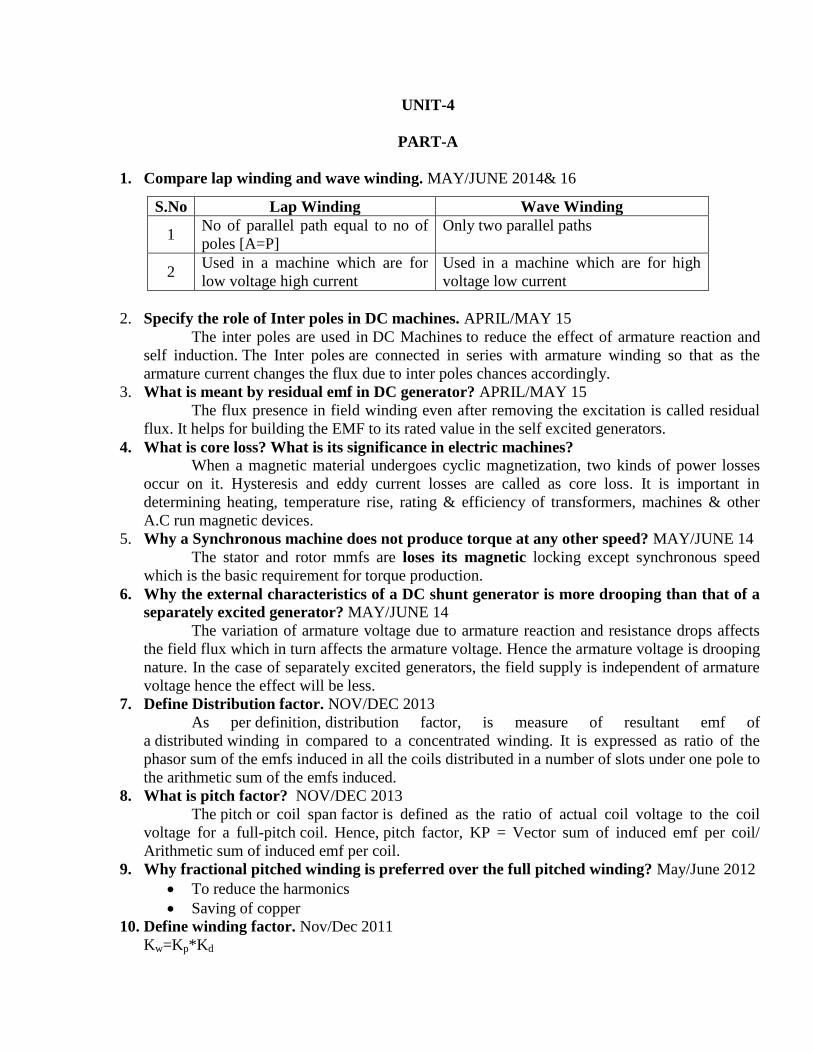
1. Compare lap winding and wave winding. MAY/JUNE 2014& 16
S.No Lap Winding Wave Winding
1 No of parallel path equal to no of
poles [A=P]
Only two parallel paths
2 Used in a machine which are for
low voltage high current
Used in a machine which are for high
voltage low current
2. Specify the role of Inter poles in DC machines. APRIL/MAY 15
The inter poles are used in DC Machines to reduce the effect of armature reaction and
self induction. The Inter poles are connected in series with armature winding so that as the
armature current changes the flux due to inter poles chances accordingly.
3. What is meant by residual emf in DC generator? APRIL/MAY 15
The flux presence in field winding even after removing the excitation is called residual
flux. It helps for building the EMF to its rated value in the self excited generators.
4. What is core loss? What is its significance in electric machines?
When a magnetic material undergoes cyclic magnetization, two kinds of power losses
occur on it. Hysteresis and eddy current losses are called as core loss. It is important in
determining heating, temperature rise, rating & efficiency of transformers, machines & other
A.C run magnetic devices.
5. Why a Synchronous machine does not produce torque at any other speed? MAY/JUNE 14
The stator and rotor mmfs are loses its magnetic locking except synchronous speed
which is the basic requirement for torque production.
6. Why the external characteristics of a DC shunt generator is more drooping than that of a
separately excited generator? MAY/JUNE 14
The variation of armature voltage due to armature reaction and resistance drops affects
the field flux which in turn affects the armature voltage. Hence the armature voltage is drooping
nature. In the case of separately excited generators, the field supply is independent of armature
voltage hence the effect will be less.
7. Define Distribution factor. NOV/DEC 2013
As per definition, distribution factor, is measure of resultant emf of
a distributed winding in compared to a concentrated winding. It is expressed as ratio of the
phasor sum of the emfs induced in all the coils distributed in a number of slots under one pole to
the arithmetic sum of the emfs induced.
8. What is pitch factor? NOV/DEC 2013
The pitch or coil span factor is defined as the ratio of actual coil voltage to the coil
voltage for a full-pitch coil. Hence, pitch factor, KP = Vector sum of induced emf per coil/
Arithmetic sum of induced emf per coil.
9. Why fractional pitched winding is preferred over the full pitched winding? May/June 2012
To reduce the harmonics
Saving of copper
10. Define winding factor. Nov/Dec 2011
Kw=Kp*Kd

Kp- Pitch factor
Kd- Distribution factor
11. Draw the various characteristics of DC shunt generator. MAY/JUNE 16
12. Define Commutation. MAY/JUNE 2012
The commutation in DC machine or more specifically commutation in DC generator is the
process in which generated alternating current in the armature winding of a dc machine is
converted into direct current after going through the commutator and the stationary brushes
13. Write down the emf equation for d.c.generator? E= (ФNZ/60) (P/A) Volt
p- no of poles
Z-Total no of conductor
Ф-flux per pole
N-speed in rpm.
14. Why the armature core in d.c machines is constructed with laminated steel sheets instead
of solid steel sheets? Lamination highly reduces the eddy current loss and steel sheets provide low reluctance path to
magnetic field.
15. Why commutator is employed in d.c.machines? Conduct electricity between rotating armature and fixed brushes, convert alternating emf into
unidirectional emf (mechanical rectifier).
16. Distinguish between shunt and series field coil construction?
Shunt field coils are wound with wires of small section and have more no of turns. Series field
coils are wound with wires of larger cross section and have less no of turns.
17. How does D.C. motor differ from D.C. generator in construction? Generators are normally placed in closed room and accessed by skilled operators only.
Therefore on ventilation point of view they may be constructed with large opening in the frame.
Motors have to be installed right in the place of use which may have dust, dampness,
inflammable gases, chemicals….etc. to protect the motors against these elements, the motor
frames are made either partially closed or totally closed or flame proof.
18. What is the function of no-voltage release coil in D.C. motor starter? As long as the supply voltage is on healthy condition the current through the NVR coil produce
enough magnetic force of attraction and retain the starter handle in ON position against spring
force. When the supply voltage fails or becomes lower than a prescribed value then
electromagnet may not have enough force to retain so handle will come back to OFF position
due to spring force automatically.
19. Enumerate the factors on which speed of a d.c.motor depends? N= (V-IaRa)/Ф

so speed depends on air gap flux, resistance of armature, voltage applied to armature.
20. Under What circumstances a dc shunt generator does fails to generate? Absence of residual flux, initial flux setup by field may be opposite in direction to residual
flux, shunt field circuit resistance may be higher than its critical field resistance; load circuit
resistance may be less than its critical load resistance.
21. Define critical field resistance of dc shunt generator? Critical field resistance is defined as the resistance of the field circuit which will cause the shunt
generator just to build up its emf at a specified field.
22. Why is the emf not zero when the field current is reduced to zero in dc generator? Even after the field current is reduced to zero, the machine is left out with some flux as residue
so emf is available due to residual flux.
23. On what occasion dc generator may not have residual flux? The generator may be put for its operation after its construction, in previous operation; the
generator would have been fully demagnetized.
24. What are the conditions to be fulfilled by for a dc shunt generator to build back emf? The generator should have residual flux, the field winding should be connected in such a
manner that the flux setup by field in same direction as residual flux, the field resistance should
be less than critical field resistance, load circuit resistance should be above critical resistance.
25. Define armature reaction in dc machines? May/June 2013
The interaction between the main flux and armature flux cause disturbance called as armature
reaction.
26. What are two unwanted effects of armature reactions? Cross magnetizing effect & demagnetizing effect.
27. What is the function of carbon brush used in dc generators? The function of the carbon brush is to collect current from commutator and supply to external
load circuit and to load.
28. Why an induction motor is called as rotating transformer? The rotor receives same electrical power in exactly the same way as the secondary of a two
winding transformer receiving its power from primary. That is why induction motor is called as
rotating transformer.
29. Why an induction motor never runs at its synchronous speed? If it runs at synchronous speed then there would be no relative speed between the two, hence no
rotor emf, so no rotor current, then no rotor torque to maintain rotation.
30. What are slip rings?
The slip rings are made of copper alloys and are fixed around the shaft insulating it. Through
these slip rings and brushes rotor winding can be connected to external circuit.
31. Why fractional pitched winding is preferred over full pitched winding? MAY/JUNE 2013
Waveform of the emf can be approximately made to a sine wave and distorting harmonics can
be reduced or totally eliminated. Conductor material, copper, is saved in the back and front end
connections due to less coil-span. Fractional slot winding with fractional number of slots/phase
can be used which in turn reduces the tooth ripples. Mechanical strength of the coil is increased.
32. Name any 2 non-loading method of testing dc machines?
Swinburne’s test
Hopkinson test
33. Define armature reaction in dc machines?
The interaction between the main flux and armature flux cause disturbance called as armature
reaction.
34. What are two unwanted effects of armature reactions? Cross magnetizing effect & demagnetizing effect.
35. What is the function of carbon brush used in dc generators? The function of the carbon brush is to collect current from commutator and supply to external
load circuit and to load.
PART-B
1. Derive the emf equation of an DC generator (8) May/June 2016, April/may2015,
NOV/DEC2011 (T-1 P-317)
2. Explain armature reaction of DC machines.(8) May/June 2016 (T-1 P-325)
3. Draw and explain the load characteristics of Differentially and Cumulatively compound DC
generator.[8] April/may2015 (T-1 P-348)
4. Constructional features and operation of dc generator. [10] Nov/Dec2013 ( T-1 P-315)
5. Explain various Characteristics of DC Generator. [6] Nov/Dec2013, MAY/JUNE
2012,NOV/DEC 2010 (T-1 P-348)
6. Explain the working principles of different types of DC generators [16] May/June 2013 (BLT P
-881 &911)
7. Explain commutation process in D.C. motor.[8] NOV/DEC 2013
8. Derive the torque equation of DC motor.[8] NOV/DEC 2013
9. A 4 pole DC motor is lap wound with 400 conductors. The pole shoe is 20cm long and the
average flux density over the one pole pitch is 0.4T, the armature diameter being 30cm. find the
torque and gross mechanical power developed when the motor is drawing 25A and running at
1500 RPM. [8] May/June 2016
10. A 4 pole DC shunt generator with lap connected armature supplies 5 KW at 230V. The
armature and field copper losses are 360W and 200W respectively. Calculate the armature
current and generated EMF? [10] May/June 2016
11. In a 400V DC compound generator, the resistance of the armature, series and shunt windings
are 0.05Ω and 100 Ω respectively. The machine supplies power to 20 nos. resistive heaters,
each rated 500W 400V. Calculate the induced emf and armature currents when the generator is
connected in 1. Short shunt, 2. Long shunt. Allow brush contact drop of 2V per brush. [10]
May/June 2016

UNIT-5
PART- A
1. Draw the speed torque characteristics of DC series motor MAY/JUNE 16
2. What is meant by plugging? MAY/JUNE 16
Type of braking is Plugging type braking. In this method the terminals of supply are reversed,
as a result the generator torque also reverses which resists the normal rotation of the motor and
as a result the speed decreases. During plugging external resistance is also introduced into the
circuit to limit the flowing current. The main disadvantage of this method is that here power is
wasted.
3. Specify the techniques used to control the speed of DC shunt motor for below and above
the rated speed? APRIL/MAY 15
Flux control method
Voltage control method
4. Why DC motor is suitable for traction applications? APRIL/MAY 15
Because of High starting current and high starting torque
5. What is armature reaction? NOV/DEC 13
Armature reaction in a DC machine. In a DC machine, the main field is produced by field coils.
In both the generating and motoring modes, the armature carries current and a magnetic field is
established, which is called the armature flux. The effect ofarmature flux on the main field is
called the armature reaction.
6. How to control speed by armature control method in DC shunt motor? NOV/DEC 13.
In the armature control method, the speed of the DC motor is directly proportional to the back
emf (Eb) and Eb = V- IaRa. When supply voltage (V) and armature resistance Ra are kept
constant, the Speed is directly proportional to armature current (Ia). If we add resistance in
series with the armature, the armature current (Ia) decreases and hence speed decreases. This
armature control method is based on the fact that by varying the voltage across the required
voltage. The motor back EMF (Eb) and Speed of the motor can be changed. This method is
done by inserting the variable resistance (Rc) in series with the armature.
7. What are the applications of DC series motor? NOV/DEC 13
Its high starting torque makes it particularly suitable for a wide range of traction applications.
Industrial uses are hoists, cranes, trolly cars, conveyors, elevators, air compressors, vacuum
cleaners, sewing machines etc.
8. What is eddy current loss? When a magnetic core carries a time varying flux, voltages are induced in all possible path
enclosing flux. Resulting is the production of circulating flux in core. These circulating current
do no useful work are known as eddy current and have power loss known as eddy current loss.
9. How hysteresis and eddy current losses are minimized?

Hysteresis loss can be minimized by selecting materials for core such as silicon steel & steel
alloys with low hysteresis co-efficient and electrical resistivity. Eddy current losses are
minimized by laminating the core.
10. How will you find the direction of emf using Fleming’s right hand rule? The thumb, forefinger & middle finger of right hand are held so that these fingers are mutually
perpendicular to each other, then forefinger gives the direction of the lines of flux, thumb gives
the direction of the relative motion of conductor and middle finger gives the direction of the emf
induced.
11. How will you find the direction of force produced using Fleming’s left hand rule? The thumb, forefinger & middle finger of left hand are held so that these fingers are mutually
perpendicular to each other, then forefinger gives the direction of magnetic field, middle finger
gives the direction of the current and thumb gives the direction of the force experienced by the
conductor.
12. What is the purpose of yoke in d.c machine? Nov/Dec 17
It acts as a protecting cover for the whole machine and provides mechanical support for the
poles.
It carries magnetic flux produced by the poles
13. What are the types of armature winding?
Lap winding, A=P,
Wave winding, A=2.
14. How are armatures windings are classified based on placement of coil inside the armature
slots? Single and double layer winding.
15. Write down the emf equation for d.c.generator? E= (ФNZ/60)(P/A)V.
p-no of poles
Z-Total no of conductor
Ф-flux per pole
N-speed in rpm.
16. Why the armature core in d.c machines is constructed with laminated steel sheets instead
of solid steel sheets? Lamination highly reduces the eddy current loss and steel sheets provide low reluctance path to
magnetic field.
17. Why commutator is employed in d.c.machines?
Conduct electricity between rotating armature and fixed brushes, convert alternating emf into
unidirectional emf (mechanical rectifier).
18. Distinguish between shunt and series field coil construction? Shunt field coils are wound with wires of small section and have more no of turns. Series field
coils are wound with wires of larger cross section and have less no of turns.
19. How does d.c. motor differ from d.c. generator in construction? Generators are normally placed in closed room and accessed by skilled operators only.
Therefore on ventilation point of view they may be constructed with large opening in the frame.
Motors have to be installed right in the place of use which may have dust, dampness,
inflammable gases, chemical etc. to protect the motors against these elements the motor frames
are used partially closed or totally closed or flame proof.
20. How will you change the direction of rotation of d.c.motor? Either the field direction or direction of current through armature conductor is reversed.
21. What is back emf in d.c. motor? NOV/DEC 11 As the motor armature rotates, the system of conductor come across alternate north and South
Pole magnetic fields causing an emf induced in the conductors. The direction of the emf
induced in the conductor is in opposite to current. As this emf always opposes the flow of
current in motor operation it is called as back emf.
22. What is the function of no-voltage release coil in d.c. motor starter? As long as the supply voltage is on healthy condition the current through the NVR coil produce
enough magnetic force of attraction and retain the starter handle in ON position against spring
force. When the supply voltage fails or becomes lower than a prescribed value then
electromagnet may not have enough force to retain so handle will come back to OFF position
due to spring force automatically.
23. Enumerate the factors on which speed of a d.c.motor depends?
N= (V-IaRa)/Ф so speed depends on voltage applied to armature, flux per pole, resistance of
armature.
24. Under what circumstances does a dc shunt generator fails to generate? Absence of residual flux, initial flux setup by field may be opposite in direction to residual flux,
shunt field circuit resistance may be higher than its critical field resistance, load circuit
resistance may be less than its critical load resistance.
25. Define critical field resistance of dc shunt generator? Critical field resistance is defined as the resistance of the field circuit which will cause the shunt
generator just to build up its emf at a specified field.
26. Why is the emf not zero when the field current is reduced to zero in dc generator? Even after the field current is reduced to zero, the machine is left out with some flux as residue
so emf is available due to residual flux.
27. On what occasion dc generator may not have residual flux? The generator may be put for its operation after its construction, in previous operation, the
generator would have been fully demagnetized.
28. What are the conditions to be fulfilled by for a dc shunt generator to build back emf? The generator should have residual flux, the field winding should be connected in such a
manner that the flux setup by field in same direction as residual flux, the field resistance should
be less than critical field resistance, load circuit resistance should be above critical resistance.
29. Define armature reaction in dc machines? The interaction between the main flux and armature flux cause disturbance called as armature
reaction.
30. What are two unwanted effects of armature reactions? Cross magnetizing effect & demagnetizing effect.
31. What is the function of carbon brush used in dc generators? The function of the carbon brush is to collect current from commutator and supply to external
load circuit and to load.
32. What is the principle of generator? When the armature conductor cuts the magnetic flux emf is induced in the conductor.
33. What is the principle of motor? When a current carrying conductor is placed in a magnetic field it experiences a force tending to
move it.
PART-B
1. Explain the method used to obtain efficiency at full load by conducting Hopkinson’s Test. [16]
BLT-1099] May/June 2016
2. The no load test of a 44.76 KW, 220V, D.C shunt motor gave the following figures; input
current=13.25A, Field current=2.55A, resistance of the armature at 750C=0.032Ω, and brush
drop=2V. Estimate the full load current and efficiency [16] May/June 2016
3. Derive the torque equation of a DC motor from first principle. And explain the characteristics of
DC shunt motor (12) (T-1 P-358) May/June 2014
4. What are the merits and demerits of hopkinson’s test [4] [BLT-1101] May/June 2014
5. Explain how to obtain efficiency of DC motor by hopkinson’s test [10] [BLT-1099] May/June
2014
6. Discuss in detail about shunt armature speed control of DC shunt motor [8] May/June 2014
[BLT-1041]
7. A 500V DC shunt motor running at 700 RPM takes an armature current of 50A. Its effective
resistance is 0.4Ω. what resistance must be placed in series with armature to reduce the speed to
600RPM, the torque remaining constant? [8] May/June 2014
8. Explain the starting of DC motor using three point starter [8] [BLT-1074] Nov/Dec 2013
9. Describe how to obtain breaking in D.C. Shunt motor. [8] [BLT-1064] Nov/Dec 2013
10. Discuss in detail about field control method speed control of DC shunt motor and state its
applications [8] Nov/Dec 2013 [BLT-1032]
11. With schematic diagrams, explain the working principle of different types of DC generator
based on its excitation. [16] [BLT-890] May/June 2013.
12. Explain different methods of speed control of DC shunt motor with neat circuit diagrams [16]
[BLT-1041] May/June 2013