jenka system 866 0
TRANSCRIPT
JENKA System
3/2008
3
www.peikko.com
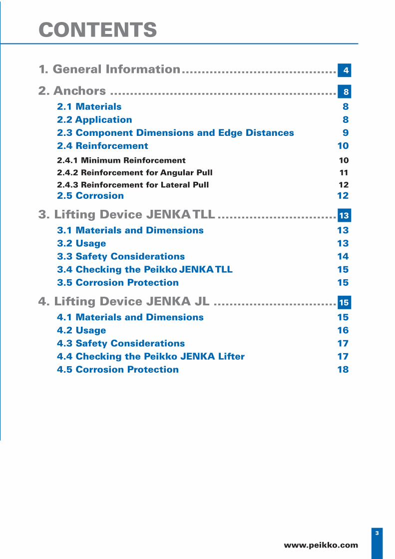
1. General Information ....................................... 4
2. Anchors ......................................................... 8
2.1 Materials 82.2 Application 82.3 Component Dimensions and Edge Distances 92.4 Reinforcement 102.4.1 Minimum Reinforcement 102.4.2 Reinforcement for Angular Pull 112.4.3 Reinforcement for Lateral Pull 122.5 Corrosion 12
3. Lifting Device JENKA TLL .............................. 13
3.1 Materials and Dimensions 133.2 Usage 133.3 Safety Considerations 143.4 Checking the Peikko JENKA TLL 153.5 Corrosion Protection 15
4. Lifting Device JENKA JL ............................... 15
4.1 Materials and Dimensions 154.2 Usage 164.3 Safety Considerations 174.4 Checking the Peikko JENKA Lifter 174.5 Corrosion Protection 18
CONTENTS
4
JENKA System
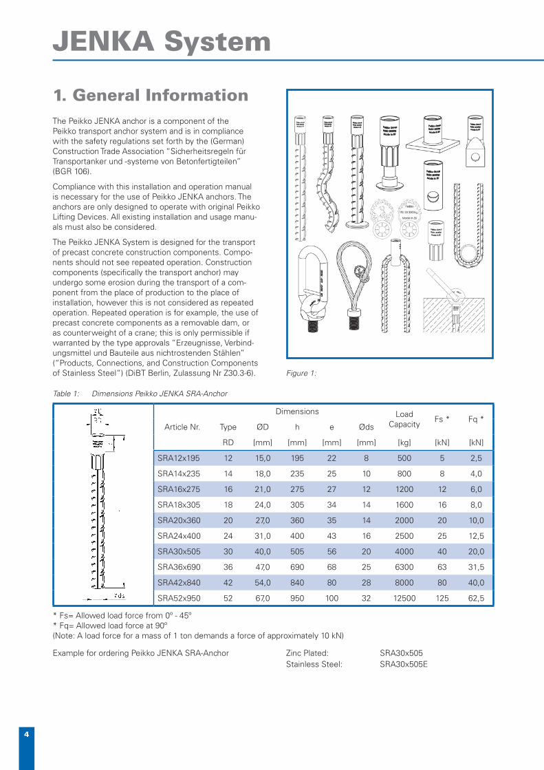
1. General InformationThe Peikko JENKA anchor is a component of the Peikko transport anchor system and is in compliance with the safety regulations set forth by the (German) Construction Trade Association “Sicherheitsregeln für Transportanker und -systeme von Betonfertigteilen” (BGR 106).
Compliance with this installation and operation manual is necessary for the use of Peikko JENKA anchors. The anchors are only designed to operate with original Peikko Lifting Devices. All existing installation and usage manu-als must also be considered.
The Peikko JENKA System is designed for the transport of precast concrete construction components. Compo-nents should not see repeated operation. Construction components (specifi cally the transport anchor) may undergo some erosion during the transport of a com-ponent from the place of production to the place of installation, however this is not considered as repeated operation. Repeated operation is for example, the use of precast concrete components as a removable dam, or as counterweight of a crane; this is only permissible if warranted by the type approvals “Erzeugnisse, Verbind-ungsmittel und Bauteile aus nichtrostenden Stählen” (“Products, Connections, and Construction Components of Stainless Steel”) (DiBT Berlin, Zulassung Nr Z30.3-6).
Table 1: Dimensions Peikko JENKA SRA-Anchor
Article Nr.
Dimensions Load Capacity
Fs * Fq *Type ØD h e Øds
RD [mm] [mm] [mm] [mm] [kg] [kN] [kN]
SRA12x195 12 15,0 195 22 8 500 5 2,5
SRA14x235 14 18,0 235 25 10 800 8 4,0
SRA16x275 16 21,0 275 27 12 1200 12 6,0
SRA18x305 18 24,0 305 34 14 1600 16 8,0
SRA20x360 20 27,0 360 35 14 2000 20 10,0
SRA24x400 24 31,0 400 43 16 2500 25 12,5
SRA30x505 30 40,0 505 56 20 4000 40 20,0
SRA36x690 36 47,0 690 68 25 6300 63 31,5
SRA42x840 42 54,0 840 80 28 8000 80 40,0
SRA52x950 52 67,0 950 100 32 12500 125 62,5
* Fs= Allowed load force from 0º - 45º* Fq= Allowed load force at 90º(Note: A load force for a mass of 1 ton demands a force of approximately 10 kN)
Example for ordering Peikko JENKA SRA-Anchor Zinc Plated: SRA30x505Stainless Steel: SRA30x505E
Figure 1:
5
www.peikko.com
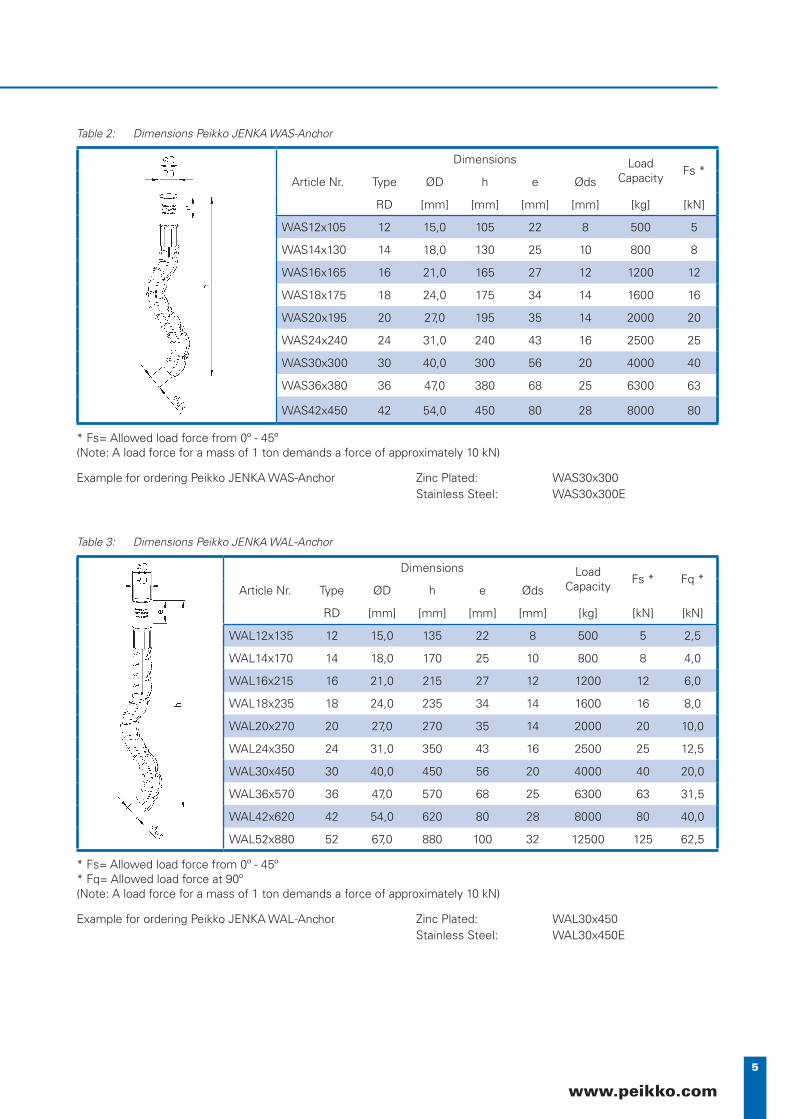
Table 2: Dimensions Peikko JENKA WAS-Anchor
Article Nr.
Dimensions Load Capacity
Fs *Type ØD h e Øds
RD [mm] [mm] [mm] [mm] [kg] [kN]
WAS12x105 12 15,0 105 22 8 500 5
WAS14x130 14 18,0 130 25 10 800 8
WAS16x165 16 21,0 165 27 12 1200 12
WAS18x175 18 24,0 175 34 14 1600 16
WAS20x195 20 27,0 195 35 14 2000 20
WAS24x240 24 31,0 240 43 16 2500 25
WAS30x300 30 40,0 300 56 20 4000 40
WAS36x380 36 47,0 380 68 25 6300 63
WAS42x450 42 54,0 450 80 28 8000 80
* Fs= Allowed load force from 0º - 45º(Note: A load force for a mass of 1 ton demands a force of approximately 10 kN)
Example for ordering Peikko JENKA WAS-Anchor Zinc Plated: WAS30x300Stainless Steel: WAS30x300E
Table 3: Dimensions Peikko JENKA WAL-Anchor
Article Nr.
Dimensions Load Capacity
Fs * Fq *Type ØD h e Øds
RD [mm] [mm] [mm] [mm] [kg] [kN] [kN]
WAL12x135 12 15,0 135 22 8 500 5 2,5
WAL14x170 14 18,0 170 25 10 800 8 4,0
WAL16x215 16 21,0 215 27 12 1200 12 6,0
WAL18x235 18 24,0 235 34 14 1600 16 8,0
WAL20x270 20 27,0 270 35 14 2000 20 10,0
WAL24x350 24 31,0 350 43 16 2500 25 12,5
WAL30x450 30 40,0 450 56 20 4000 40 20,0
WAL36x570 36 47,0 570 68 25 6300 63 31,5
WAL42x620 42 54,0 620 80 28 8000 80 40,0
WAL52x880 52 67,0 880 100 32 12500 125 62,5
* Fs= Allowed load force from 0º - 45º* Fq= Allowed load force at 90º(Note: A load force for a mass of 1 ton demands a force of approximately 10 kN)
Example for ordering Peikko JENKA WAL-Anchor Zinc Plated: WAL30x450Stainless Steel: WAL30x450E
6
JENKA System
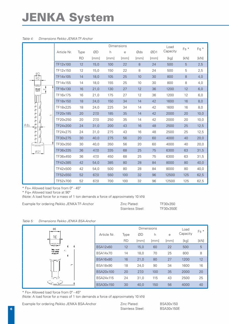
Table 4: Dimensions Peikko JENKA TF-Anchor
Article Nr.
Dimensions Load Capacity
Fs * Fq *Type ØD h e Øds ØD1
RD [mm] [mm] [mm] [mm] [mm] [kg] [kN] [kN]
TF12x100 12 15,0 100 22 8 24 500 5 2,5
TF12x150 12 15,0 150 22 8 24 500 5 2,5
TF14x105 14 18,0 105 25 10 30 800 8 4,0
TF14x155 14 18,0 155 25 10 30 800 8 4,0
TF16x130 16 21,0 130 27 12 36 1200 12 6,0
TF16x175 16 21,0 175 27 12 36 1200 12 6,0
TF18x150 18 24,0 150 34 14 42 1600 16 8,0
TF18x225 18 24,0 225 34 14 42 1600 16 8,0
TF20x185 20 27,0 185 35 14 42 2000 20 10,0
TF20x250 20 27,0 250 35 14 42 2000 20 10,0
TF24x200 24 31,0 200 43 16 48 2500 25 12,5
TF24x275 24 31,0 275 43 16 48 2500 25 12,5
TF30x275 30 40,0 275 56 20 60 4000 40 20,0
TF30x350 30 40,0 350 56 20 60 4000 40 20,0
TF36x335 36 47,0 335 68 25 75 6300 63 31,5
TF36x450 36 47,0 450 68 25 75 6300 63 31,5
TF42x385 42 54,0 385 80 28 84 8000 80 40,0
TF42x500 42 54,0 500 80 28 84 8000 80 40,0
TF52x550 52 67,0 550 100 32 96 12500 125 62,5
TF52x700 52 67,0 700 100 32 96 12500 125 62,5
* Fs= Allowed load force from 0º - 45º* Fq= Allowed load force at 90º(Note: A load force for a mass of 1 ton demands a force of approximately 10 kN)
Example for ordering Peikko JENKA TF-Anchor Zinc Plated: TF30x350Stainless Steel: TF30x350E
Table 5: Dimensions Peikko JENKA BSA-Anchor
Article Nr.
Dimensions Load Capacity
Fs *Type ØD h e
RD [mm] [mm] [mm] [kg] [kN]
BSA12x60 12 15,0 60 22 500 5
BSA14x70 14 18,0 70 25 800 8
BSA16x80 16 21,0 80 27 1200 12
BSA18x90 18 24,0 90 34 1600 16
BSA20x100 20 27,0 100 35 2000 20
BSA24x115 24 31,0 115 43 2500 25
BSA30x150 30 40,0 150 56 4000 40
* Fs= Allowed load force from 0º - 45º(Note: A load force for a mass of 1 ton demands a force of approximately 10 kN)
Example for ordering Peikko JENKA BSA-Anchor Zinc Plated: BSA30x150Stainless Steel: BSA30x150E
7
www.peikko.com
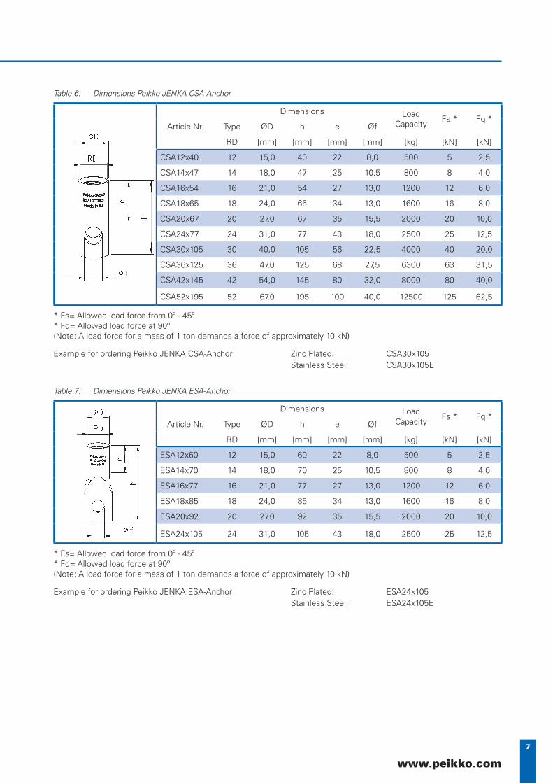
Table 6: Dimensions Peikko JENKA CSA-Anchor
Article Nr.
Dimensions Load Capacity
Fs * Fq *Type ØD h e Øf
RD [mm] [mm] [mm] [mm] [kg] [kN] [kN]
CSA12x40 12 15,0 40 22 8,0 500 5 2,5
CSA14x47 14 18,0 47 25 10,5 800 8 4,0
CSA16x54 16 21,0 54 27 13,0 1200 12 6,0
CSA18x65 18 24,0 65 34 13,0 1600 16 8,0
CSA20x67 20 27,0 67 35 15,5 2000 20 10,0
CSA24x77 24 31,0 77 43 18,0 2500 25 12,5
CSA30x105 30 40,0 105 56 22,5 4000 40 20,0
CSA36x125 36 47,0 125 68 27,5 6300 63 31,5
CSA42x145 42 54,0 145 80 32,0 8000 80 40,0
CSA52x195 52 67,0 195 100 40,0 12500 125 62,5
* Fs= Allowed load force from 0º - 45º* Fq= Allowed load force at 90º(Note: A load force for a mass of 1 ton demands a force of approximately 10 kN)
Example for ordering Peikko JENKA CSA-Anchor Zinc Plated: CSA30x105Stainless Steel: CSA30x105E
Table 7: Dimensions Peikko JENKA ESA-Anchor
Article Nr.
Dimensions Load Capacity
Fs * Fq *Type ØD h e Øf
RD [mm] [mm] [mm] [mm] [kg] [kN] [kN]
ESA12x60 12 15,0 60 22 8,0 500 5 2,5
ESA14x70 14 18,0 70 25 10,5 800 8 4,0
ESA16x77 16 21,0 77 27 13,0 1200 12 6,0
ESA18x85 18 24,0 85 34 13,0 1600 16 8,0
ESA20x92 20 27,0 92 35 15,5 2000 20 10,0
ESA24x105 24 31,0 105 43 18,0 2500 25 12,5
* Fs= Allowed load force from 0º - 45º* Fq= Allowed load force at 90º(Note: A load force for a mass of 1 ton demands a force of approximately 10 kN)
Example for ordering Peikko JENKA ESA-Anchor Zinc Plated: ESA24x105Stainless Steel: ESA24x105E

8
JENKA System
Table 8: Dimensions Peikko JENKA PSA-Anchor
Article Nr.
Dimensions Load Capacity
Fs *Type ØD h a b t
RD [mm] [mm] [mm] [mm] [mm] [kg] [kN]
PSA12x30 12 15,0 30 35 25 4 500 5
PSA14x33 14 18,0 33 35 35 4 800 8
PSA16x35 16 21,0 35 50 35 4 1200 12
PSA18x44 18 24,0 44 60 45 5 1600 16
PSA20x47 20 27,0 47 60 60 5 2000 20
PSA24x54 24 31,0 54 80 60 5 2500 25
PSA30x72 30 40,0 72 100 80 6 4000 40
PSA36x84 36 47,0 84 130 100 6 6300 63
PSA42x98 42 54,0 98 130 130 8 8000 80
PSA52x117 52 67,0 117 150 130 10 12500 125
* Fs= Allowed load force from 0º - 45º(Note: A load force for a mass of 1 ton demands a force of approximately 10 kN)
Example for ordering Peikko JENKA PSA-Anchor Zinc Plated: PSA30x72Stainless Steel: PSA30x72E
Anchors of the Peikko JENKA Sys-tem are identifi ed by markings in the socket. Manufac-turer, load capac-ity and thread type are printed to the surface. The correct allocation of JENKA Anchor and JENKA Lifting Device is given with this mark-ing. Mistakes are avoided due to these markings.
2. Anchors
2.1 Materials
Sockets of the Peikko JENKA System are constructed from precision steel tubes of exceptional quality. The sockets are used in combination with BST500S, the pressed variant of Peikko JENKA anchors. For other types, special screws and fl at steel is used.
The anchors are generally protected from corrosion through electro zinc plating, excluding the rebars. Anchors made of stainless steel are also available. The pressed stainless anchors are protected with a sealing agent on the inside of the threaded socket.
Figure 2: Marking
2.2 Application
Installation and application
A Peikko JENKA anchor nailplate and identifi cation ring is used when installing the anchor into the formwork.The nailplate is usually installed with either nails or with a hot glue gun. For steel forms JENKA NPM magnetic installation plate is used. The nailplate forms the recess so that the Peikko lifting device can be connected. It is necessary to use original NPP Peikko JENKA nailplates when Peikko JENKA Lifter is used. The rotation sym-metric Peikko JENKA anchor (Type SRA, TF, BSA) does not require further attention in anchor installation. For all other Peikko JENKA anchors, the waved ends and rein-forcement stirrups respectively, must always be parallel to the lengthwise direction of the component.
The load transmission to the concrete is accomplished by the mechanical bond stress of the reinforced concrete, this is conditioned by the forming and implementation of the JENKA anchor. With this system construction compo-nents, particularly thin components, can safely undergo application of heavy forces. For massive components we recommend the use of JENKA WAL Anchors or the Peikko JENKA TF Anchor. The forces are applied to the waved part of the anchor and the forged foot encased in the concrete.
At the time of fi rst lifting, the concrete must have a compressive strength of at least 15 N/mm2. Dynamic and adhesive forces which affect to lifting load must be checked by the user. Incorrectly used or damaged Peikko JENKA anchors may not be installed in precast com-ponents. Welding or other modifi cations to the Peikko JENKA anchor (especially bending) are prohibited.
9
www.peikko.com
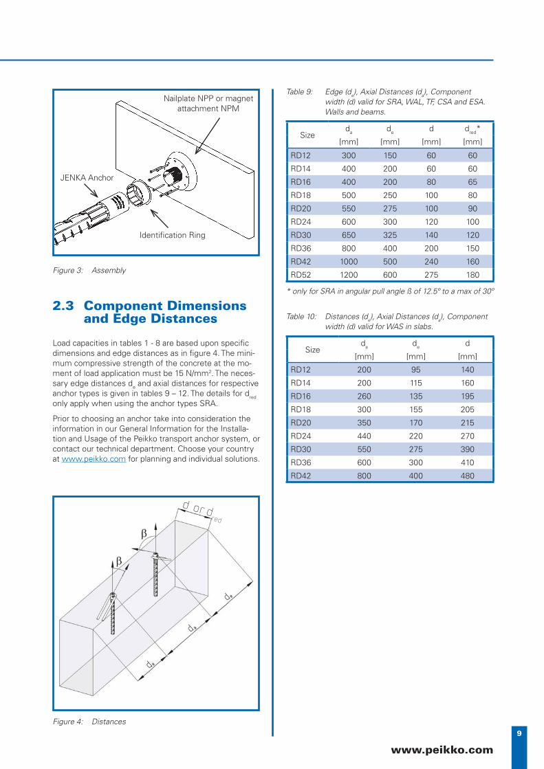
2.3 Component Dimensions and Edge Distances
Load capacities in tables 1 - 8 are based upon specifi c dimensions and edge distances as in fi gure 4. The mini-mum compressive strength of the concrete at the mo-ment of load application must be 15 N/mm2. The neces-sary edge distances de and axial distances for respective anchor types is given in tables 9 – 12. The details for dred only apply when using the anchor types SRA.
Prior to choosing an anchor take into consideration the information in our General Information for the Installa-tion and Usage of the Peikko transport anchor system, or contact our technical department. Choose your country at www.peikko.com for planning and individual solutions.
Figure 3: Assembly
Nailplate NPP or magnet attachment NPM
Identifi cation Ring
JENKA Anchor
Table 9: Edge (de), Axial Distances (da), Componentwidth (d) valid for SRA, WAL, TF, CSA and ESA. Walls and beams.
Sizeda de d dred*
[mm] [mm] [mm] [mm]
RD12 300 150 60 60
RD14 400 200 60 60
RD16 400 200 80 65
RD18 500 250 100 80
RD20 550 275 100 90
RD24 600 300 120 100
RD30 650 325 140 120
RD36 800 400 200 150
RD42 1000 500 240 160
RD52 1200 600 275 180
* only for SRA in angular pull angle ß of 12.5º to a max of 30º
Table 10: Distances (de), Axial Distances (da), Componentwidth (d) valid for WAS in slabs.
Sizeda de d
[mm] [mm] [mm]
RD12 200 95 140
RD14 200 115 160
RD16 260 135 195
RD18 300 155 205
RD20 350 170 215
RD24 440 220 270
RD30 550 275 390
RD36 600 300 410
RD42 800 400 480
Figure 4: Distances
d or dred
10
JENKA System
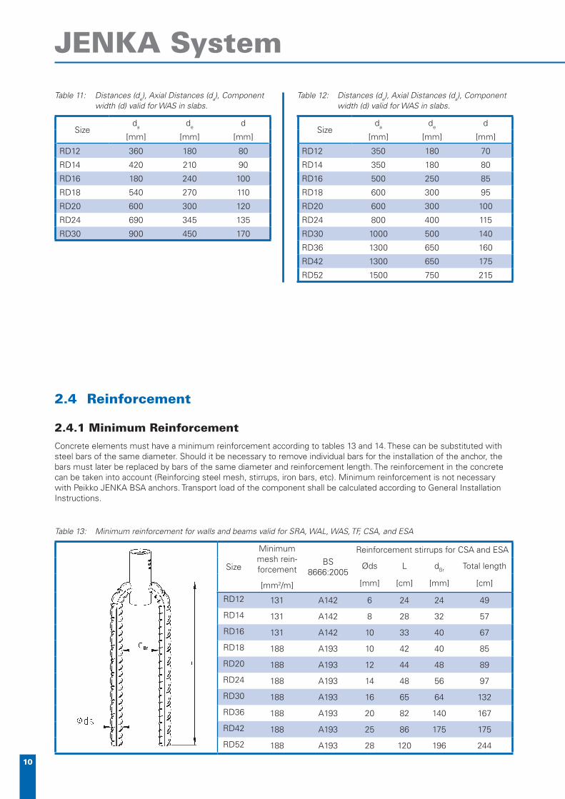
Table 11: Distances (de), Axial Distances (da), Componentwidth (d) valid for WAS in slabs.
Sizeda de d
[mm] [mm] [mm]
RD12 360 180 80
RD14 420 210 90
RD16 180 240 100
RD18 540 270 110
RD20 600 300 120
RD24 690 345 135
RD30 900 450 170
Table 12: Distances (de), Axial Distances (da), Componentwidth (d) valid for WAS in slabs.
Sizeda de d
[mm] [mm] [mm]
RD12 350 180 70
RD14 350 180 80
RD16 500 250 85
RD18 600 300 95
RD20 600 300 100
RD24 800 400 115
RD30 1000 500 140
RD36 1300 650 160
RD42 1300 650 175
RD52 1500 750 215
2.4 Reinforcement
2.4.1 Minimum ReinforcementConcrete elements must have a minimum reinforcement according to tables 13 and 14. These can be substituted with steel bars of the same diameter. Should it be necessary to remove individual bars for the installation of the anchor, the bars must later be replaced by bars of the same diameter and reinforcement length. The reinforcement in the concrete can be taken into account (Reinforcing steel mesh, stirrups, iron bars, etc). Minimum reinforcement is not necessary with Peikko JENKA BSA anchors. Transport load of the component shall be calculated according to General Installation Instructions.
Table 13: Minimum reinforcement for walls and beams valid for SRA, WAL, WAS, TF, CSA, and ESA
Size
Minimum mesh rein-forcement
[mm2/m]
BS 8666:2005
Reinforcement stirrups for CSA and ESA
Øds L dBr Total length
[mm] [cm] [mm] [cm]
RD12 131 A142 6 24 24 49
RD14 131 A142 8 28 32 57
RD16 131 A142 10 33 40 67
RD18 188 A193 10 42 40 85
RD20 188 A193 12 44 48 89
RD24 188 A193 14 48 56 97
RD30 188 A193 16 65 64 132
RD36 188 A193 20 82 140 167
RD42 188 A193 25 86 175 175
RD52 188 A193 28 120 196 244

11
www.peikko.com
Table 14: Minimum reinforcement of slabs valid for PSA
Size
Minimum mesh
reinforce-ment
[mm2/m] BS
866
6:20
05
num
ber
Basic reinforcement
Øds L a b
[Pc.] [mm] [mm] [mm] [mm]
RD12 131 A142 2 6 250 60 60
RD14 131 A142 2 6 360 60 70
RD16 131 A142 2 8 420 90 70
RD18 188 A193 2 8 530 90 80
RD20 188 A193 2 8 640 90 80
RD24 188 A193 2 10 640 90 100
RD30 221 A252 2 12 830 90 110
RD36 221 A252 2 14 1140 140 120
RD42 513 2 16 1250 140 120
RD52 513 2 20 1530 140 150
Figure 5: Reinforcement Stirrups
Figure 6: Installation position
2.4.2 Reinforcement for Angular PullIn the case of loads in angular pull, a reinforcement stirrup must be applied with pressure contact at the angular point counteracting the direction of pull (table 15 and fi gure 7). In case of a max. angular pull of 30° it is possible to adjust the reinforcement stirrup in length and diameter.
Table 15: Angular pull reinforcement valid for allPeikko JENKA anchors
Size
For Component widthd
12,5° ≤ β ≤ 45°
For Component widthd or. dred
12,5° ≤ β ≤ 30°
Øds L dBr Øds L dBr
[mm] [mm] [mm] [mm] [mm] [mm]
RD12 6 150 24 6 150 24
RD14 6 200 24 6 200 24
RD16 8 200 32 6 250 24
RD18 8 250 32 8 200 32
RD20 8 300 32 8 250 32
RD24 10 300 40 8 300 32
RD30 12 400 48 10 350 40
RD36 14 550 56 12 450 48
RD42 16 600 64 14 600 56
RD52 20 750 140 16 700 64
Figure 7: Reinforcement for angular pull
Figure 8: Arrangement of the reinforcement for angular pull
d or dred

12
JENKA System
2.4.3 Reinforcement for Lateral PullA load in lateral pull with γ ≥ 15º requires an additional reinforcement to be incorporated following table 16 in the face counteracting the direction of pull (fi gure 11). Loads in lateral pull (with the use of chain overhead conveyors) requires no further measures, as the stirrup provides for this load as well. During lowering and rais-ing of the component, the direction of the reinforcement should always be checked (fi gure 11). Lateral lifting is allowed only for components with minimum thickness “d” according to table 9.
Attention: for Peikko JENKA anchor types BSA, PSA, and WAS, lateral pull is not permissible.
Table 16: Reinforcement for Lateral Pull (necessary if γ ≥ 15°)
SizeØds1 L h H dBr B Øds2
[mm] [mm] [mm] [mm] [mm] [mm] [mm]
RD12 6 270 23 35 24 280 8
RD14 6 350 28 42 24 350 12
RD16 8 420 33 49 32 400 12
RD18 8 460 39 55 32 450 12
RD20 10 490 44 64 40 490 14
RD24 12 520 51 75 48 550 14
RD30 12 570 68 92 48 580 16
RD36 14 690 90 118 56 700 16
RD42 16 830 111 143 64 850 20
RD52 20 930 134 174 140 1000 20
Figure 9: Angle of Lateral Pull γ
Figure 10: Reinforcement for Lateral Pull
Figure 11: Installation of Lateral Pull reinforcement. Reinforcement must be in contact with the socket surface.
2.5 Corrosion
Lifetime of installed Peikko JENKA Anchors is limited due to corrosion. Even through the use of electric zinc plated anchors, corrosion damage can occur and cause rust damage to the component surface. Corrosion dam-age can be avoided if after fi nal placement the anchor is covered with mortar and suffi cient concrete covering. If the JENKA anchor is to be consistently used in outdoor environments, Industrial environments, or in the vicinity of sea, we recommend the use of Peikko JENKA an-chors made of stainless steel. Electric zinc plated Peikko JENKA anchors should only be stored for a longer time in dry environmental. To protect the anchors against rust we recommend to use JENKA CPP plastic plugs.
Lateral Pull
Lateral-Angular Pull
13
www.peikko.com
3. Lifting Device JENKA TLL
3.1 Materials and Dimensions
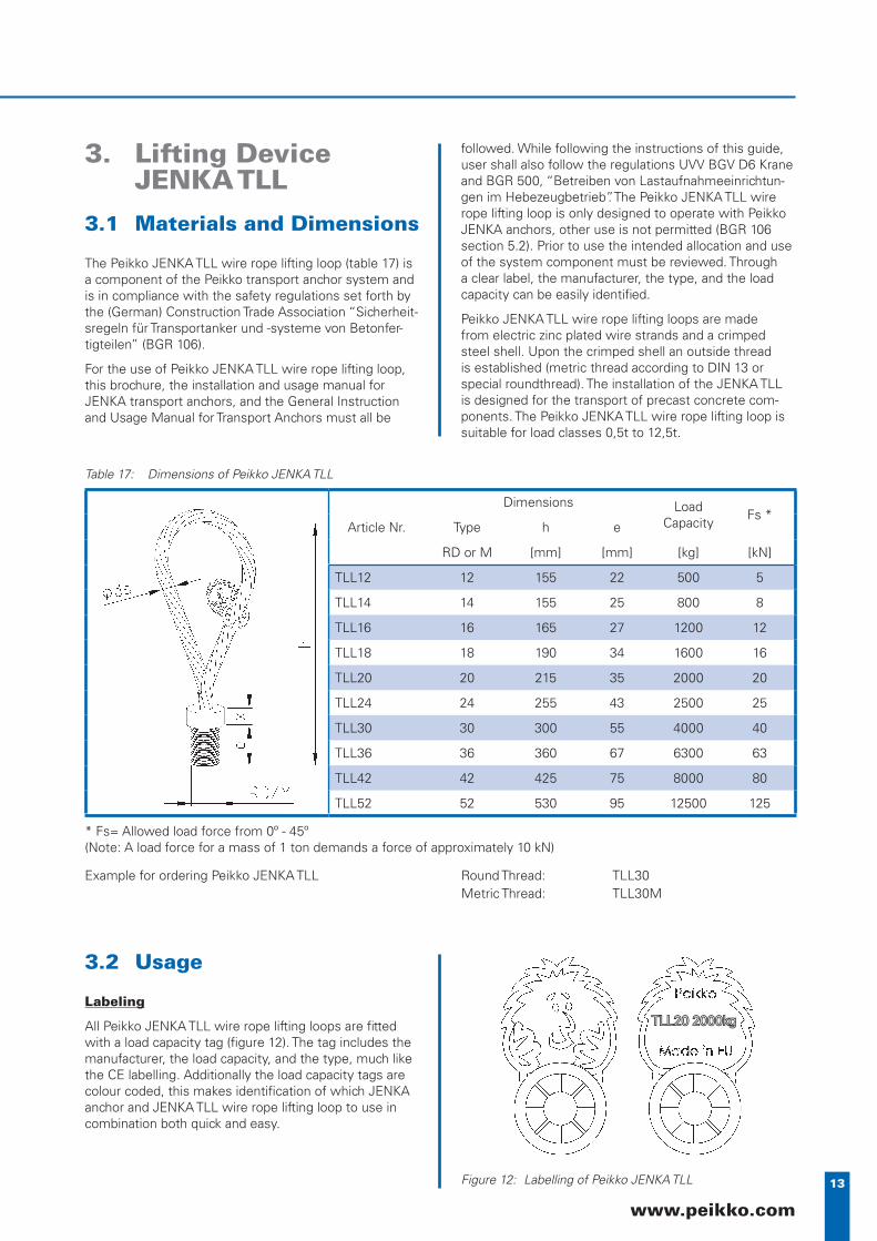
The Peikko JENKA TLL wire rope lifting loop (table 17) is a component of the Peikko transport anchor system and is in compliance with the safety regulations set forth by the (German) Construction Trade Association “Sicherheit-sregeln für Transportanker und -systeme von Betonfer-tigteilen” (BGR 106).
For the use of Peikko JENKA TLL wire rope lifting loop, this brochure, the installation and usage manual for JENKA transport anchors, and the General Instruction and Usage Manual for Transport Anchors must all be
followed. While following the instructions of this guide, user shall also follow the regulations UVV BGV D6 Krane and BGR 500, “Betreiben von Lastaufnahmeeinrichtun-gen im Hebezeugbetrieb”. The Peikko JENKA TLL wire rope lifting loop is only designed to operate with Peikko JENKA anchors, other use is not permitted (BGR 106 section 5.2). Prior to use the intended allocation and use of the system component must be reviewed. Through a clear label, the manufacturer, the type, and the load capacity can be easily identifi ed.
Peikko JENKA TLL wire rope lifting loops are made from electric zinc plated wire strands and a crimped steel shell. Upon the crimped shell an outside thread is established (metric thread according to DIN 13 or special roundthread). The installation of the JENKA TLL is designed for the transport of precast concrete com-ponents. The Peikko JENKA TLL wire rope lifting loop is suitable for load classes 0,5t to 12,5t.
Table 17: Dimensions of Peikko JENKA TLL
Article Nr.
Dimensions Load Capacity
Fs *Type h e
RD or M [mm] [mm] [kg] [kN]
TLL12 12 155 22 500 5
TLL14 14 155 25 800 8
TLL16 16 165 27 1200 12
TLL18 18 190 34 1600 16
TLL20 20 215 35 2000 20
TLL24 24 255 43 2500 25
TLL30 30 300 55 4000 40
TLL36 36 360 67 6300 63
TLL42 42 425 75 8000 80
TLL52 52 530 95 12500 125
* Fs= Allowed load force from 0º - 45º(Note: A load force for a mass of 1 ton demands a force of approximately 10 kN)
Example for ordering Peikko JENKA TLL Round Thread: TLL30Metric Thread: TLL30M
3.2 Usage
Labeling
All Peikko JENKA TLL wire rope lifting loops are fi tted with a load capacity tag (fi gure 12). The tag includes the manufacturer, the load capacity, and the type, much like the CE labelling. Additionally the load capacity tags are colour coded, this makes identifi cation of which JENKA anchor and JENKA TLL wire rope lifting loop to use in combination both quick and easy.
Figure 12: Labelling of Peikko JENKA TLL
TLL20 2000kgTLL20 2000kg
14
JENKA System
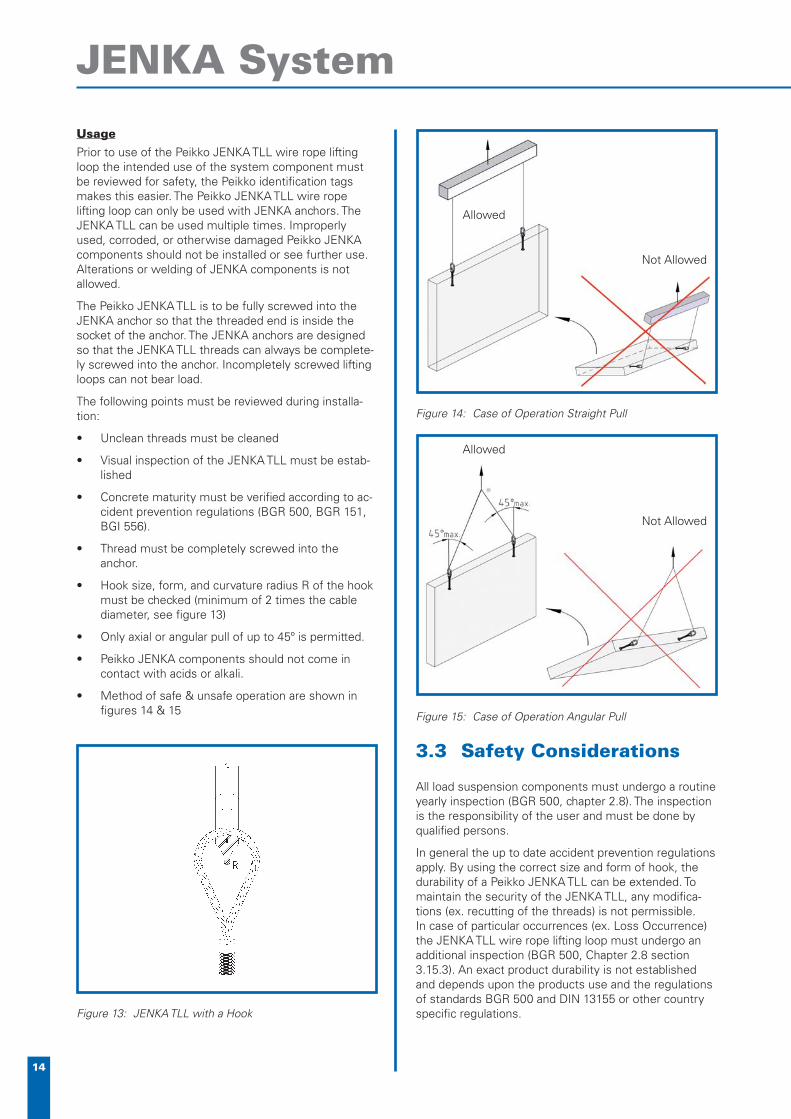
UsagePrior to use of the Peikko JENKA TLL wire rope lifting loop the intended use of the system component must be reviewed for safety, the Peikko identifi cation tags makes this easier. The Peikko JENKA TLL wire rope lifting loop can only be used with JENKA anchors. The JENKA TLL can be used multiple times. Improperly used, corroded, or otherwise damaged Peikko JENKA components should not be installed or see further use. Alterations or welding of JENKA components is not allowed.
The Peikko JENKA TLL is to be fully screwed into the JENKA anchor so that the threaded end is inside the socket of the anchor. The JENKA anchors are designed so that the JENKA TLL threads can always be complete-ly screwed into the anchor. Incompletely screwed lifting loops can not bear load.
The following points must be reviewed during installa-tion:
Unclean threads must be cleaned•
Visual inspection of the JENKA TLL must be estab-• lished
Concrete maturity must be verifi ed according to ac-• cident prevention regulations (BGR 500, BGR 151, BGI 556).
Thread must be completely screwed into the • anchor.
Hook size, form, and curvature radius R of the hook • must be checked (minimum of 2 times the cable diameter, see fi gure 13)
Only axial or angular pull of up to 45º is permitted.•
Peikko JENKA components should not come in • contact with acids or alkali.
Method of safe & unsafe operation are shown in • fi gures 14 & 15
Figure 13: JENKA TLL with a Hook
3.3 Safety Considerations
All load suspension components must undergo a routine yearly inspection (BGR 500, chapter 2.8). The inspection is the responsibility of the user and must be done by qualifi ed persons.
In general the up to date accident prevention regulations apply. By using the correct size and form of hook, the durability of a Peikko JENKA TLL can be extended. To maintain the security of the JENKA TLL, any modifi ca-tions (ex. recutting of the threads) is not permissible. In case of particular occurrences (ex. Loss Occurrence) the JENKA TLL wire rope lifting loop must undergo an additional inspection (BGR 500, Chapter 2.8 section 3.15.3). An exact product durability is not established and depends upon the products use and the regulations of standards BGR 500 and DIN 13155 or other country specifi c regulations.
Figure 14: Case of Operation Straight Pull
Figure 15: Case of Operation Angular Pull
Not Allowed
Allowed
Not Allowed
Allowed
15
www.peikko.com
3.4 Checking the Peikko
JENKA TLL
The amount of inspection and the required concrete maturity for loading and load capacity components conforms to the regulations in BGR section 3.15.4. The following is a list of inspection criteria to be reviewed.
Damage to the threads•
Kinks•
Breaking of strands •
Loosening of the exterior length in free length•
Corrosion marks•
Damage or heavy wear upon the loop or the con-• nection head.
Any wire breaks.•
The complete extent of the inspection can be found in BGR 500 chapter 2.8, 3.15.1.
3.5 Corrosion Protection
The durability of reinforced concrete components with installed Peikko JENKA TLL load suspension compo-nents is assured, damage through corrosion is limited. Lifting loops can leave corrosion scars upon the surface of a concrete component.
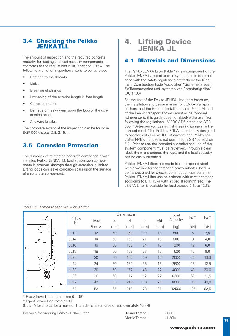
4. Lifting Device JENKA JL
4.1 Materials and Dimensions
The Peikko JENKA Lifter (table 17) is a component of the Peikko JENKA transport anchor system and is in compli-ance with the safety regulations set forth by the (Ger-man) Construction Trade Association “Sicherheitsregeln für Transportanker und -systeme von Betonfertigteilen” (BGR 106).
For the use of the Peikko JENKA Lifter, this brochure, the installation and usage manual for JENKA transport anchors, and the General Installation and Usage Manual of the Peikko transport anchors must all be followed. Adherence to this guide does not absolve the user from following the regulations UVV BGV D6 Krane and BGR 500, “Betreiben von Lastaufnahmeeinrichtungen im He-bezeugbetrieb”. The Peikko JENKA Lifter is only designed to operate with Peikko JENKA anchors and Peikko nail-plates NPP, other use is not permitted (BGR 106 section 5.2). Prior to use the intended allocation and use of the system component must be reviewed. Through a clear label, the manufacturer, the type, and the load capacity can be easily identifi ed.
Peikko JENKA Lifters are made from tempered steel with a welded forged threaded screw adapter. Installa-tion is designed for precast construction components. Peikko JENKA Lifter can be ordered with metric threads according to DIN 13 or with a special roundthread. The JENKA Lifter is available for load classes 0.5t to 12.5t.
Table 18: Dimensions Peikko JENKA Lifter
Article Nr.
Dimensions Load Capacity
Fs * Fq *Type B H e Ød
R or M [mm] [mm] [mm] [mm] [kg] [kN] [kN]
JL12 12 50 150 19 13 500 5 2,5
JL14 14 50 150 21 13 800 8 4,0
JL16 16 50 150 24 13 1200 12 6,0
JL18 18 50 162 27 16 1600 16 8,0
JL20 20 50 162 29 16 2000 20 10,0
JL24 24 50 162 35 16 2500 25 12,5
JL30 30 50 177 43 22 4000 40 20,0
JL36 36 50 177 52 22 6300 63 31,5
JL42 42 65 218 60 26 8000 80 40,0
JL52 52 65 218 73 26 12500 125 62,5
* Fs= Allowed load force from 0º - 45º* Fq= Allowed load force at 90º(Note: A load force for a mass of 1 ton demands a force of approximately 10 kN)
Example for ordering Peikko JENKA Lifter Round Thread: JL30Metric Thread: JL30M

16
JENKA System
4.2 Usage
Labelling
All Peikko JENKA Lifters are imprinted with a perma-nent marking on its ring (fi gure 16). This includes the manufacturer, the load capacity, and the type, much like the CE labelling. Finding compatible Peikko anchors and Lifters is possible through these markings.
Usage
The installation of the Peikko JENKA Lifter must take into consideration the General Information for Installa-tion of Peikko transport anchors, this brochure, and the usage manual for Peikko JENKA anchors. Prior to use the intended allocation and use of the system compo-nent must be reviewed. The load suspension devices of the Peikko JENKA System (JENKA TLL and JENKA Lifter) are only designed to operate with the Peikko JENKA anchor. The JENKA load suspension devices can undergo multiple loads from the place of casting to the place of installation. Improperly used, corroded, or oth-erwise damaged Peikko JENKA components should not be installed or see further use. Alterations or welding of JENKA components is not allowed.
The following points must be reviewed during installa-tion.
Unclean threads must be cleaned•
Visual inspection of the JENKA JL must be estab-• lished.
Concrete maturity must be verifi ed according to ac-• cident prevention regulations (BGR 500, BGI 556).
Thread is completely screwed into the anchor.•
Appropriate lifting components (hook size and hook • form) is used.
Peikko JENKA components should not come in • contact with acids or lye.
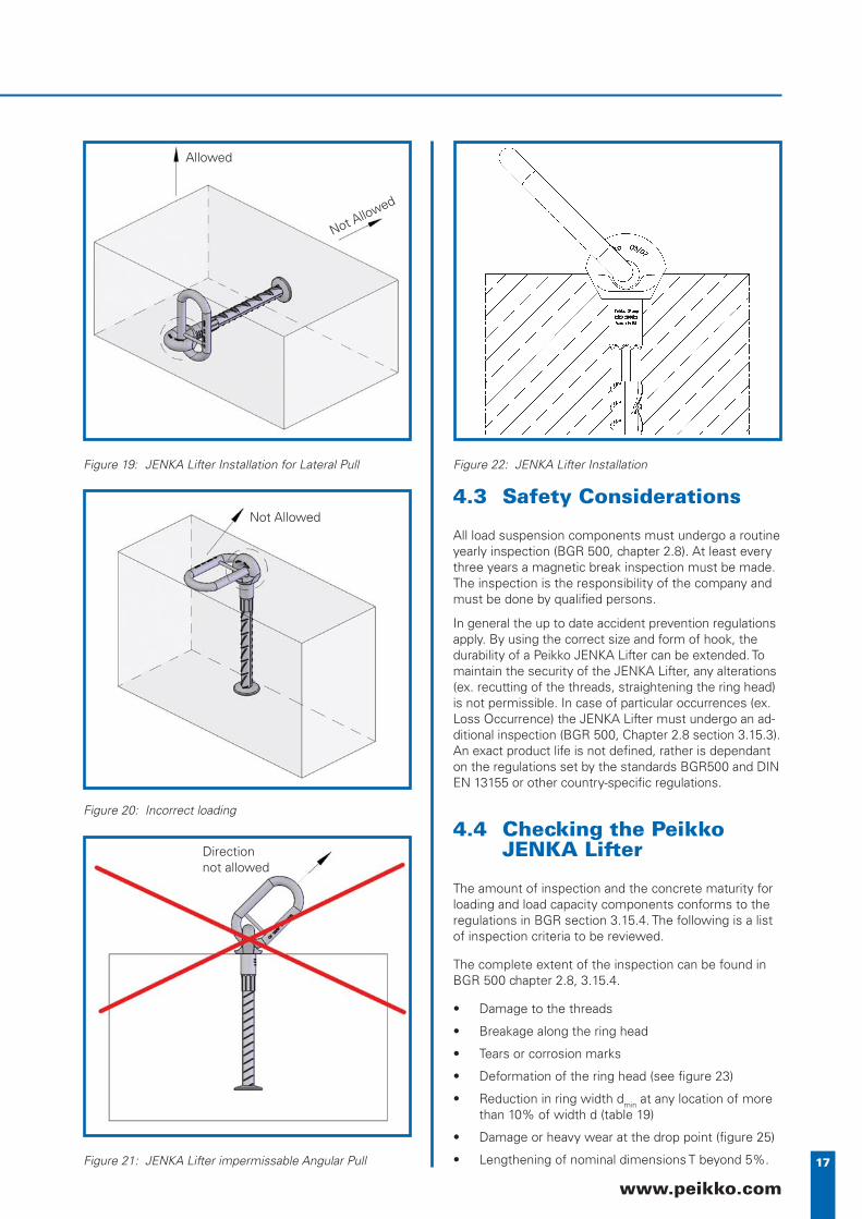
The Peikko JENKA Lifter should only undergo loads • from the directions shown in fi gures 17 - 18, loads as shown in fi gures 19 - 21 are impermissible.
The Peikko JENKA Lifter is used with the JENKA nail-plate NPP. After fully screwed into place, the load sus-pension device is ready to apply force to the concrete (fi gure 22). For the alignment in the direction of pull, the Lifter can be unscrewed a maximum of half a rotation.
Improper direction of pull (Pulling over corners, or in angular pull greater than 45º) can lead to damage of the ring or the threaded head. The concrete maturity is greatly effected.
Figure 16: JENKA Lifter Identifi cation
Figure 17: JENKA Lifter Installation for Axial and Angular Pull
Figure 18: JENKA Lifter Installation for Lateral Pull
Allowed
Not Allowed
17
www.peikko.com
4.3 Safety Considerations
All load suspension components must undergo a routine yearly inspection (BGR 500, chapter 2.8). At least every three years a magnetic break inspection must be made. The inspection is the responsibility of the company and must be done by qualifi ed persons.
In general the up to date accident prevention regulations apply. By using the correct size and form of hook, the durability of a Peikko JENKA Lifter can be extended. To maintain the security of the JENKA Lifter, any alterations (ex. recutting of the threads, straightening the ring head) is not permissible. In case of particular occurrences (ex. Loss Occurrence) the JENKA Lifter must undergo an ad-ditional inspection (BGR 500, Chapter 2.8 section 3.15.3). An exact product life is not defi ned, rather is dependant on the regulations set by the standards BGR500 and DIN EN 13155 or other country-specifi c regulations.
4.4 Checking the Peikko JENKA Lifter
The amount of inspection and the concrete maturity for loading and load capacity components conforms to the regulations in BGR section 3.15.4. The following is a list of inspection criteria to be reviewed.
The complete extent of the inspection can be found in BGR 500 chapter 2.8, 3.15.4.
Damage to the threads•
Breakage along the ring head •
Tears or corrosion marks•
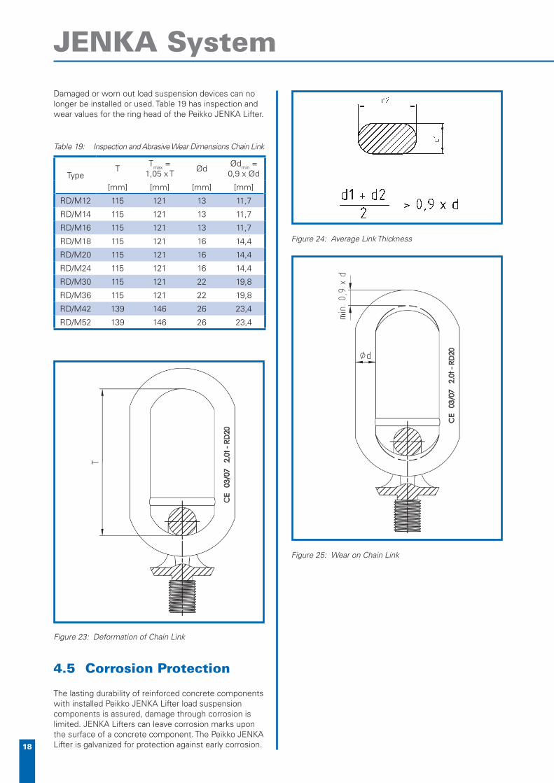
Deformation of the ring head (see fi gure 23)•
Reduction in ring width d• min at any location of more than 10% of width d (table 19)
Damage or heavy wear at the drop point (fi gure 25)•
Lengthening of nominal dimensions T beyond 5%.•
Figure 19: JENKA Lifter Installation for Lateral Pull
Figure 20: Incorrect loading
Figure 21: JENKA Lifter impermissable Angular Pull
Figure 22: JENKA Lifter Installation
Allowed
Not Allowed
Not Allowed
Directionnot allowed
18
JENKA System
Damaged or worn out load suspension devices can no longer be installed or used. Table 19 has inspection and wear values for the ring head of the Peikko JENKA Lifter.
Table 19: Inspection and Abrasive Wear Dimensions Chain Link
TypeT
Tmax = 1,05 x T
ØdØdmin = 0,9 x Ød
[mm] [mm] [mm] [mm]
RD/M12 115 121 13 11,7
RD/M14 115 121 13 11,7
RD/M16 115 121 13 11,7
RD/M18 115 121 16 14,4
RD/M20 115 121 16 14,4
RD/M24 115 121 16 14,4
RD/M30 115 121 22 19,8
RD/M36 115 121 22 19,8
RD/M42 139 146 26 23,4
RD/M52 139 146 26 23,4
4.5 Corrosion Protection
The lasting durability of reinforced concrete components with installed Peikko JENKA Lifter load suspension components is assured, damage through corrosion is limited. JENKA Lifters can leave corrosion marks upon the surface of a concrete component. The Peikko JENKA Lifter is galvanized for protection against early corrosion.
Figure 23: Deformation of Chain Link
Figure 24: Average Link Thickness
Figure 25: Wear on Chain Link

19
www.peikko.com
For your personal notes

Peikko Group • www.peikko.com