jd786a rfa ds cpo tm ae
TRANSCRIPT

8/12/2019 JD786A RFA Ds Cpo Tm Ae
http://slidepdf.com/reader/full/jd786a-rfa-ds-cpo-tm-ae 1/8
WEBSITE: www.jdsu.com/nse
NETWORK AND SERVICE ENABLEMENT
JD786ACellAdvisor™ RF Analyzer
Spectrum Analyzer: 9 kHz to 8 GHz
Cable and Antenna Analyzer: 5 MHz to 6 GHz
Power Meter: 10 MHz to 8 GHz
Specification* Conditions
Te JD786A specifications apply under these conditions:
• Te instrument has been turned on or at least 15 minutes
• Te instrument is operating within a valid calibration period
• Data with no tolerance are considered typical values
• Cable and antenna measurements apply afer calibration to the OSL standard
• ypical and nominal values are defined as: – ypical: expected perormance o the instrument operating under 20 to 30°C
afer being at this temperature or 15 minutes
– Nominal: a general, descriptive term or parameter
Spectrum Analyzer (Standard)
Frequency
Frequency range 9 kHz to 8 GHz
Internal 10 MHz Frequency Reference
Accuracy ±0.05 ppm + aging (0 to 50°C)
Aging ±0.5 ppm/year
Frequency Span
Range 0 Hz (zero span)
10 Hz to 8 GHz
Resolution 1 Hz
Resolution Bandwidth (RBW)
–3 dB bandwidth 1 Hz to 3 MHz 1-3-10 sequence
Accuracy ±10% (nominal)
Video Bandwidth (VBW)
–3 dB bandwidth 1 Hz to 3 MHz 1-3-10 sequence
Accuracy ±10% (nominal)
Single Sideband (SSB) Phase Noise
Fc 1 GHz, RBW 10 kHz, VBW 1 kHz, RMS detector
Carrier offset:
30 kHz100 kHz
1 MHz
–100 dBc/Hz ( –102 dBc/Hz, typical)–105 dBc/Hz ( –112 dBc/Hz, typical)
–115 dBc/Hz ( –120 dBc/Hz, typical)
Measurement Range
DANL to +25 dBm
Input attenuator range 0 to 55 dB, 5 dB steps
Maximum Input Level
Average continuous power +25 dBm
DC voltage ±50 V DC
Displayed Average Noise Level (DANL)
1 Hz RBW, 1 Hz VBW, 50 Ω termination, 0 dB attenuation, RMS detectorPreamplifier off:
10 MHz to 3 GHz
>3 GHz to 5 GHz
>5 GHz to 7 GHz
>7 GHz to 8 GHz
–140 dBm (–145 dBm, typical)
–138 dBm (–142 dBm, typical)
–135 dBm (–138 dBm, typical)
–132 dBm (–135 dBm, typical)
Preamplifier on:
10 MHz to 3 GHz
>3 GHz to 5 GHz
>5 GHz to 7 GHz
>7 GHz to 8 GHz
–160 dBm (–165 dBm, typical)
–158 dBm (–162 dBm, typical)
–155 dBm (–158 dBm, typical)
–152 dBm (–155 dBm, typical)
*All speciications are subject to change without notice.
8/12/2019 JD786A RFA Ds Cpo Tm Ae
http://slidepdf.com/reader/full/jd786a-rfa-ds-cpo-tm-ae 2/8
2
JD786A CELLADVISOR RF ANALYZER
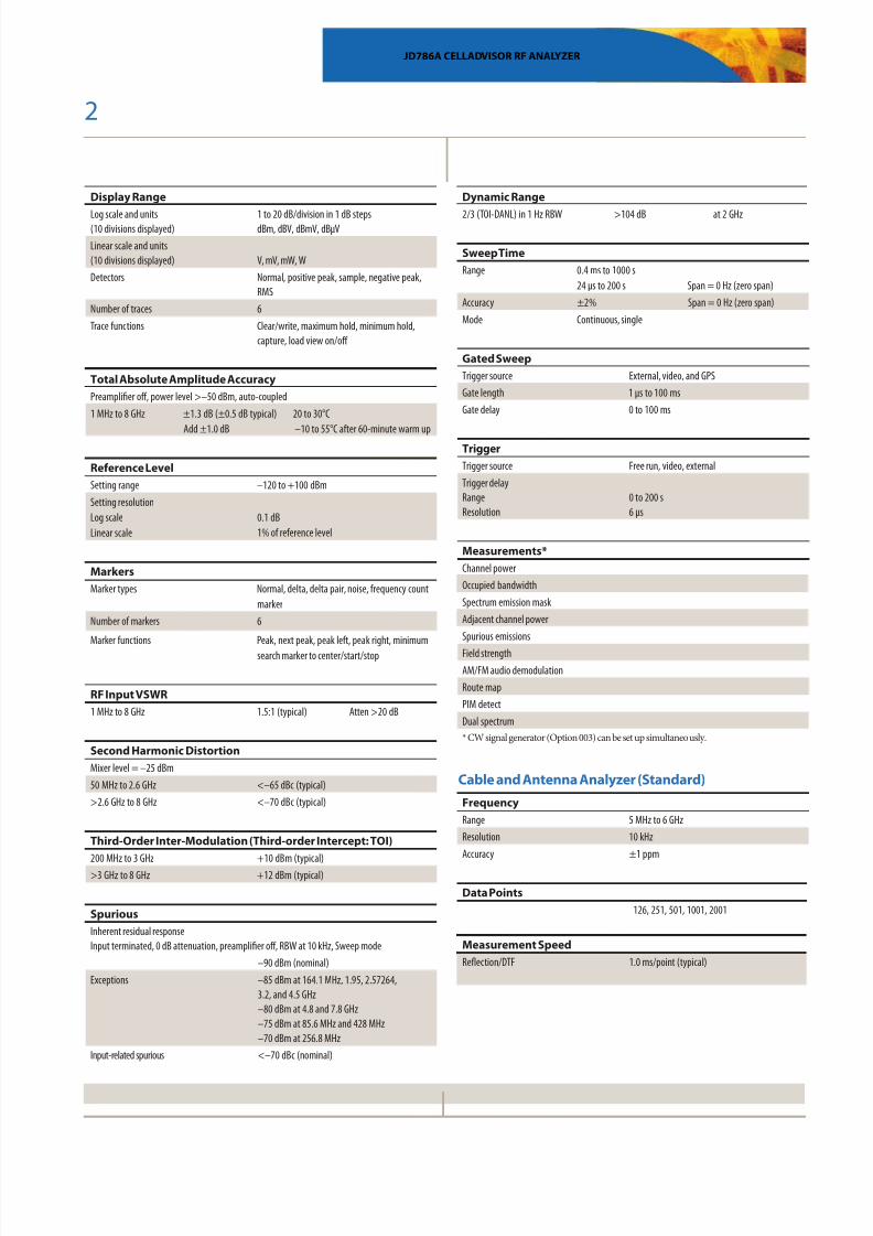
Display Range
Log scale and units(10 divisions displayed)
1 to 20 dB/division in 1 dB stepsdBm, dBV, dBmV, dBµV
Linear scale and units(10 divisions displayed)
V, mV, mW, W
Detectors Normal, positive peak, sample, negative peak,RMS
Number of traces 6
Trace functions Clear/write, maximum hold, minimum hold,capture, load view on/off
Total Absolute Amplitude Accuracy
Preamplifier off, power level >–50 dBm, auto-coupled
1 MHz to 8 GHz ±1.3 dB (±0.5 dB typical)
Add ±1.0 dB
20 to 30°C
–10 to 55°C after 60-minute warm up
Reference Level
Setting range –120 to +100 dBm
Setting resolution
Log scale
Linear scale
0.1 dB
1% of reference level
Markers
Marker types Normal, delta, delta pair, noise, frequency count
marker
Number of markers 6
Marker functions Peak, next peak, peak left, peak right, minimum
search marker to center/start/stop
RF Input VSWR
1 MHz to 8 GHz 1.5:1 (typical) Atten >20 dB
Second Harmonic Distortion
Mixer level = –25 dBm
50 MHz to 2.6 GHz <–65 dBc (typical)
>2.6 GHz to 8 GHz <–70 dBc (typical)
Third-Order Inter-Modulation (Third-order Intercept: TOI)
200 MHz to 3 GHz +10 dBm (typical)
>3 GHz to 8 GHz +12 dBm (typical)
Spurious
Inherent residual responseInput terminated, 0 dB attenuation, preamplifier off, RBW at 10 kHz, Sweep mode
–90 dBm (nominal)
Exceptions –85 dBm at 164.1 MHz, 1.95, 2.57264,3.2, and 4.5 GHz–80 dBm at 4.8 and 7.8 GHz–75 dBm at 85.6 MHz and 428 MHz–70 dBm at 256.8 MHz
Input-related spurious <–70 dBc (nominal)
Dynamic Range
2/3 (TOI-DANL) in 1 Hz RBW >104 dB at 2 GHz
Sweep Time
Range 0.4 ms to 1000 s
24 µs to 200 s
Span = 0 Hz (zero span)
Accuracy ±2% Span = 0 Hz (zero span)
Mode Continuous, single
Gated Sweep
Trigger source External, video, and GPS
Gate length 1 µs to 100 ms
Gate delay 0 to 100 ms
Trigger
Trigger source Free run, video, external
Trigger delayRangeResolution
0 to 200 s6 µs
Measurements*
Channel power
Occupied bandwidth
Spectrum emission mask
Adjacent channel power
Spurious emissions
Field strength
AM/FM audio demodulation
Route map
PIM detect
Dual spectrum
* CW signal generator (Option 003) can be set up simultaneously.
Cable and Antenna Analyzer (Standard)
Frequency
Range 5 MHz to 6 GHz
Resolution 10 kHz
Accuracy ±1 ppm
Data Points
126, 251, 501, 1001, 2001
Measurement Speed
Reflection/DTF 1.0 ms/point (typical)
8/12/2019 JD786A RFA Ds Cpo Tm Ae
http://slidepdf.com/reader/full/jd786a-rfa-ds-cpo-tm-ae 3/8
3
JD786A CELLADVISOR RF ANALYZER
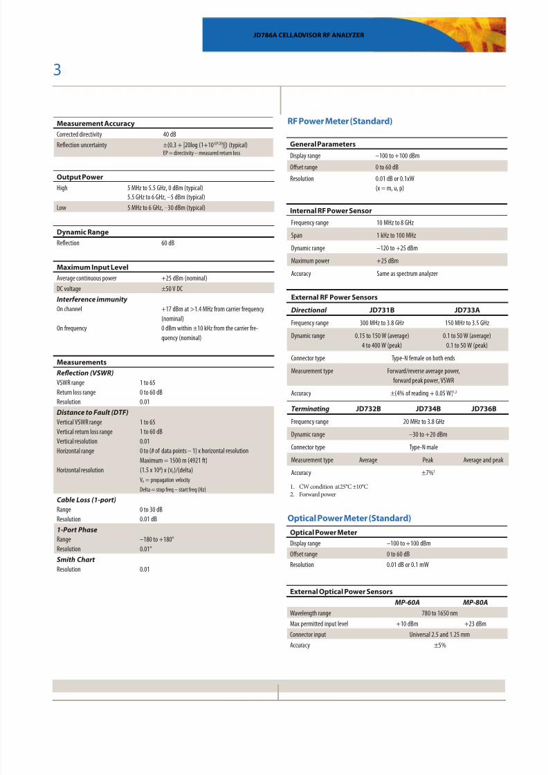
Measurement Accuracy
Corrected directivity 40 dBReflection uncertainty ±(0.3 + |20log (1+10-EP/20)|) (typical)
EP = directivity – measured return loss
Output Power
High 5 MHz to 5.5 GHz, 0 dBm (typical)5.5 GHz to 6 GHz, –5 dBm (typical)
Low 5 MHz to 6 GHz, –30 dBm (typical)
Dynamic Range
Reflection 60 dB
Maximum Input Level
Average continuous power +25 dBm (nominal)
DC voltage ±50 V DC
Interference immunity
On channel
On frequency
+17 dBm at >1.4 MHz from carrier frequency
(nominal)
0 dBm within ±10 kHz from the carrier fre-
quency (nominal)
Measurements
Reflection (VSWR)
VSWR range
Return loss range
Resolution
1 to 65
0 to 60 dB
0.01
Distance to Fault (DTF)
Vertical VSWR range
Vertical return loss range
Vertical resolution
Horizontal range
Horizontal resolution
1 to 65
1 to 60 dB
0.01
0 to (# of data points – 1) x horizontal resolution
Maximum = 1500 m (4921 ft)
(1.5 x 10⁸) x (VP)/(delta)
VP = propagation velocity
Delta = stop freq – start freq (Hz)
Cable Loss (1-port)
Range
Resolution
0 to 30 dB
0.01 dB
1-Port Phase
RangeResolution
–180 to +180°0.01°
Smith Chart
Resolution
0.01
RF Power Meter (Standard)
General Parameters
Display range –100 to +100 dBm
Offset range 0 to 60 dB
Resolution 0.01 dB or 0.1xW
(x = m, u, p)
Internal RF Power Sensor
Frequency range 10 MHz to 8 GHz
Span 1 kHz to 100 MHz
Dynamic range –120 to +25 dBm
Maximum power +25 dBm
Accuracy Same as spectrum analyzer
External RF Power Sensors
Directional JD731B JD733A
Frequency range 300 MHz to 3.8 GHz 150 MHz to 3.5 GHz
Dynamic range 0.15 to 150 W (average)
4 to 400 W (peak)
0.1 to 50 W (average)
0.1 to 50 W (peak)
Connector type Type-N female on both ends
Measurement type Forward/reverse average power,
forward peak power, VSWR
Accuracy ±(4% of reading + 0.05 W)1,2
Terminating JD732B JD734B JD736B
Frequency range 20 MHz to 3.8 GHz
Dynamic range –30 to +20 dBm
Connector type Type-N male
Measurement type Average Peak Average and peak
Accuracy ±7%1
1. CW condition at 25°C ±10°C2. Forward power
Optical Power Meter (Standard)
Optical Power Meter
Display range –100 to +100 dBmOffset range 0 to 60 dB
Resolution 0.01 dB or 0.1 mW
External Optical Power Sensors
MP-60A MP-80A
Wavelength range 780 to 1650 nm
Max permitted input level +10 dBm +23 dBm
Connector input Universal 2.5 and 1.25 mm
Accuracy ±5%
8/12/2019 JD786A RFA Ds Cpo Tm Ae
http://slidepdf.com/reader/full/jd786a-rfa-ds-cpo-tm-ae 4/8

8/12/2019 JD786A RFA Ds Cpo Tm Ae
http://slidepdf.com/reader/full/jd786a-rfa-ds-cpo-tm-ae 5/8

8/12/2019 JD786A RFA Ds Cpo Tm Ae
http://slidepdf.com/reader/full/jd786a-rfa-ds-cpo-tm-ae 6/8
6
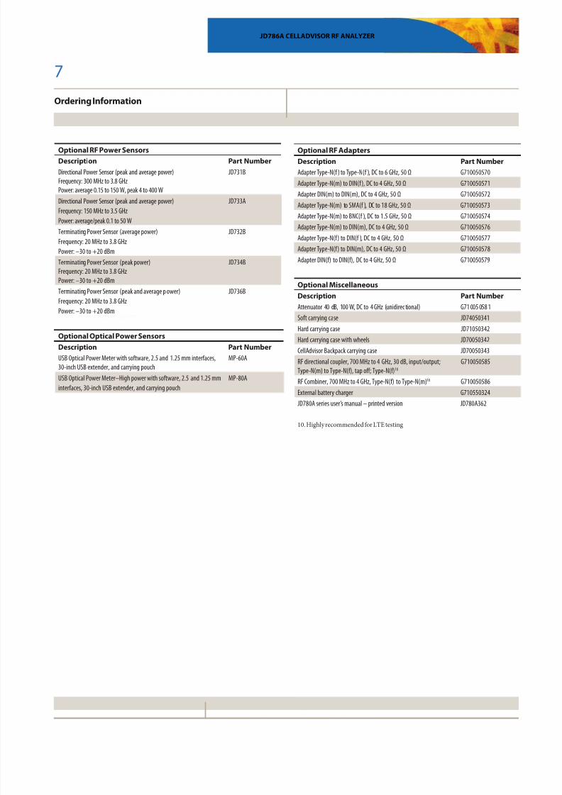
Ordering Information
JD786A CELLADVISOR RF ANALYZER
Optional RF Cables
Description Part Number
1.0 m (3.28 ft) RF cable, DC to 18 GHz, Type-N(m) to Type-N(m), 50 Ω G710050530
1.5 m (4.92 ft) RF cable, DC to 18 GHz, Type-N(m) to Type-N(f), 50 Ω G710050531
3.0 m (9.84 ft) RF cable, DC to 18 GHz, Type-N(m) to Type-N(f), 50 Ω G710050532
1.5 m (4.92 ft) RF cable, DC to 18 GHz, Type-N(m) to SMA(m), 50 Ω G710050533
1.5 m (4.92 ft) RF cable, DC to 18 GHz, Type-N(m) to QMA(m), 50 Ω G710050534
1.5 m (4.92 ft) RF cable, DC to 18 GHz, Type-N(m) to SMB(m), 50 Ω G710050535
Optional Omni Antennas
Description Part Number
RF omni antenna Type-N(m), 806 MHz to 896 MHz G700050353
RF omni antenna Type-N(m), 870 MHz to 960 MHz G700050354
RF omni antenna Type-N(m), 1.71 GHz to 2.17 GHz G700050355
RF omni antenna Type-N(m), 720 MHz to 800 MHz G700050356
RF omni antenna Type-N(m), 2.3 GHz to 2.7 GHz G700050357
Optional Yagi Antennas
Description Part Number
RF Yagi antenna Type-N(f), 806 MHz to 896 MHz, 10.2 dBd 8 G700050364
RF Yagi antenna Type-N(f), 866 MHz to 960 MHz, 10.2 dBd 8 G700050365
RF Yagi antenna Type-N(f), 1.75 GHz to 2.39 GHz, 9.8 dBd8 G700050363
RF Yagi antenna Type-SMA(f), 700 MHz to 4 GHz, 1 .85 dBd9 G700050366
1. Requires calibration kit2. Requires dual-port calibration kit
3. Requires Option 1
4. Includes a pair o Bluetooth USB dongles with 5 dBi dipole antenna
(JD70050006)
5. Highly recommend adding GPS receiver JD786A010
6. Highly recommend adding antennas G70005035x and/or G70005036x
7. Standard accessory that can be purchased separately
8. Require RF cables G710050530
9. Requires RF cables G710050533
Standard
Description Part Number
9 kHz to 8 GHz Spectrum analyzer5 MHz to 6 GHz Cable and antenna analyzer1
10 MHz to 8 GHz RF power meter (internal mode)
JD786A
Options
NOTE: Upgrade options for the JD786A use the designation JD786AU
before the respective last three-digit option number.
Description Part Number
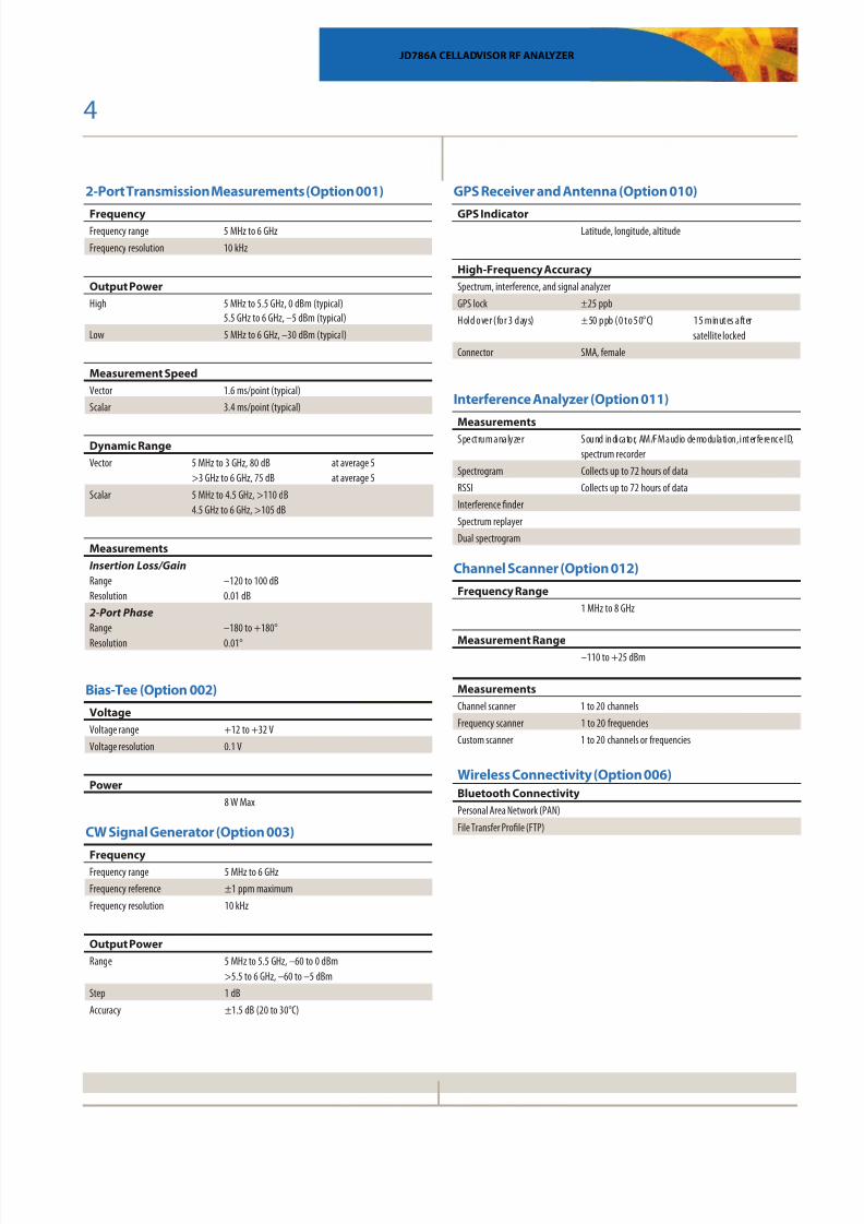
2-Port Transmission Measurement2 JD786A001
Bias-Tee3 JD786A002
CW Signal Generator JD786A003
Bluetooth Connectivity4 JD786A006
GPS Receiver and Antenna JD786A010
Interference Analyzer 5, 6 JD786A011
Channel Scanner JD786A012
Standard Accessories
Description Part Number
AC/DC power adapter7 G710550326
Cross LAN cable (1.5 m)7 G710550335
USB A to B cable (1.8 m)7 GC73050515
>1 GB USB memory7 GC72450518
Rechargeable lithium ion battery7 G710550325
Automotive cigarette lighter 12 V DC adapter7
G710550323Stylus7 G710550316
JD780A Series user’s manual and application software — CD JD780A361
Optional Calibration Kits
Description Part Number
Y-Calibration Kit, Type-N(m), DC to 6 GHz, 50 Ω JD78050509
Dual-port Type-N calibration kit, 50 Ω
• Y-calibration kit, Type-N(m), DC to 6 GHz, 50 Ω
• Two adapters Type-N(f) to Type-N(f), DC to 6 GHz, 50 Ω
• Two 1 m RF test cables, Type-N(m) to Type-N(m),
DC to 18 GHz, 50 Ω
JD78050507
8/12/2019 JD786A RFA Ds Cpo Tm Ae
http://slidepdf.com/reader/full/jd786a-rfa-ds-cpo-tm-ae 7/8
8/12/2019 JD786A RFA Ds Cpo Tm Ae
http://slidepdf.com/reader/full/jd786a-rfa-ds-cpo-tm-ae 8/8Product specifications anddescriptions in this document subject tochange without notice.©2013 JDSUniphase Corporation 30173455 003 1213 JD786ARFA.DS.CPO.TM.AE December 2013
JD786A CELLADVISOR RF ANALYZER
Network and Service Enablement Regional Sales
LATIN AMERICA
TEL: +1 954 688-5660
FAX: +1 954 3454668
ASIA PACIFIC
TEL:+852 2892 0990
FAX:+852 2892 0770
EMEA
TEL:+49 7121 86 2222
FAX:+49 7121 86 1222
www.jdsu.com/nseNORTH AMERICA
TOLL FREE: 1 855 ASK-JDSU
1 855 275-5378