jblm design standards section 22 00 00 - alutiiq, llc · jblm design standards section 22 00 00 ......
TRANSCRIPT

SECTION 22 00 00 Page 1
JBLM DESIGN STANDARDS SECTION 22 00 00 - PLUMBING, GENERAL PURPOSE Design Requirements
a. Water Heaters: Where used at facilities with showers, size peak demand for 100% shower use.
b. Isolation valves 2" and smaller shall be full port ball type; valves 2-1/2" and larger may be full port ball, butterfly, or gate type.
c. Faucets: Single lever type preferred. Use manufacturers that have a single cartridge style that fits entire product line (i.e. lavatories, kitchens, and showers). See 3.10, Section P-5.
d. Provide trap primer devices for all floor drains except those in dining areas and latrines in barracks
Notes to Designers on Drawing Content
1. The following information shall be shown on the project drawings: a. Configuration and sizes of piping systems. b. Locations of hot water and cold water shut-off valves for each toilet room. c. Location and type of each plumbing fixture. d. Typical details for attaching wall-hung fixtures to walls. e. Whether piping is run above or below ground, floors, and ceilings and whether
concealed or exposed. f. Capacity and efficiency of each item of equipment. g. Locations and details for special supports for piping. h. Locations, sizes, and types of cleanouts i. Locations, sizes, and typical details for extended rim floor drains. j. Detail sections through each roof drain, floor sink, and grease interceptor (trap). k. Location of acid-resistant DWV piping, cleanouts, traps, drains and accessories. l. Cleanouts in crawl spaces or exterior of buildings shall be not less than one meter
3 feet from building wall. m. Exterior buried piping shall not be run parallel to and 1.50 meters 5 feet from
Exterior building wall. n. Location and size of water hammer arresters or air chambers. o. Scale ranges for gages and thermometers. p. Capacity, size, by-pass valves, and piping for water meters and detail of water
meter box. q. Locations and sizes of access panels for valves. r. Details of pipe penetrations in outside walls. s. Locations of fire walls and fire floors. t. Location of wye strainer (with blow-off outlet, pipe nipple, and gate valve) in
water supply to each building.
2. Provide isolation valves so as to allow for maintenance of portions of system without having to shut down the entire building. Provide valves as a minimum as follows:
a. At each water hammer arrester. b. At each trap primer valve.

SECTION 22 00 00 Page 2
c. At each plumbing fixture group (2 or more fixtures). d. At each wing (and floor) of the building. e. At all equipment (pumps, water heaters, tanks, etc.). f. Provide ability to isolate hot water circulation piping. g. At all outside hose bibbs.
3. Provide a separate isolation valve in addition to balancing valves (balancing valves are not considered isolation valves). 4. Provide offset p-traps at handicap accessible lavatories. 5. Provide access panels (or doors) to allow access to bathtub overflow fittings. Locate Reduced Pressure Backflow Preventors (RPBP) to be readily accessible (between 3' and 5' above floor, with clear access path). Pipe with an air gap drain to floor drain. 6. Provide floor drains in restrooms that have more than 2 fixtures; locate at RPBP; locate adjacent to each piece of equipment in mechanical room having a relief valve, blow-down or similar discharge of water; locate drains between equipment and in as economical a manner as possible to reduce number of drains needed. 7. Combined horizontal venting shall be a minimum of 42" above finished floor grade. 8. Show full size assessable clean-outs on all waste and drain systems as follows:
a. On each floor of sewer and vent stack risers b. Indirect waste receptacles c. 12" above waste arm on vent system for automatic washer hookups. d. Two-way cleanout on building drain located within 2' of building.
SECTION 22 00 00
PLUMBING, GENERAL PURPOSE PART 1 GENERAL 1.1 REFERENCES The publications listed below form a part of this specification to the extent referenced. The publications are referred to within the text by the basic designation only.
AIR-CONDITIONING, HEATING AND REFRIGERATION INSTITUTE (AHRI)
ARI 1010 (2002) Self-Contained, Mechanically
Refrigerated Drinking-Water Coolers
AMERICAN SOCIETY OF HEATING, REFRIGERATING AND AIR-CONDITIONING ENGINEERS (ASHRAE)
SECTION 22 00 00 Page 3
ASHRAE 146 (2006) Method of Testing and Rating Pool Heaters
ASHRAE 90.1 - IP (2007) Energy Standard for Buildings Except
Low-Rise Residential Buildings, I-P Edition
AMERICAN SOCIETY OF SANITARY ENGINEERING (ASSE) ASSE 1001 (2008) Atmospheric Type Vacuum Breakers
ASSE 1003 (2001; Errata, 2003) Performance Requirements
for Water Pressure Reducing Valves ASSE 1005 (1999) Water Heater Drain Valves 3/4 Inch
Size ASSE 1010 (2004) Water Hammer Arresters
ASSE 1011 (2004; Errata 2004) Hose Connection Vacuum
Breakers ASSE 1012 (2002) Backflow Preventer with Intermediate
Atmospheric Vent ASSE 1013 (2005) Reduced Pressure Principle Backflow
Preventers and Reduced Pressure Fire Protection Principle Backflow Preventers
ASSE 1018 (2001) Trap Seal Primer Valves - Potable,
Water Supplied ASSE 1019 (2004; Errata 2005) Vacuum Breaker Wall
Hydrants, Freeze Resistant, Automatic Draining Type
ASSE 1020 (2004; Errata 2004; Errata 2004) Pressure
Vacuum Breaker Assembly
AMERICAN WATER WORKS ASSOCIATION (AWWA) AWWA 10084 (2005) Standard Methods for the Examination
of Water and Wastewater AWWA B300 (2004) Hypochlorites
AWWA B301 (2004) Liquid Chlorine
AWWA C203 (2002) Coal-Tar Protective Coatings and
Linings for Steel Water Pipelines - Enamel and Tape - Hot-Applied
AWWA C606 (2006) Grooved and Shouldered Joints
AWWA C651 (2005; Errata 2005) Standard for Disinfecting
Water Mains

SECTION 22 00 00 Page 4
AWWA C652 (2002) Disinfection of Water-Storage Facilities
AWWA C700 (2002; R 2003) Standard for Cold Water Meters
- Displacement Type, Bronze Main Case AWWA C701 (2007) Standard for Cold-Water Meters -
Turbine Type for Customer Service AWWA M14 (2004) Manual: Recommended Practice for
Backflow Prevention and Cross-Connection Control
AMERICAN WELDING SOCIETY (AWS)
AWS A5.8/A5.8M (2004; Errata 2004) Specification for Filler
Metals for Brazing and Braze Welding AWS B2.2 (1991) Brazing Procedure and Performance
Qualification
ASME INTERNATIONAL (ASME) ASME A112.1.2 (2004) Standard for Air Gaps in Plumbing
Systems (For Plumbing Fixtures and Water-Connected Receptors)
ASME A112.14.1 (2003) Backwater Valves
ASME A112.19.1M (1994; R 2004) Enameled Cast Iron Plumbing
Fixtures ASME A112.19.2M (2003) Standard for Vitreous China Plumbing
Fixtures and Hydraulic Requirements for Water Closets and Urinals
ASME A112.19.3 (2000: R 2004) Stainless Steel Plumbing
Fixtures (Designed for Residential Use) ASME A112.19.4M (1994; R 2004) Porcelain Enameled Formed
Steel Plumbing Fixtures ASME A112.19.5 (2005) Trim for Water-Closet Bowls, Tanks and
Urinals ASME A112.21.2M (1983) Roof Drains
ASME A112.36.2M (1991; R 2002) Cleanouts
ASME A112.6.1M (1997; R 2002) Floor Affixed Supports for
Off-the-Floor Plumbing Fixtures for Public Use
ASME A112.6.3 (2001; R 2007) Standard for Floor and Trench
Drains
SECTION 22 00 00 Page 5
ASME B1.20.1 (1983; R 2006) Pipe Threads, General Purpose (Inch)
ASME B16.12 (1998; R 2006) Cast Iron Threaded Drainage
Fittings ASME B16.15 (2006) Cast Bronze Threaded Fittings Classes
125 and 250 ASME B16.18 (2001; R 2005) Cast Copper Alloy Solder Joint
Pressure Fittings ASME B16.21 (2005) Nonmetallic Flat Gaskets for Pipe
Flanges ASME B16.22 (2001; R 2005) Standard for Wrought Copper
and Copper Alloy Solder Joint Pressure Fittings
ASME B16.23 (2002; Errata 2003; R 2006) Cast Copper Alloy
Solder Joint Drainage Fittings - DWV ASME B16.24 (2006) Cast Copper Alloy Pipe Flanges and
Flanged Fittings: Classes 150, 300, 400, 600, 900, 1500, and 2500
ASME B16.29 (2007) Wrought Copper and Wrought Copper
Alloy Solder Joint Drainage Fittings - DWV ASME B16.3 (2006) Malleable Iron Threaded Fittings,
Classes 150 and 300 ASME B16.34 (2004) Valves - Flanged, Threaded and Welding
End ASME B16.39 (1998; R 2006) Standard for Malleable Iron
Threaded Pipe Unions; Classes 150, 250, and 300
ASME B16.4 (2006) Standard for Gray Iron Threaded
Fittings; Classes 125 and 250 ASME B16.5 (2003) Standard for Pipe Flanges and Flanged
Fittings: NPS 1/2 Through NPS 24 ASME B31.1 (2007; Addenda 2008) Power Piping
ASME B31.5 (2006) Refrigeration Piping and Heat Transfer
Components ASME B40.100 (2006) Pressure Gauges and Gauge Attachments
ASME BPVC SEC IX (2007; Addenda 2008) Boiler and Pressure
Vessel Code; Section IX, Welding and Brazing Qualifications

SECTION 22 00 00 Page 6
ASME BPVC SEC VIII (2007; Addenda 2008) Boiler and Pressure Vessel Codes: Section VIII Rules for Construction of Pressure Vessels, Division 1
ASME BPVC SEC VIII D1 (2007; Addenda 2008) Boiler and Pressure
Vessel Code; Section VIII, Pressure Vessels Division 1 - Basic Coverage
ASME CSD-1 (2006) Control and Safety Devices for
Automatically Fired Boilers
ASTM INTERNATIONAL (ASTM) ASTM A 105/A 105M (2005) Standard Specification for Carbon
Steel Forgings for Piping Applications ASTM A 183 (2003) Standard Specification for Carbon
Steel Track Bolts and Nuts ASTM A 193/A 193M (2007) Standard Specification for Alloy-Steel
and Stainless Steel Bolting Materials for High-Temperature Service
ASTM A 47/A 47M (1999; R 2004) Standard Specification for
Steel Sheet, Aluminum-Coated, by the Hot-Dip Process
ASTM A 515/A 515M (2003; R 2007) Standard Specification for
Pressure Vessel Plates, Carbon Steel, for Intermediate- and Higher-Temperature Service
ASTM A 516/A 516M (2006) Standard Specification for Pressure
Vessel Plates, Carbon Steel, for Moderate- and Lower-Temperature Service
ASTM A 518/A 518M (1999; R 2003) Standard Specification for
Corrosion-Resistant High-Silicon Iron Castings
ASTM A 53/A 53M (2007) Standard Specification for Pipe,
Steel, Black and Hot-Dipped, Zinc-Coated, Welded and Seamless
ASTM A 536 (1984; R 2004) Standard Specification for
Ductile Iron Castings ASTM A 733 (2003) Standard Specification for Welded and
Seamless Carbon Steel and Austenitic Stainless Steel Pipe Nipples
ASTM A 74 (2006) Standard Specification for Cast Iron
Soil Pipe and Fittings ASTM A 888 (2007a) Standard Specification for Hubless
Cast Iron Soil Pipe and Fittings for Sanitary and Storm Drain, Waste, and Vent Piping Applications

SECTION 22 00 00 Page 7
ASTM B 111/B 111M (2004) Standard Specification for Copper and
Copper-Alloy Seamless Condenser Tubes and Ferrule Stock
ASTM B 117 (2007a) Standing Practice for Operating Salt
Spray (Fog) Apparatus ASTM B 152/B 152M (2006ae1) Standard Specification for Copper
Sheet, Strip, Plate, and Rolled Bar ASTM B 306 (2002) Standard Specification for Copper
Drainage Tube (DWV) ASTM B 32 (2004) Standard Specification for Solder
Metal ASTM B 370 (2003) Standard Specification for Copper
Sheet and Strip for Building Construction ASTM B 42 (2002e1) Standard Specification for Seamless
Copper Pipe, Standard Sizes ASTM B 43 (1998; R 2004) Standard Specification for
Seamless Red Brass Pipe, Standard Sizes ASTM B 584 (2006a) Standard Specification for Copper
Alloy Sand Castings for General Applications ASTM B 75 (2002) Standard Specification for Seamless
Copper Tube ASTM B 813 (2000e1) Standard Specification for Liquid
and Paste Fluxes for Soldering of Copper and Copper Alloy Tube
ASTM B 828 (2002) Standard Practice for Making Capillary
Joints by Soldering of Copper and Copper Alloy Tube and Fittings
ASTM B 88 (2003) Standard Specification for Seamless
Copper Water Tube ASTM B 88M (2005) Standard Specification for Seamless
Copper Water Tube (Metric) ASTM C 1053 (2000; R 2005) Standard Specification for
Borosilicate Glass Pipe and Fittings for Drain, Waste, and Vent (DWV) Applications
ASTM C 564 (2003a) Standard Specification for Rubber
Gaskets for Cast Iron Soil Pipe and Fittings ASTM C 920 (2008) Standard Specification for Elastomeric
Joint Sealants

SECTION 22 00 00 Page 8
ASTM D 1004 (2007) Initial Tear Resistance of Plastic Film and Sheeting
ASTM D 1248 (2005) Standard Specification for
Polyethylene Plastics Extrusion Materials for Wire and Cable
ASTM D 1785 (2006) Standard Specification for Poly(Vinyl
Chloride) (PVC), Plastic Pipe, Schedules 40, 80, and 120
ASTM D 2000 (2008) Standard Classification System for
Rubber Products in Automotive Applications ASTM D 2235 (2004) Standard Specification for Solvent
Cement for Acrylonitrile-Butadiene-Styrene (ABS) Plastic Pipe and Fittings
ASTM D 2239 (2003) Standard Specification for
Polyethylene (PE) Plastic Pipe (SIDR-PR) Based on Controlled Inside Diameter
ASTM D 2241 (2005) Standard Specification for Poly(Vinyl
Chloride) (PVC) Pressure-Rated Pipe (SDR Series)
ASTM D 2447 (2003) Standard Specification for
Polyethylene (PE) Plastic Pipe, Schedules 40 and 80, Based on Outside Diameter
ASTM D 2464 (2006) Standard Specification for Threaded
Poly(Vinyl Chloride) (PVC) Plastic Pipe Fittings, Schedule 80
ASTM D 2466 (2006) Standard Specification for Poly(Vinyl
Chloride) (PVC) Plastic Pipe Fittings, Schedule 40
ASTM D 2467 (2006) Standard Specification for Poly(Vinyl
Chloride) (PVC) Plastic Pipe Fittings, Schedule 80
ASTM D 2485 (1991; R 2007) Evaluating Coatings for High
Temperature Service ASTM D 2564 (2004e1) Standard Specification for Solvent
Cements for Poly(Vinyl Chloride) (PVC) Plastic Piping Systems
ASTM D 2657 (2007) Heat Fusion Joining Polyolefin Pipe
and Fittings ASTM D 2661 (2006) Standard Specification for
Acrylonitrile-Butadiene-Styrene (ABS) Schedule 40, Plastic Drain, Waste, and Vent Pipe and Fittings

SECTION 22 00 00 Page 9
ASTM D 2665 (2007) Standard Specification for Poly(Vinyl Chloride) (PVC) Plastic Drain, Waste, and Vent Pipe and Fittings
ASTM D 2672 (1996a; R 2003) Joints for IPS PVC Pipe Using
Solvent Cement ASTM D 2683 (2004) Standard Specification for Socket-Type
Polyethylene Fittings for Outside Diameter-Controlled Polyethylene Pipe and Tubing
ASTM D 2737 (2003) Polyethylene (PE) Plastic Tubing
ASTM D 2822 (2005) Asphalt Roof Cement
ASTM D 2846/D 2846M (2006) Chlorinated Poly(Vinyl Chloride)
(CPVC) Plastic Hot- and Cold-Water Distribution Systems
ASTM D 2855 (1996; R 2002) Standard Practice for Making
Solvent-Cemented Joints with Poly(Vinyl Chloride) (PVC) Pipe and Fittings
ASTM D 2996 (2001; R 2007e1) Filament-Wound "Fiberglass"
(Glass-Fiber-Reinforced Thermosetting-Resin) Pipe
ASTM D 3035 (2008) Polyethylene (PE) Plastic Pipe (DR-PR)
Based on Controlled Outside Diameter ASTM D 3122 (1995; R 2002) Solvent Cements for Styrene-
Rubber (SR) Plastic Pipe and Fittings ASTM D 3138 (2004) Solvent Cements for Transition Joints
Between Acrylonitrile-Butadiene-Styrene (ABS) and Poly(Vinyl Chloride) (PVC) Non-Pressure Piping Components
ASTM D 3139 (1998; R 2005) Joints for Plastic Pressure
Pipes Using Flexible Elastomeric Seals ASTM D 3212 (2007) Standard Specification for Joints for
Drain and Sewer Plastic Pipes Using Flexible Elastomeric Seals
ASTM D 3261 (2003) Standard Specification for Butt Heat
Fusion Polyethylene (PE) Plastic Fittings for Polyethylene (PE) Plastic Pipe and Tubing
ASTM D 3311 (2006a) Drain, Waste, and Vent (DWV) Plastic
Fittings Patterns ASTM D 4060 (2007) Abrasion Resistance of Organic
Coatings by the Taber Abraser

SECTION 22 00 00 Page 10
ASTM D 4101 (2007) Standard Specification for Polypropylene Injection and Extrusion Materials
ASTM D 4551 (1996e1; R 2008) Poly(Vinyl Chloride) (PVC)
Plastic Flexible Concealed Water-Containment Membrane
ASTM D 638 (2003) Standard Test Method for Tensile
Properties of Plastics ASTM E 1 (2007) Standard Specification for ASTM
Liquid-in-Glass Thermometers ASTM E 2129 (2005) Standard Practice for Data Collection
for Sustainability Assessment of Building Products
ASTM E 96/E 96M (2005) Standard Test Methods for Water Vapor
Transmission of Materials ASTM F 1290 (1998a; R 2004) Electrofusion Joining
Polyolefin Pipe and Fittings ASTM F 1760 (2001; R 2005e1) Coextruded Poly(Vinyl
Chloride) (PVC) Non-Pressure Plastic Pipe Having Reprocessed-Recycled Content
ASTM F 409 (2002) Thermoplastic Accessible and
Replaceable Plastic Tube and Tubular Fittings ASTM F 437 (2006) Standard Specification for Threaded
Chlorinated Poly(Vinyl Chloride) (CPVC) Plastic Pipe Fittings, Schedule 80
ASTM F 438 (2004) Standard Specification for Socket-Type
Chlorinated Poly(Vinyl Chloride) (CPVC) Plastic Pipe Fittings, Schedule 40
ASTM F 439 (2006) Standard Specification for Chlorinated
Poly(Vinyl Chloride) (CPVC) Plastic Pipe Fittings, Schedule 80
ASTM F 441/F 441M (2002) Standard Specification for Chlorinated
Poly(Vinyl Chloride) (CPVC) Plastic Pipe, Schedules 40 and 80
ASTM F 442/F 442M (1999; R 2005) Standard Specification for
Chlorinated Poly(Vinyl Chloride) (CPVC) Plastic Pipe (SDR-PR)
ASTM F 477 (2007) Standard Specification for Elastomeric
Seals (Gaskets) for Joining Plastic Pipe ASTM F 493 (2004) Solvent Cements for Chlorinated
Poly(Vinyl Chloride) (CPVC) Plastic Pipe and Fittings

SECTION 22 00 00 Page 11
ASTM F 628 (2006e1) Acrylonitrile-Butadiene-Styrene
(ABS) Schedule 40 Plastic Drain, Waste, and Vent Pipe with a Cellular Core
ASTM F 877 (2007) Crosslinked Polyethylene (PEX) Plastic
Hot- and Cold- Water Distribution Systems ASTM F 891 (2007) Coextruded Poly (Vinyl Chloride) (PVC)
Plastic Pipe with a Cellular Core
CAST IRON SOIL PIPE INSTITUTE (CISPI) CISPI 301 (2004) Hubless Cast Iron Soil Pipe and
Fittings for Sanitary and Storm Drain, Waste, and Vent Piping Applications
CISPI 310 (2004) Coupling for Use in Connection with
Hubless Cast Iron Soil Pipe and Fittings for Sanitary and Storm Drain, Waste, and Vent Piping Applications
COPPER DEVELOPMENT ASSOCIATION (CDA)
CDA A4015 (1994; R 1995) Copper Tube Handbook
CSA AMERICA, INC. (CSA/AM)
CSA/AM Z21.10.1 (2004; E 2005; A 2006, 2006) Gas Water
Heaters Vol. I, Storage Water Heaters with Input Ratings of 75,000 Btu Per Hour or Less
CSA/AM Z21.10.3 (2004; Addenda A 2007) Gas Water Heaters
Vol.III, Storage Water Heaters With Input Ratings Above 75,000 Btu Per Hour, Circulating and Instantaneous
CSA/AM Z21.22 (1999; R 2004; A 2000, 2001; R 2004) Relief
Valves for Hot Water Supply Systems
FOUNDATION FOR CROSS-CONNECTION CONTROL AND HYDRAULIC RESEARCH (FCCCHR)
FCCCHR Manual (1988e9) Manual of Cross-Connection Control
INTERNATIONAL ASSOCIATION OF PLUMBING AND MECHANICAL OFFICIALS (IAPMO)
UPC (2003) Uniform Plumbing Code
INTERNATIONAL CODE COUNCIL (ICC)
ICC A117.1 (2003; R 2004) Standard for Accessible and
Usable Buildings and Facilities ICC IPC (2006; Supplement 2007) International
Plumbing Code

SECTION 22 00 00 Page 12
INTERNATIONAL SAFETY EQUIPMENT ASSOCIATION (ISEA)
ISEA Z358.1 (2004) Emergency Eyewash and Shower Equipment
MANUFACTURERS STANDARDIZATION SOCIETY OF THE VALVE AND FITTINGS INDUSTRY (MSS)
MSS SP-110 (1996) Ball Valves Threaded, Socket-Welding,
Solder Joint, Grooved and Flared Ends MSS SP-25 (1998) Standard Marking System for Valves,
Fittings, Flanges and Unions MSS SP-44 (2006) Steel Pipeline Flanges
MSS SP-58 (2002) Standard for Pipe Hangers and Supports
- Materials, Design and Manufacture MSS SP-67 (2002a; R 2004) Standard for Butterfly Valves
MSS SP-69 (2003; R 2004) Standard for Pipe Hangers and
Supports - Selection and Application MSS SP-70 (2006) Standard for Cast Iron Gate Valves,
Flanged and Threaded Ends MSS SP-71 (2005) Standard for Gray Iron Swing Check
Valves, Flanged and Threaded Ends MSS SP-72 (1999) Standard for Ball Valves with Flanged
or Butt-Welding Ends for General Service MSS SP-73 (2003) Brazing Joints for Copper and Copper
Alloy Pressure Fittings MSS SP-78 (2005a) Cast Iron Plug Valves, Flanged and
Threaded Ends MSS SP-80 (2003) Bronze Gate, Globe, Angle and Check
Valves MSS SP-83 (2006) Standard for Class 3000 Steel Pipe
Unions Socket Welding and Threaded MSS SP-85 (2002) Standard for Cast Iron Globe & Angle
Valves, Flanged and Threaded Ends
NACE INTERNATIONAL (NACE) NACE SP0169 (2007) Control of External Corrosion on
Underground or Submerged Metallic Piping Systems
NATIONAL ELECTRICAL MANUFACTURERS ASSOCIATION (NEMA)

SECTION 22 00 00 Page 13
NEMA 250 (2003) Enclosures for Electrical Equipment (1000 Volts Maximum)
NEMA MG 1 (2007; Errata 2008) Standard for Motors and
Generators
NATIONAL FIRE PROTECTION ASSOCIATION (NFPA) NFPA 31 (2006; Errata 2006; Errata 2007) Installation
of Oil Burning Equipment NFPA 54 (2006) National Fuel Gas Code
NFPA 90A (2008) Standard for the Installation of Air
Conditioning and Ventilating Systems
NSF INTERNATIONAL (NSF) NSF 14 (2007; Addenda 2007) Plastics Piping System
Components and Related Materials NSF 61 (2007a) Drinking Water System Components -
Health Effects
PLASTIC PIPE AND FITTINGS ASSOCIATION (PPFA) PPFA-01 (1998) Plastic Pipe in Fire Resistive
Construction
PLUMBING AND DRAINAGE INSTITUTE (PDI) PDI G 101 (1996) Testing and Rating Procedure for
Grease Interceptors with Appendix of Sizing and Installation Data
PDI WH 201 (2006) Water Hammer Arresters Standard
SOCIETY OF AUTOMOTIVE ENGINEERS INTERNATIONAL (SAE)
SAE J1508 (1997) Hose Clamp Specifications
THE SOCIETY FOR PROTECTIVE COATINGS (SSPC)
SSPC SP 5 (2007) White Metal Blast Cleaning
U.S. ENVIRONMENTAL PROTECTION AGENCY (EPA)
Energy Star (1992; R 2006) Energy Star Energy Efficiency
Labeling System PL 93-523 (1974; A 1999) Safe Drinking Water Act
U.S. NATIONAL ARCHIVES AND RECORDS ADMINISTRATION (NARA)
10 CFR 430 Energy Conservation Program for Consumer
Products

SECTION 22 00 00 Page 14
21 CFR 175 Indirect Food Additives: Adhesives and Components of Coatings
40 CFR 50.12 National Primary and Secondary Ambient Air
Quality Standards for Lead PL 109-58 Energy Policy Act of 2005 (EPAct05)
UNDERWRITERS LABORATORIES (UL)
UL 174 (2004; Rev thru May 2006) Household Electric
Storage Tank Water Heaters UL 430 (2004; Rev thru Nov 2007) Waste Disposers
UL 499 (2005; Rev thru Mar 2008) Electric Heating
Appliances UL 732 (1995; Rev thru Feb 2005) Oil-Fired Storage
Tank Water Heaters
WASHINGTON STATE ADMINISTRATIVE CODE (WAC) 246-290-490 Cross Connection Control Manual 1.2 SUBMITTALS Government approval is required for submittals with a "G" designation; submittals not having a "G" designation are for information only or as otherwise designated. When used, a designation following the "G" designation identifies the office that will review the submittal for the Government. The following shall be submitted in accordance with Section 01 33 00 SUBMITTAL PROCEDURES:
SD-02 Shop Drawings
Plumbing System; G
Detail drawings consisting of schedules, performance charts, instructions, diagrams, and other information to illustrate the requirements and operations of systems that are not covered by the Plumbing Code.. Detail drawings for the complete plumbing system including piping layouts and locations of connections; dimensions for roughing-in, foundation, and support points; schematic diagrams and wiring diagrams or connection and interconnection diagrams. Detail drawings shall indicate clearances required for maintenance and operation. Where piping and equipment are to be supported other than as indicated, details shall include loadings and proposed support methods. Mechanical drawing plans, elevations, views, and details, shall be drawn to scale.
SD-03 Product Data
Local/Regional Materials

SECTION 22 00 00 Page 15
Documentation indicating distance between manufacturing facility and the project site. Indicate distance of raw material origin from the project site. Indicate relative dollar value of local/regional materials to total dollar value of products included in project.
Pipe Sleeves Submit manufacturer documentation indicating type of recovered materials and the percentage of such material the is (1) recovered and (2) postconsumer recycled content. Alternativly submit written justification of non-use per Section 01 62 35 RECYCLED/RECOVERED MATERIALS.
Environmental Data
Materials
Documentation indicating percentage of post-industrial and post-consumer recycled content per unit of product. Indicate relative dollar value of recycled content products to total dollar value of products included in project.
Fixtures
List of installed fixtures with manufacturer, model, and flow rate.
Flush valve water closets Flush valve urinals Flush tank water closets Wall hung lavatories Include faucets and flow rates.
Countertop lavatories Include faucets and flow rates.
Kitchen sinks Include faucets and flow rates.
Service sinks Include faucets and flow rates.
Drinking-water coolers; G Water heaters; G For Energy Star or FEMP qualified water heaters, submit manufacturer documentation demonstrating that the included model in Energy Star labeled or meets current FEMP efficiency requirements.
Pumps; G Backflow prevention assemblies; G Shower Faucets; G

SECTION 22 00 00 Page 16
Motors General-Purpose, Single-Speed, Polyphase Induction Motors. Submit manufacturer documentation demonstrating that the motor meets the premium effciency rating requirements in accordance with NEMA MG 1.
Welding
A copy of qualified procedures and a list of names and identification symbols of qualified welders and welding operators.
Vibration-Absorbing Features; G
Details of vibration-absorbing features, including arrangement, foundation plan, dimensions and specifications.
Plumbing System
Diagrams, instructions, and other sheets proposed for posting. Manufacturer's recommendations for the installation of bell and spigot and hubless joints for cast iron soil pipe.
SD-06 Test Reports
Tests, Flushing and Disinfection
Test reports in booklet form showing all field tests performed to adjust each component and all field tests performed to prove compliance with the specified performance criteria, completion and testing of the installed system. Each test report shall indicate the final position of controls.
Test of Backflow Prevention Assemblies; G
Certification of proper operation shall be as accomplished in accordance with state regulations by an individual certified by the state to perform such tests. If no state requirement exists, the Contractor shall have the manufacturer's representative test the device, to ensure the unit is properly installed and performing as intended. The Contractor shall provide written documentation of the tests performed and signed by the individual performing the tests.
SD-07 Certificates
Materials and Equipment
Where equipment is specified to conform to requirements of the
ASME Boiler and Pressure Vessel Code, the design, fabrication, and installation shall conform to the code.
Bolts
Written certification by the bolt manufacturer that the bolts furnished comply with the specified requirements.
SD-10 Operation and Maintenance Data

SECTION 22 00 00 Page 17
Plumbing System; G
Submit in accordance with Section 01 78 23 OPERATION AND MAINTENANCE DATA.
1.3 STANDARD PRODUCTS Specified materials and equipment shall be standard products of a manufacturer regularly engaged in the manufacture of such products. Specified equipment shall essentially duplicate equipment that has performed satisfactorily at least two years prior to bid opening. Standard products shall have been in satisfactory commercial or industrial use for 2 years prior to bid opening. The 2-year use shall include applications of equipment and materials under similar circumstances and of similar size. The product shall have been for sale on the commercial market through advertisements, manufacturers' catalogs, or brochures during the 2 year period.
1.3.1 Alternative Qualifications Products having less than a two-year field service record will be acceptable if a certified record of satisfactory field operation for not less than 6000 hours, exclusive of the manufacturer's factory or laboratory tests, can be shown.
1.3.2 Service Support The equipment items shall be supported by service organizations. Submit a certified list of qualified permanent service organizations for support of the equipment which includes their addresses and qualifications. These service organizations shall be reasonably convenient to the equipment installation and able to render satisfactory service to the equipment on a regular and emergency basis during the warranty period of the contract.
1.3.3 Manufacturer's Nameplate Each item of equipment shall have a nameplate bearing the manufacturer's name, address, model number, and serial number securely affixed in a conspicuous place; the nameplate of the distributing agent will not be acceptable.
1.3.4 Modification of References In each of the publications referred to herein, consider the advisory provisions to be mandatory, as though the word, "shall" had been substituted for "should" wherever it appears. Interpret references in these publications to the "authority having jurisdiction", or words of similar meaning, to mean the Contracting Officer.
1.3.4.1 Definitions For the International Code Council (ICC) Codes referenced in the contract documents, advisory provisions shall be considered mandatory, the word "should" shall be interpreted as "shall." Reference to the "code official" shall be interpreted to mean the "Contracting Officer." For Navy owned property, references to the "owner" shall be interpreted to mean the

SECTION 22 00 00 Page 18
"Contracting Officer." For leased facilities, references to the "owner" shall be interpreted to mean the "lessor." References to the "permit holder" shall be interpreted to mean the "Contractor."
1.3.4.2 Administrative Interpretations For ICC Codes referenced in the contract documents, the provisions of Chapter 1, "Administrator," do not apply. These administrative requirements are covered by the applicable Federal Acquisition Regulations (FAR) included in this contract and by the authority granted to the Officer in Charge of Construction to administer the construction of this project. References in the ICC Codes to sections of Chapter 1, shall be applied appropriately by the Contracting Officer as authorized by his administrative cognizance and the FAR.
1.4 DELIVERY, STORAGE, AND HANDLING Handle, store, and protect equipment and materials to prevent damage before and during installation in accordance with the manufacturer's recommendations, and as approved by the Contracting Officer. Replace damaged or defective items.
1.5 PERFORMANCE REQUIREMENTS 1.5.1 Welding Piping shall be welded in accordance with qualified procedures using performance-qualified welders and welding operators. Procedures and welders shall be qualified in accordance with ASME BPVC SEC IX. Welding procedures qualified by others, and welders and welding operators qualified by another employer, may be accepted as permitted by ASME B31.1. The Contracting Officer shall be notified 24 hours in advance of tests, and the tests shall be performed at the work site if practicable. Welders or welding operators shall apply their assigned symbols near each weld they make as a permanent record. Structural members shall be welded in accordance with Section 05 05 23 WELDING, STRUCTURAL.
1.5.2 Cathodic Protection and Pipe Joint Bonding Cathodic protection and pipe joint bonding systems shall be in accordance with Section 26 42 14.00 10 CATHODIC PROTECTION SYSTEM (SACRIFICIAL ANODE) and Section 26 42 17.00 10 CATHODIC PROTECTION SYSTEM (IMPRESSED CURRENT).
1.6 REGULATORY REQUIREMENTS Unless otherwise required herein, plumbing work shall be in accordance with ICC IPC. Energy consuming products and systems shall be in accordance with PL 109-58 and ASHRAE 90.1 - IP
1.7 PROJECT/SITE CONDITIONS The Contractor shall become familiar with details of the work, verify dimensions in the field, and advise the Contracting Officer of any discrepancy before performing any work.
1.8 INSTRUCTION TO GOVERNMENT PERSONNEL

SECTION 22 00 00 Page 19
When specified in other sections, furnish the services of competent instructors to give full instruction to the designated Government personnel in the adjustment, operation, and maintenance, including pertinent safety requirements, of the specified equipment or system. Instructors shall be thoroughly familiar with all parts of the installation and shall be trained in operating theory as well as practical operation and maintenance work.
Instruction shall be given during the first regular work week after the equipment or system has been accepted and turned over to the Government for regular operation. The number of man-days (8 hours per day) of instruction furnished shall be as specified in the individual section. When more than 4 man-days of instruction are specified, use approximately half of the time for classroom instruction. Use other time for instruction with the equipment or system.
When significant changes or modifications in the equipment or system are made under the terms of the contract, provide additional instruction to acquaint the operating personnel with the changes or modifications.
1.9 ACCESSIBILITY OF EQUIPMENT Install all work so that parts requiring periodic inspection, operation, maintenance, and repair are readily accessible. Install concealed valves, expansion joints, controls, dampers, and equipment requiring access, in locations freely accessible through access doors.
1.10 SUSTAINABLE DESIGN REQUIREMENTS 1.10.1 Local/Regional Materials Use materials or products extracted, harvested, or recovered, as well as manufactured, within a 500 mile radius from the project site, if available from a minimum of three sources.
1.10.2 Environmental Data Submit Table 1 of ASTM E 2129 for products listed in the Delivery Order.
PART 2 PRODUCTS 2.1 MATERIALS Materials for various services shall be in accordance with TABLES I and II. Pipe schedules shall be selected based on service requirements. Pipe fittings shall be compatible with the applicable pipe materials. Plastic pipe, fittings, and solvent cement shall meet NSF 14 and shall be NSF listed for the service intended. Plastic pipe, fittings, and solvent cement used for potable hot and cold water service shall bear the NSF seal "NSF-PW." Polypropylene pipe and fittings shall conform to dimensional requirements of Schedule 40, Iron Pipe size. Pipe threads (except dry seal) shall conform to ASME B1.20.1. Grooved pipe couplings and fittings shall be from the same manufacturer. Material or equipment containing lead shall not be used in any potable water system. In line devices such as water meters, building valves, check valves, meter stops, valves, fittings and back flow preventers shall comply with PL 93-523 and NSF 61, Section 8. End point devices such as drinking water fountains, lavatory faucets, kitchen and bar faucets, residential ice makers, supply stops and end point control valves used to
SECTION 22 00 00 Page 20
dispense water for drinking must meet the requirements of NSF 61, Section 9. Hubless cast-iron soil pipe shall not be installed underground, under concrete floor slabs, or in crawl spaces below kitchen floors. Plastic pipe shall not be installed in air plenums. Plastic pipe shall not be installed in a pressure piping system in buildings greater than three stories including any basement levels.
2.1.1 Pipe Joint Materials Grooved pipe and hubless cast-iron soil pipe shall not be used under ground. Solder containing lead shall not be used with copper pipe. Cast iron soil pipe and fittings shall be marked with the collective trademark of the Cast Iron Soil Institute. Joints and gasket materials shall conform to the following:
a. Coupling for Cast-Iron Pipe: for hub and spigot type ASTM A 74,
AWWA C606. For hubless type: CISPI 310
b. Coupling for Steel Pipe: AWWA C606.
c. Couplings for Grooved Pipe: Ductile Iron ASTM A 536 (Grade 65-45-12) or Malleable Iron ASTM A 47/A 47M, Grade 32510 or Copper ASTM A 536.
d. Flange Gaskets: Gaskets shall be made of non-asbestos material in
accordance with ASME B16.21. Gaskets shall be flat, 1/16 inch thick, and contain Aramid fibers bonded with Styrene Butadiene Rubber (SBR) or Nitro Butadiene Rubber (NBR). Gaskets shall be the full face or self centering flat ring type. Gaskets used for hydrocarbon service shall be bonded with NBR.
e. Brazing Material: Brazing material shall conform to AWS
A5.8/A5.8M, BCuP-5.
f. Brazing Flux: Flux shall be in paste or liquid form appropriate for use with brazing material. Flux shall be as follows: lead-free; have a 100 percent flushable residue; contain slightly acidic reagents; contain potassium borides; and contain fluorides.
g. Solder Material: Solder metal shall conform to ASTM B 32.
h. Solder Flux: Flux shall be liquid form, non-corrosive, and conform
to ASTM B 813, Standard Test 1.
i. PTFE Tape: PTFE Tape, for use with Threaded Metal or Plastic Pipe.
j. Rubber Gaskets for Cast-Iron Soil-Pipe and Fittings (hub and spigot type and hubless type): ASTM C 564.
k. Rubber Gaskets for Grooved Pipe: ASTM D 2000, maximum temperature
230 degrees F.
l. Flexible Elastomeric Seals: ASTM D 3139, ASTM D 3212 or ASTM F 477.
m. Bolts and Nuts for Grooved Pipe Couplings: Heat-treated carbon
steel, ASTM A 183.

SECTION 22 00 00 Page 21
n. Solvent Cement for Transition Joints between ABS and PVC
Nonpressure Piping Components: ASTM D 3138.
o. Plastic Solvent Cement for ABS Plastic Pipe: ASTM D 2235.
p. Plastic Solvent Cement for PVC Plastic Pipe: ASTM D 2564 and ASTM D 2855.
q. Plastic Solvent Cement for CPVC Plastic Pipe: ASTM F 493.
r. Flanged fittings including flanges, bolts, nuts, bolt patterns,
etc., shall be in accordance with ASME B16.5 class 150 and shall have the manufacturer's trademark affixed in accordance with MSS SP-25. Flange material shall conform to ASTM A 105/A 105M. Blind flange material shall conform to ASTM A 516/A 516M cold service and ASTM A 515/A 515M for hot service. Bolts shall be high strength or intermediate strength with material conforming to ASTM A 193/A 193M.
s. Plastic Solvent Cement for Styrene Rubber Plastic Pipe: ASTM D
3122.
t. Press fittings for Copper Pipe and Tube: Copper press fittings shall conform to the material and sizing requirements of ASME B16.18 or ASME B16.22. Sealing elements for copper press fittings shall be EPDM, FKM or HNBR. Sealing elements shall be factory installed or an alternative supplied fitting manufacturer. Sealing element shall be selected based on manufacturer's approved application guidelines.
2.1.2 Miscellaneous Materials Miscellaneous materials shall conform to the following:
a. Water Hammer Arrester: PDI WH 201. Water hammer arrester shall be
diaphragm or piston type.
b. Copper, Sheet and Strip for Building Construction: ASTM B 370.
c. Asphalt Roof Cement: ASTM D 2822.
d. Hose Clamps: SAE J1508.
e. Supports for Off-The-Floor Plumbing Fixtures: ASME A112.6.1M.
f. Metallic Cleanouts: ASME A112.36.2M.
g. Plumbing Fixture Setting Compound: A preformed flexible ring seal molded from hydrocarbon wax material. The seal material shall be nonvolatile nonasphaltic and contain germicide and provide watertight, gastight, odorproof and verminproof properties.
h. Coal-Tar Protective Coatings and Linings for Steel Water Pipelines:
AWWA C203.
i. Hypochlorites: AWWA B300.
SECTION 22 00 00 Page 22
j. Liquid Chlorine: AWWA B301.
k. Gauges - Pressure and Vacuum Indicating Dial Type - Elastic
Element: ASME B40.100.
l. Thermometers: ASTM E 1. Mercury shall not be used in thermometers.
2.1.3 Pipe Insulation Material Insulation shall be as specified in Section 23 07 00 THERMAL INSULATION FOR MECHANICAL SYSTEMS.
2.2 PIPE HANGERS, INSERTS, AND SUPPORTS Pipe hangers, inserts, and supports shall conform to MSS SP-58 and MSS SP-69.
2.3 VALVES Valves shall be provided on supplies to equipment and fixtures. Valves 2-1/2 inches and smaller shall be bronze with threaded bodies for pipe and solder-type connections for tubing. Valves 3 inches and larger shall have flanged iron bodies and bronze trim. Pressure ratings shall be based upon the application. Grooved end valves may be provided if the manufacturer certifies that the valves meet the performance requirements of applicable MSS standard. Valves shall conform to the following standards:
Description Standard Butterfly Valves MSS SP-67 Cast-Iron Gate Valves, Flanged and Threaded Ends MSS SP-70 Cast-Iron Swing Check Valves, Flanged and Threaded Ends MSS SP-71 Ball Valves with Flanged Butt-Welding Ends for General Service MSS SP-72 Ball Valves Threaded, Socket-Welding, Solder Joint, Grooved and Flared Ends MSS SP-110 Cast-Iron Plug Valves, Flanged and MSS SP-78 Threaded Ends Bronze Gate, Globe, Angle, and Check Valves MSS SP-80 Steel Valves, Socket Welding and Threaded Ends ASME B16.34 Cast-Iron Globe and Angle Valves, Flanged and MSS SP-85 Threaded Ends Backwater Valves ASME A112.14.1

SECTION 22 00 00 Page 23
Vacuum Relief Valves CSA/AM Z21.22 Water Pressure Reducing Valves ASSE 1003 Water Heater Drain Valves ASSE 1005 Trap Seal Primer Valves ASSE 1018 Temperature and Pressure Relief Valves CSA/AM Z21.22 for Hot Water Supply Systems Temperature and Pressure Relief Valves ASME CSD-1 for Automatically Fired Hot Water Boilers Safety Code No., Part CW, Article 5 2.3.1 Backwater Valves Backwater valves shall be either separate from the floor drain or a combination floor drain, P-trap, and backwater valve, as shown. Valves shall have cast-iron bodies with cleanouts large enough to permit removal of interior parts. Valves shall be of the flap type, hinged or pivoted, with revolving disks. Hinge pivots, disks, and seats shall be nonferrous metal. Disks shall be slightly open in a no-flow no-backwater condition. Cleanouts shall extend to finished floor and be fitted with threaded countersunk plugs.
2.3.2 Wall Hydrants (Frostproof) All external wall faucets shall be freeze resistant. ASSE 1019 with vacuum-breaker backflow preventer shall have a nickel-brass or nickel-bronze wall plate or flange with nozzle and detachable key handle. A brass or bronze operating rod shall be provided within a galvanized iron casing of sufficient length to extend through the wall so that the valve is inside the building, and the portion of the hydrant between the outlet and valve is self-draining. A brass or bronze valve with coupling and union elbow having metal-to-metal seat shall be provided. Valve rod and seat washer shall be removable through the face of the hydrant. The hydrant shall have 3/4 inch exposed hose thread on spout and 3/4 inch male pipe thread on inlet.
2.3.3 Lawn Faucets Lawn faucets shall be brass, with either straight or angle bodies, and shall be of the compression type. Body flange shall be provided with internal pipe thread to suit 3/4 inch pipe. Body shall be suitable for wrench grip. Faucet spout shall have 3/4 inch exposed hose threads. Faucet handle shall be securely attached to stem.
2.3.4 Yard Hydrants Yard box or post hydrants shall have valve housings located below frost lines. Water from the casing shall be drained after valve is shut off. Hydrant shall be bronze with cast-iron box or casing guard. "T" handle key shall be provided.
2.3.5 Relief Valves

SECTION 22 00 00 Page 24
Water heaters and hot water storage tanks shall have a combination pressure and temperature (P&T) relief valve. The pressure relief element of a P&T relief valve shall have adequate capacity to prevent excessive pressure buildup in the system when the system is operating at the maximum rate of heat input. The temperature element of a P&T relief valve shall have a relieving capacity which is at least equal to the total input of the heaters when operating at their maximum capacity. Relief valves shall be rated according to CSA/AM Z21.22. Relief valves for systems where the maximum rate of heat input is less than 200,000 Btuh shall have 3/4 inch minimum inlets, and 3/4 inch outlets. Relief valves for systems where the maximum rate of heat input is greater than 200,000 Btuh shall have 1 inch minimum inlets, and 1 inch outlets. The discharge pipe from the relief valve shall be the size of the valve outlet.
2.3.6 Thermostatic Mixing Valves Provide thermostatic mixing valve for lavatory faucets. Mixing valves, thermostatic type, pressure-balanced or combination thermostatic and pressure-balanced shall be line size and shall be constructed with rough or finish bodies either with or without plating. Each valve shall be constructed to control the mixing of hot and cold water and to deliver water at a desired temperature regardless of pressure or input temperature changes. The control element shall be of an approved type. The body shall be of heavy cast bronze, and interior parts shall be brass, bronze, corrosion-resisting steel or copper. The valve shall be equipped with necessary stops, check valves, unions, and sediment strainers on the inlets. Mixing valves shall maintain water temperature within 5 degrees F of any setting.
2.4 FIXTURES Fixtures shall be water conservation type, in accordance with ICC IPC. Fixtures for use by the physically handicapped shall be in accordance with ICC A117.1. Vitreous china, nonabsorbent, hard-burned, and vitrified throughout the body shall be provided. Porcelain enameled ware shall have specially selected, clear white, acid-resisting enamel coating evenly applied on surfaces. No fixture will be accepted that shows cracks, crazes, blisters, thin spots, or other flaws. Fixtures shall be equipped with appurtenances such as traps, faucets, stop valves, and drain fittings. Each fixture and piece of equipment requiring connections to the drainage system, except grease interceptors, shall be equipped with a trap. Brass expansion or toggle bolts capped with acorn nuts shall be provided for supports, and polished chromium-plated pipe, valves, and fittings shall be provided where exposed to view. Fixtures with the supply discharge below the rim shall be equipped with backflow preventers. Internal parts of flush and/or flushometer valves, shower mixing valves, shower head face plates, pop-up stoppers of lavatory waste drains, and pop-up stoppers and overflow tees and shoes of bathtub waste drains shall be copper alloy with all visible surfaces chrome plated. Plastic in contact with hot water shall be suitable for 180 degrees F water temperature.
All fixtures with a corresponding EPA WaterSense standard shall be WaterSense qualified products (http://www.epa.gov/watersense/) while fixtures that have no WaterSense standard but do have a corresponding Energy Star or FEMP standard shall meet the Energy Star or FEMP standard unless the Architect/Engineer or requirements generator submits a written finding of an exception using the JOINT BASE LEWIS-MCCHORD GREEN PROCUREMENT EXCEPTION

SECTION 22 00 00 Page 25
FORM. Such justifications must be based on the inability to acquire a product that meets the functional requirements of the project or is cost-effective over the life of the product, taking energy and water cost savings into account. Justifications shall specify which of the exceptions is claimed (functional requirement or life cycle cost) and provide the basis and evidence for this determination. Life cycle cost determination shall rely on the life cycle cost analysis method in 10 CFR 436, Subpart A or another method determined to be equivalent by the Department of Defense.
The Exception Form is available from the contracting official or the JBLM Green Procurement Program Coordinator (Building 1210, (253) 966-6466, [email protected]). The completed form shall be submitted via email (with copies of supporting documents included) to the Contracting Officer’s Representative. The following address shall be inserted in the carbon copy (“cc”) line of the email: [email protected]. Attached file sizes shall be kept to a minimum to avoid transmission errors associated with JBLM security. If use of email is not possible, the submitting party shall coordinate with the Contracting Officer’s Representative and ask that they forward copies of these documents to the JBLM Green Procurement Coordinator (Bldg 1210, 966-6466).
2.4.1 Lavatories Enameled cast-iron lavatories shall be provided with two cast-iron or steel brackets secured to the underside of the apron and drilled for bolting to the wall in a manner similar to the hanger plate. Exposed brackets shall be porcelain enameled. Vitreous china lavatories shall be provided with two integral molded lugs on the back-underside of the fixture and drilled for bolting to the wall in a manner similar to the hanger plate.
2.4.2 Automatic Controls Flushing and faucet systems shall consist of solenoid-activated valves with light beam sensors. Flush valve for water closet shall include an override pushbutton. Flushing devices shall be provided as described in paragraph FIXTURES AND FIXTURE TRIMMINGS.
2.4.3 Flush Valve Water Closets ASME A112.19.2M, white, vitreous china, siphon jet, elongated bowl, floor-mounted, floor outlet. Top of toilet seat height above floor shall be 14 to 15 inches, except 17 to 19 inches for wheelchair water closets. Provide wax bowl ring including plastic sleeve. Water flushing volume of the water closet and flush valve combination shall not exceed 1.6 gallons per flush. Provide white solid plastic elongated open-front seat. Provide large diameter flush valve including angle control-stop valve, vacuum breaker, tail pieces, slip nuts, and wall plates; exposed to view components shall be chromium-plated or polished stainless steel. Flush valves shall be nonhold-open type. Mount flush valves not less than 11 inches above the fixture. Mounted height of flush valve shall not interfere with the hand rail in ADA stalls.
2.4.4 Flush Valve Urinals ASME A112.19.2M, white vitreous china, wall-mounted, wall outlet, siphon jet, integral trap, and extended side shields. Provide urinal with the rim

SECTION 22 00 00 Page 26
17 inches above the floor. Provide urinal with the rim 24 inches above the floor. Water flushing volume of the urinal and flush valve combination shall not exceed 1.0 gallon per flush. Provide ASME A112.6.1M concealed chair carriers with vertical steel pipe supports. Provide large diameter flush valve including angle control-stop valve, vacuum breaker, tail pieces, slip nuts, and wall plates; exposed to view components shall be chromium-plated or polished stainless steel. Flush valves shall be nonhold-open type. Mount flush valves not less than 11 inches above the fixture.
2.4.5 Wheelchair Flush Valve Type Urinals ASME A112.19.2M, white,vitreous china, wall-mounted, wall outlet, blowout action, integral trap, elongated projecting bowl, 20 inches long from wall to front of flare, and ASME A112.19.5 trim. Provide large diaphragm (not less than 2.625 inches upper chamber inside diameter at the point where the diaphragm is sealed between the upper and lower chambers), nonhold-open flush valve of chrome plated cast brass conforming to ASTM B 584, including vacuum breaker and angle (control-stop) valve with back check. The water flushing volume of the flush valve and urinal combination shall not exceed 1.0 gallon per flush. Furnish urinal manufacturer's certification of conformance. Provide ASME A112.6.1M concealed chair carriers. Mount urinal with front rim a maximum of 17 inches above floor and flush valve handle a maximum of 44 inches above floor for use by handicapped on wheelchair.
2.4.6 Non-Water Use Urinals ASME A112.19.2M, white, vitreous china, wall-mounted, wall outlet, non-water using, integral drain line connection. The trap design shall comply with the IPC. Sealed replaceable cartridge or integral liquid seal trap shall use a biodegradable liquid to provide the seal and maintain a sanitary and odor-free environment. Install with urinal rim 24 inches above the floor. Urinals installed in compliance with ADA requirements shall be mounted with the rim 17 inches above the floor. Provide ASME A112.6.1M concealed chair carriers. Installation, maintenance and testing shall be in accordance with the manufacturer's recommendations. Slope the sanitary sewer branch line for non-water use urinals a minimum of 0.25 inch per foot. Drain lines that connect to the urinal outlet shall not be made of copper tube or pipe. For urinals that use a replaceable cartridge, provide four additional cartridges for each urinal installed along with any tools needed to remove/install the cartridge. Provide an additional quart of biodegradable liquid for each urinal installed. Manufacturer shall provide an operating manual and on-site training for the proper care and maintenance of the urinal.
2.4.7 Flush Tank Water Closets ASME A112.19.2M, white vitreous china, siphon jet, round bowl, pressure assisted, floor-mounted, floor outlet. Top of toilet seat height above floor shall be 14 to 15 inches, except 17 to 19 inches for wheelchair water closets. Nonfloat swing type flush tank valves are not acceptable. Provide wax bowl ring including plastic sleeve. Water flushing volume of the water closet shall not exceed 1.6 gallons per flush. Provide white solid plastic round closed-front seat with cover.
2.4.8 Non-Flushing Toilets 2.4.8.1 Composting toilets

SECTION 22 00 00 Page 27
Provide composting toilets in accordance with manufacturer's recommendations. 2.4.9 Wall Hung Lavatories ASME A112.19.2M, white, vitreous china, straight back type, minimum dimensions of 19 inches, wide by 17 inches front to rear, with supply openings for use with top mounted centerset faucets, and openings for concealed arm carrier installation. Provide aerator with faucet. Water flow rate shall not exceed 0.5 gpm when measured at a flowing water pressure of 60 psi. Provide ASME A112.6.1M concealed chair carriers with vertical steel pipe supports and concealed arms for the lavatory. Mount lavatory with the front rim 34 inches above floor and with 29 inches minimum clearance from bottom of the front rim to floor. Provide top-mounted solenoid-activated lavatory faucets including electrical-operated light-beam-sensor to energize the solenoid.
2.4.10 Countertop Lavatories ASME A112.19.2M, white vitreous china, self-rimming, minimum dimensions of 19 inches wide by 17 inches front to rear, with supply openings for use with top mounted centerset faucets. Furnish template and mounting kit by lavatory manufacturer. Provide aerator with faucet. Water flow rate shall not exceed 0.5 gpm when measured at a flowing water pressure of 60 psi. Mount counter with the top surface 34 inches above floor and with 29 inches minimum clearance from bottom of the counter face to floor. Provide top-mounted solenoid-activated lavatory faucets including electrical-operated light-beam-sensor to energize the solenoid.
2.4.11 Kitchen Sinks ASME A112.19.3, 20 gage stainless steel with integral mounting rim for flush installation, minimum dimensions of 33 inches wide by 21 inches front to rear, two compartments, with undersides fully sound deadened, with supply openings for use with top mounted washerless sink faucets with hose spray, and with 3.5 inch drain outlet. Provide aerator with faucet. Water flow rate shall not exceed 2.2 gpm when measured at a flowing water pressure of 60 psi. Provide stainless steel drain outlets and stainless steel cup strainers. Provide separate 1.5 inch P-trap and drain piping to vertical vent piping from each compartment. Provide top mounted washerless sink faucets with hose spray. Provide UL 430 waste disposer in right compartment.
2.4.12 Service Sinks ASME A112.19.2M, white vitreous china with integral back and wall hanger supports, minimum dimensions of 22 inches wide by 20 inches front to rear, with two supply openings in 10 inch high back. Provide floor supported wall outlet cast iron P-trap and stainless steel rim guards as recommended by service sink manufacturer. Provide back mounted washerless service sink faucets with vacuum breaker and 0.75 inch external hose threads.
2.4.13 Drinking-Water Coolers ARI 1010 with more than a single thickness of metal between the potable water and the refrigerant in the heat exchanger, wall-hung, bubbler style, air-cooled condensing unit, 4.75 gph minimum capacity, stainless steel splash receptor and basin, and stainless steel cabinet. Bubblers shall be

SECTION 22 00 00 Page 28
controlled by push levers or push bars, front mounted or side mounted near the front edge of the cabinet. Bubbler spouts shall be mounted at maximum of 36 inches above floor and at front of unit basin. Spouts shall direct water flow at least 4 inches above unit basin and trajectory parallel or nearly parallel to the front of unit. Provide ASME A112.6.1M concealed steel pipe chair carriers.
2.4.14 Wheelchair Drinking Water cooler ARI 1010, wall-mounted bubbler style with ASME A112.6.1M concealed chair carrier, air-cooled condensing unit, 4.75 gph minimum capacity, stainless steel splash receptor, and all stainless steel cabinet, with 27 inch minimum knee clearance from front bottom of unit to floor and 36 inch maximum spout height above floor. Bubblers shall also be controlled by push levers, by push bars, or touch pads one on each side or one on front and both sides of the cabinet.
2.4.15 Precast Terrazzo Shower Floors Terrazzo shall be made of marble chips cast in white portland cement to produce 3,000 psi minimum compressive strength 7 days after casting. Provide floor or wall outlet copper alloy body drain cast integral with terrazzo, with polished stainless steel strainers.
2.4.16 Precast Terrazzo Mop Sinks Terrazzo shall be made of marble chips cast in white portland cement to produce 3,000 psi minimum compressive strength 7 days after casting. Provide floor or wall outlet copper alloy body drain cast integral with terrazzo, with polished stainless steel strainers.
2.4.17 Bathtubs, Cast Iron ASME A112.19.1M, white enameled cast iron, recessed type, minimum dimensions of 60 inches wide by 30 inches front to rear by 16 inches high with drain outlet for above-the-floor drain installation. Provide left or right drain outlet bathtub as indicated.
2.4.18 Bathtubs, Porcelain ASME A112.19.4M, white porcelain bonded to enameling grade metal, bonded to a structural composite, recessed type, minimum dimensions of 60 inches wide by 30 inches front to rear by 16 inches high with drain outlet for above-the-floor drain installation. Provide left or right drain outlet bathtub as indicated.
2.4.19 Emergency Eyewash and Shower ISEA Z358.1, floor supported free standing unit. Provide deluge shower head, stay-open ball valve operated by pull rod and ring or triangular handle. Provide eyewash and stay-open ball valve operated by foot treadle or push handle.
2.4.20 Emergency Eye and Face Wash ISEA Z358.1, wall-mounted self-cleaning, nonclogging eye and face wash with quick opening, full-flow valves, stainless steel eye and face wash receptor.
SECTION 22 00 00 Page 29
Unit shall deliver 3 gpm of aerated water at 30 psig flow pressure, with eye and face wash nozzles 33 to 45 inches above finished floor. Provide copper alloy control valves. Provide an air-gap with the lowest potable eye and face wash water outlet located above the overflow rim by not less than the International Plumbing Code minimum. Provide a pressure-compensated tempering valve, with leaving water temperature setpoint adjustable throughout the range 60 to 95 degrees F.
2.5 BACKFLOW PREVENTERS Backflow preventers shall be approved and listed by the Foundation For Cross-Connection Control & Hydraulic Research and in accordance with State of Washington Department of Health Standards. Reduced pressure principle assemblies, double check valve assemblies, atmospheric (nonpressure) type vacuum breakers, and pressure type vacuum breakers shall be tested, approved, and listed in accordance with FCCCHR Manual. Backflow preventers with intermediate atmospheric vent shall conform to ASSE 1012. Reduced pressure principle backflow preventers shall conform to ASSE 1013. Hose connection vacuum breakers shall conform to ASSE 1011. Pipe applied atmospheric type vacuum breakers shall conform to ASSE 1001. Pressure vacuum breaker assembly shall conform to ASSE 1020. Air gaps in plumbing systems shall conform to ASME A112.1.2. Backflow prevention assemblies shall be approved by the Washington State Department of Health (D.O.H.) for installation in Washington State. The most current list of approved assemblies is available from the D.O.H.
2.6 DRAINS 2.6.1 Floor and Shower Drains Floor and shower drains shall consist of a galvanized body, integral seepage pan, and adjustable perforated or slotted chromium-plated bronze, nickel-bronze, or nickel-brass strainer, consisting of grate and threaded collar. Floor drains shall be cast iron except where metallic waterproofing membrane is installed. Drains shall be of double drainage pattern for embedding in the floor construction. The seepage pan shall have weep holes or channels for drainage to the drainpipe. The strainer shall be adjustable to floor thickness. A clamping device for attaching flashing or waterproofing membrane to the seepage pan without damaging the flashing or waterproofing membrane shall be provided when required. Drains shall be provided with threaded connection. Between the drain outlet and waste pipe, a neoprene rubber gasket conforming to ASTM C 564 may be installed, provided that the drain is specifically designed for the rubber gasket compression type joint. Floor and shower drains shall conform to ASME A112.6.3. Provide drain with trap primer connection, trap primer, and connection piping. Primer shall meet ASSE 1018.
2.6.1.1 Metallic Shower Pan Drains Where metallic shower pan membrane is installed, polyethylene drain with corrosion-resistant screws securing the clamping device shall be provided. Polyethylene drains shall have fittings to adapt drain to waste piping. Polyethylene for floor drains shall conform to ASTM D 1248. Drains shall have separate cast-iron "P" trap, circular body, seepage pan, and strainer, unless otherwise indicated.

SECTION 22 00 00 Page 30
2.6.1.2 Drains and Backwater Valves Drains and backwater valves installed in connection with waterproofed floors or shower pans shall be equipped with bolted-type device to securely clamp flashing.
2.6.2 Bathtub and Shower Faucets and Drain Fittings Provide single control pressure equalizing bathtub and shower faucets with body mounted from behind the wall with threaded connections. Provide ball joint self-cleaning shower heads. Provide shower heads which deliver a maximum of 2.2 GPM at 80 PSI per Energy Star requirements. Provide tubing mounted from behind the wall between bathtub faucets and shower heads and bathtub diverter spouts. Provide separate globe valves or angle valves with union connections in each supply to faucet. Provide trip-lever pop-up drain fittings for above-the-floor drain installations. The top of drain pop-ups, drain outlets, tub overflow outlet, and; control handle for pop-up drain shall be chromium-plated or polished stainless steel. Linkage between drain pop-up and pop-up control handle at bathtub overflow outlet shall be copper alloy or stainless steel. Provide 1.5 inch copper alloy adjustable tubing with slip nuts and gaskets between bathtub overflow and drain outlet; chromium-plated finish is not required.
2.6.3 Area Drains Area drains shall be plain pattern with polished stainless steel perforated or slotted grate and bottom outlet. The drain shall be circular or square with a 12 inch nominal overall width or diameter and 10 inch nominal overall depth. Drains shall be cast iron with manufacturer's standard coating. Grate shall be easily lifted out for cleaning. Outlet shall be suitable for inside caulked connection to drain pipe. Drains shall conform to ASME A112.6.3.
2.6.4 Floor Sinks Floor sinks shall be circular with 12 inch nominal overall diameter and 10 inch nominal overall depth. Floor sink shall have an acid-resistant enamel interior finish with cast-iron body, aluminum sediment bucket, and perforated grate of cast iron in industrial areas and stainless steel in finished areas. The outlet pipe size shall be as indicated or of the same size as the connecting pipe.
2.6.5 Boiler Room Drains Boiler room drains shall have combined drain and trap, hinged grate, removable bucket, and threaded brass cleanout with brass backwater valve. The removable galvanized cast-iron sediment bucket shall have rounded corners to eliminate fouling and shall be equipped with hand grips. Drain shall have a minimum water seal of 4 inches. The grate area shall be not less than 100 square inches.
2.6.6 Pit Drains Pit drains shall consist of a body, integral seepage pan, and nontilting perforated or slotted grate. Drains shall be of double drainage pattern suitable for embedding in the floor construction. The seepage pan shall have weep holes or channels for drainage to the drain pipe. Membrane or

SECTION 22 00 00 Page 31
flashing clamping device shall be provided when required. Drains shall be cast iron with manufacturer's standard coating. Drains shall be circular and provided with bottom outlet suitable for inside caulked connection, unless otherwise indicated. Drains shall be provided with separate cast-iron "P" traps, unless otherwise indicated.
2.6.7 Sight Drains Sight drains shall consist of body, integral seepage pan, and adjustable strainer with perforated or slotted grate and funnel extension. The strainer shall have a threaded collar to permit adjustment to floor thickness. Drains shall be of double drainage pattern suitable for embedding in the floor construction. A clamping device for attaching flashing or waterproofing membrane to the seepage pan without damaging the flashing or membrane shall be provided for other than concrete construction. Drains shall have a galvanized heavy cast-iron body and seepage pan and chromium-plated bronze, nickel-bronze, or nickel-brass strainer and funnel combination. Drains shall be provided with threaded connection and with a separate cast-iron "P" trap, unless otherwise indicated. Drains shall be circular, unless otherwise indicated. The funnel shall be securely mounted over an opening in the center of the strainer. Minimum dimensions shall be as follows:
Area of strainer and collar 36 square inches
Height of funnel 3-3/4 inches
Diameter of lower portion 2 inches of funnel
Diameter of upper portion 4 inches of funnel
2.6.8 Roof Drains and Expansion Joints Roof drains shall conform to ASME A112.21.2M, with dome and integral flange, and shall have a device for making a watertight connection between roofing and flashing. The whole assembly shall be galvanized heavy pattern cast iron. For aggregate surface roofing, the drain shall be provided with a gravel stop. On roofs other than concrete construction, roof drains shall be complete with underdeck clamp, sump receiver, and an extension for the insulation thickness where applicable. A clamping device for attaching flashing or waterproofing membrane to the seepage pan without damaging the flashing or membrane shall be provided when required to suit the building construction. Strainer openings shall have a combined area equal to twice that of the drain outlet. The outlet shall be equipped to make a proper connection to threaded pipe of the same size as the downspout. An expansion joint of proper size to receive the conductor pipe shall be provided. The expansion joint shall consist of a heavy cast-iron housing, brass or bronze sleeve, brass or bronze fastening bolts and nuts, and gaskets or packing. The sleeve shall have a nominal thickness of not less than 0.134 inch. Gaskets and packing shall be close-cell neoprene, O-ring packing shall be close-cell neoprene of 70 durometer. Packing shall be held in place by a packing gland secured with bolts.
2.7 SHOWER PAN
SECTION 22 00 00 Page 32
Shower pan may be copper, or nonmetallic material. 2.7.1 Sheet Copper Sheet copper shall be 16 ounce weight.
2.7.2 Plasticized Polyvinyl Chloride Shower Pan Material Material shall be sheet form. The material shall be 0.040 inch minimum thickness of plasticized polyvinyl chloride or chlorinated polyethylene and shall be in accordance with ASTM D 4551.
2.7.3 Nonplasticized Polyvinyl Chloride (PVC) Shower Pan Material Material shall consist of a plastic waterproofing membrane in sheet form. The material shall be 0.040 inch minimum thickness of nonplasticized PVC and shall have the following minimum properties:
a. ASTM D 638:
Ultimate Tensile Strength: 2,600 psi Ultimate Elongation: 398 percent 100 Percent Modulus: 445 psi
b. ASTM D 1004:
Tear Strength: 300 pounds per inch
c. ASTM E 96/E 96M:
Permeance: 0.008 perms
d. Other Properties:
Specific Gravity: 1.29 PVC Solvent: Weldable Cold Crack: -53 degrees F Dimensional stability, 212 degrees F: -2.5 percent Hardness, Shore A: 89
2.8 TRAPS Unless otherwise specified, traps shall be plastic per ASTM F 409or copper-alloy adjustable tube type with slip joint inlet and swivel. Traps shall be with a cleanout. Provide traps with removable access panels or doors for easy clean-out at sinks and lavatories. Tubes shall be copper alloy with walls not less than 0.032 inch thick within commercial tolerances, except on the outside of bends where the thickness may be reduced slightly in manufacture by usual commercial methods. Inlets shall have rubber washer and copper alloy nuts for slip joints above the discharge level. Swivel joints shall be below the discharge level and shall be of metal-to-metal or metal-to-plastic type as required for the application. Nuts shall have flats for wrench grip. Outlets shall have internal pipe thread, except that when required for the application, the outlets shall have sockets for solder-joint connections. The depth of the water seal shall be not less than 2 inches. The interior diameter shall be not more than 1/8 inch over

SECTION 22 00 00 Page 33
or under the nominal size, and interior surfaces shall be reasonably smooth throughout. A copper alloy "P" trap assembly consisting of an adjustable "P" trap and threaded trap wall nipple with cast brass wall flange shall be provided for lavatories. The assembly shall be a standard manufactured unit and may have a rubber-gasketed swivel joint.
2.9 INTERCEPTORS 2.9.1 Grease Interceptor Grease interceptor of the size indicated shall be of reinforced concrete, precast concrete construction, or equivalent capacity commercially available steel grease interceptor with removable three-section, 3/8 inch checker-plate cover, and shall be installed outside the building. Steel grease interceptor shall be installed in a concrete pit and shall be epoxy-coated to resist corrosion as recommended by the manufacturer. Interceptors shall be tested and rated in accordance with PDI G 101. Concrete shall have 3,000 psi minimum compressive strength at 28 days. Provide flow control fitting.
2.9.2 Oil Interceptor Cast iron or welded steel, coated inside and outside with white acid resistant epoxy, with internal air relief bypass, bronze cleanout plug, double wall trap seal, removable combination pressure equalizing and flow diffusing baffle and sediment bucket, horizontal baffle, adjustable oil draw-off and vent connections on either side, gas and watertight gasketed nonskid cover, and flow control fitting.
2.9.3 Sand Interceptors Sand interceptor of the size indicated shall be of reinforced concrete, precast concrete constructionor equivalent capacity commercially available steel sand interceptor with manufacturer's standard checker-plate cover, and shall be installed as indicated in the Delivery Order. Steel sand interceptor shall be installed in accordance with manufacturer's recommendations and shall be coated to resist corrosion as recommended by the manufacturer. Concrete shall have 3,000 psi minimum compressive strength at 28 days.
2.10 WATER HEATERS Water heater types and capacities shall be as indicated. Each water heater shall have replaceable anodes. Each primary water heater shall have controls with an adjustable range that includes 90 to 160 degrees F. Each gas-fired water heater and booster water heater shall have controls with an adjustable range that includes 120 to 180 degrees F. Hot water systems utilizing recirculation systems shall be tied into building off-hour controls. The thermal efficiencies and standby heat losses shall conform to TABLE III for each type of water heater specified. The only exception is that storage water heaters and hot water storage tanks having more than 500 gallons storage capacity need not meet the standard loss requirement if the tank surface area is insulated to R-12.5 and if a standing light is not used. Plastic materials polyetherimide (PEI) and polyethersulfone (PES) are forbidden to be used for vent piping of combustion gases. A factory pre-charged expansion tank shall be installed on the cold water supply to each water heater. Expansion tanks shall be specifically designed for use on potable water systems and shall be rated for 200 degrees F water temperature

SECTION 22 00 00 Page 34
and 150 psi working pressure. The expansion tank size and acceptance volume shall be as indicated.
Per the Energy Policy Act of 2005 (Section 104), water heaters shall be Energy Star labeled or Federal Energy Management Program (FEMP) qualified unless the designer or requirements generator specifies non-compliant models. More information can be found at <URL>http://www.energystar.gov/index.cfm?fuseaction=find_a_product</URL> and <URL>http://www1.eere.energy.gov/femp/procurement/eep_requirements.html</URL>. Note that the Energy Independence and Security Act of 2007 requires not less than 30 percent of the hot water demand for each new Federal building or Federal building undergoing a major renovation be met through the installation and use of solar hot water heaters, whenever lifecycle cost-effective as compared to other reasonably available technologies (See 27 Oct 2010 ASA IE&E Sustainable Design and Development memo for more information). Per the Energy Policy Act of 2005 (Section 104), water heaters shall meet the Energy Star or FEMP standard unless the Architect/Engineer or requirements generator submits a written finding of an exception as defined in the Energy Policy Act of 2005, Section 104, using the JOINT BASE LEWIS-MCCHORD GREEN PROCUREMENT EXCEPTION FORM. Such justifications must be based on the inability to acquire a product that meets the functional requirements of the project or is cost-effective over the life of the product, taking energy cost savings into account. Justifications shall specify which of the exceptions is claimed (functional requirement or life cycle cost) and provide the basis and evidence for this determination. Life cycle cost determination shall rely on the life cycle cost analysis method in 10 CFR 436, Subpart A or another method determined to be equivalent by the Department of Defense.
The Exception Form is available from the contracting official or the JBLM Green Procurement Program Coordinator (Building 1210, (253) 966-6466, [email protected]). The completed form shall be submitted via email (with copies of supporting documents included) to the Contracting Officer’s Representative. The following address shall be inserted in the carbon copy (“cc”) line of the email: [email protected]. Attached file sizes shall be kept to a minimum to avoid transmission errors associated with JBLM security. If use of email is not possible, the submitting party shall coordinate with the Contracting Officer’s Representative and ask that they forward copies of these documents to the JBLM Green Procurement Coordinator (Bldg 1210, 966-6466). More information can be found at http://www.energystar.gov/index.cfm?fuseaction=find_a_product and http://www1.eere.energy.gov/femp/procurement/eep_requirements.html.
2.10.1 Automatic Storage Type Heaters shall be complete with control system, temperature gauge, and pressure gauge, and shall have ASME rated combination pressure and temperature relief valve.
2.10.1.1 Oil-Fired Type Oil-fired type water heaters shall conform to UL 732.

SECTION 22 00 00 Page 35
2.10.1.2 Gas-Fired Type Gas-fired water heaters shall conform to CSA/AM Z21.10.1 when input is 75,000 BTU per hour or less or CSA/AM Z21.10.3 for heaters with input greater than 75,000 BTU per hour.
2.10.1.3 Electric Type Electric type water heaters shall conform to UL 174 with dual heating elements. Each element shall be 4.5 KW. The elements shall be wired so that only one element can operate at a time.
2.10.1.4 Indirect Heater Type Steam and high temperature hot water (HTHW) heaters with storage system shall be the assembled product of one manufacturer, and be ASME tested and "U" stamped to code requirements under ASME BPVC SEC VIII D1. The storage tank shall be as specified in paragraph HOT-WATER STORAGE TANKS. The heat exchanger shall be double wall or type that separates the potable water from the heat transfer medium with a space vented to the atmosphere in accordance with ICC IPC. Single wall type may be provided where allowed by ICC IPC
a. HTHW Energy Source: The heater element shall have a working
pressure of 400 psig with water at a temperature of 400 degrees F.The heating surface shall be based on 1 square foot of heating surface to heat 20 gallons or more of water in 1 hour from 40 to 180 degrees F using hot water at a temperature of 350 degrees F. Carbon steel heads shall be used. Tubing shall conform to ASTM B 111/B 111M, Copper Alloy No. 706 (90-10 copper-nickel). Heating elements shall withstand an internal hydrostatic pressure of 600 psig for not less than 15 seconds without leaking or any evidence of damage.
b. Steam Energy Source: The heater element shall have a working
pressure of 150 pounds per square inchgauge (psig) with steam at a temperature of 365 degrees F. The heating surface shall be based on 1 square foot of heating surface to heat 20 gallons or more of water in 1 hour from 40 to 180 degrees F using steam at atmospheric pressure. Cast iron or heads shall be used. Tubing shall be light-drawn copper tubing conforming to ASTM B 75. Heating elements shall withstand an internal hydrostatic pressure of 225 psig for not less than 15 seconds without leaking or any evidence of damage.
2.10.2 Instantaneous Water Heater Heater shall be crossflow design with service water in the coil and steam or hot water in the shell. An integral internal controller shall be provided, anticipating a change in demand so that the final temperature can be maintained under all normal load conditions when used in conjunction with pilot-operated temperature control system. Normal load conditions shall be as specified by the manufacturer for the heater. Unit shall be manufactured in accordance with ASME BPVC SEC VIII D1, and shall be certified for 150 psi working pressure in the shell and 150 psi working pressure in the coils. Shell shall be carbon steel with copper lining. Heads shall be cast iron, bronze or carbon steel plate with copper lining. Coils shall be copper or copper-nickel. Shell shall have metal sheathed fiberglass insulation,
SECTION 22 00 00 Page 36
combination pressure and temperature relief valve, and thermometer. Insulation shall be as specified in Section 23 07 00 THERMAL INSULATION FOR MECHANICAL SYSTEMS.
2.10.3 Electric Instantaneous Water Heaters (Tankless) UL 499 and UL listed flow switch activated, tankless electric instantaneous water heater for wall mounting below sink or lavatory.
2.10.4 Phenolic Resin Coatings The phenolic resin coating shall be applied at either the coil or coating manufacturer's factory. The coil shall be chemically cleaned to remove any scale if present and to etch the metal surface. The exposed exterior surface of the coil shall be abrasively cleaned to white metal blast in accordance with SSPC SP 5. The coating shall be a product specifically intended for use on the material the water heating coils are made of and shall be acceptable for use in potable water systems. Steel, copper, copper alloy, or stainless steel coatings shall be capable of withstanding temperatures up to 400 degrees F dry bulb; and meet the requirements of 21 CFR 175. The entire exterior surface and the first 5 to 8 inches inside the tubes of each coil shall be coated with three component phenolic resin coating system. The system shall consist of the following: wash primer, pigmented base coat, and the clear top coat. Immediate and final cure times and temperatures shall be as recommended by the coating manufacturer.
2.10.4.1 Wash Primer The wash primer shall be composed of a combination of polyvinyl butyral and a heat hardening phenolic resin. The weight per gallon shall be between 7.0 lbs per gallon minimum and 7.4 lbs. per gallon maximum.
2.10.4.2 Pigmented Base Coat The pigmented baking phenolic base coat shall consist of heat hardening phenolic resins, suitable pigments of the earth type, and softening agents, and shall not contain drying oils or cellulose material. The weight per gallon shall be between 10.3 lbs per gallon minimum and 10.7 lbs per gallon maximum. The non-volatile solids content shall be between 60 percent minimum and 64 percent maximum by weight.
2.10.4.3 Clear Top Coat The clear non-pigmented baking phenolic top coat shall have a weight per gallon of between 8.65 lbs per gallon minimum and 8.95 lbs per gallon maximum. The non-volatile solids content shall be between 48 percent minimum and 52 percent maximum by weight.
2.10.4.4 Certificate of Compliance A certificate of compliance shall be submitted by the coating manufacturer that documents successful use of coating system under service conditions indicated on the drawings for a minimum of 2 years at three different locations, and that the coating material and application comply with the testing procedures outlined.

SECTION 22 00 00 Page 37
2.10.4.5 Test Panels Steel test panel substrate shall be 24 gauge in thickness. The panels shall be coated with one coat wash primer, then pigmented baking phenolic to a dry film thickness of 4 to 6 mil, then clear baking phenolic to a total dry film thickness of 5 to 7 mil. The panels shall then be subjected to the tests specified below:
a. Heat Test: Test panel shall be minimum 2-3/4 x 5-7/8 inches in
size. A coated test panel shall show no cracking, flaking, or other failure after the panel has been tested in accordance with ASTM D 2485, with a furnace temperature of 400 degrees F.
b. Abrasion Test: A coated test panel shall show no more than a 40
milligram loss when tested in accordance with ASTM D 4060, utilizing a Tabor Abraser CS-17F wheel with a 1000 g weight for 1000 cycles.
c. Corrosion Test: A coated test panel shall show no corrosion after
being subjected to a 500 hour salt spray test in accordance with ASTM B 117.
2.11 HOT-WATER STORAGE TANKS Hot-water storage tanks shall be constructed by one manufacturer, ASME stamped for the working pressure, and shall have the National Board (ASME) registration. The tank shall be cement-lined steel, glass-lined steel, or stainless steel type in accordance with ASME BPVC SEC VIII AND ASME BPVC SEC IX. The heat loss shall conform to TABLE III as determined by the requirements of ASHRAE 90.1 - IP. Each tank shall be equipped with a thermometer, conforming to ASTM E 1, Type I, Class 3, Range C, style and form as required for the installation, and with 7 inch scale. Thermometer shall have a separable socket suitable for a 3/4 inch tapped opening. Tanks shall be equipped with a pressure gauge 6 inch minimum diameter face. Insulation shall be as specified in Section 23 07 00 THERMAL INSULATION FOR MECHANICAL SYSTEMS. Storage tank capacity shall be as shown.
2.11.1 Motors Motors shall meet the premium efficiency rating requirements of NEMA MG 1.
2.12 PUMPS 2.12.1 Sump Pumps Sump pumps shall be of capacities indicated. The pumps shall be of the automatic, electric motor-driven, submerged type, complete with necessary control equipment and with a split or solid cast-iron or steel cover plate. The pumps shall be direct-connected by an approved flexible coupling to a vertical electric motor having a continuous oiling device or packed bearings sealed against dirt and moisture. Motors shall be totally enclosed, fan-cooled of sizes as indicated and shall be equipped with an across-the-line magnetic controller in a NEMA 250, Type 1 enclosure. Integral size motors shall be the premium efficiency type in accordance with NEMA MG 1. Each pump shall be fitted with a high-grade thrust bearing mounted above the floor. Each shaft shall have an alignment bearing at each end, and the suction inlet shall be between 3 and 6 inches above the sump bottom. The

SECTION 22 00 00 Page 38
suction side of each pump shall have a strainer of ample capacity. A float switch assembly, with the switch completely enclosed in a NEMA 250, Type 1 enclosure, shall start and stop each motor at predetermined water levels. Duplex pumps shall be equipped with an automatic alternator to change the lead operation from one pump to the other, and for starting the second pump if the flow exceeds the capacity of the first pump. The discharge line from each pump shall be provided with a union or flange, a nonclog swing check valve, and a stop valve in an accessible location near the pump.
2.12.2 Circulating Pumps Domestic hot water circulating pumps shall be electrically driven, single-stage, centrifugal, with mechanical seals, suitable for the intended service. Pump capacities, efficiencies, motor sizes, speeds, and impeller types shall be as shown. Pump and motor shall be supported by the piping on which it is installed. The shaft shall be one-piece, heat-treated, corrosion-resisting steel with impeller and smooth-surfaced housing of bronze. Motor shall be totally enclosed, fan-cooled and shall have sufficient horsepower for the service required. Each pump motor shall be equipped with an across-the-line magnetic controller in a NEMA 250, Type 1 enclosure with "START-STOP" switch in cover. Fractional horsepower pump motors shall have integral thermal overload protection in accordance with Section 26 20 00 INTERIOR DISTRIBUTION SYSTEM. Guards shall shield exposed moving parts.
2.12.3 Booster Pumps 2.12.3.1 Centrifugal Pumps Horizontal split-case centrifugal-type booster pumps shall be furnished. The capacities shall be as shown, and the speed shall not exceed 1800 rpm. Pumps shall have a casing of close-grained iron or steel with smooth water passages. A gasket shall be provided between the upper and lower halves of the casing. Suction and discharge connections shall be flanged. Impellers shall be nonoverloading, bronze, balanced to eliminate vibration, and shall be keyed to corrosion-resisting steel shafts. The casings shall be fitted with bronze wearing or sealing rings. Bearings shall be cartridge type, enabling the entire rotating element to be removed without disturbing alignment or exposing the bearings to dirt, water, and other foreign matter. Pumps shall be provided with mechanical seals. Seal boxes shall be machined in the pump casing and at both sides of the pump, and shall be of sufficient depth to include a conventional bronze seal ring and rows of shaft packing. Bedplates shall be close-grain cast iron or steel with ribs and lugs, complete with foundation bolts, and shall have a drip lip with drain hole. Each pump shall be tested at the manufacturer's plant for operating characteristics at the rated capacity and under specified operating conditions. Test curves shall be furnished showing capacity in gpm, head in feet, efficiency, brake horsepower, and operation in parallel with similar pumps. Multiple pump installations shall have pump characteristics compatible for operation in parallel with similar pumps. The electric motor shall be sized for non-overload when operating at any point along the characteristic curve of the pump. Guards shall shield exposed belts and moving parts.
2.12.3.2 Controls
SECTION 22 00 00 Page 39
Each pump motor shall be provided with enclosed across-the-line-type magnetic controller complete in a NEMA 250 Type 1 enclosure with three position, "HAND-OFF-AUTOMATIC," selector switch in cover. Pumps shall be automatically started and stopped by float or pressure switches, as indicated. The pumps shall start and stop at the levels and pressures indicated. A multiposition sequence selector switch shall be provided so that any two pumps may be operated simultaneously beeping a third pump as a standby.
2.12.4 Flexible Connectors Flexible connectors shall be provided at the suction and discharge of each pump that is 1 hp or larger. Connectors shall be constructed of neoprene, rubber, or braided bronze, with Class 150 standard flanges. Flexible connectors shall be line size and suitable for the pressure and temperature of the intended service.
2.12.5 Sewage Pumps Provide single type duplex type with automatic controls to alternate the operation from one pump to the other pump and to start the second pump in the event the first pump cannot handle the incoming flow. Provide high water alarm and check valve.
2.13 WATER PRESSURE BOOSTER SYSTEM 2.13.1 Constant Speed Pumping System Constant speed pumping system with pressure-regulating valves shall employ one lead pump for low flows, and one or more lag pumps for higher flows. Pressure-regulating valves shall be provided with nonslam check feature. The factory prepiped and prewired assembly shall be mounted on a steel frame, complete with pumps, motors, and automatic controls. The system capacity and capacity of individual pumps shall be as indicated. Current sensing relays shall provide staging of the pumps. The pumps shall be protected from thermal buildup, when running at no-flow, by a common thermal relief valve. Pressure gauges shall be mounted on the suction and discharge headers. The control panel shall bear the UL listing label for industrial control panels and shall be in a NEMA 250, Type 1 enclosure. The control panel shall include the following: No-flow shutdown; 7-day time clock; audiovisual alarm; external resets; manual alternation; magnetic motor controllers; time delays; transformer; current relays; "HAND-OFF-AUTOMATIC" switches for each pump; minimum run timers; low suction pressure cutout; and indicating lights for power on, individual motor overload, and low suction pressure. The control circuit shall be interlocked so that the failure of any controller shall energize the succeeding controller.
2.13.2 Hydro-Pneumatic Water Pressure System An ASME code constructed tank stamped for 125 psig water working pressure shall be provided. The tank shall have a flexible diaphragm made of material conforming to FDA requirements for use with potable water and shall be factory precharged to meet required system pressure.
2.13.3 Variable Speed Pumping System

SECTION 22 00 00 Page 40
Variable speed pumping system shall provide system pressure by varying speed and number of operating pumps. The factory prepiped and prewired assembly shall be mounted on a steel frame complete with pumps, variable speed drives, motors, and controls. The variable speed drives shall be the oil-filled type capable of power transmission throughout their complete speed range without vibration, noise, or shock loading. Each variable speed drive shall be run-tested by the manufacturer for rated performance, and the manufacturer shall furnish written performance certification. System shall have suppressors to prevent noise transmission over electric feed lines. Required electrical control circuitry and system function sensors shall be supplied by the variable speed drive manufacturer. The primary power controls and magnetic motor controllers shall be installed in the controls supplied by the drive manufacturer. The sensors shall be located in the system to control drive speed as a function of constant pump discharge pressure. Connection between the sensors and the variable speed drive controls shall be accomplished with hydraulic sensing lines or copper wiring. Controls shall be in NEMA 250, Type 1 enclosures.
2.14 COMPRESSED AIR SYSTEM 2.14.1 Air Compressors Air compressor unit shall be a factory-packaged assembly, including motor controls, switches, wiring, accessories, and motor controllers, in a NEMA 250, Type 1 enclosure. Tank-mounted air compressors shall be manufactured to comply with UL listing requirements. Air compressors shall have manufacturer's name and address, together with trade name, and catalog number on a nameplate securely attached to the equipment. Each compressor shall start and stop automatically at upper and lower pressure limits of the system Guards shall shield exposed moving parts. Each duplex compressor system shall be provided with automatic alternation system. Each compressor motor shall be provided with an across-the-line-type magnetic controller, complete with low-voltage release. An intake air filter and silencer shall be provided with each compressor. Aftercooler and moisture separator shall be installed between compressors and air receiver to remove moisture and oil condensate before the air enters the receiver. Aftercoolers shall be either air- or water-cooled, as indicated. The air shall pass through a sufficient number of tubes to affect cooling. Tubes shall be sized to give maximum heat transfer. Water to unit shall be controlled by a solenoid or pneumatic valve, which opens when the compressors start and closes when the compressors shut down. Cooling capacity of the aftercooler shall be sized for the total capacity of the compressors. Means shall be provided for draining condensed moisture from the receiver by an automatic float type trap. Capacities of air compressors and receivers shall be as indicated.
2.14.2 Lubricated Compressors Compressors shall be two-stage, V-belt drive, capable of operating continuously against their designed discharge pressure, and shall operate at a speed not in excess of 1800 rpm. Compressors shall have the capacity and discharge pressure indicated. Compressors shall be assembled complete on a common subbase. The compressor main bearings shall be either roller or ball. The discharge passage of the high pressure air shall be piped to the air receiver with a copper pipe or tubing. A pressure gauge calibrated to 150 psi and equipped with a gauge cock and pulsation dampener shall be furnished for installation adjacent to pressure switches.
SECTION 22 00 00 Page 41
2.14.3 Air Receivers Receivers shall be designed for 200 psi working pressure. Receivers shall be factory air tested to 1-1/2 times the working pressure. Receivers shall be equipped with safety relief valves and accessories, including pressure gauges and automatic and manual drains. The outside of air receivers may be galvanized or supplied with commercial enamel finish. Receivers shall be designed and constructed in accordance with ASME BPVC SEC VIII D1 and shall have the design working pressures specified herein. A display of the ASME seal on the receiver or a certified test report from an approved independent testing laboratory indicating conformance to the ASME Code shall be provided.
2.14.4 Intake Air Supply Filter Dry type air filter shall be provided having a collection efficiency of 99 percent of particles larger than 10 microns. Filter body and media shall withstand a maximum 125 psi, capacity as indicated.
2.14.5 Pressure Regulators The air system shall be provided with the necessary regulator valves to maintain the desired pressure for the installed equipment. Regulators shall be designed for a maximum inlet pressure of 125 psi and a maximum temperature of 200 degrees F. Regulators shall be single-seated, pilot-operated with valve plug, bronze body and trim or equal, and threaded connections. The regulator valve shall include a pressure gauge and shall be provided with an adjustment screw for adjusting the pressure differential from 0 to 125 psi. Regulator shall be sized as indicated.
2.15 DOMESTIC WATER SERVICE METER Cold water meters 2 inches and smaller shall be positive displacement type conforming to AWWA C700. Cold water meters 2-1/2 inches and larger shall be turbine type conforming to AWWA C701. Meter register may be round or straight reading type, or as provided/required by the local utility. Meter shall be provided with a pulse generator, remote readout register and all necessary wiring and accessories.
2.16 ELECTRICAL WORK Provide electrical motor driven equipment specified complete with motors, motor starters, and controls as specified herein and in Section 26 20 00, INTERIOR DISTRIBUTION SYSTEM. Provide internal wiring for components of packaged equipment as an integral part of the equipment. Provide high efficiency, single-phase, fractional-horsepower alternating-current motors, including motors that are part of a system, corresponding to the applications in accordance with NEMA MG 11. In addition to the requirements of Section 26 20 00, INTERIOR DISTRIBUTION SYSTEM, provide polyphase, squirrel-cage medium induction motors with continuous ratings, including motors that are part of a system, that meet the efficiency ratings for premium efficiency motors in accordance with NEMA MG 1. Provide motors in accordance with NEMA MG 1 and of sufficient size to drive the load at the specified capacity without exceeding the nameplate rating of the motor.
Motors shall be rated for continuous duty with the enclosure specified. Motor duty requirements shall allow for maximum frequency start-stop
SECTION 22 00 00 Page 42
operation and minimum encountered interval between start and stop. Motor torque shall be capable of accelerating the connected load within 20 seconds with 80 percent of the rated voltage maintained at motor terminals during one starting period. Motor bearings shall be fitted with grease supply fittings and grease relief to outside of the enclosure.
Controllers and contactors shall have auxiliary contacts for use with the controls provided. Manual or automatic control and protective or signal devices required for the operation specified and any control wiring required for controls and devices specified, but not shown, shall be provided. For packaged equipment, the manufacturer shall provide controllers, including the required monitors and timed restart.
Power wiring and conduit for field installed equipment shall be provided under and conform to the requirements of Section 26 20 00 INTERIOR DISTRIBUTION SYSTEM.
2.17 MISCELLANEOUS PIPING ITEMS 2.17.1 Escutcheon Plates Provide one piece or split hinge metal plates for piping entering floors, walls, and ceilings in exposed spaces. Provide chromium-plated on copper alloy plates or polished stainless steel finish in finished spaces. Provide paint finish on plates in unfinished spaces.
2.17.2 Pipe Sleeves Provide where piping passes entirely through walls, ceilings, roofs, and floors. Secure sleeves in position and location during construction. Provide sleeves of sufficient length to pass through entire thickness of walls, ceilings, roofs, and floors. Provide one inch minimum clearance between exterior of piping or pipe insulation, and interior of sleeve or core-drilled hole. Firmly pack space with mineral wool insulation. Seal space at both ends of sleeve or core-drilled hole with plastic waterproof cement which will dry to a firm but pliable mass, or provide a mechanically adjustable segmented elastomeric seal. In fire walls and fire floors, seal both ends of sleeves or core-drilled holes with UL listed fill, void, or cavity material.
Pipe sleeves shall conform to EPA requirements in accordance with Section 01 62 35 RECYCLED/RECOVERED MATERIALS.
2.17.2.1 Sleeves in Masonry and Concrete Provide steel pipe sleeves or schedule 40 PVC plastic pipe sleeves. Sleeves are not required where drain, waste, and vent (DWV) piping passes through concrete floor slabs located on grade. Core drilling of masonry and concrete may be provided in lieu of pipe sleeves when cavities in the core-drilled hole are completely grouted smooth.
2.17.3 Sleeves Not in Masonry and Concrete Provide 26 gage galvanized steel sheet or PVC plastic pipe sleeves.
2.17.4 Pipe Hangers (Supports)

SECTION 22 00 00 Page 43
Provide MSS SP-58 and MSS SP-69, Type 1 with adjustable type steel support rods, except as specified or indicated otherwise. Attach to steel joists with Type 19 or 23 clamps and retaining straps. Attach to Steel W or S beams with Type 21, 28, 29, or 30 clamps. Attach to steel angles and vertical web steel channels with Type 20 clamp with beam clamp channel adapter. Attach to horizontal web steel channel and wood with drilled hole on centerline and double nut and washer. Attach to concrete with Type 18 insert or drilled expansion anchor. Provide Type 40 insulation protection shield for insulated piping.
2.17.5 Nameplates Provide 0.125 inch thick melamine laminated plastic nameplates, black matte finish with white center core, for equipment, gages, thermometers, and valves; valves in supplies to faucets will not require nameplates. Accurately align lettering and engrave minimum of 0.25 inch high normal block lettering into the white core. Minimum size of nameplates shall be 1.0 by 2.5 inches. Key nameplates to a chart and schedule for each system. Frame charts and schedules under glass and place where directed near each system. Furnish two copies of each chart and schedule.
2.17.6 Labels Provide labels for sensor operators at flush valves and faucets. Include the following information on each label:
a. Identification of the sensor and its operation with graphic,
written and Braille description.
b. Range of the sensor.
c. Battery replacement schedule. PART 3 EXECUTION 3.1 GENERAL INSTALLATION REQUIREMENTS Piping located in air plenums shall conform to NFPA 90A requirements. Plastic pipe shall not be installed in air plenums. Piping located in shafts that constitute air ducts or that enclose air ducts shall be noncombustible in accordance with NFPA 90A. Installation of plastic pipe where in compliance with NFPA may be installed in accordance with PPFA-01. The plumbing system shall be installed complete with necessary fixtures, fittings, traps, valves, and accessories. Water and drainage piping shall be extended 5 feet outside the building, unless otherwise indicated. A gate valve or full port ball valveand drain shall be installed on the water service line inside the building approximately 6 inches above the floor from point of entry. Piping shall be connected to the exterior service lines or capped or plugged if the exterior service is not in place. Sewer and water pipes shall be laid in separate trenches, except when otherwise shown. Exterior underground utilities shall be at least 12 inches below the average local frost depth or as indicated on the drawings. If trenches are closed or the pipes are otherwise covered before being connected to the service lines, the location of the end of each plumbing utility shall be marked with a stake or other acceptable means. Valves shall be installed with control no lower than the valve body.
SECTION 22 00 00 Page 44
3.1.1 Water Pipe, Fittings, and Connections 3.1.1.1 Utilities The piping shall be extended to fixtures, outlets, and equipment. The hot-water and cold-water piping system shall be arranged and installed to permit draining. The supply line to each item of equipment or fixture, except faucets, flush valves, or other control valves which are supplied with integral stops, shall be equipped with a shutoff valve to enable isolation of the item for repair and maintenance without interfering with operation of other equipment or fixtures. Supply piping to fixtures, faucets, hydrants, shower heads, and flushing devices shall be anchored to prevent movement.
3.1.1.2 Cutting and Repairing The work shall be carefully laid out in advance, and unnecessary cutting of construction shall be avoided. Damage to building, piping, wiring, or equipment as a result of cutting shall be repaired by mechanics skilled in the trade involved.
3.1.1.3 Protection of Fixtures, Materials, and Equipment Pipe openings shall be closed with caps or plugs during installation. Fixtures and equipment shall be tightly covered and protected against dirt, water, chemicals, and mechanical injury. Upon completion of the work, the fixtures, materials, and equipment shall be thoroughly cleaned, adjusted, and operated. Safety guards shall be provided for exposed rotating equipment.
3.1.1.4 Mains, Branches, and Runouts Piping shall be installed as indicated. Pipe shall be accurately cut and worked into place without springing or forcing. Structural portions of the building shall not be weakened. Aboveground piping shall run parallel with the lines of the building, unless otherwise indicated. Branch pipes from service lines may be taken from top, bottom, or side of main, using crossover fittings required by structural or installation conditions. Supply pipes, valves, and fittings shall be kept a sufficient distance from other work and other services to permit not less than 1/2 inch between finished covering on the different services. Bare and insulated water lines shall not bear directly against building structural elements so as to transmit sound to the structure or to prevent flexible movement of the lines. Water pipe shall not be buried in or under floors unless specifically indicated or approved. Changes in pipe sizes shall be made with reducing fittings. Use of bushings will not be permitted except for use in situations in which standard factory fabricated components are furnished to accommodate specific accepted installation practice. Change in direction shall be made with fittings, except that bending of pipe 4 inches and smaller will be permitted, provided a pipe bender is used and wide sweep bends are formed. The center-line radius of bends shall be not less than six diameters of the pipe. Bent pipe showing kinks, wrinkles, flattening, or other malformations will not be acceptable.
3.1.1.5 Pipe Drains Pipe drains indicated shall consist of 3/4 inch hose bibb with renewable seat and gate or full port ball valve ahead of hose bibb. At other low
SECTION 22 00 00 Page 45
points, 3/4 inch brass plugs or caps shall be provided. Disconnection of the supply piping at the fixture is an acceptable drain.
3.1.1.6 Expansion and Contraction of Piping Allowance shall be made throughout for expansion and contraction of water pipe. Each hot-water and hot-water circulation riser shall have expansion loops or other provisions such as offsets, changes in direction, etc., where indicated and/or required. Risers shall be securely anchored as required or where indicated to force expansion to loops. Branch connections from risers shall be made with ample swing or offset to avoid undue strain on fittings or short pipe lengths. Horizontal runs of pipe over 50 feet in length shall be anchored to the wall or the supporting construction about midway on the run to force expansion, evenly divided, toward the ends. Sufficient flexibility shall be provided on branch runouts from mains and risers to provide for expansion and contraction of piping. Flexibility shall be provided by installing one or more turns in the line so that piping will spring enough to allow for expansion without straining. If mechanical grooved pipe coupling systems are provided, the deviation from design requirements for expansion and contraction may be allowed pending approval of Contracting Officer.
3.1.1.7 Thrust Restraint Plugs, caps, tees, valves and bends deflecting 11.25 degrees or more, either vertically or horizontally, in waterlines 4 inches in diameter or larger shall be provided with thrust blocks, where indicated, to prevent movement. Thrust blocking shall be concrete of a mix not leaner than: 1 cement, 2-1/2 sand, 5 gravel; and having a compressive strength of not less than 2,000 psi after 28 days. Blocking shall be placed between solid ground and the fitting to be anchored. Unless otherwise indicated or directed, the base and thrust bearing sides of the thrust block shall be poured against undisturbed earth. The side of the thrust block not subject to thrust shall be poured against forms. The area of bearing will be as shown. Blocking shall be placed so that the joints of the fitting are accessible for repair. Steel rods and clamps, protected by galvanizing or by coating with bituminous paint, shall be used to anchor vertical down bends into gravity thrust blocks.
3.1.1.8 Commercial-Type Water Hammer Arresters Commercial-type water hammer arresters shall be provided on hot- and cold-water supplies and shall be located as generally indicated, with precise location and sizing to be in accordance with PDI WH 201. Water hammer arresters, where concealed, shall be accessible by means of access doors or removable panels. Commercial-type water hammer arresters shall conform to ASSE 1010. Vertical capped pipe columns will not be permitted.
3.1.2 Compressed Air Piping (Non-Oil Free) Compressed air piping shall be installed as specified for water piping and suitable for 125 psig working pressure. Compressed air piping shall have supply lines and discharge terminals legibly and permanently marked at both ends with the name of the system and the direction of flow.
3.1.3 Joints

SECTION 22 00 00 Page 46
Installation of pipe and fittings shall be made in accordance with the manufacturer's recommendations. Mitering of joints for elbows and notching of straight runs of pipe for tees will not be permitted. Joints shall be made up with fittings of compatible material and made for the specific purpose intended.
3.1.3.1 Threaded Threaded joints shall have American Standard taper pipe threads conforming to ASME B1.20.1. Only male pipe threads shall be coated with graphite or with an approved graphite compound, or with an inert filler and oil, or shall have a polytetrafluoroethylene tape applied.
3.1.3.2 Mechanical Couplings Grooved mechanical joints shall be prepared according to the coupling manufacturer's instructions. Pipe and groove dimensions shall comply with the tolerances specified by the coupling manufacturer. The diameter of grooves made in the field shall be measured using a "go/no-go" gauge, vernier or dial caliper, or narrow-land micrometer. Groove width and dimension of groove from end of the pipe shall be measured and recorded for each change in grooving tool setup to verify compliance with coupling manufacturer's tolerances. Grooved joints shall not be used in concealed locations, such as behind solid walls or ceilings, unless an access panel is shown on the drawings for servicing or adjusting the joint.
3.1.3.3 Unions and Flanges Unions, flanges and mechanical couplings shall not be concealed in walls, ceilings, or partitions. Unions shall be used on pipe sizes 2-1/2 inches and smaller; flanges shall be used on pipe sizes 3 inches and larger.
3.1.3.4 Grooved Mechanical Joints Grooves shall be prepared according to the coupling manufacturer's instructions. Grooved fittings, couplings, and grooving tools shall be products of the same manufacturer. Pipe and groove dimensions shall comply with the tolerances specified by the coupling manufacturer. The diameter of grooves made in the field shall be measured using a "go/no-go" gauge, vernier or dial caliper, narrow-land micrometer, or other method specifically approved by the coupling manufacturer for the intended application. Groove width and dimension of groove from end of pipe shall be measured and recorded for each change in grooving tool setup to verify compliance with coupling manufacturer's tolerances. Grooved joints shall not be used in concealed locations.
3.1.3.5 Cast Iron Soil, Waste and Vent Pipe Bell and spigot compression and hubless gasketed clamp joints for soil, waste and vent piping shall be installed per the manufacturer's recommendations.
3.1.3.6 Copper Tube and Pipe
a. Brazed. Brazed joints shall be made in conformance with AWS B2.2, MSS SP-73, and CDA A4015 with flux and are acceptable for all pipe sizes. Copper to copper joints shall include the use of copper-
SECTION 22 00 00 Page 47
phosphorus or copper-phosphorus-silver brazing metal without flux. Brazing of dissimilar metals (copper to bronze or brass) shall include the use of flux with either a copper-phosphorus, copper-phosphorus-silver or a silver brazing filler metal.
b. Soldered. Soldered joints shall be made with flux and are only
acceptable for piping 2 inches and smaller. Soldered joints shall conform to ASME B31.5 and CDA A4015. Soldered joints shall not be used in compressed air piping between the air comppressor and the receiver.
c. Copper Tube Extracted Joint. Mechanically extracted joints shall
be made in accordance with ICC IPC.
d. Press connection. Copper press connections shall be made in strictaccordance with the manufacturer's installation instructions for manufactured rated size. The joints shall be pressed using the tool(s) approved by the manufacturer of that joint. Minimum distance between fittings shall be in accordance with the manufacturer's requirements.
3.1.3.7 Plastic Pipe Acrylonitrile-Butadiene-Styrene (ABS) pipe shall have joints made with solvent cement. PVC and CPVC pipe shall have joints made with solvent cement elastomeric, threading, (threading of Schedule 80 Pipe is allowed only where required for disconnection and inspection; threading of Schedule 40 Pipe is not allowed), or mated flanged.
3.1.3.8 Glass Pipe Joints for corrosive waste glass pipe and fittings shall be made with corrosion-resisting steel compression-type couplings with acrylonitrile rubber gaskets lined with polytetrafluoroethylene.
3.1.3.9 Corrosive Waste Plastic Pipe Joints for polyolefin pipe and fittings shall be made by mechanical joint or electrical fusion coil method in accordance with ASTM D 2657 and ASTM F 1290. Joints for filament-wound reinforced thermosetting resin pipe shall be made in accordance with manufacturer's instructions. Unions or flanges shall be used where required for disconnection and inspection.
3.1.3.10 Other Joint Methods 3.1.4 Dissimilar Pipe Materials Connections between ferrous and non-ferrous copper water pipe shall be made with dielectric unions or flange waterways. Dielectric waterways shall have temperature and pressure rating equal to or greater than that specified for the connecting piping. Waterways shall have metal connections on both ends suited to match connecting piping. Dielectric waterways shall be internally lined with an insulator specifically designed to prevent current flow between dissimilar metals. Dielectric flanges shall meet the performance requirements described herein for dielectric waterways. Connecting joints between plastic and metallic pipe shall be made with transition fitting for the specific purpose.
SECTION 22 00 00 Page 48
3.1.5 Corrosion Protection for Buried Pipe and Fittings Ductile iron, cast iron, and steel pipe, fittings, and joints shall have a protective coating. Additionally, ductile iron, cast iron, and steel pressure pipe shall have a cathodic protection system and joint bonding. The cathodic protection system, protective coating system, and joint bonding for cathodically protected pipe shall be in accordance with Section 26 42 14.00 10 CATHODIC PROTECTION SYSTEM (SACRIFICIAL ANODE). Coatings shall be selected, applied, and inspected in accordance with NACE SP0169 and as otherwise specified. The pipe shall be cleaned and the coating system applied prior to pipe tightness testing. Joints and fittings shall be cleaned and the coating system applied after pipe tightness testing. For tape coating systems, the tape shall conform to AWWA C203 and shall be applied with a 50 percent overlap. Primer utilized with tape type coating systems shall be as recommended by the tape manufacturer.
3.1.6 Pipe Sleeves and Flashing Pipe sleeves shall be furnished and set in their proper and permanent location.
3.1.6.1 Sleeve Requirements Pipes passing through concrete or masonry walls or concrete floors or roofs shall be provided with pipe sleeves fitted into place at the time of construction. Sleeves are not required for supply, drainage, waste and vent pipe passing through concrete slab on grade, except where penetrating a membrane waterproof floor. A modular mechanical type sealing assembly may be installed in lieu of a waterproofing clamping flange and caulking and sealing of annular space between pipe and sleeve. The seals shall consist of interlocking synthetic rubber links shaped to continuously fill the annular space between the pipe and sleeve using galvanized steel bolts, nuts, and pressure plates. The links shall be loosely assembled with bolts to form a continuous rubber belt around the pipe with a pressure plate under each bolt head and each nut. After the seal assembly is properly positioned in the sleeve, tightening of the bolt shall cause the rubber sealing elements to expand and provide a watertight seal between the pipe and the sleeve. Each seal assembly shall be sized as recommended by the manufacturer to fit the pipe and sleeve involved. Sleeves shall not be installed in structural members, except where indicated or approved. Rectangular and square openings shall be as detailed. Each sleeve shall extend through its respective floor, or roof, and shall be cut flush with each surface, except for special circumstances. Pipe sleeves passing through floors in wet areas such as mechanical equipment rooms, lavatories, kitchens, and other plumbing fixture areas shall extend a minimum of 4 inches above the finished floor. Unless otherwise indicated, sleeves shall be of a size to provide a minimum of 1/4 inch clearance between bare pipe or insulation and inside of sleeve or between insulation and inside of sleeve. Sleeves in bearing walls and concrete slab on grade floors shall be steel pipe or cast-iron pipe. Sleeves in nonbearing walls or ceilings may be steel pipe, cast-iron pipe, galvanized sheet metal with lock-type longitudinal seam, or plastic. Except as otherwise specified, the annular space between pipe and sleeve, or between jacket over insulation and sleeve, shall be sealed as indicated with sealants conforming to ASTM C 920 and with a primer, backstop material and surface preparation as specified in Section 07 92 00 JOINT SEALANTS. The annular space between pipe and sleeve, between
SECTION 22 00 00 Page 49
bare insulation and sleeve or between jacket over insulation and sleeve shall not be sealed for interior walls which are not designated as fire rated. Sleeves through below-grade walls in contact with earth shall be recessed 1/2 inch from wall surfaces on both sides. Sealant selected for the earth side of the wall shall be compatible with dampproofing/waterproofing materials that are to be applied over the joint sealant. Pipe sleeves in fire-rated walls shall conform to the requirements in Section 07 84 00 FIRESTOPPING.
3.1.6.2 Flashing Requirements Pipes passing through roof shall be installed through a 16 ounce copper flashing, each within an integral skirt or flange. Flashing shall be suitably formed, and the skirt or flange shall extend not less than 8 inches from the pipe and shall be set over the roof or floor membrane in a solid coating of bituminous cement. The flashing shall extend up the pipe a minimum of 10 inches. For cleanouts, the flashing shall be turned down into the hub and caulked after placing the ferrule. Pipes passing through pitched roofs shall be flashed, using lead or copper flashing, with an adjustable integral flange of adequate size to extend not less than 8 inches from the pipe in all directions and lapped into the roofing to provide a watertight seal. The annular space between the flashing and the bare pipe or between the flashing and the metal-jacket-covered insulation shall be sealed as indicated. Flashing for dry vents shall be turned down into the pipe to form a waterproof joint. Pipes, up to and including 10 inches in diameter, passing through roof or floor waterproofing membrane may be installed through a cast-iron sleeve with caulking recess, anchor lugs, flashing-clamp device, and pressure ring with brass bolts. Flashing shield shall be fitted into the sleeve clamping device. Pipes passing through wall waterproofing membrane shall be sleeved as described above. A waterproofing clamping flange shall be installed.
3.1.6.3 Waterproofing Waterproofing at floor-mounted water closets shall be accomplished by forming a flashing guard from soft-tempered sheet copper. The center of the sheet shall be perforated and turned down approximately 1-1/2 inches to fit between the outside diameter of the drainpipe and the inside diameter of the cast-iron or steel pipe sleeve. The turned-down portion of the flashing guard shall be embedded in sealant to a depth of approximately 1-1/2 inches; then the sealant shall be finished off flush to floor level between the flashing guard and drainpipe. The flashing guard of sheet copper shall extend not less than 8 inches from the drainpipe and shall be lapped between the floor membrane in a solid coating of bituminous cement. If cast-iron water closet floor flanges are used, the space between the pipe sleeve and drainpipe shall be sealed with sealant and the flashing guard shall be upturned approximately 1-1/2 inches to fit the outside diameter of the drainpipe and the inside diameter of the water closet floor flange. The upturned portion of the sheet fitted into the floor flange shall be sealed.
3.1.6.4 Optional Counterflashing Instead of turning the flashing down into a dry vent pipe, or caulking and sealing the annular space between the pipe and flashing or metal-jacket-covered insulation and flashing, counterflashing may be accomplished by utilizing the following:

SECTION 22 00 00 Page 50
a. A standard roof coupling for threaded pipe up to 6 inches in diameter.
b. A tack-welded or banded-metal rain shield around the pipe.
3.1.6.5 Pipe Penetrations of Slab on Grade Floors Where pipes, fixture drains, floor drains, cleanouts or similar items penetrate slab on grade floors, except at penetrations of floors with waterproofing membrane as specified in paragraphs Flashing Requirements and Waterproofing, a groove 1/4 to 1/2 inch wide by 1/4 to 3/8 inch deep shall be formed around the pipe, fitting or drain. The groove shall be filled with a sealant as specified in Section 07 92 00 JOINT SEALANTS.
3.1.6.6 Pipe Penetrations Provide sealants for all pipe penetrations. All pipe penetrations shall be sealed to prevent infiltration of air, insects, and vermin.
3.1.7 Fire Seal Where pipes pass through fire walls, fire-partitions, fire-rated pipe chase walls or floors above grade, a fire seal shall be provided as specified in Section 07 84 00 FIRESTOPPING.
3.1.8 Supports 3.1.8.1 General Hangers used to support piping 2 inches and larger shall be fabricated to permit adequate adjustment after erection while still supporting the load. Pipe guides and anchors shall be installed to keep pipes in accurate alignment, to direct the expansion movement, and to prevent buckling, swaying, and undue strain. Piping subjected to vertical movement when operating temperatures exceed ambient temperatures shall be supported by variable spring hangers and supports or by constant support hangers. In the support of multiple pipe runs on a common base member, a clip or clamp shall be used where each pipe crosses the base support member. Spacing of the base support members shall not exceed the hanger and support spacing required for an individual pipe in the multiple pipe run. Threaded sections of rods shall not be formed or bent.
3.1.8.2 Pipe Supports and Structural Bracing, Seismic Requirements Piping and attached valves shall be supported and braced to resist seismic loads as specified in Section 13 48 00 SEISMIC PROTECTION FOR MISCELLANEOUS EQUIPMENT and Section 13 48 00.00 10 SEISMIC PROTECTION FOR MECHANICAL EQUIPMENT. Structural steel required for reinforcement to properly support piping, headers, and equipment, but not shown, shall be provided. Material used for supports shall be as specified in Section 05 12 00 STRUCTURAL STEEL.
3.1.8.3 Pipe Hangers, Inserts, and Supports Installation of pipe hangers, inserts and supports shall conform to MSS SP-58 and MSS SP-69, except as modified herein.

SECTION 22 00 00 Page 51
a. Types 5, 12, and 26 shall not be used.
b. Type 3 shall not be used on insulated pipe.
c. Type 18 inserts shall be secured to concrete forms before concrete is placed. Continuous inserts which allow more adjustment may be used if they otherwise meet the requirements for type 18 inserts.
d. Type 19 and 23 C-clamps shall be torqued per MSS SP-69 and shall
have both locknuts and retaining devices furnished by the manufacturer. Field-fabricated C-clamp bodies or retaining devices are not acceptable.
e. Type 20 attachments used on angles and channels shall be furnished
with an added malleable-iron heel plate or adapter.
f. Type 24 may be used only on trapeze hanger systems or on fabricated frames.
g. Type 39 saddles shall be used on insulated pipe 4 inches and larger
when the temperature of the medium is 60 degrees F or higher. Type 39 saddles shall be welded to the pipe.
h. Type 40 shields shall:
(1) Be used on insulated pipe less than 4 inches.
(2) Be used on insulated pipe 4 inches and larger when the temperature of the medium is 60 degrees F or less.
(3) Have a high density insert for all pipe sizes. High density inserts shall have a density of 8 pcf or greater.
i. Horizontal pipe supports shall be spaced as specified in MSS SP-69
and a support shall be installed not over 1 foot from the pipe fitting joint at each change in direction of the piping. Pipe supports shall be spaced not over 5 feet apart at valves. Operating temperatures in determining hanger spacing for PVC or CPVC pipe shall be 120 degrees F for PVC and 180 degrees F for CPVC. Horizontal pipe runs shall include allowances for expansion and contraction.
j. Vertical pipe shall be supported at each floor, except at slab-on-
grade, at intervals of not more than 15 feet nor more than 8 feet from end of risers, and at vent terminations. Vertical pipe risers shall include allowances for expansion and contraction.
k. Type 35 guides using steel, reinforced polytetrafluoroethylene
(PTFE) or graphite slides shall be provided to allow longitudinal pipe movement. Slide materials shall be suitable for the system operating temperatures, atmospheric conditions, and bearing loads encountered. Lateral restraints shall be provided as needed. Where steel slides do not require provisions for lateral restraint the following may be used:
SECTION 22 00 00 Page 52
(1) On pipe 4 inches and larger when the temperature of the medium is 60 degrees F or higher, a Type 39 saddle, welded to the pipe, may freely rest on a steel plate.
(2) On pipe less than 4 inches a Type 40 shield, attached to the pipe or insulation, may freely rest on a steel plate.
(3) On pipe 4 inches and larger carrying medium less that 60 degrees F a Type 40 shield, attached to the pipe or insulation, may freely rest on a steel plate.
l. Pipe hangers on horizontal insulated pipe shall be the size of the
outside diameter of the insulation. The insulation shall be continuous through the hanger on all pipe sizes and applications.
m. Where there are high system temperatures and welding to piping is
not desirable, the type 35 guide shall include a pipe cradle, welded to the guide structure and strapped securely to the pipe. The pipe shall be separated from the slide material by at least
4 inches or by an amount adequate for the insulation, whichever is greater.
n. Hangers and supports for plastic pipe shall not compress, distort,
cut or abrade the piping, and shall allow free movement of pipe except where otherwise required in the control of expansion/contraction.
3.1.8.4 Structural Attachments Attachment to building structure concrete and masonry shall be by cast-in concrete inserts, built-in anchors, or masonry anchor devices. Inserts and anchors shall be applied with a safety factor not less than 5. Supports shall not be attached to metal decking. Supports shall not be attached to the underside of concrete filled floor or concrete roof decks unless approved by the Contracting Officer. Masonry anchors for overhead applications shall be constructed of ferrous materials only.
3.1.9 Welded Installation Plumbing pipe weldments shall be as indicated. Changes in direction of piping shall be made with welding fittings only; mitering or notching pipe to form elbows and tees or other similar type construction will not be permitted. Branch connection may be made with either welding tees or forged branch outlet fittings. Branch outlet fittings shall be forged, flared for improvement of flow where attached to the run, and reinforced against external strains. Beveling, alignment, heat treatment, and inspection of weld shall conform to ASME B31.1. Weld defects shall be removed and repairs made to the weld, or the weld joints shall be entirely removed and rewelded. After filler metal has been removed from its original package, it shall be protected or stored so that its characteristics or welding properties are not affected. Electrodes that have been wetted or that have lost any of their coating shall not be used.
3.1.10 Pipe Cleanouts Pipe cleanouts shall be the same size as the pipe except that cleanout plugs larger than 4 inches will not be required. A cleanout installed in
SECTION 22 00 00 Page 53
connection with cast-iron soil pipe shall consist of a long-sweep 1/4 bend or one or two 1/8 bends extended to the place shown. An extra-heavy cast-brass or cast-iron ferrule with countersunk cast-brass head screw plug shall be caulked into the hub of the fitting and shall be flush with the floor. Cleanouts in connection with other pipe, where indicated, shall be T-pattern, 90-degree branch drainage fittings with cast-brass screw plugs, except plastic plugs shall be installed in plastic pipe. Plugs shall be the same size as the pipe up to and including 4 inches. Cleanout tee branches with screw plug shall be installed at the foot of soil and waste stacks, at the foot of interior downspouts, on each connection to building storm drain where interior downspouts are indicated, and on each building drain outside the building. Cleanout tee branches may be omitted on stacks in single story buildings with slab-on-grade construction or where less than 18 inches of crawl space is provided under the floor. Cleanouts on pipe concealed in partitions shall be provided with chromium plated bronze, nickel bronze, nickel brass or stainless steel flush type access cover plates. Round access covers shall be provided and secured to plugs with securing screw. Square access covers may be provided with matching frames, anchoring lugs and cover screws. Cleanouts in finished walls shall have access covers and frames installed flush with the finished wall. Cleanouts installed in finished floors subject to foot traffic shall be provided with a chrome-plated cast brass, nickel brass, or nickel bronze cover secured to the plug or cover frame and set flush with the finished floor. Heads of fastening screws shall not project above the cover surface. Where cleanouts are provided with adjustable heads, the heads shall be cast ironorplastic.
3.2 WATER HEATERS AND HOT WATER STORAGE TANKS 3.2.1 Relief Valves No valves shall be installed between a relief valve and its water heater or storage tank. The P&T relief valve shall be installed where the valve actuator comes in contact with the hottest water in the heater. Whenever possible, the relief valve shall be installed directly in a tapping in the tank or heater; otherwise, the P&T valve shall be installed in the hot-water outlet piping. A vacuum relief valve shall be provided on the cold water supply line to the hot-water storage tank or water heater and mounted above and within 6 inches above the top of the tank or water heater.
3.2.2 Installation of Gas- and Oil-Fired Water Heater Installation shall conform to NFPA 54 for gas fired and NFPA 31 for oil fired. Storage water heaters that are not equipped with integral heat traps and having vertical pipe risers shall be installed with heat traps directly on both the inlet and outlet. Circulating systems need not have heat traps installed. An acceptable heat trap may be a piping arrangement such as elbows connected so that the inlet and outlet piping make vertically upward runs of not less than 24 inches just before turning downward or directly horizontal into the water heater's inlet and outlet fittings. Commercially available heat traps, specifically designed by the manufacturer for the purpose of effectively restricting the natural tendency of hot water to rise through vertical inlet and outlet piping during standby periods may also be approved. A phenolic resin coating shall be provided.
3.2.3 Phenolic Resin Application Process
SECTION 22 00 00 Page 54
The phenolic resin coating shall be applied at either the coil or coating manufacturer's factory. The steam or hot water coil shall be chemically cleaned to remove any scale if present and to etch the metal surface. The exposed exterior surface of the coil shall be abrasively cleaned to white metal blast in accordance with SSPC SP 5. The exterior surface shall be coated with the three-component coating system in the following sequence and manner. For immediate and final cure times and temperature, the recommendations of the coating manufacturer shall be followed.
a. Wash Primer. One coat of wash primer shall be applied by flooding.
b. Pigmented Base Coat. Pigmented baking phenolic coating shall be
applied in several coats by immersion or flooding to a dry film thickness of 4 to 6 mils.
c. Clear Top Coat. Clear non-pigmented baking phenolic top coat shall
be applied in several coats by immersion or flooding. The final coat may be applied by spraying. The dry film thickness of the total coating system shall be between 5 and 7 mils.
3.2.4 Heat Traps Piping to and from each water heater and hot water storage tank shall be routed horizontally and downward a minimum of 2 feet before turning in an upward direction.
3.2.5 Connections to Water Heaters Connections of metallic pipe to water heaters shall be made with dielectric unions or flanges.
3.2.6 Expansion Tank A pre-charged expansion tank shall be installed on the cold water supply between the water heater inlet and the cold water supply shut-off valve. The Contractor shall adjust the expansion tank air pressure, as recommended by the tank manufacturer, to match incoming water pressure.
3.3 FIXTURES AND FIXTURE TRIMMINGS Polished chromium-plated pipe, valves, and fittings shall be provided where exposed to view. Angle stops, straight stops, stops integral with the faucets, or concealed type of lock-shield, and loose-key pattern stops for supplies with threaded, sweat or solvent weld inlets shall be furnished and installed with fixtures. Where connections between copper tubing and faucets are made by rubber compression fittings, a beading tool shall be used to mechanically deform the tubing above the compression fitting. Exposed traps and supply pipes for fixtures and equipment shall be connected to the rough piping systems at the wall, unless otherwise specified under the item. Floor and wall escutcheons shall be as specified. Drain lines and hot water lines of fixtures for handicapped personnel shall be insulated and do not require polished chrome finish. Plumbing fixtures and accessories shall be installed within the space shown.
3.3.1 Fixture Connections
SECTION 22 00 00 Page 55
Where space limitations prohibit standard fittings in conjunction with the cast-iron floor flange, special short-radius fittings shall be provided. Connections between earthenware fixtures and flanges on soil pipe shall be made gastight and watertight with a closet-setting compound or neoprene gasket and seal. Use of natural rubber gaskets or putty will not be permitted. Fixtures with outlet flanges shall be set the proper distance from floor or wall to make a first-class joint with the closet-setting compound or gasket and fixture used.
3.3.2 Flushometer Valves Flushometer valves shall be secured to prevent movement by anchoring the long finished top spud connecting tube to wall adjacent to valve with approved metal bracket. Flushometer valves for water closets shall be installed 39 inches above the floor, except at water closets intended for use by the physically handicapped where flushometer valves shall be mounted at approximately 30 inches above the floor and arranged to avoid interference with grab bars. In addition, for water closets intended for handicap use, the flush valve handle shall be installed on the wide side of the enclosure. Bumpers for water closet seats shall be installed on the flushometer stop or flushometer spud.
3.3.3 Height of Fixture Rims Above Floor Lavatories shall be mounted with rim 31 inches above finished floor. Wall-hung drinking fountains and water coolers shall be installed with rim 42 inches above floor. Wall-hung service sinks shall be mounted with rim 28 inches above the floor. Installation of fixtures for use by the physically handicapped shall be in accordance with ICC A117.1.
3.3.4 Shower Bath Outfits The area around the water supply piping to the mixing valves and behind the escutcheon plate shall be made watertight by caulking or gasketing.
3.3.5 Fixture Supports Fixture supports for off-the-floor lavatories, urinals, water closets, and other fixtures of similar size, design, and use, shall be of the chair-carrier type. The carrier shall provide the necessary means of mounting the fixture, with a foot or feet to anchor the assembly to the floor slab. Adjustability shall be provided to locate the fixture at the desired height and in proper relation to the wall. Support plates, in lieu of chair carrier, shall be fastened to the wall structure only where it is not possible to anchor a floor-mounted chair carrier to the floor slab.
3.3.5.1 Support for Solid Masonry Construction Chair carrier shall be anchored to the floor slab. Where a floor-anchored chair carrier cannot be used, a suitable wall plate shall be imbedded in the masonry wall.
3.3.5.2 Support for Concrete-Masonry Wall Construction Chair carrier shall be anchored to floor slab. Where a floor-anchored chair carrier cannot be used, a suitable wall plate shall be fastened to the concrete wall using through bolts and a back-up plate.

SECTION 22 00 00 Page 56
3.3.5.3 Support for Steel Stud Frame Partitions Chair carrier shall be used. The anchor feet and tubular uprights shall be of the heavy duty design; and feet (bases) shall be steel and welded to a square or rectangular steel tube upright. Wall plates, in lieu of floor-anchored chair carriers, shall be used only if adjoining steel partition studs are suitably reinforced to support a wall plate bolted to these studs.
3.3.5.4 Support for Wood Stud Construction Where floor is a concrete slab, a floor-anchored chair carrier shall be used. Where entire construction is wood, wood crosspieces shall be installed. Fixture hanger plates, supports, brackets, or mounting lugs shall be fastened with not less than No. 10 wood screws, 1/4 inch thick minimum steel hanger, or toggle bolts with nut. The wood crosspieces shall extend the full width of the fixture and shall be securely supported.
3.3.5.5 Wall-Mounted Water Closet Gaskets Where wall-mounted water closets are provided, reinforced wax, treated felt, or neoprene gaskets shall be provided. The type of gasket furnished shall be as recommended by the chair-carrier manufacturer.
3.3.6 Backflow Prevention Devices Plumbing fixtures, equipment, and pipe connections shall not cross connect or interconnect between a potable water supply and any source of nonpotable water. Backflow preventers shall be installed where indicated and in accordance with the ICC IPC or UPC, as directed by the Delivery Order, at all other locations necessary to preclude a cross-connect or interconnect between a potable water supply and any nonpotable substance. In addition backflow preventers shall be installed at all locations where the potable water outlet is below the flood level of the equipment, or where the potable water outlet will be located below the level of the nonpotable substance. Backflow preventers shall be located so that no part of the device will be submerged. Backflow preventers shall be of sufficient size to allow unrestricted flow of water to the equipment, and preclude the backflow of any nonpotable substance into the potable water system. Bypass piping shall not be provided around backflow preventers. Access shall be provided for maintenance and testing. Each device shall be a standard commercial unit.
3.3.7 Access Panels Access panels shall be provided for concealed valves and controls, or any item requiring inspection or maintenance. Access panels shall be of sufficient size and located so that the concealed items may be serviced, maintained, or replaced. Access panels shall be as specified in Section 05 50 13 MISCELLANEOUS METAL FABRICATIONS.
3.3.8 Sight Drains Sight drains shall be installed so that the indirect waste will terminate 2 inches above the flood rim of the funnel to provide an acceptable air gap.

SECTION 22 00 00 Page 57
3.3.9 Traps Each trap shall be placed as near the fixture as possible, and no fixture shall be double-trapped. Traps installed on cast-iron soil pipe shall be cast iron. Traps installed on steel pipe or copper tubing shall be recess-drainage pattern, or brass-tube type. Traps installed on plastic pipe may be plastic conforming to ASTM D 3311. Traps for acid-resisting waste shall be of the same material as the pipe.
3.3.10 Shower Pans Before installing shower pan, subfloor shall be free of projections such as nail heads or rough edges of aggregate. Drain shall be a bolt-down, clamping-ring type with weepholes, installed so the lip of the subdrain is flush with subfloor.
3.3.10.1 General The floor of each individual shower, the shower-area portion of combination shower and drying room, and the entire shower and drying room where the two are not separated by curb or partition, shall be made watertight with a shower pan fabricated in place. The shower pan material shall be cut to size and shape of the area indicated, in one piece to the maximum extent practicable, allowing a minimum of 6 inches for turnup on walls or partitions, and shall be folded over the curb with an approximate return of 1/4 of curb height. The upstands shall be placed behind any wall or partition finish. Subflooring shall be smooth and clean, with nailheads driven flush with surface, and shall be sloped to drain. Shower pans shall be clamped to drains with the drain clamping ring.
3.3.10.2 Metal Shower Pans When a shower pan of required size cannot be furnished in one piece, metal pieces shall be joined with a flatlock seam and soldered or burned. The corners shall be folded, not cut, and the corner seam shall be soldered or burned. Pans, including upstands, shall be coated on all surfaces with one brush coat of asphalt. Asphalt shall be applied evenly at not less than 1 gallon per 50 square feet. A layer of felt covered with building paper shall be placed between shower pans and wood floors. The joining surfaces of metal pan and drain shall be given a brush coat of asphalt after the pan is connected to the drain.
3.3.10.3 Nonplasticized Chlorinated Polyethylene Shower Pans Corners of nonplasticized chlorinated polyethylene shower pans shall be folded against the upstand by making a pig-ear fold. Hot-air gun or heat lamp shall be used in making corner folds. Each pig-ear corner fold shall be nailed or stapled 1/2 inch from the upper edge to hold it in place. Nails shall be galvanized large-head roofing nails. On metal framing or studs, approved duct tape shall be used to secure pig-ear fold and membrane. Where no backing is provided between the studs, the membrane slack shall be taken up by pleating and stapling or nailing to studding 1/2 inch from upper edge. To adhere the membrane to vertical surfaces, the back of the membrane and the surface to which it will be applied shall be coated with adhesive that becomes dry to the touch in 5 to 10 minutes, after which the membrane shall be pressed into place. Surfaces to be solvent-welded shall be clean. Surfaces to be joined with xylene shall be initially sprayed and

SECTION 22 00 00 Page 58
vigorously cleaned with a cotton cloth, followed by final coating of xylene and the joining of the surfaces by roller or equivalent means. If ambient or membrane temperatures are below 40 degrees F the membrane and the joint shall be heated prior to application of xylene. Heat may be applied with hot-air gun or heat lamp, taking precautions not to scorch the membrane. Adequate ventilation and wearing of gloves are required when working with xylene. Membrane shall be pressed into position on the drain body, and shall be cut and fit to match so that membrane can be properly clamped and an effective gasket-type seal provided. On wood subflooring, two layers of 15 pound dry felt shall be installed prior to installation of shower pan to ensure a smooth surface for installation.
3.3.10.4 Nonplasticized Polyvinyl Chloride (PVC) Shower Pans Nonplasticized PVC shall be turned up behind walls or wall surfaces a distance of not less than 6 inches in room areas and 3 inches above curb level in curbed spaces with sufficient material to fold over and fasten to outside face of curb. Corners shall be pig-ear type and folded between pan and studs. Only top 1 inch of upstand shall be nailed to hold in place. Nails shall be galvanized large-head roofing type. Approved duct tape shall be used on metal framing or studs to secure pig-ear fold and membrane. Where no backing is provided between studs, the membrane slack shall be taken up by pleating and stapling or nailing to studding at top inch of upstand. To adhere the membrane to vertical surfaces, the back of the membrane and the surface to which it is to be applied shall be coated with adhesive that becomes dry to the touch in 5 to 10 minutes, after which the membrane shall be pressed into place. Trim for drain shall be exactly the size of drain opening. Bolt holes shall be pierced to accommodate bolts with a tight fit. Adhesive shall be used between pan and subdrain. Clamping ring shall be bolted firmly. A small amount of gravel or porous materials shall be placed at weepholes so that holes remain clear when setting bed is poured. Membrane shall be solvent welded with PVC solvent cement. Surfaces to be solvent welded shall be clean (free of grease and grime). Sheets shall be laid on a flat surface with an overlap of about 2 inches. Top edge shall be folded back and surface primed with a PVC primer. PVC cement shall be applied and surfaces immediately placed together, while still wet. Joint shall be lightly rolled with a paint roller, then as the joint sets shall be rolled firmly but not so hard as to distort the material. In long lengths, about 2 or 3 feet at a time shall be welded. On wood subflooring, two layers of 15 pound felt shall be installed prior to installation of shower pan to ensure a smooth surface installation.
3.4 VIBRATION-ABSORBING FEATURES Mechanical equipment, including compressors and pumps, shall be isolated from the building structure by approved vibration-absorbing features, unless otherwise shown. Each foundation shall include an adequate number of standard isolation units. Each unit shall consist of machine and floor or foundation fastening, together with intermediate isolation material, and shall be a standard product with printed load rating. Piping connected to mechanical equipment shall be provided with flexible connectors. Isolation unit installation shall limit vibration in accordance with the Delivery Order.
3.4.1 Tank- or Skid-Mounted Compressors

SECTION 22 00 00 Page 59
Floor attachment shall be as recommended by compressor manufacturer. Compressors shall be mounted to resist seismic loads as specified in Section 13 48 00.00 10 SEISMIC PROTECTION FOR MECHANICAL EQUIPMENT.
3.4.2 Foundation-Mounted Compressors Foundation shall be as recommended by the compressor manufacturer, except the foundation shall weigh not less than three times the weight of the moving parts. Compressors shall be mounted to resist seismic loads as specified in Section 13 48 00.00 10 SEISMIC PROTECTION FOR MECHANICAL EQUIPMENT.
3.5 WATER METER REMOTE READOUT REGISTER The remote readout register shall be mounted at the location indicated or as directed by the Contracting Officer.
3.6 IDENTIFICATION SYSTEMS 3.6.1 Identification Tags Identification tags made of brass, engraved laminated plastic, or engraved anodized aluminum, indicating service and valve number shall be installed on valves, except those valves installed on supplies at plumbing fixtures. Tags shall be 1-3/8 inch minimum diameter, and marking shall be stamped or engraved. Indentations shall be black, for reading clarity. Tags shall be attached to valves with No. 12 AWG, copper wire, chrome-plated beaded chain, or plastic straps designed for that purpose.
3.6.2 Pipe Color Code Marking Color code marking of piping shall be as specified in Section 09 90 00 PAINTS AND COATINGS.
3.6.3 Color Coding Scheme for Locating Hidden Utility Components Scheme shall be provided in buildings having suspended grid ceilings. The color coding scheme shall identify points of access for maintenance and operation of operable components which are not visible from the finished space and installed in the space directly above the suspended grid ceiling. The operable components shall include valves, dampers, switches, linkages and thermostats. The color coding scheme shall consist of a color code board and colored metal disks. Each colored metal disk shall be approximately 3/8 inch in diameter and secured to removable ceiling panels with fasteners. The fasteners shall be inserted into the ceiling panels so that the fasteners will be concealed from view. The fasteners shall be manually removable without tools and shall not separate from the ceiling panels when panels are dropped from ceiling height. Installation of colored metal disks shall follow completion of the finished surface on which the disks are to be fastened. The color code board shall have the approximate dimensions of 3 foot width, 30 inches height, and 1/2 inch thickness. The board shall be made of wood fiberboard and framed under glass or 1/16 inch transparent plastic cover. Unless otherwise directed, the color code symbols shall be approximately 3/4 inch in diameter and the related lettering in 1/2 inch high capital letters. The color code board shall be mounted and located in the mechanical or equipment room. The Color Code Table shall be developed to suit the installation.

SECTION 22 00 00 Page 60
3.7 ESCUTCHEONS Escutcheons shall be provided at finished surfaces where bare or insulated piping, exposed to view, passes through floors, walls, or ceilings, except in boiler, utility, or equipment rooms. Escutcheons shall be fastened securely to pipe or pipe covering and shall be satin-finish, corrosion-resisting steel, polished chromium-plated zinc alloy, or polished chromium-plated copper alloy. Escutcheons shall be either one-piece or split-pattern, held in place by internal spring tension or setscrew.
3.8 PAINTING Painting of pipes, hangers, supports, and other iron work, either in concealed spaces or exposed spaces, is specified in Section 09 90 00 PAINTS AND COATINGS.
3.8.1 PAINTING OF NEW EQUIPMENT New equipment painting shall be factory applied or shop applied, and shall be as specified herein, and provided under each individual section.
3.8.1.1 Factory Painting Systems Manufacturer's standard factory painting systems may be provided subject to certification that the factory painting system applied will withstand 125 hours in a salt-spray fog test, except that equipment located outdoors shall withstand 500 hours in a salt-spray fog test. Salt-spray fog test shall be in accordance with ASTM B 117, and for that test the acceptance criteria shall be as follows: immediately after completion of the test, the paint shall show no signs of blistering, wrinkling, or cracking, and no loss of adhesion; and the specimen shall show no signs of rust creepage beyond 0.125 inch on either side of the scratch mark. The film thickness of the factory painting system applied on the equipment shall not be less than the film thickness used on the test specimen. If manufacturer's standard factory painting system is being proposed for use on surfaces subject to temperatures above 120 degrees F, the factory painting system shall be designed for the temperature service.
3.8.1.2 Shop Painting Systems for Metal Surfaces Clean, pretreat, prime and paint metal surfaces; except aluminum surfaces need not be painted. Apply coatings to clean dry surfaces. Clean the surfaces to remove dust, dirt, rust, oil and grease by wire brushing and solvent degreasing prior to application of paint, except metal surfaces subject to temperatures in excess of 120 degrees F shall be cleaned to bare metal.
Where more than one coat of paint is specified, apply the second coat after the preceding coat is thoroughly dry. Lightly sand damaged painting and retouch before applying the succeeding coat. Color of finish coat shall be aluminum or light gray.
a. Temperatures Less Than 120 Degrees F: Immediately after cleaning,
the metal surfaces subject to temperatures less than 120 degrees F shall receive one coat of pretreatment primer applied to a minimum

SECTION 22 00 00 Page 61
dry film thickness of 0.3 mil, one coat of primer applied to a minimum dry film thickness of one mil; and two coats of enamel applied to a minimum dry film thickness of one mil per coat.
b. Temperatures Between 120 and 400 Degrees F: Metal surfaces subject
to temperatures between 120 and 400 degrees F shall receive two coats of 400 degrees F heat-resisting enamel applied to a total minimum thickness of 2 mils.
c. Temperatures Greater Than 400 Degrees F: Metal surfaces subject to
temperatures greater than 400 degrees F shall receive two coats of 600 degrees F heat-resisting paint applied to a total minimum dry film thickness of 2 mils.
3.9 TESTS, FLUSHING AND DISINFECTION 3.9.1 Plumbing System The following tests shall be performed on the plumbing system in accordance with the ICC IPC or UPC as directed by the Delivery Order, except that the drainage and vent system final test shall include the smoke test. The Contractor has the option to perform a peppermint test in lieu of the smoke test. If a peppermint test is chosen, the Contractor must submit a testing procedure to the Contracting Officer for approval.
a. Drainage and Vent Systems Test. The final test shall include a
smoke test.
b. Building Sewers Tests.
c. Water Supply Systems Tests. 3.9.1.1 Test of Backflow Prevention Assemblies Backflow prevention assembly shall be tested using gauges specifically designed for the testing of backflow prevention assemblies. Gauges shall be tested annually for accuracy in accordance with the University of Southern California's Foundation of Cross Connection Control and Hydraulic Research or the American Water Works Association Manual of Cross Connection (Manual M-14) AWWA M14, WAC 246-290-490. Report form for each assembly shall include, as a minimum, the following:
Data on Device Data on Testing Firm Type of Assembly Name Manufacturer Address Model Number Certified Tester Serial Number Certified Tester No. Size Date of Test Location Test Pressure Readings Serial Number and Test Data of Gauges
Backflow Preventers (BPA's) shall be tested by a Washington State certified tester. The tester shall complete the attached form 15400-BPA-Form (Word doc) 15400-BPA-Form (pdf file) and shall submit the original signed form, plus a copy of the completed from in electronic format.

SECTION 22 00 00 Page 62
If the unit fails to meet specified requirements, the unit shall be repaired and retested.
3.9.1.2 Shower Pans After installation of the pan and finished floor, the drain shall be temporarily plugged below the weep holes. The floor area shall be flooded with water to a minimum depth of 1 inch for a period of 24 hours. Any drop in the water level during test, except for evaporation, will be reason for rejection, repair, and retest.
3.9.1.3 Compressed Air Piping (Nonoil-Free) Piping systems shall be filled with oil-free dry air or gaseous nitrogen to 150 psig and hold this pressure for 2 hours with no drop in pressure.
3.9.2 Defective Work If inspection or test shows defects, such defective work or material shall be replaced or repaired as necessary and inspection and tests shall be repeated. Repairs to piping shall be made with new materials. Caulking of screwed joints or holes will not be acceptable.
3.9.3 System Flushing 3.9.3.1 During Flushing Before operational tests or disinfection, potable water piping system shall be flushed with hot potable water. Sufficient water shall be used to produce a water velocity that is capable of entraining and removing debris in all portions of the piping system. This requires simultaneous operation of all fixtures on a common branch or main in order to produce a flushing velocity of approximately 4 fps through all portions of the piping system. In the event that this is impossible due to size of system, the Contracting Officer (or the designated representative) shall specify the number of fixtures to be operated during flushing. Contractor shall provide adequate personnel to monitor the flushing operation and to ensure that drain lines are unobstructed in order to prevent flooding of the facility. Contractor shall be responsible for any flood damage resulting from flushing of the system. Flushing shall be continued until entrained dirt and other foreign materials have been removed and until discharge water shows no discoloration. All faucets and drinking water fountains, to include any device considered as an end point device by NSF 61, Section 9, shall be flushed a minimum of 0.25 gallons per 24 hour period, ten times over a 14 day period.
3.9.3.2 After Flushing System shall be drained at low points. Strainer screens shall be removed, cleaned, and replaced. After flushing and cleaning, systems shall be prepared for testing by immediately filling water piping with clean, fresh potable water. Any stoppage, discoloration, or other damage to the finish, furnishings, or parts of the building due to the Contractor's failure to properly clean the piping system shall be repaired by the Contractor. When the system flushing is complete, the hot-water system shall be adjusted for uniform circulation. Flushing devices and automatic control systems shall be adjusted for proper operation according to manufacturer's instructions.

SECTION 22 00 00 Page 63
Comply with ASHRAE 90.1 - IP for minimum efficiency requirements. Unless more stringent local requirements exist, lead levels shall not exceed limits established by 40 CFR 50.12 Part 141.80(c)(1). The water supply to the building shall be tested separately to ensure that any lead contamination found during potable water system testing is due to work being performed inside the building.
3.9.4 Operational Test Upon completion of flushing and prior to disinfection procedures, the Contractor shall subject the plumbing system to operating tests to demonstrate satisfactory installation, connections, adjustments, and functional and operational efficiency. Such operating tests shall cover a period of not less than 8 hours for each system and shall include the following information in a report with conclusion as to the adequacy of the system:
a. Time, date, and duration of test.
b. Water pressures at the most remote and the highest fixtures.
c. Operation of each fixture and fixture trim.
d. Operation of each valve, hydrant, and faucet.
e. Pump suction and discharge pressures.
f. Temperature of each domestic hot-water supply.
g. Operation of each floor and roof drain by flooding with water.
h. Operation of each vacuum breaker and backflow preventer.
i. Complete operation of each water pressure booster system, including
pump start pressure and stop pressure.
j. Compressed air readings at each compressor and at each outlet. Each indicating instrument shall be read at 1/2 hour intervals. The report of the test shall be submitted in quadruplicate. The Contractor shall furnish instruments, equipment, and personnel required for the tests; the Government will furnish the necessary water and electricity.
3.9.5 Disinfection After operational tests are complete, the entire domestic hot- and cold-water distribution system shall be disinfected. System shall be flushed as specified, before introducing chlorinating material. The chlorinating material shall be hypochlorites or liquid chlorine. Except as herein specified, water chlorination procedure shall be in accordance with AWWA C651 and AWWA C652. The chlorinating material shall be fed into the water piping system at a constant rate at a concentration of at least 50 parts per million (ppm). A properly adjusted hypochlorite solution injected into the main with a hypochlorinator, or liquid chlorine injected into the main through a solution-feed chlorinator and booster pump, shall be used. If after the 24 hour and 6 hour holding periods, the residual solution contains less than 25 ppm and 50 ppm chlorine respectively, flush the piping and tank

SECTION 22 00 00 Page 64
with potable water, and repeat the above procedures until the required residual chlorine levels are satisfied. The system including the tanks shall then be flushed with clean water until the residual chlorine level is reduced to less than one part per million. During the flushing period each valve and faucet shall be opened and closed several times. Samples of water in disinfected containers shall be obtained from several locations selected by the Contracting Officer. The samples of water shall be tested for total coliform organisms (coliform bacteria, fecal coliform, streptococcal, and other bacteria) in accordance with AWWA 10084. The testing method used shall be either the multiple-tube fermentation technique or the membrane-filter technique. Disinfection shall be repeated until tests indicate the absence of coliform organisms (zero mean coliform density per 100 milliliters) in the samples for at least 2 full days. The system will not be accepted until satisfactory bacteriological results have been obtained.
3.10 WASTE MANAGEMENT Place materials defined as hazardous or toxic waste in designated containers. Return solvent and oil soaked rags for contaminant recovery and laundering or for proper disposal. Close and seal tightly partly used sealant and adhesive containers and store in protected, well-ventilated, fire-safe area at moderate temperature. Place used sealant and adhesive tubes and containers in areas designated for hazardous waste. Separate copper and ferrous pipe waste in accordance with the Waste Management Plan and place in designated areas for reuse.
3.11 POSTED INSTRUCTIONS Framed instructions under glass or in laminated plastic, including wiring and control diagrams showing the complete layout of the entire system, shall be posted where directed. Condensed operating instructions explaining preventive maintenance procedures, methods of checking the system for normal safe operation, and procedures for safely starting and stopping the system shall be prepared in typed form, framed as specified above for the wiring and control diagrams and posted beside the diagrams. The framed instructions shall be posted before acceptance testing of the systems.
3.12 PERFORMANCE OF WATER HEATING EQUIPMENT Standard rating condition terms are as follows:
EF = Energy factor, minimum overall efficiency. ET = Minimum thermal efficiency with 70 degrees F delta T. SL = Standby loss is maximum (Btu/h) based on a 70 degrees F temperature difference between stored water and ambient requirements. V = Rated volume in gallons Q = Nameplate input rate in kW (Btu/h)
3.12.1 Storage Water Heaters 3.12.1.1 Electric
SECTION 22 00 00 Page 65
a. Storage capacity of 60 gallons shall have a minimum energy factor (EF) of 0.93 or higher per FEMP requirementsor.
b. Storage capacity of 60 gallons or more shall have a minimum energy
factor (EF) of 0.91 or higher per FEMP requirements. 3.12.1.2 Gas
a. Storage capacity of 50 gallons or less shall have a minimum energy factor (EF) of 0.62 or higher per FEMP requirements.
b. Storage capacity of 20 gallons - or more and input rating of
75,000 Btu/h or less: minimum EF shall be 0.62 - 0.0019V per 10 CFR 430.
c. Rating of less than 22980 W: (75,000 Btu/h) ET shall be 80 percent;
maximum SL shall be (0/800+100x(V^^1/2)), per CSA/AM Z21.10.3 3.12.1.3 Oil
a. Storage capacity of 20 gallons or more and input rating of 105,000 Btu/h or less: minimum EF shall be 0.59-0.0019V per 10 CFR 430.
b. Rating of less than 4,000 Btu/h/gallon or input rating more than
105,000 Btu/h: ET shall be 78 percent; maximum SL shall be (Q/800+100x(V^^1/2)), per CSA/AM Z21.10.3.
3.12.2 Unfired Hot Water Storage All volumes and inputs: shall meet or exceed R-12.5.
3.12.3 Instantaneous Water Heater 3.12.3.1 Gas
a. Rating of 4,000 Btu/h/gal and greater and less than 2 gallons with an input greater than 50,000 Btu/h and less than 200,000 Btu/h shall have a minimum energy factor (EF) of 0.62-0.0019V per 10 CFR 430.
b. Rating of 4,000 Btu/h/gal and greater and less than 10 gallons with
an input of 200,000 Btu/h and greater shall have a minimum thermal efficiency (ET) of 80 percent per CSA/AM Z21.10.3
c. Rating of 4,000 BTU/h/gal and greater and 10 gallons and greater
with an input of 200,000 Btu/h and greater shall have a minimum thermal efficiency (ET) of 80 percent and the maximum SL shall be Q/800+110x(V^^1/2)) per CSA/AM Z21.10.3
3.12.3.2 Oil
a. Rating of ,000 Btu/h/gal and greater and less than <MET>2 gallons</MET> with an input of 210,000 Btu/h and less shall have an energy factor (EF) of 0.59-0.0019V per 10 CFR 430

SECTION 22 00 00 Page 66
b. Rating of 4,000 Btu/h/gal and greater and less than 10 gallons with an input graeter tahn 210,000 Btu/h shall have a minimum thermal efficiency (ET) of 80 percent per CSA/AM Z21.10.3
c. Rating of 4,000 Btu/h/gal and 10 gallons and greater with an input
of graeter than 210,000 Btu/h shall have a minimum thermal efficiency (ET) of 78 percent and the maximum SL shall be Q/800+110x(V^^1/2)) per CSA/AM Z21.10.3
3.12.4 Pool Heaters
a. Gas/oil fuel, capacities and inputs: ET shall be 78 percent per ASHRAE 146.
b. Heat Pump, All capacities and inputs shall meet a COP of 4.0 per
ASHRAE 146 3.13 TABLES
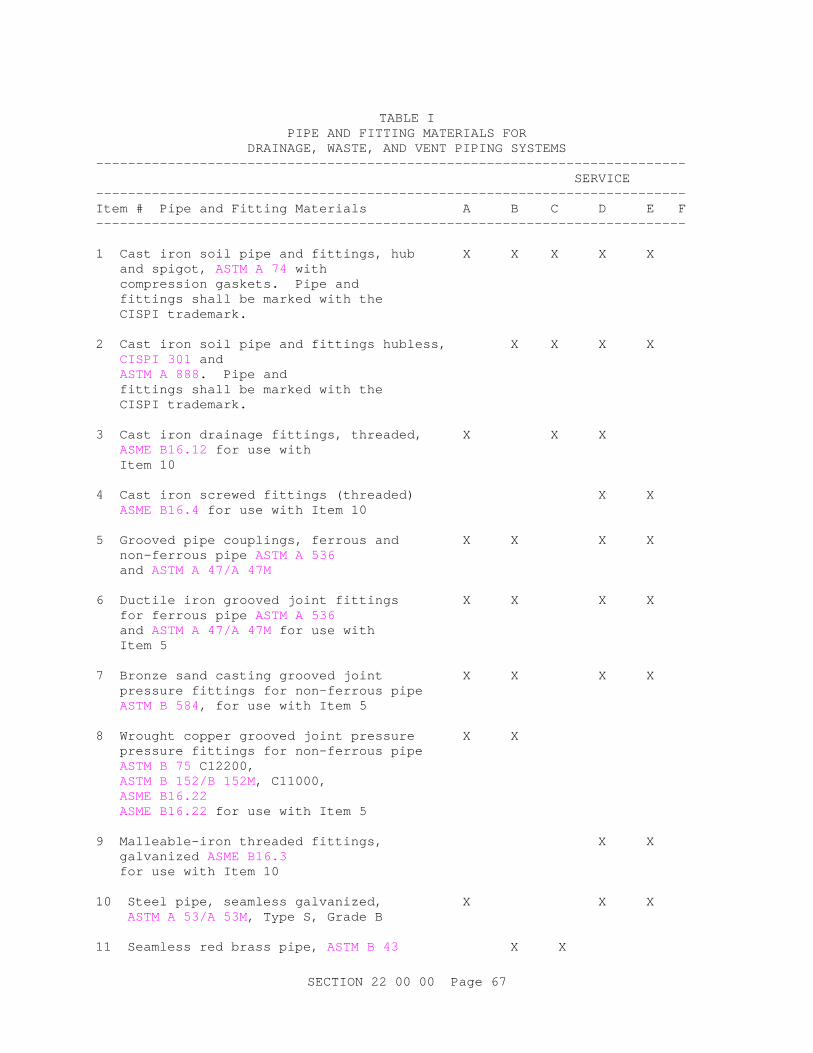
SECTION 22 00 00 Page 67
TABLE I
PIPE AND FITTING MATERIALS FOR DRAINAGE, WASTE, AND VENT PIPING SYSTEMS
-------------------------------------------------------------------------- SERVICE -------------------------------------------------------------------------- Item # Pipe and Fitting Materials A B C D E F -------------------------------------------------------------------------- 1 Cast iron soil pipe and fittings, hub X X X X X and spigot, ASTM A 74 with compression gaskets. Pipe and fittings shall be marked with the CISPI trademark. 2 Cast iron soil pipe and fittings hubless, X X X X CISPI 301 and ASTM A 888. Pipe and fittings shall be marked with the CISPI trademark. 3 Cast iron drainage fittings, threaded, X X X ASME B16.12 for use with Item 10 4 Cast iron screwed fittings (threaded) X X ASME B16.4 for use with Item 10 5 Grooved pipe couplings, ferrous and X X X X non-ferrous pipe ASTM A 536 and ASTM A 47/A 47M 6 Ductile iron grooved joint fittings X X X X for ferrous pipe ASTM A 536 and ASTM A 47/A 47M for use with Item 5 7 Bronze sand casting grooved joint X X X X pressure fittings for non-ferrous pipe ASTM B 584, for use with Item 5 8 Wrought copper grooved joint pressure X X pressure fittings for non-ferrous pipe ASTM B 75 C12200, ASTM B 152/B 152M, C11000, ASME B16.22 ASME B16.22 for use with Item 5 9 Malleable-iron threaded fittings, X X galvanized ASME B16.3 for use with Item 10 10 Steel pipe, seamless galvanized, X X X ASTM A 53/A 53M, Type S, Grade B 11 Seamless red brass pipe, ASTM B 43 X X
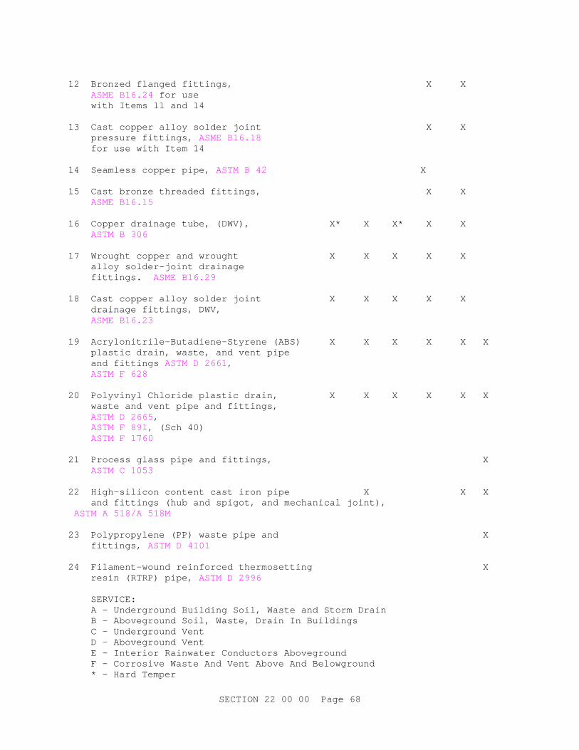
SECTION 22 00 00 Page 68
12 Bronzed flanged fittings, X X ASME B16.24 for use with Items 11 and 14 13 Cast copper alloy solder joint X X pressure fittings, ASME B16.18 for use with Item 14 14 Seamless copper pipe, ASTM B 42 X 15 Cast bronze threaded fittings, X X ASME B16.15 16 Copper drainage tube, (DWV), X* X X* X X ASTM B 306 17 Wrought copper and wrought X X X X X alloy solder-joint drainage fittings. ASME B16.29 18 Cast copper alloy solder joint X X X X X drainage fittings, DWV, ASME B16.23 19 Acrylonitrile-Butadiene-Styrene (ABS) X X X X X X plastic drain, waste, and vent pipe and fittings ASTM D 2661, ASTM F 628 20 Polyvinyl Chloride plastic drain, X X X X X X waste and vent pipe and fittings, ASTM D 2665, ASTM F 891, (Sch 40) ASTM F 1760 21 Process glass pipe and fittings, X ASTM C 1053 22 High-silicon content cast iron pipe X X X and fittings (hub and spigot, and mechanical joint), ASTM A 518/A 518M 23 Polypropylene (PP) waste pipe and X fittings, ASTM D 4101 24 Filament-wound reinforced thermosetting X resin (RTRP) pipe, ASTM D 2996 SERVICE: A - Underground Building Soil, Waste and Storm Drain B - Aboveground Soil, Waste, Drain In Buildings C - Underground Vent D - Aboveground Vent E - Interior Rainwater Conductors Aboveground F - Corrosive Waste And Vent Above And Belowground * - Hard Temper
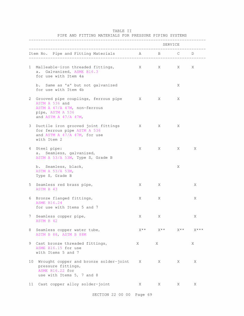
SECTION 22 00 00 Page 69
TABLE II PIPE AND FITTING MATERIALS FOR PRESSURE PIPING SYSTEMS
-------------------------------------------------------------------------- SERVICE -------------------------------------------------------------------------- Item No. Pipe and Fitting Materials A B C D -------------------------------------------------------------------------- 1 Malleable-iron threaded fittings, X X X X a. Galvanized, ASME B16.3 for use with Item 4a b. Same as "a" but not galvanized X for use with Item 4b 2 Grooved pipe couplings, ferrous pipe X X X ASTM A 536 and ASTM A 47/A 47M, non-ferrous pipe, ASTM A 536 and ASTM A 47/A 47M, 3 Ductile iron grooved joint fittings X X X for ferrous pipe ASTM A 536 and ASTM A 47/A 47M, for use with Item 2 4 Steel pipe: X X X X a. Seamless, galvanized, ASTM A 53/A 53M, Type S, Grade B b. Seamless, black, X ASTM A 53/A 53M, Type S, Grade B 5 Seamless red brass pipe, X X X ASTM B 43 6 Bronze flanged fittings, X X X ASME B16.24 for use with Items 5 and 7 7 Seamless copper pipe, X X X ASTM B 42 8 Seamless copper water tube, X** X** X** X*** ASTM B 88, ASTM B 88M 9 Cast bronze threaded fittings, X X X ASME B16.15 for use with Items 5 and 7 10 Wrought copper and bronze solder-joint X X X X pressure fittings, ASME B16.22 for use with Items 5, 7 and 8 11 Cast copper alloy solder-joint X X X X
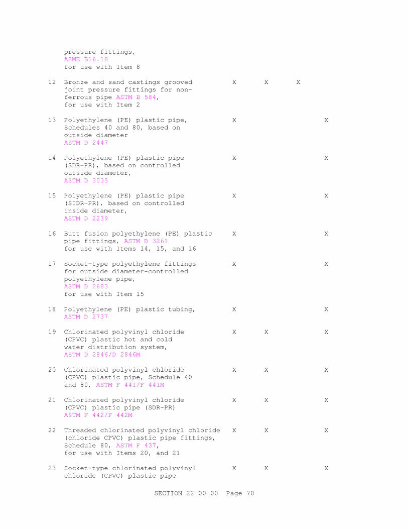
SECTION 22 00 00 Page 70
pressure fittings, ASME B16.18 for use with Item 8 12 Bronze and sand castings grooved X X X joint pressure fittings for non- ferrous pipe ASTM B 584, for use with Item 2 13 Polyethylene (PE) plastic pipe, X X Schedules 40 and 80, based on outside diameter ASTM D 2447 14 Polyethylene (PE) plastic pipe X X (SDR-PR), based on controlled outside diameter, ASTM D 3035 15 Polyethylene (PE) plastic pipe X X (SIDR-PR), based on controlled inside diameter, ASTM D 2239 16 Butt fusion polyethylene (PE) plastic X X pipe fittings, ASTM D 3261 for use with Items 14, 15, and 16 17 Socket-type polyethylene fittings X X for outside diameter-controlled polyethylene pipe, ASTM D 2683 for use with Item 15 18 Polyethylene (PE) plastic tubing, X X ASTM D 2737 19 Chlorinated polyvinyl chloride X X X (CPVC) plastic hot and cold water distribution system, ASTM D 2846/D 2846M 20 Chlorinated polyvinyl chloride X X X (CPVC) plastic pipe, Schedule 40 and 80, ASTM F 441/F 441M 21 Chlorinated polyvinyl chloride X X X (CPVC) plastic pipe (SDR-PR) ASTM F 442/F 442M 22 Threaded chlorinated polyvinyl chloride X X X (chloride CPVC) plastic pipe fittings, Schedule 80, ASTM F 437, for use with Items 20, and 21 23 Socket-type chlorinated polyvinyl X X X chloride (CPVC) plastic pipe

SECTION 22 00 00 Page 71
fittings, Schedule 40, ASTM F 438 for use with Items 20, 21, and 22 24 Socket-type chlorinated polyvinyl X X X chloride (CPVC) plastic pipe fittings Schedule 80, ASTM F 439 for use with Items 20, 21, and 22 25 Polyvinyl chloride (PVC) plastic pipe, X X Schedules 40, 80, and 120, ASTM D 1785 26 Polyvinyl chloride (PVC) pressure-rated X X pipe (SDR Series), ASTM D 2241 27 Polyvinyl chloride (PVC) plastic pipe X X fittings, Schedule 40, ASTM D 2466 28 Socket-type polyvinyl chloride (PVC) X X plastic pipe fittings, schedule 80, ASTM D 2467 for use with Items 26 and 27 29 Threaded polyvinyl chloride (PVC) X X plastic pipe fittings, schedule 80, ASTM D 2464 30 Joints for IPS pvs pipe using solvent X X cement, ASTM D 2672 31 Filament-wound reinforced X X thermosetting resin (RTRP) pipe, ASTM D 2996 32 Steel pipeline flanges, X X MSS SP-44 33 Fittings: brass or bronze; X X ASME B16.15, and ASME B16.18 ASTM B 828 34 Carbon steel pipe unions, X X X socket-welding and threaded, MSS SP-83 35 Malleable-iron threaded pipe X X unions ASME B16.39 36 Nipples, pipe threaded X X X ASTM A 733 37 Crosslinked Polyethylene (PEX) X X X Plastic Pipe ASTM F 877.

SECTION 22 00 00 Page 72
38 Press Fittings X X A - Cold Water Service Aboveground B - Hot and Cold Water Distribution 180 degrees F Maximum Aboveground C - Compressed Air Lubricated D - Cold Water Service Belowground Indicated types are minimum wall thicknesses. ** - Type L - Hard *** - Type K - Hard temper with brazed joints only or type K-soft temper without joints in or under floors **** - In or under slab floors only brazed joints

SECTION 22 00 00 Page 73
TABLE III
STANDARD RATING CONDITIONS AND MINIMUM PERFORMANCE RATINGS FOR WATER HEATING EQUIPMENT (I-P) ----------------------------------------------------------------------------- STORAGE INPUT CAPACITY BTUH/ RATING TEST REQUIRED FUEL GALLONS GALLON BTUH PROCEDURE PERFORMANCE------------------------------------------------------------------------------ A. STORAGE WATER HEATERS Elec 60 max. 10 CFR 430 EF = 0.93 Elec 60 min. 10 CFR 430 EF = 0.91 Elec 20 min. 12 kW max. 10 CFR 430 EF = 0.93-0.00132V min. Elec 20 min. 12 kW min. CSA/AM Z21.10.3 SL = 20+35x(V^^1/2)max. Heat <=24 Amps 10 CFR 430 EF = 0.93-0.00132V Pump <=250 Volts Gas 50 max. 10 CFR 430 EF = 0.62 Gas 20 min. 75,000 10 CFR 430 EF = 0.62-0.0019V max. min. Gas 1,000 75,000 CSA/AM Z21.10.3 ET = 80 percent min. SL = 1.3+38/V max. Oil 20 min. 105,000 10 CFR 430 EF = 0.80-0.0019V min. max. Oil 4,000 105,000 CSA/AM Z21.10.3 ET = 78 percent; SL = 1.3+38/V max. B. Unfired Hot Water Storage R-12.5 min. C. Instantaneous Water Heater Gas <2 4,000 >50,000 10 CFR 430 EF = 0.62-0.0019V <200,000 Gas <10 4,000 >200,000 CSA/AM Z21.10.3 ET = 80 percent Gas <10 4,000 <200,000 CSA/AM Z21.10.3 ET = 80 percent SL = (Q/800+110x(V^^1/2)) Oil <2 4,000 >50,000 10 CFR 430 EF = 0.59-0.0019V <210,000 SL = (Q/800+110x(V^^1/2)) Oil <10 4,000 >210,000 CSA/AM Z21.10.3 ET = 80 percent Oil >10 4,000 >210,000 CSA/AM Z21.10.3 ET = 78 percent SL = (Q/800+110x(V^^1/2))max

SECTION 22 00 00 Page 74
D. Pool Heaters Gas All All ASHRAE 146 ET = 78 percent Oil All All ASHRAE 146 ET = 78 percent Heat All All ASHRAE 146 COP = 4.0 Pump TERMS: EF = Energy factor, minimum overall efficiency. ET = Minimum thermal efficiency with 70 degrees F delta T. SL = Standby loss is maximum Btu/h based on a 70 degree F temperature difference between stored water and ambient requirements. V = Rated storage volume in gallons Q = Nameplate input rate in Btu/h -- End of Section --