openhcipeople.ee.ethz.ch/~jbeutel/projects/bluetooth/open_hci_1.pdf · proposal, specification, or...
TRANSCRIPT

OpenHCI Open Host Controller Interface Specification
for USB
Compaq
Microsoft
National Semiconductor
10/06/00 4:40 PM
Release: 1.0a

OpenHCI - Open Host Controller Interface Specification for USB
ii
Adopter’s Agreement for
Open Host Controller Interface Reciprocal Covenant READ THIS PRIOR TO IMPLEMENTATION OF THIS SPECIFICATION. IMPLEMENTATION OF THIS SPECIFICATION SHALL CONSTITUTE YOUR LEGALLY BINDING ACCEPTANCE OF THE TERMS OFFERED IN THIS PATENT COVENANT AGREEMENT. IF AN ENTITY DOES NOT ACCEPT THE TERMS OFFERED IN THIS PATENT COVENANT AGREEMENT, SUCH ENTITY IS NOT A RECIPIENT OF THE COVENANT CONTAINED HEREIN AND SHOULD NOT IMPLEMENT THE SPECIFICATION. THE PROMOTERS REQUEST THAT SUCH ENTITY RETURN THE SPECIFICATION TO THE PROMOTERS. This is a patent covenant agreement by parties wishing to adopt Open HCI. As used in this Agreement: ?? The ”Promoters” are the parties who have initially adopted Open HCI. A list of their
names is available upon request to the Open HCI Clerk; initially the Clerk is Compaq Computer Corporation.
?? “Adopter” is the entity that has accepted this Agreement. ?? “Fellow Adopters” are the Promoters and any other entity which has accepted an
identical counterpart of this Agreement. ?? “Affiliate” is an entity which directly or indirectly controls, is controlled by, or is under
common control with another entity, so long as such control exists. “Control” means beneficial ownership of more than fifty percent of the voting stock or equity in an entity.
?? “Specification” means the document entitled “Open Host Controller Interface Specification, revision 1.0,” authored and published by the Promoters and any Updates identified as set out in Section 2.
1. Covenants 1.1. Grants of Covenants. The following covenant has been granted by the Promoters to
each other. Upon Adopter’s execution of this Agreement, it is granted by Adopter to all Fellow Adopters, and the grants of all Fellow Adopters shall extend to Adopter. In each case, the party (Promoter, Adopter, or Fellow Adopter) granting the covenant is referred to as the “Grantor.”

OpenHCI - Open Host Controller Interface Specification for USB
iii
Subject to the other terms of this Agreement, Grantor, on behalf of itself and its Affiliates, covenants not to sue or otherwise assert a claim against any Fellow Adopter or its Affiliates, or its customers, subcontractors, resellers, or users, based upon the manufacture, use, lease, sale or other transfer of any product that infringes a claim of a patent held by Grantor, which claim is infringed by:
(i) the implementation or use of the methods, protocols, interfaces, or interoperability criteria set out in the Specification, or (ii) any apparatus required by the Specification which is required to implement such methods, protocols, interfaces, or interoperability criteria; where such infringement would not have occurred but for the implementation of the Specification, and where such infringement either: (a) could not have been avoided by another commercially reasonable implementation of the Specification, or (b) resulted from use of an example included in the Specification. The foregoing covenant not to sue extends to any entity which is not a Fellow Adopter only to the extent that such entity grants a reciprocal covenant, either expressly or by implication through the non-assertion of such claims against Grantor or a Fellow Adopter.
1.2. Acceptance of Covenants. Adopter hereby accepts the covenants granted by the Fellow Adopters.
2. Open HCI Specification Administration, Access and Updates 2.1. Administration. The Promoters may designate a “Clerk” from time to time. Initially,
the Clerk will be Compaq Computer Corporation. The Clerk is responsible for: 2.1.1. Maintaining current copies of the Specification and providing access to such
copies to the Fellow Adopters upon request. 2.2. Limits on Clerk. The Clerk is not an agent of the Promoters or Fellow Adopters.
The Promoters may designate a replacement Clerk at any time. The Clerk may resign as Clerk at will.
2.3. Access. Fellow Adopters may purchase copies or download the Specification. 2.4. Updates. The Promoters may issue an update, revision, or extension of some or all
of the Specification (an “Update”) on or prior to June 1, 1997. Provided that the Promoters have made the Specification generally available with the notation “Implementation of this Specification is governed by the terms of the Open HCI Covenant,” the covenants referenced in this Agreement shall extend to the Update except as specifically provided below. Issuing such an Update shall NOT terminate any right or obligation of Adopter under this Agreement, including the covenants granted with respect to the earlier versions of the Specification.

OpenHCI - Open Host Controller Interface Specification for USB
iv
2.5. Objection and Withdrawal. Adopter (or a Fellow Adopter) may, within 60 days after
publication of an Update, terminate this Agreement with respect to such Update and all further revisions of the Specification. Termination shall be made by giving written notice to the Promoters. The effect of such termination will be that the covenants granted shall continue to apply with respect to the Specification and Updates adopted as of 60 days prior to the date of termination shall continue in full force and shall extend to entities who become Adopters even after such termination. No covenant shall be deemed granted or received by such Adopter as to Updates adopted after the date of such withdrawal.
3. General 3.1. No Other Licenses. Adopter neither grants nor receives any license to or right to
use any trademark, tradename, copyright, or maskwork hereunder. Except for the rights expressly provided by this Agreement, Adopter neither grants nor receives, by implication, or estoppel, or otherwise, any rights under any patents or other intellectual property rights.
3.2. Limited Effect. This Agreement shall not be construed to waive any Party’s rights under law or any other agreement except as expressly set out here.
3.3. No Warranty. Adopter acknowledges that the Specification is provided “AS IS” WITH NO WARRANTIES WHATSOEVER, WHETHER EXPRESS, IMPLIED OR STATUTORY, INCLUDING, BUT NOT LIMITED TO ANY WARRANTY OF MERCHANTABILITY, NONINFRINGEMENT, FITNESS FOR ANY PARTICULAR PURPOSE, OR ANY WARRANTY OTHERWISE ARISING OUT OF ANY PROPOSAL, SPECIFICATION, OR SAMPLE.
3.4. Damages. In no event will Promoters, Adopter or Fellow Adopter be liable to the other for any loss of profits, loss of use, incidental, consequential, indirect, or special damages arising out of this or any other Open HCI Covenant, whether or not such party had advance notice of the possibility of such damages.
3.5. Governing Law. This Agreement shall be construed and controlled by the laws of New York. Any litigation arising out of this Agreement shall take place in New York, and all parties consent to jurisdiction of the State and Federal courts there.
3.6. Not Partners. Adopter understands that the Promoters are independent companies and are not partners or joint venturers with each other. While the Promoters may select an entity to handle certain administrative tasks for them, no party is authorized to make any commitment on behalf of all or any of them.
3.7. Complete Agreement. Upon publication of the Specification by the Promoters, this Agreement sets forth the entire understanding of the agreement between the Adopters and the Promoters and supersedes all prior agreements and understandings relating hereto. No modifications or additions to or deletions from this Agreement shall be binding unless accepted in writing by an authorized representative of all parties.
OpenHCI - Open Host Controller Interface Specification for USB
v
Compaq Computer Corporation ____________________ John Rose Senior Vice President Commercial Desktop Division
Microsoft Corporation By:__________________ Name Title
National Semiconductor Corporation By: Name Title
Revision Table
Revision Number Revision Date Changes Made 1.0a 10/6/00 Added Appendix B, Legacy Support
Interface Specification

OpenHCI - Open Host Controller Interface Specification for USB
vi
TABLE OF CONTENTS
1. INTRODUCTION ..................................................................................................................... 1
2. TERMS AND ABBREVIATIONS.......................................................................................... 2
3. ARCHITECTURAL OVERVIEW........................................................................................... 6
3.1 Introduction....................................................................................................................... 6
3.2 Data Transfer Types........................................................................................................ 7
3.3 Host Controller Interface................................................................................................ 7 3.3.1 Communication Channels ..................................................................................................7 3.3.2 Data Structures .................................................................................................................8
3.4 Host Controller Driver Responsibilities ...................................................................13 3.4.1 Host Controller Management...........................................................................................13 3.4.2 Bandwidth Allocation......................................................................................................13 3.4.3 List Management.............................................................................................................14 3.4.4 Root Hub........................................................................................................................14
3.5 Host Controller Responsibilities................................................................................14 3.5.1 USB States.....................................................................................................................14 3.5.2 Frame management .........................................................................................................15 3.5.3 List Processing................................................................................................................15
4. DATA STRUCTURES..........................................................................................................16
4.1 Overview ..........................................................................................................................16
4.2 Endpoint Descriptor......................................................................................................17 4.2.1 Endpoint Descriptor Format ............................................................................................17 4.2.2 Endpoint Descriptor Field Definitions...............................................................................18 4.2.3 Endpoint Descriptor Description......................................................................................19
4.3 Transfer Descriptors.....................................................................................................20 4.3.1 General Transfer Descriptor ............................................................................................20
4.3.1.1 General Transfer Descriptor Format .........................................................................21 4.3.1.2 General Transfer Descriptor Field Definitions ............................................................21 4.3.1.3 General Transfer Descriptor Description...................................................................22
4.3.1.3.1 Buffer Address Determination............................................................................22 4.3.1.3.2 Packet Size .......................................................................................................22 4.3.1.3.3 Condition Codes...............................................................................................23 4.3.1.3.4 Sequence Bits ...................................................................................................23 4.3.1.3.5 Transfer Completion..........................................................................................24 4.3.1.3.6 Transfer Errors..................................................................................................24

OpenHCI - Open Host Controller Interface Specification for USB
vii
4.3.1.3.6.1 Transmission Errors....................................................................................25 4.3.1.3.6.2 Sequence Errors ........................................................................................25 4.3.1.3.6.3 System Errors ............................................................................................27
4.3.1.3.7 Special Handling ...............................................................................................27 4.3.1.3.7.1 NAK.........................................................................................................27 4.3.1.3.7.2 Stall ...........................................................................................................27
4.3.2 Isochronous Transfer Descriptor......................................................................................27 4.3.2.1 Isochronous Transfer Descriptor Format...................................................................27 4.3.2.2 Isochronous Transfer Descriptor Field Definitions .....................................................28 4.3.2.3 Isochronous Transfer Descriptor Description............................................................28
4.3.2.3.1 Buffer Addressing .............................................................................................29 4.3.2.3.2 Data Packet Size...............................................................................................30 4.3.2.3.3 Status ...............................................................................................................30 4.3.2.3.4 Transfer Completion..........................................................................................30 4.3.2.3.5 Transfer Errors..................................................................................................30
4.3.2.3.5.1 Transmission Errors....................................................................................31 4.3.2.3.5.2 Sequence Errors ........................................................................................31 4.3.2.3.5.3 Time Errors................................................................................................31 4.3.2.3.5.4 System Errors ............................................................................................33
4.3.2.3.6 Special Handling ...............................................................................................34 4.3.2.3.6.1 NAK and STALL......................................................................................34
4.3.2.4 PacketStatusWord...................................................................................................34 4.3.2.4.1 Packet Status Word Field Definitions.................................................................34
4.3.3 Completion Codes ..........................................................................................................35 4.3.3.1 Condition Code Description.....................................................................................36
4.4 Host Controller Communications Area....................................................................36 4.4.1 Host Controller Communications Area Format.................................................................37 4.4.2 Host Controller Communications Area Description..........................................................37
4.4.2.1 HccaInterruptTable ..................................................................................................37 4.4.2.2 HccaFrameNumber .................................................................................................38 4.4.2.3 HccaDoneHead .......................................................................................................38
4.5 Endpoint List Processing............................................................................................39
4.6 Transfer Descriptor Queue Processing...................................................................40
5. HOST CONTROLLER DRIVER .........................................................................................41
5.1 Host Controller Management......................................................................................41 5.1.1 Initialization.....................................................................................................................41
5.1.1.1 Load and Locate......................................................................................................42 5.1.1.2 Verify Host Controller and Allocate Resources .........................................................42 5.1.1.3 Take Control of Host Controller...............................................................................43
5.1.1.3.1 SMM Driver, Power-Up...................................................................................43

OpenHCI - Open Host Controller Interface Specification for USB
viii
5.1.1.3.2 BIOS Driver .....................................................................................................43 5.1.1.3.3 OS Driver, SMM Active ...................................................................................44 5.1.1.3.4 OS Driver, BIOS Active ...................................................................................44 5.1.1.3.5 OS Driver, neither SMM nor BIOS...................................................................44 5.1.1.3.6 SMM Driver, Re-Entry.....................................................................................45
5.1.1.4 Setup Host Controller ..............................................................................................45 5.1.1.5 Begin Sending SOFs................................................................................................45
5.1.2 Operational States...........................................................................................................46 5.1.2.1 USBRESET................................................................................................................46 5.1.2.2 USBOPERATIONAL...................................................................................................46 5.1.2.3 USBSUSPEND ...........................................................................................................46 5.1.2.4 USBRESUME ............................................................................................................47
5.2 Schedule ..........................................................................................................................47 5.2.1 Sample Host Controller Driver Definitions........................................................................49 5.2.2 Miscellaneous Definitions.................................................................................................49 5.2.3 Host Controller Descriptors Definitions............................................................................50 5.2.4 Host Controller Driver Descriptor Definitions...................................................................51 5.2.5 Host Controller Endpoints ...............................................................................................53 5.2.6 Host Controller Driver Internal Definitions........................................................................54 5.2.7 Endpoint Descriptor Lists ................................................................................................57
5.2.7.1 Bulk and Control......................................................................................................57 5.2.7.1.1 Adding..............................................................................................................57 5.2.7.1.2 Removing..........................................................................................................59 5.2.7.1.3 Pause................................................................................................................62
5.2.7.2 Interrupt...................................................................................................................64 5.2.7.2.1 Polling Rate.......................................................................................................67 5.2.7.2.2 Adding..............................................................................................................69 5.2.7.2.3 Removing..........................................................................................................69 5.2.7.2.4 Pause................................................................................................................70
5.2.7.3 Isochronous .............................................................................................................70 5.2.7.3.1 Adding..............................................................................................................71 5.2.7.3.2 Removing..........................................................................................................71 5.2.7.3.3 Pause................................................................................................................71
5.2.8 Transfer Descriptor Queues.............................................................................................71 5.2.8.1 The NULL or Empty Queue.....................................................................................71 5.2.8.2 Adding to a Queue...................................................................................................72 5.2.8.3 Removing from a Queue...........................................................................................76 5.2.8.4 Cancel.....................................................................................................................77
5.2.9 Done Queue ...................................................................................................................78 5.2.10 USB Bandwidth Allocation............................................................................................81
5.2.10.1 Scheduling Overrun Errors .....................................................................................81 5.2.11 ControlBulkServiceRatio...............................................................................................82

OpenHCI - Open Host Controller Interface Specification for USB
ix
5.3 Host Controller Interrupt..............................................................................................83
5.4 FrameInterval Counter..................................................................................................88
5.5 Root Hub..........................................................................................................................89

OpenHCI - Open Host Controller Interface Specification for USB
x
6. HOST CONTROLLER..........................................................................................................90
6.1 Introduction.....................................................................................................................90
6.2 USB States ......................................................................................................................90 6.2.1 UsbOperational...............................................................................................................91 6.2.2 UsbReset........................................................................................................................92 6.2.3 UsbSuspend ...................................................................................................................92 6.2.4 UsbResume ....................................................................................................................92
6.3 Frame Management.......................................................................................................93 6.3.1 Frame Timing..................................................................................................................93 6.3.2 StartOfFrame (SOF) Token Generation ..........................................................................94 6.3.3 HccaFrameNumber Update ............................................................................................94
6.4 List Processing ..............................................................................................................95 6.4.1 Priority............................................................................................................................95
6.4.1.1 List Priority..............................................................................................................96 6.4.1.1.1 Periodic Lists ....................................................................................................96 6.4.1.1.2 Nonperiodic Lists..............................................................................................96
6.4.1.2 Endpoint Descriptor Priority.....................................................................................98 6.4.1.3 Transfer Descriptor Priority......................................................................................99
6.4.2 List Service Flow............................................................................................................99 6.4.2.1 List Enabled Check..................................................................................................99 6.4.2.2 Locating Endpoint Descriptors................................................................................101
6.4.3 Endpoint Descriptor Processing.....................................................................................102 6.4.4 Transfer Descriptor Processing......................................................................................103
6.4.4.1 Isochronous Relative Frame Number Calculation....................................................103 6.4.4.2 Packet Address and Size Calculation......................................................................103 6.4.4.3 Packet Transfer Time Check..................................................................................105 6.4.4.4 Largest Data Packet Counter Operation.................................................................106 6.4.4.5 Status Writeback ...................................................................................................106
6.4.4.5.1 General Transfer Descriptor Status Writeback.................................................106 6.4.4.5.2 Isochronous Transfer Descriptor Status Writeback ..........................................107
6.4.4.6 Transfer Descriptor Retirement ...............................................................................107 6.4.5 Done Queue .................................................................................................................108
6.4.5.1 Done Queue Interrupt Counter ...............................................................................108
6.5 Interrupt Processing...................................................................................................109 6.5.1 SchedulingOverrun Event ..............................................................................................109 6.5.2 WritebackDoneHead Event...........................................................................................110 6.5.3 StartOfFrame Event ......................................................................................................110 6.5.4 ResumeDetected Event .................................................................................................110 6.5.5 UnrecoverableError Event .............................................................................................110 6.5.6 FrameNumberOverflow Event.......................................................................................110
OpenHCI - Open Host Controller Interface Specification for USB
xi
6.5.7 RootHubStatusChange Event ........................................................................................111 6.5.8 OwnershipChange Event ...............................................................................................111
6.6 Root Hub........................................................................................................................111
7. OPERATIONAL REGISTERS...........................................................................................112
7.1 The Control and Status Partition .............................................................................113 7.1.1 HcRevision Register .....................................................................................................113 7.1.2 HcControl Register ......................................................................................................113 7.1.3 HcCommandStatus Register........................................................................................116 7.1.4 HcInterruptStatus Register ..........................................................................................117 7.1.5 HcInterruptEnable Register.........................................................................................120 7.1.6 HcInterruptDisable Register ........................................................................................121
7.2 Memory Pointer Partition...........................................................................................122 7.2.1 HcHCCA Register........................................................................................................122 7.2.2 HcPeriodCurrentED Register......................................................................................122 7.2.3 HcControlHeadED Register.........................................................................................123 7.2.4 HcControlCurrentED Register ....................................................................................123 7.2.5 HcBulkHeadED Register..............................................................................................124 7.2.6 HcBulkCurrentED Register..........................................................................................124 7.2.7 HcDoneHead Register..................................................................................................125
7.3 Frame Counter Partition.............................................................................................125 7.3.1 HcFmInterval Register.................................................................................................125 7.3.2 HcFmRemaining Register ............................................................................................126 7.3.3 HcFmNumber Register ................................................................................................127 7.3.4 HcPeriodicStart Register .............................................................................................127 7.3.5 HcLSThreshold Register...............................................................................................128
7.4 Root Hub Partition.......................................................................................................128 7.4.1 HcRhDescriptorA Register...........................................................................................129 7.4.2 HcRhDescriptorB Register ...........................................................................................130 7.4.3 HcRhStatus Register.....................................................................................................131 7.4.4 HcRhPortStatus[1:NDP] Register ................................................................................133
APPENDIX A—PCI INTERFACE.........................................................................................132
PCI CONFIGURATION ...........................................................................................................137
PCI Configuration Spaces for OpenHCI-compliant USB Host Controller ...........138 COMMAND Register ............................................................................................................139 CLASS_CODE Register........................................................................................................139 BAR_OHCI Register..............................................................................................................140
OpenHCI - Open Host Controller Interface Specification for USB
xii
APPENDIX B—LEGACY SUPPORT INTERFACE SPECIFICATION ..........................136
OVERVIEW...............................................................................................................................141
OPERATIONAL THEORY......................................................................................................142
Keyboard/Mouse Input .....................................................................................................142
Keyboard Output................................................................................................................143
Emulation Interrupts..........................................................................................................143 Mixed Environment ................................................................................................................144 Gate A20 Sequence...............................................................................................................144
SYSTEM REQUIREMENTS ..................................................................................................145
Host Controller Mapping..................................................................................................145
SMI Signaling.......................................................................................................................146
Intercept Port 60h and 64h Accesses ...........................................................................146
Interrupts ..............................................................................................................................146
Run-time Memory...............................................................................................................146
PROGRAMMING INTERFACE .............................................................................................147
Modifications to existing registers.................................................................................147 HcRevision Register ..............................................................................................................147
Legacy Support Registers...............................................................................................147 HceInput Register..................................................................................................................148 HceOutput Register...............................................................................................................148 HceStatus Register................................................................................................................149 HceControl Register..............................................................................................................150
IMPLEMENTATION NOTES..................................................................................................151
Emulation Interrupt Decode ............................................................................................151
A20 Gate................................................................................................................................151

OpenHCI - Open Host Controller Interface Specification for USB
xiii
LIST OF FIGURES Figure 3-1: USB Focus Areas ...........................................................................................................6 Figure 3-2: Communication Channels.................................................................................................8 Figure 3-3: Typical List Structure......................................................................................................10 Figure 3-4: Interrupt ED Structure...................................................................................................11 Figure 3-5: Sample Interrupt Endpoint Schedule ..............................................................................12 Figure 3-6: Frame Bandwidth Allocation...........................................................................................13 Figure 4-1: Endpoint Descriptor .......................................................................................................17 Figure 4-2: General TD Format........................................................................................................21 Figure 4-3: Isochronous TD Format .................................................................................................27 Figure 4-4: Packet Status Word Format ...........................................................................................34 Figure 4-5: Host Controller Communications Area Format................................................................37 Figure 5-1: The OpenHCI Host Controller .......................................................................................42 Figure 5-2: USB Schedule................................................................................................................48 Figure 5-3: Removing an Endpoint Descriptor...................................................................................59 Figure 5-4: Structure of Interrupt Lists .............................................................................................64 Figure 5-5: Runtime Structure of Interrupt Lists.................................................................................65 Figure 5-6: An Empty Transfer Descriptor Queue .............................................................................71 Figure 5-7: Adding a Transfer Descriptor to a Queue........................................................................72 Figure 5-8: Host Controller Removes a Transfer Descriptor from a Queue ........................................76 Figure 6-1: USB States ...................................................................................................................91 Figure 6-2: Timing for SOF Token Generation on USB....................................................................94 Figure 6-3: List Priority within a USB Frame.....................................................................................95 Figure 6-4: Control Bulk Service Ratio of 4:1 ...................................................................................97 Figure 6-5: List Service Flow.........................................................................................................100 Figure 6-6: Endpoint Descriptor Service Flow................................................................................102 Figure 6-7: Transfer Descriptor Service Flow.................................................................................104

OpenHCI - Open Host Controller Interface Specification for USB
xiv
Figure 7-1: HcRevision Register.....................................................................................................113 Figure 7-2: HcControl Register......................................................................................................113 Figure 7-3: HcCommandStatus Register .......................................................................................116 Figure 7-4: HcInterruptStatus Register..........................................................................................118 Figure 7-5: HcInterruptEnable Register ........................................................................................120 Figure 7-6: HcInterruptDisable Register........................................................................................121 Figure 7-7: HcHCCA Register .......................................................................................................122 Figure 7-8: HcPeriodCurrentED Register .....................................................................................122 Figure 7-9: HcControlHeadED Register........................................................................................123 Figure 7-10: HcControlCurrentED Register..................................................................................123 Figure 7-11: HcBulkHeadED Register...........................................................................................124 Figure 7-12: HcBulkCurrentED Register.......................................................................................124 Figure 7-13: HcDoneHead Register...............................................................................................125 Figure 7-14: HcFmInterval Register..............................................................................................125 Figure 7-15: HcFmRemaining Register..........................................................................................126 Figure 7-16: HcFmNumber Register..............................................................................................127 Figure 7-17: HcPeriodicStart Register...........................................................................................127 Figure 7-18: HcLSThreshold Register............................................................................................128 Figure 7-19: HcRhDescriptorA Register ........................................................................................129 Figure 7-20: HcRhDescriptorB Register.........................................................................................130 Figure 7-21: HcRhStatus Register..................................................................................................131 Figure 7-22: HcRhPortStatus Register...........................................................................................133 Figure B-1: HcRevision Register...................................................................................................142

OpenHCI - Open Host Controller Interface Specification for USB
xv
LIST OF TABLES Table 4-1: Field Definitions for Endpoint Descriptor..........................................................................18 Table 4-2: Field Definitions for General TD.......................................................................................21 Table 4-3: Field Definitions for Isochronous TD................................................................................28 Table 4-4: Example Calculation of R and Host Controller Action.......................................................29 Table 4-5: Example of Time Overrun................................................................................................33 Table 4-6: Field Definitions for Packet Status Word..........................................................................34 Table 4-7: Completion Codes ..........................................................................................................35 Table 5-1: LIST_ENTRY................................................................................................................49 Table 5-2: HCD_ENDPOINT_DESCRIPTOR...............................................................................51 Table 5-3: HCD_TRANSFER_DESCRIPTOR...............................................................................52 Table 5-4: HCD_ENDPOINT.........................................................................................................53 Table 5-5: USBD_REQUEST.........................................................................................................54 Table 5-6: HCD_ED_LIST..............................................................................................................55 Table 5-7: HCD_DEVICE_DATA..................................................................................................56 Table 7-1: Host Controller Operational Registers............................................................................112 Table B-1: HcRevision Register Fields...........................................................................................142 Table B-2: Legacy Support Registers .............................................................................................142 Table B-3: Emulated Registers........................................................................................................143 Table B-4: HceInput Registers.......................................................................................................143 Table B-5: HceOutput Registers....................................................................................................143 Table B-6: HceStatus Register.......................................................................................................144 Table B-7: HceControl Register ....................................................................................................145

OpenHCI - Open Host Controller Interface Specification for USB
1
1. INTRODUCTION The Open Host Controller Interface (OpenHCI) Specification for the Universal Serial Bus is a register-level description of a Host Controller for the Universal Serial Bus (USB) which in turn is described by the Universal Serial Bus Specification, soon to be released by Intel Corporation. The purpose of OpenHCI is to accelerate the acceptance of USB in the marketplace by promoting the use of a common industry software/hardware interface. OpenHCI allows multiple Host Controller vendors to design and sell Host Controllers with a common software interface, freeing them from the burden of writing and distributing software drivers. The design goal has been to balance the complexity of the hardware and software so that OpenHCI is more than the simplest possible Host Controller for USB yet not the most complex possible. The target audience for this specification are hardware designers, system vendors, and software designers. The reader should be familiar with the Universal Serial Bus Specification, Version 1.0, which is included by reference. In the chapters that follow, the Host Controller is described from various viewpoints; as a result, some information is repeated with the details of the current viewpoint being highlighted and explained. It is hoped that this method of presentation will give the reader a deeper and less ambiguous understanding of the specification. The following descriptions summarize the organization of this specification:
?? Chapter 2 provides a glossary of terms and abbreviations used within the specification. ?? Chapter 3 gives an overview of the architecture of the Host Controller. ?? Chapter 4 defines the data structures that reside in the host system memory and are used by the
Host Controller. ?? Chapter 5 describes how a software driver manages the Host Controller and its data structures. ?? Chapter 6 describes the Host Controller hardware. ?? Chapter 7 details the registers within the Host Controller that are visible to the software.

OpenHCI - Open Host Controller Interface Specification for USB
2
2. TERMS AND ABBREVIATIONS
Bit Stuffing Insertion of a “0” bit into a data stream to cause an electrical transition on the data wires allowing a PLL to remain locked.
Buffer Storage used to compensate for a difference in data rates or time of
occurrence of events, when transmitting data from one device to another.
Command A request made to a Universal Serial Bus (USB) device.
Cyclic Redundancy Check (CRC)
A check performed on data to see if an error has occurred in transmitting, reading, or writing the data. The result of a CRC is typically stored or transmitted with the checked data. The stored or transmitted result is compared to a CRC calculated for the data to determine if an error has occurred.
Device A logical or physical entity that performs one or more functions. The
actual entity described depends on the context of the reference. At the lowest level, device may refer to a single hardware component, as in a memory device. At a higher level, it may refer to a collection of hardware components that perform a particular function, such as a Universal Serial Bus (USB) interface device. At an even higher level, device may refer to the function performed by an entity attached to the USB; for example, a data/FAX modem device. Devices may be physical, electrical, addressable, and logical. When used as a nonspecific reference, a USB device is either a hub or a function.
Device Address The address of a device on Universal Serial Bus (USB). The Device
Address is the Default Address when the USB device is first powered or reset. Hubs and functions are assigned a unique Device Address by USB configuration software.
Driver When referring to hardware, an I/O pad that drives an external load.
When referring to software, a program responsible for interfacing to a hardware device; that is, a device driver.
ED See Endpoint Descriptor.

OpenHCI - Open Host Controller Interface Specification for USB
3
End of Frame (EOF) The end of a USB defined frame. There are several different stages of EOF present in a frame.
Endpoint Address The combination of a Device Address and an Endpoint Number on a
Universal Serial Bus device.
Endpoint Descriptor (ED)
A memory structure which describes information necessary for the Host Controller to communicate (via Transfer Descriptors) with a device Endpoint. An Endpoint Descriptor includes a Transfer Descriptor pointer.
Endpoint Number A unique pipe endpoint on a Universal Serial Bus device.
EOF See End of Frame.
Frame A frame begins with a Start of Frame (SOF) token and is 1.0 ms
?0.25% in length.
Function A Universal Serial Bus device that provides a capability to the host. For example, an ISDN connection, a digital microphone, or speakers.
Handshake Packet Packet which acknowledges or rejects a specific condition.
HC See Host Controller.
HCCA See Host Controller Communication Area
HCD See Host Controller Driver.
HCDI See Host Controller Driver Interface.
HCI See Host Controller Interface.
Host Controller (HC) Hardware device which interfaces to the Host Controller Driver
(HCD) and the Universal Serial Bus (USB). The interface to the HCD is defined by the OpenHCI Host Controller Interface. The Host Controller processes data lists constructed by the HCD for data transmission over the USB. The Host Controller contains the Root Hub as well.

OpenHCI - Open Host Controller Interface Specification for USB
4
Host Controller Communication Area (HCCA)
A structure in shared main memory established by the Host Controller Driver (HCD). This structure is used for communication between the HCD and the Host Controller. The HCD maintains a pointer to this structure in the Host Controller.
Host Controller Driver (HCD)
Software driver which interfaces to the Universal Serial Bus Driver and the Host Controller. The interface to the Host Controller is defined by the OpenHCI Host Controller Interface.
Host Controller Driver Interface (HCDI)
Software interface between the Universal Serial Bus Driver and the Host Controller Driver.
Host Controller Interface (HCI)
Interface between the Host Controller Driver and the Host Controller.
Hub A Universal Serial Bus device that provides additional connections to
the Universal Serial Bus.
Interrupt Request (IRQ)
A hardware signal that allows a device to request attention from a host. The host typically invokes an interrupt service routine to handle the condition which caused the request.
IRQ See Interrupt Request.
Isochronous Data A continuous stream of data delivered at a steady rate.
LSb Least Significant Bit.
LSB Least Significant Byte.
MSb Most Significant Bit.
MSB Most Significant Byte.
OpenHCI The Open Host Controller Interface definition. This interface
describes the requirements for a Host Controller and a Host Controller driver for the operation of a Universal Serial Bus.
Packet A bundle of data organized for transmission.

OpenHCI - Open Host Controller Interface Specification for USB
5
Peripheral Component Interconnect (PCI)
A 32- or 64-bit, processor-independent, expansion bus used on personal computers.
Phase A token, data, or handshake packet; a transaction has three phases.
Polling Asking multiple devices, one at a time, if they have any data to transmit.
Polling Interval The period between consecutive requests for data input to a
Universal Serial Bus Endpoint.
POR See Power-On Reset.
Port Point of access to or from a system or circuit. For Universal Serial Bus, the point where a Universal Serial Bus device is attached.
Power-On Reset (POR)
Restoring a storage device, register or memory to a predetermined state when power is applied.
Queue A linked list of Transfer Descriptors.
Root Hub A Universal Serial Bus hub attached directly to the Host Controller.
Start of Frame (SOF)
Start of Frame (SOF). The beginning of a USB-defined frame. The SOF is the first transaction in each frame. SOF allows endpoints to identify the start of frame and synchronize internal endpoint clocks to the host.
TD See Transfer Descriptor.
Time-out The detection of a lack of bus activity for some predetermined
interval.
Transfer Descriptor (TD)
A memory structure which describes information necessary for the Host Controller to transfer a block of data to or from a device Endpoint.
Universal Serial Bus (USB)
A collection of Universal Serial Bus devices including the software and hardware that allow connections between functions and the host.

OpenHCI - Open Host Controller Interface Specification for USB
6
3. ARCHITECTURAL OVERVIEW
3.1 Introduction Figure 3-1 shows four main focus areas of a Universal Serial Bus (USB) system. These areas are the Client Software/USB Driver, Host Controller Driver (HCD), Host Controller (HC), and USB Device. The Client Software/USB Device and Host Controller Driver are implemented in software. The Host Controller and USB Device are implemented in hardware. OpenHCI specifies the interface between the Host Controller Driver and the Host Controller and the fundamental operation of each.
Software
Hardware
Host Controller
Client SoftwareUSB Driver
Host Controller Driver
USB Device
Scope ofOpenHCI
Figure 3-1: USB Focus Areas
The Host Controller Driver and Host Controller work in tandem to transfer data between client software and a USB device. Data is translated from shared-memory data structures at the client software end to USB signal protocols at the USB device end, and vice-versa.

OpenHCI - Open Host Controller Interface Specification for USB
7
3.2 Data Transfer Types There are four data transfer types defined in USB. Each type is optimized to match the service requirements between the client software and the USB device. The four types are: ?? Interrupt Transfers - Small data transfers used to communicate information from the USB device to
the client software. The Host Controller Driver polls the USB device by issuing tokens to the device at a periodic interval sufficient for the requirements of the device.
?? Isochronous Transfers - Periodic data transfers with a constant data rate. Data transfers are correlated in time between the sender and receiver.
?? Control Transfers - Nonperiodic data transfers used to communicate configuration/command/status type information between client software and the USB device.
?? Bulk Transfers - Nonperiodic data transfers used to communicate large amounts of information between client software and the USB device.
In OpenHCI the data transfer types are classified into two categories: periodic and nonperiodic. Periodic transfers are interrupt and isochronous since they are scheduled to run at periodic intervals. Nonperiodic transfers are control and bulk since they are not scheduled to run at any specific time, but rather on a time-available basis.
3.3 Host Controller Interface
3.3.1 Communication Channels There are two communication channels between the Host Controller and the Host Controller Driver. The first channel uses a set of operational registers located on the HC. The Host Controller is the target for all communication on this channel. The operational registers contain control, status, and list pointer registers. Within the operational register set is a pointer to a location in shared memory named the Host Controller Communications Area (HCCA). The HCCA is the second communication channel. The Host Controller is the master for all communication on this channel. The HCCA contains the head pointers to the interrupt Endpoint Descriptor lists, the head pointer to the done queue, and status information associated with start-of-frame processing.

OpenHCI - Open Host Controller Interface Specification for USB
8
OperationalRegisters
Mode
Host ControllerCommications Area
HCCA
Status
Event
Frame Int
Control
Interrupt 0
Interrupt 1
Interrupt 31
. . . Interrupt 2
Done
. . .
. . .
Bulk
Ratio
Shared RAM
OpenHCI
Device Enumeration
Device Registerin memory space
Figure 3-2: Communication Channels
3.3.2 Data Structures The basic building blocks for communication across the interface are the Endpoint Descriptor (ED) and Transfer Descriptor (TD). The Host Controller Driver assigns an Endpoint Descriptor to each endpoint in the system. The Endpoint Descriptor contains the information necessary for the Host Controller to communicate with the endpoint. The fields include the maximum packet size, the endpoint address, the speed of the endpoint, and the direction of data flow. Endpoint Descriptors are linked in a list. A queue of Transfer Descriptors is linked to the Endpoint Descriptor for the specific endpoint. The Transfer Descriptor contains the information necessary to describe the data packets to be transferred. The fields include data toggle information, shared memory buffer location, and completion status codes. Each Transfer Descriptor contains information that describes one or more data packets. The data buffer for each Transfer Descriptor ranges in size from 0 to 8192

OpenHCI - Open Host Controller Interface Specification for USB
9
bytes with a maximum of one physical page crossing. Transfer Descriptors are linked in a queue: the first one queued is the first one processed.

OpenHCI - Open Host Controller Interface Specification for USB
10
Each data transfer type has its own linked list of Endpoint Descriptors to be processed. Figure 3-3, Typical List Structure, is a representation of the data structure relationships.
Head Ptr ED
TD
ED ED ED
TD TD TD
TDTD
TD
Figure 3-3: Typical List Structure
The head pointers to the bulk and control Endpoint Descriptor lists are maintained within the operational registers in the HC. The Host Controller Driver initializes these pointers prior to the Host Controller gaining access to them. Should these pointers need to be updated, the Host Controller Driver may need to halt the Host Controller from processing the specific list, update the pointer, then re-enable the HC. The head pointers to the interrupt Endpoint Descriptor lists are maintained within the HCCA. There is no separate head pointer for isochronous transfers. The first isochronous Endpoint Descriptor simply links to the last interrupt Endpoint Descriptor. There are 32 interrupt head pointers. The head pointer used for a particular frame is determined by using the last 5 bits of the Frame Counter as an offset into the interrupt array within the HCCA.
OpenHCI - Open Host Controller Interface Specification for USB
11
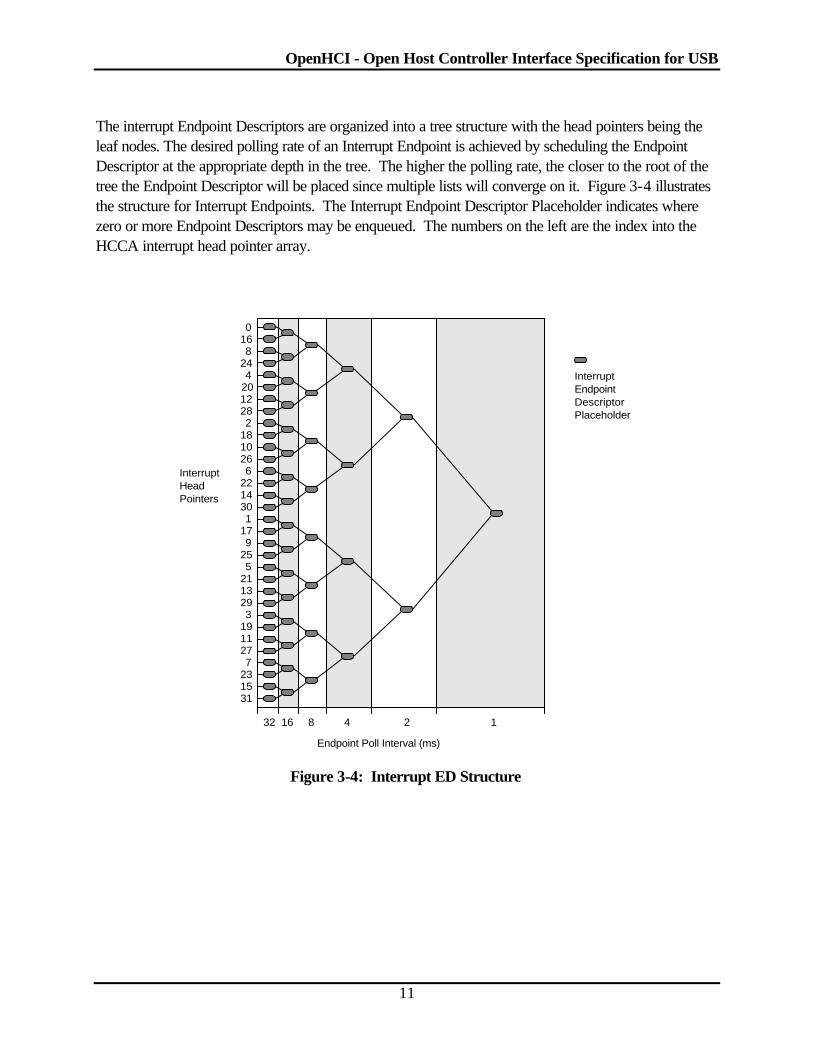
The interrupt Endpoint Descriptors are organized into a tree structure with the head pointers being the leaf nodes. The desired polling rate of an Interrupt Endpoint is achieved by scheduling the Endpoint Descriptor at the appropriate depth in the tree. The higher the polling rate, the closer to the root of the tree the Endpoint Descriptor will be placed since multiple lists will converge on it. Figure 3-4 illustrates the structure for Interrupt Endpoints. The Interrupt Endpoint Descriptor Placeholder indicates where zero or more Endpoint Descriptors may be enqueued. The numbers on the left are the index into the HCCA interrupt head pointer array.
0
17
8
1
2
3
4
5
6
7
9
10
11
12
13
14
15
16
24
20
28
18
26
22
30
25
21
29
19
27
23
31
32 16 8 4 2 1
InterruptEndpointDescriptorPlaceholder
InterruptHeadPointers
Endpoint Poll Interval (ms)
Figure 3-4: Interrupt ED Structure
OpenHCI - Open Host Controller Interface Specification for USB
12
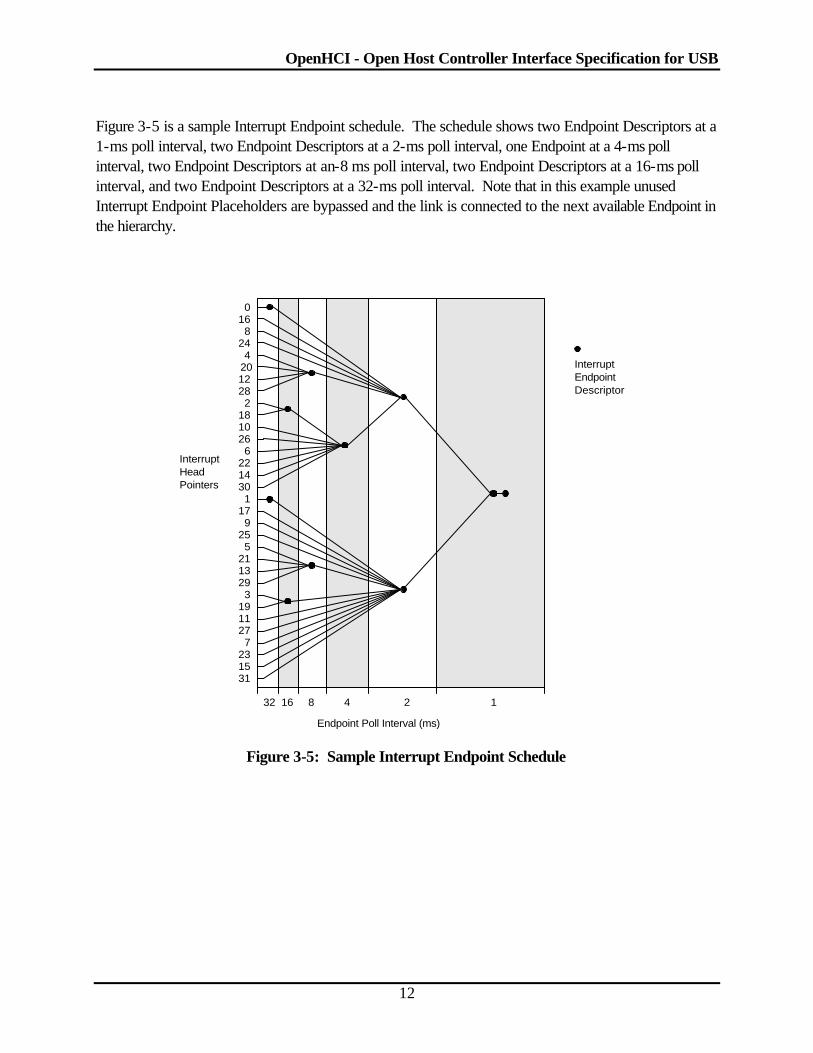
Figure 3-5 is a sample Interrupt Endpoint schedule. The schedule shows two Endpoint Descriptors at a 1-ms poll interval, two Endpoint Descriptors at a 2-ms poll interval, one Endpoint at a 4-ms poll interval, two Endpoint Descriptors at an-8 ms poll interval, two Endpoint Descriptors at a 16-ms poll interval, and two Endpoint Descriptors at a 32-ms poll interval. Note that in this example unused Interrupt Endpoint Placeholders are bypassed and the link is connected to the next available Endpoint in the hierarchy.
0
17
8
1
2
3
4
5
6
7
9
10
11
12
13
14
15
16
24
20
28
18
26
22
30
25
21
29
19
27
23
31
32 16 8 4 2 1
Endpoint Poll Interval (ms)
InterruptHeadPointers
InterruptEndpointDescriptor
Figure 3-5: Sample Interrupt Endpoint Schedule

OpenHCI - Open Host Controller Interface Specification for USB
13
3.4 Host Controller Driver Responsibilities This section summarizes the Host Controller Driver (HCD) responsibilities.
3.4.1 Host Controller Management The Host Controller Driver manages the operation of the Host Controller (HC). It does so by communicating directly to the operational registers in the Host Controller and establishing the interrupt Endpoint Descriptor list head pointers in the HCCA. The Host Controller Driver maintains the state of the HC, list processing pointers, list processing enables, and interrupt enables.
3.4.2 Bandwidth Allocation All access to the USB is scheduled by the Host Controller Driver. The Host Controller Driver allocates a portion of the available bandwidth to each periodic endpoint. If sufficient bandwidth is not available, a newly-connected periodic endpoint will be denied access to the bus. A portion of the bandwidth is reserved for nonperiodic transfers. This ensures that some amount of bulk and control transfers will occur in each frame period. The frame period is defined for USB to be 1.0 ms. The bandwidth allocation policy for OpenHCI is shown in Figure 3-6. Each frame begins with the Host Controller sending the Start of Frame (SOF) synchronization packet to the USB bus. This is followed by the Host Controller servicing nonperiodic transfers until the frame interval counter reaches the value set by the Host Controller Driver, indicating that the Host Controller should begin servicing periodic transfers. After the periodic transfers complete, any remaining time in the frame is consumed by servicing nonperiodic transfers once more.
1.0 ms
SOF NP Periodic NP
Time
Figure 3-6: Frame Bandwidth Allocation

OpenHCI - Open Host Controller Interface Specification for USB
14
3.4.3 List Management The transport mechanism for USB data packets is via Transfer Descriptor queues linked to Endpoint Descriptor lists. The Host Controller Driver creates these data structures then passes control to the Host Controller for processing. The Host Controller Driver is responsible for enqueuing and dequeuing Endpoint Descriptors. Enqueuing is done by adding the Endpoint Descriptor to the tail of the appropriate list. This may occur simultaneously with the Host Controller processing the list without requiring any lock mechanism. Before dequeuing an Endpoint Descriptor, the Host Controller Driver may disable the Host Controller from processing the entire Endpoint Descriptor list of the data type being removed to ensure that the Host Controller is not accessing the Endpoint Descriptor. The Host Controller Driver is also responsible for enqueuing Transfer Descriptors to the appropriate Endpoint Descriptor. Enqueuing is done by adding the Transfer Descriptor to the tail of the appropriate queue. This may occur simultaneously to the Host Controller processing the queue without requiring any lock mechanism. Under normal operation, the Host Controller dequeues the Transfer Descriptor. However, the Host Controller Driver dequeues the Transfer Descriptor when the Transfer Descriptor is being canceled due to a request from the client software or certain error conditions. In this instance, the Endpoint Descriptor is disabled prior to the Transfer Descriptor being dequeued.
3.4.4 Root Hub The Root Hub is integrated into the HC. The internal registers of the Root Hub are exposed to the Host Controller Driver which is responsible for providing the proper hub-class protocol with the USB Driver and proper control of the Root Hub.
3.5 Host Controller Responsibilities This section summarizes the Host Controller (HC) responsibilities.
3.5.1 USB States There are four USB states defined in OpenHCI: UsbOperational, UsbReset, UsbSuspend, and UsbResume. The Host Controller puts the USB bus in the proper operating mode for each state.

OpenHCI - Open Host Controller Interface Specification for USB
15
3.5.2 Frame management The Host Controller keeps track of the current frame counter and the frame period. At the beginning of each frame, the Host Controller generates the Start of Frame (SOF) packet on the USB bus and updates the frame count value in system memory. The Host Controller also determines if enough time remains in the frame to send the next data packet.
3.5.3 List Processing The Host Controller operates on the Endpoint Descriptors and Transfer Descriptors enqueued by the Host Controller Driver. For interrupt and isochronous transfers, the Host Controller begins at the Interrupt Endpoint Descriptor head pointer for the current frame. The list is traversed sequentially until one packet transfer from the first Transfer Descriptor of all interrupt and isochronous Endpoint Descriptors scheduled in the current frame is attempted. For bulk and control transfers, the Host Controller begins in the respective list where it last left off. When the Host Controller reaches the end of a list, it loads the value from the head pointer and continues processing. The Host Controller processes n control transfers to 1 bulk transfer where the value of n is set by the Host Controller Driver.
When a Transfer Descriptor completes, either successfully or due to an error condition, the Host Controller moves it to the Done Queue. Enqueuing on the Done Queue occurs by placing the most recently completed Transfer Descriptor at the head of the queue. The Done Queue is transferred periodically from the Host Controller to the Host Controller Driver via the HCCA.

OpenHCI - Open Host Controller Interface Specification for USB
16
4. DATA STRUCTURES 4.1 Overview
USB does not provide a mechanism for attached devices to arbitrate for use of the bus. As a consequence, arbitration for use of the interface is ‘predictive’ with the Host Controller (HC) and Host Controller Driver (HCD) software assigned the responsibility of providing service to devices when it is predicted that a device will need it. USB by necessity supports a number of different communications models between software and Endpoints (Bulk, Control, Interrupt, and Isochronous). Usage of the bus varies widely among these service classes, making the task of the host fairly challenging. The approach used by OpenHCI is to have two levels of arbitration to select among the endpoints. The first level of arbitration is at the list level. Each endpoint type needing service is in a list of a corresponding type (e.g., Isochronous Endpoints are in the isochronous list) and the Host Controller selects which list to service. Within a list, endpoints are given equal priority ensuring that all endpoints of a certain type have more-or-less equal service opportunities. The list priorities are modified at periodic intervals as endpoints are serviced. In each frame, an interval of time is reserved for processing items in the control and bulk lists. This interval is at the beginning of each frame. The Host Controller Driver limits this time by setting HcPeriodicStart with a bit time in a frame after which periodic transfers (interrupt and isochronous) have priority for use of the bus. During periodic list processing, the interrupt list specific to the current frame is serviced before the isochronous list. When processing of the periodic lists is complete, processing of the control and bulk lists can resume. An Endpoint Descriptor (ED) contains information about an endpoint that is used by the Host Controller to manage access to the endpoint. The endpoint’s address, transfer speed, and maximum data packet size are typical parameters which are kept in the ED. Additionally, the ED is used as an anchor for a queue of Transfer Descriptors. A Transfer Descriptor (TD) is attached to an ED define a memory buffer to/from which data is to be transferred for the endpoint. When the Host Controller accesses an ED and finds a valid TD address, the Host Controller completes a single transaction with the endpoint identified in the ED from/to the memory address indicated by the TD. When all of the data defined by a TD has been transferred, the TD is unlinked from its ED and linked to the done queue. The Host Controller Driver then processes the done queue and provides completion information to the software that originated the transfer request.

OpenHCI - Open Host Controller Interface Specification for USB
17
Details of the memory data structures that are processed by the Host Controller in support of the mechanisms described above are provided in the remainder of this chapter. Since the structures defined are all in system memory, the Host Controller Driver has full read-write access to all portions of the structures. The fields in the structures that are modified by the Host Controller are noted in the field descriptions. Fields that are indicated as being written by the Host Controller may not be modified by system software when the structure containing that field is on a queue or list that is being processed by the HC. No hardware interlocks are used to provide exclusion.
4.2 Endpoint Descriptor An Endpoint Descriptor (ED) is a 16-byte, memory resident structure that must be aligned to a 16-byte boundary. The Host Controller traverses lists of EDs and if there are TDs linked to an ED, the Host Controller performs the indicated transfer.
4.2.1 Endpoint Descriptor Format 3 2 1 1 1 1 1 1 1 0 0 0 0 0 0 0 0 1 6 6 5 4 3 2 1 0 7 6 5 4 3 2 1 0
Dword 0 — MPS F K S D EN FA Dword 1 TD Queue Tail Pointer (TailP) — Dword 2 TD Queue Head Pointer (HeadP) 0 C H Dword 3 Next Endpoint Descriptor (NextED) —
Figure 4-1: Endpoint Descriptor
Notes: 1. Fields containing ‘—’ are not interpreted or modified by the Host Controller and are available for
use by the Host Controller Driver for any purpose. 2. Fields containing ‘0’ must be written to 0 by the Host Controller Driver before queued for Host
Controller processing. If Host Controller has write access to the field, it will always write the field to 0.

OpenHCI - Open Host Controller Interface Specification for USB
18
4.2.2 Endpoint Descriptor Field Definitions
Table 4-1: Field Definitions for Endpoint Descriptor
Name
HC Access
Description
FA R FunctionAddress This is the USB address of the function containing the endpoint that this ED controls
EN R EndpointNumber This is the USB address of the endpoint within the function
D R Direction This 2-bit field indicates the direction of data flow (IN or OUT.) If neither IN nor OUT is specified, then the direction is determined from the PID field of the TD. The encoding of the bits of this field are:
Code Direction 00b Get direction From TD 01b OUT 10b IN 11b Get direction From TD
S R Speed Indicates the speed of the endpoint: full-speed (S = 0) or low-speed (S = 1.)
K R sKip When this bit is set, the HC continues on to the next ED on the list without attempting access to the TD queue or issuing any USB token for the endpoint
F R Format This bit indicates the format of the TDs linked to this ED. If this is a Control, Bulk, or Interrupt Endpoint, then F = 0, indicating that the General TD format is used. If this is an Isochronous Endpoint, then F = 1, indicating that the Isochronous TD format is used.
MPS R MaximumPacketSize This field indicates the maximum number of bytes that can be sent to or received from the endpoint in a single data packet
TailP R TDQueueTailPointer If TailP and HeadP are the same, then the list contains no TD that the HC can process. If TailP and HeadP are different, then the list contains a TD to be processed.
H R/W Halted This bit is set by the HC to indicate that processing of the TD queue on the endpoint is halted, usually due to an error in processing a TD.
C R/W toggleCarry This bit is the data toggle carry bit. Whenever a TD is retired, this bit is written to contain the last data toggle value (LSb of data Toggle field) from the retired TD. This field is not used for Isochronous Endpoints
HeadP
R/W TDQueueHeadPointer Points to the next TD to be processed for this endpoint.
NextED R NextED If nonzero, then this entry points to the next ED on the list

OpenHCI - Open Host Controller Interface Specification for USB
19
4.2.3 Endpoint Descriptor Description Endpoint Descriptors (ED) are linked in lists that are processed by the HC. An ED is linked to a next ED when the NextED field is nonzero. When the Host Controller accesses an ED, it checks the sKip and the Halted bits to determine if any further processing of the ED is allowed. If either bit is set, then the Host Controller advances to the next ED on the list. If neither the sKip nor the Halted bit is set, then the Host Controller compares HeadP to TailP. If they are not the same, then the TD pointed to by HeadP defines a buffer to/from which the Host Controller will transfer a data packet. This linking convention assumes that the Host Controller Driver queues to the ‘tail’ of the TD queue. It does this by linking a new TD to the TD pointed to by TailP and then updating TailP to point to the TD just added. When processing of a TD is complete, the Host Controller ‘retires’ the TD by unlinking it from the ED and linking it to the Done Queue. When a TD is unlinked, NextTD of the TD is copied to HeadP of the ED. The sKip bit is set and cleared by the Host Controller Driver when it wants the Host Controller to skip processing of the endpoint. This may be necessary when the Host Controller Driver must modify the value of HeadP and the overhead of removing the ED from its list is prohibitive. The Halted bit is set by the Host Controller when it encounters an error in processing a TD. When the TD in error is moved to the Done Queue, the Host Controller updates HeadP and sets the Halted bit, causing the Host Controller to skip the ED until Halted is cleared. The Host Controller Driver clears the Halted bit when the error condition has been corrected and transfers to/from the endpoint should resume. The Host Controller Driver should not write to HeadP/toggleCarry/Halted unless Halted is set, sKip is set, or the ED has been removed from the list. When TDs are queued to an ED, the Host Controller processes the TDs asynchronously with respect to processing by the host processor. Therefore, if the Host Controller Driver needs to alter the TD queue other than appending to the queue, it must stop the Host Controller from processing the TD queue for the endpoint so that changes can be made. The nominal mechanisms for stopping TD processing are for the Host Controller Driver to remove the ED from the list or to set the sKip bit in the ED. When the D field of an ED is 10b (IN), the Host Controller may issue an IN token to the specified endpoint after it determines that HeadP and TailP are not the same. This indicates that a buffer exists for the data and that input of the endpoint data may occur in parallel with the HC’s access of the TD which defines the memory buffer.

OpenHCI - Open Host Controller Interface Specification for USB
20
Since an ED must be aligned to a 16-byte boundary, the Host Controller only uses the upper 28 bits of Dword3 as a pointer to the next ED. TailP and HeadP point to TDs which may be either 16- or 32-byte aligned. The Host Controller uses only the upper 28 bits of Dword1 and Dword2 to point to a 16-byte aligned TD (F = 0). If HeadP and TailP point to a TD that must be 32-byte aligned (F = 1), then bit 4 of these Dwords must be 0.
4.3 Transfer Descriptors A Transfer Descriptor (TD) is a system memory data structure that is used by the Host Controller to define a buffer of data that will be moved to or from an endpoint. TDs come in two types: general and isochronous. The General TD is used for Interrupt, Control, and Bulk Endpoints and an Isochronous TD is used to deal with the unique requirements of isochronous transfers. Two TD types are supported because the nature of isochronous transfers does not lend itself to the standard DMA buffer format and the packetizing of the buffer required for isochronous transfers is too restrictive for general transfer types. Both the General TD and the Isochronous TD provide a means of specifying a buffer that is from 0 to 8,192 bytes long. Additionally, the data buffer described in a single TD can span up to two physically disjoint pages. Although the scatter/gather capabilities of a single TD are limited, it eliminates most of the problems associated with forcing buffers to be physically contiguous including the possibility of superfluous data movements. Transfer Descriptors are linked to queues attached to EDs. The ED provides the endpoint address to/from which the TD data is to be transferred. The Host Controller Driver adds to the queue and the Host Controller removes from the queue. When the Host Controller removes a TD from a queue, it links the TD to the Done Queue. When a TD is unlinked from the ED and linked to the Done Queue, it is said to be ‘retired’. A TD may be retired due to normal completion or because of an error condition. When the TD is retired, a condition code value is written in the TD which allows the Host Controller Driver to determine the reason it was retired. Details of TD processing are dependent on the type of TD and are discussed in Sections 4.3.1 through 4.3.3.1.
4.3.1 General Transfer Descriptor Transfers for control, bulk, and interrupt all use the same format for their Transfer Descriptor (TD). This General TD is a 16-byte, host memory structure that must be aligned to a 16-byte boundary.

OpenHCI - Open Host Controller Interface Specification for USB
21
4.3.1.1 General Transfer Descriptor Format 3 2 2 2 2 2 2 2 2 1 1 0 0 1 8 7 6 5 4 3 1 0 9 8 3 0
Dword 0 CC EC T DI DP R — Dword 1 Current Buffer Pointer (CBP) Dword 2 Next TD (NextTD) 0 Dword 3 Buffer End (BE)
Figure 4-2: General TD Format
Note: In Dword0, there are fields that are read/write by the HC. The unused portion of this Dword (indicated by ‘—’ ) must either not be written by Host Controller or must be read, and then written back unmodified. The Host Controller Driver should not modify any portion of the TD while it is accessible to the HC.
4.3.1.2 General Transfer Descriptor Field Definitions
Table 4-2: Field Definitions for General TD
Name
HC Access
Description
R R bufferRounding If this bit is 0, then the last data packet to a TD from an endpoint must exactly fill the defined data buffer. If the bit is 1, then the last data packet may be smaller than the defined buffer without causing an error condition on the TD.
DP R Direction/PID This 2-bit field indicates the direction of data flow and the PID to be used for the token. This field is only relevant to the HC if the D field in the ED was set to 00b or 11b indicating that the PID determination is deferred to the TD. The encoding of the bits within the byte for this field are:
PID Data Code Type Direction 00b SETUP to endpoint 01b OUT to endpoint 10b IN from endpoint 11b Reserved
DI R DelayInterrupt This field contains the interrupt delay count for this TD. When a TD is complete the HC may wait for DelayInterrupt frames before generating an interrupt. If DelayInterrupt is 111b, then there is no interrupt associated with completion of this TD.

OpenHCI - Open Host Controller Interface Specification for USB
22
Table 4-2: Field Definitions for General TD
Name
HC Access
Description
T R/W DataToggle This 2-bit field is used to generate/compare the data PID value (DATA0 or DATA1). It is updated after each successful transmission/reception of a data packet. The MSb of this field is ‘0’ when the data toggle value is acquired from the toggleCarry field in the ED and ‘1’ when the data toggle value is taken from the LSb of this field.
EC R/W ErrorCount For each transmission error, this value is incremented. If ErrorCount is 2 and another error occurs, the error type is recorded in the ConditionCode field and placed on the done queue. When a transaction completes without error, ErrorCount is reset to 0.
CC R/W ConditionCode This field contains the status of the last attempted transaction. (See Section 0.)
CBP R/W CurrentBufferPointer Contains the physical address of the next memory location that will be accessed for transfer to/from the endpoint. A value of 0 indicates a zero-length data packet or that all bytes have been transferred.
NextTD R/W NextTD This entry points to the next TD on the list of TDs linked to this endpoint
BE R BufferEnd Contains physical address of the last byte in the buffer for this TD
4.3.1.3 General Transfer Descriptor Description
4.3.1.3.1 Buffer Address Determination
The CurrentBufferPointer value in the General TD is the address of the data buffer that will be used for a data packet transfer to/from the endpoint addressed by the ED. When the transfer is completed without an error of any kind, the Host Controller advances the value of CurrentBufferPointer by the number of bytes transferred If during the data transfer the buffer address contained in the HC’s working copy of CurrentBufferPointer crosses a 4K boundary, the upper 20 bits of Buffer End are copied to the working value of CurrentBufferPointer causing the next buffer address to be the 0th byte in the same 4K page that contains the last byte of the buffer (the 4K boundary crossing may occur within a data packet transfer.)
4.3.1.3.2 Packet Size
For writes from the Host Controller to an endpoint (OUT and SETUP), the size of the data packet that is sent to an endpoint is always the smaller of MaximumPacketSize and the remaining data in the buffer. For reads from the endpoint to the Host Controller (IN), the size of the data packet is determined by the endpoint.

OpenHCI - Open Host Controller Interface Specification for USB
23
4.3.1.3.3 Condition Codes
The ConditionCode field of a General TD is updated after every attempted transaction, whether successful or not. If the transaction was successful, then the ConditionCode field is set to NOERROR. Otherwise, it is set according to the error type.
4.3.1.3.4 Sequence Bits
The USB protocol uses data PID sequencing to ensure that data packets are received in the correct order. The sequencing requires that the data transmitter continue to send the same data packet with the same data PID (either DATA0 or DATA1) until it has determined that the data packet has been successfully received and accepted. Reception and acceptance are indicated when the transmitter receives an ACK handshake after sending a data packet. In order to ensure that data packets are not lost, the Host Controller and the endpoint must start and stay in data toggle synchronization. Data toggle synchronization is first established at endpoint initialization with the nominal value for the first packet to/from an endpoint using DATA0. On each successive successful packet transmission/reception, the data toggle changes. The data toggle is maintained within a General TD simply by alternating the LSb of the dataToggle field. When the data toggle value must be carried between two General TDs, the toggleCarry bit in the ED is used to propagate the correct value to the next General TD. When the MSb of the dataToggle field is 0, that means that the value of the data toggle is obtained from the toggleCarry bit in the ED and the LSb of the dataToggle field is ignored. When the MSb of the dataToggle field is 1, then the LSb of the dataToggle field contains the value that is to be used for the data toggle. For bulk and interrupt endpoints, most General TDs are queued with dataToggle = 00b. This allows the data toggle to be carried across multiple TDs with the ED containing the value to be used for the first data packet in each transfer. After the first data packet is successfully transferred, the MSb of dataToggle is set to indicate that, for the remainder of the transfer, the dataToggle field will determine the data toggle and the LSb will be set to indicate the next toggle value. When the General TD is retired and HeadP in the ED is updated, the toggleCarry bit in the ED is written to indicate the data toggle value that will be used on the next packet for the endpoint.

OpenHCI - Open Host Controller Interface Specification for USB
24
For control endpoints, the convention is that the Setup packet will always use a data PID of DATA0, the first data packet will use a data PID of DATA1, and the Status packet will use a data PID of DATA1. Since this sequence does not rely on any previous data toggle history, the Setup, data, and status packets should be queued with the MSb of the dataToggle field = 1 and the LSb of each TD set appropriately (Setup = 0; Status = 1; and first data, if any, = 1.) Although the Host Controller updates the toggleCarry bit in the ED whenever a General TD is retired, the data toggle is determined solely by the General TD. The data toggle field of a General TD is advanced after every successful data packet transaction with the endpoint, including the last. As long as an ACK is sent (IN) or received (OUT or Setup), the data toggle will advance, even if other error conditions are encountered.
4.3.1.3.5 Transfer Completion
A transfer is completed when the Host Controller successfully transfers, to or from an endpoint, the byte pointed to by BufferEnd. Upon successful completion, the Host Controller sets CurrentBufferPointer to zero, sets ConditionCode to NOERROR, and retires the General TD to the Done Queue. The transfer may also complete when a data packet from an endpoint does not fill the buffer and is less than Maximum Packet Size bytes in length. In this case, CurrentBufferPointer is updated to point to the memory byte immediately after the last byte written to memory. Then, if the bufferRounding bit in the General TD is set, then this condition is treated as a normal completion and the Host Controller sets the ConditionCode field to NOERROR and retires the General TD to the Done Queue. If the bufferRounding bit in the General TD is not set, then this condition is treated as an error and the Host Controller sets the ConditionCode field to DATAUNDERRUN and the Halted bit of the ED is set as the General TD is retired.
4.3.1.3.6 Transfer Errors
There are several types of transfer errors that must be handled by the HC. They fall into the following categories: ?? transmission ?? sequence ?? system Transmission errors are errors that occur in communicating information over the USB wires and manifest themselves as CRC errors, BITSTUFFING errors, DEVICENOTRESPONDING errors. Sequence errors occur when the number of data bytes received does not match the number of bytes expected from an endpoint. System errors occur when the Host Controller has a problem resulting from the HC’s system environment that cannot otherwise be attributed to USB.

OpenHCI - Open Host Controller Interface Specification for USB
25
4.3.1.3.6.1 Transmission Errors
For errors in this category, USB defines a policy that allows the transaction to be retried for up to three times before the transfer is failed and returned to the client. The Host Controller supports this policy with the ErrorCount field. This field is initialized to 0 by the Host Controller Driver when the General TD is queued. This field is updated after each transaction attempt. If there is no transmission error, the field is written to 0. If, however, there is a transmission error, the field is incremented. If the ErrorCount field reaches 2 (10b) and another transmission error occurs (the third error in a row), the TD is retired to the Done Queue and the endpoint is halted. Data toggle mismatches on input data are counted as transmission errors. The cause of a data toggle mismatch is either failure of the endpoint to receive an ACK or a broken device. Data received when the data toggle mismatches is discarded and never written to host memory. An error in the PID check field is counted as a transmission error and is reported with a ConditionCode of PIDCHECKFAILURE.
4.3.1.3.6.2 Sequence Errors
Sequence errors occur only on reads from an endpoint to the Host Controller (IN). Sequence errors are not checked unless the data packet is received without a transmission error. There are two types of sequence errors: data overrun and data underrun. When either of these error conditions is encountered, the ConditionCode field is set accordingly, the General TD is retired, and the endpoint is halted. A data overrun error occurs when the number of bytes received from an endpoint exceeds either Maximum Packet Size or the number of bytes remaining in a General TD’s buffer. In the case of an overrun condition, the Host Controller writes to memory all of the data received up to the point where the data overrun condition was created. When the General TD is retired, CurrentBufferPointer points to the start of the data packet in error; however, all of the data bytes are valid and the data toggle will have advanced. The second type of sequence error, data underrun, occurs when the number of data bytes received from an endpoint is less than allowed. Even though a General TD is always retired when the number of bytes received from an endpoint is less than Maximum Packet Size, it does not always create an error condition. If the amount of received data fills the buffer exactly (last byte of a data packet written to BufferEnd), then a normal completion condition exists regardless of the size of the data packet. The General TD is retired with a ConditionCode of NOERROR and the endpoint is not halted. If the data packet does not fill the buffer exactly, the bufferRounding bit determines how the General TD will be retired. If the bufferRounding bit is not set, then the underrun is treated as an error condition. The ConditionCode field is set to DATAUNDERRUN, the General TD retired, and the endpoint is halted. If the bufferRounding field is set, then the General TD is retired without error. This condition is differentiated from a buffer-filled completion condition by CurrentBufferPointer not being zero when

OpenHCI - Open Host Controller Interface Specification for USB
26
the General TD is retired.

OpenHCI - Open Host Controller Interface Specification for USB
27
4.3.1.3.6.3 System Errors
For General TDs, system error sources are limited. In particular, an OpenHCI Host Controller will never have an overrun or underrun of its internal buffering for a General TD. An OpenHCI Host Controller is not allowed to issue an IN to an endpoint unless there is sufficient buffer space within the Host Controller to accept a data packet of Maximum Packet Size from the endpoint (64 bytes for a General TD) without having to access system memory. Similarly, the Host Controller is not allowed to issue an OUT or SETUP token unless it has pre-fetched to an internal buffer all the data that is sent to the endpoint in the data phase.
4.3.1.3.7 Special Handling
4.3.1.3.7.1 NAK
When an endpoint returns a NAK handshake, all General TD fields remain the same after the transaction as they were when the transaction began. The Host Controller makes no changes.
4.3.1.3.7.2 Stall
If an endpoint returns a STALL PID, the Host Controller retires the General TD with the ConditionCode set to STALL and halts the endpoint. The CurrentBufferPointer, ErrorCount, and dataToggle fields retain the values that they had at the start of the transaction.
4.3.2 Isochronous Transfer Descriptor An Isochronous TD is used exclusively for isochronous endpoints. All TDs linked to an ED with F = 1 must use this format. This 32-byte structure must be aligned to a 32-byte boundary in system memory.
4.3.2.1 Isochronous Transfer Descriptor Format 3 2 2 2 2 2 2 2 1 1 1 1 0 0 0 1 8 7 6 4 3 1 0 6 5 2 1 5 4 0
Dword 0 CC – FC DI — SF Dword 1 Buffer Page 0 (BP0) — Dword 2 NextTD 0 Dword 3 Buffer End (BE) Dword 4 Offset1/PSW1 Offset0/PSW0 Dword 5 Offset3/PSW3 Offset2/PSW2 Dword 6 Offset5/PSW5 Offset4/PSW4 Dword 7 Offset7/PSW7 Offset6/PSW6
Figure 4-3: Isochronous TD Format
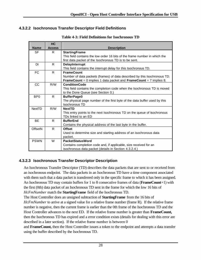
OpenHCI - Open Host Controller Interface Specification for USB
28
4.3.2.2 Isochronous Transfer Descriptor Field Definitions
Table 4-3: Field Definitions for Isochronous TD
Name
HC Access
Description
SF R StartingFrame This field contains the low order 16 bits of the frame number in which the first data packet of the Isochronous TD is to be sent.
DI R DelayInterrupt This field contains the interrupt delay for this Isochronous TD.
FC R FrameCount Number of data packets (frames) of data described by this Isochronous TD. FrameCount = 0 implies 1 data packet and FrameCount = 7 implies 8.
CC R/W ConditionCode This field contains the completion code when the Isochronous TD is moved to the Done Queue (see Section 0.)
BP0 R BufferPage0 The physical page number of the first byte of the data buffer used by this Isochronous TD
NextTD R/W NextTD This entry points to the next Isochronous TD on the queue of Isochronous TDs linked to an ED
BE R BufferEnd Contains the physical address of the last byte in the buffer.
OffsetN R Offset Used to determine size and starting address of an isochronous data packet.
PSWN W PacketStatusWord Contains completion code and, if applicable, size received for an isochronous data packet (details in Section 4.3.2.4.)
4.3.2.3 Isochronous Transfer Descriptor Description
An Isochronous Transfer Descriptor (TD) describes the data packets that are sent to or received from an isochronous endpoint. The data packets in an Isochronous TD have a time component associated with them such that a data packet is transferred only in the specific frame to which it has been assigned. An Isochronous TD may contain buffers for 1 to 8 consecutive frames of data (FrameCount+1) with the first (0th) data packet of an Isochronous TD sent in the frame for which the low 16 bits of HcFmNumber match the StartingFrame field of the Isochronous TD. The Host Controller does an unsigned subtraction of StartingFrame from the 16 bits of HcFmNumber to arrive at a signed value for a relative frame number (frame R). If the relative frame number is negative, then the current frame is earlier than the 0th frame of the Isochronous TD and the Host Controller advances to the next ED. If the relative frame number is greater than FrameCount, then the Isochronous TD has expired and a error condition exists (details for dealing with this error are described in a later section). If the relative frame number is between 0 and FrameCount, then the Host Controller issues a token to the endpoint and attempts a data transfer using the buffer described by the Isochronous TD.
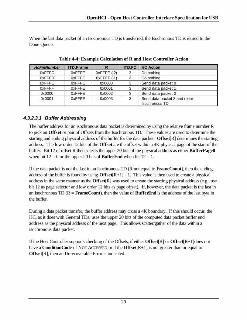
OpenHCI - Open Host Controller Interface Specification for USB
29
When the last data packet of an Isochronous TD is transferred, the Isochronous TD is retired to the Done Queue.
Table 4-4: Example Calculation of R and Host Controller Action
HcFmNumber ITD.Frame R ITD.FC HC Action 0xFFFC 0xFFFE 0xFFFE (-2) 3 Do nothing 0xFFFD 0xFFFE 0xFFFF (-1) 3 Do nothing 0xFFFE 0xFFFE 0x0000 3 Send data packet 0 0xFFFF 0xFFFE 0x0001 3 Send data packet 1 0x0000 0xFFFE 0x0002 3 Send data packet 2 0x0001 0xFFFE 0x0003 3 Send data packet 3 and retire
Isochronous TD
4.3.2.3.1 Buffer Addressing
The buffer address for an isochronous data packet is determined by using the relative frame number R to pick an Offset or pair of Offsets from the Isochronous TD. These values are used to determine the starting and ending physical address of the buffer for the data packet. Offset[R] determines the starting address. The low order 12 bits of the Offset are the offset within a 4K physical page of the start of the buffer. Bit 12 of offset R then selects the upper 20 bits of the physical address as either BufferPage0 when bit 12 = 0 or the upper 20 bits of BufferEnd when bit 12 = 1. If the data packet is not the last in an Isochronous TD (R not equal to FrameCount), then the ending address of the buffer is found by using Offset[R+1] - 1. This value is then used to create a physical address in the same manner as the Offset[R] was used to create the starting physical address (e.g., use bit 12 as page selector and low order 12 bits as page offset). If, however, the data packet is the last in an Isochronous TD (R = FrameCount), then the value of BufferEnd is the address of the last byte in the buffer. During a data packet transfer, the buffer address may cross a 4K boundary. If this should occur, the HC, as it does with General TDs, uses the upper 20 bits of the computed data packet buffer end address as the physical address of the next page. This allows scatter/gather of the data within a isochronous data packet. If the Host Controller supports checking of the Offsets, if either Offset[R] or Offset[R+1]does not have a ConditionCode of NOT ACCESSED or if the Offset[R+1] is not greater than or equal to Offset[R], then an Unrecoverable Error is indicated.

OpenHCI - Open Host Controller Interface Specification for USB
30
4.3.2.3.2 Data Packet Size
The size of the data packet that is to be sent or expected to be received is determined by the computed address values and not by MaximumPacketSize in the ED. A check that the buffer described by the Offsets is less than or equal to MaximumPacketSize is not required. If Offset[R] and Offset[R+1] are the same, then a zero-length packet is indicated. For a zero-length OUT packet, the Host Controller issues a token and sends a zero length data packet. For a zero-length IN packet, the Host Controller issues a token and accepts a zero-length data packet from the endpoint.
4.3.2.3.3 Status
After each data packet transfer, the Rth Offset is replaced with a value that indicates the status of the data packet transfer. The upper 4 bits of the value are the ConditionCode for the transfer and the lower 12 bits represent the size of the transfer. Together, these two fields constitute the Packet Status Word (PacketStatusWord). After a data packet is transferred, the Host Controller sets both fields of the PacketStatusWord. For an OUT, in the absence of transfer errors, the size field is set to 0. For an IN, the size field indicates the actual number of bytes written to memory. In the absence of errors, this is also the number of bytes received from the endpoint.
4.3.2.3.4 Transfer Completion
An Isochronous TD is completed when all FrameCount+1 data packets have been transferred. In the frame when R = FrameCount, after the data transaction is complete and the Offset R updated, the ConditionCode of the Isochronous TD is set to NOERROR and the Isochronous TD is retired to the Done Queue.
4.3.2.3.5 Transfer Errors
Transfer errors for isochronous errors fall into four categories: ?? transmission ?? sequence ?? time ?? system

OpenHCI - Open Host Controller Interface Specification for USB
31
4.3.2.3.5.1 Transmission Errors
Since there is no handshake for isochronous transfers, the Host Controller can detect transmission errors for transfers only from an endpoint to the host (IN). The error may be either a CRC error, a BITSTUFFING error, or a DEVICENOTRESPONDING error. If any of these errors occurs during the transfer, the ConditionCode of PacketStatusWord[R] is set accordingly and the size field reflects the number of bytes received (up to the size of the buffer defined for the frame) and placed in the memory buffer. For a bit stuffing error, the Host Controller writes up only to the last byte received before the bit stuffing error is detected. If a transmission error is detected along with a sequence or system error, the transmission error is the one that is reported in the ConditionCode . A PID check error in the PID from an endpoint is reported with a ConditionCode of PIDCHECKFAILURE.
4.3.2.3.5.2 Sequence Errors
A sequence error occurs when the endpoint sends more or less data than is expected and a transmission error is not present. If the endpoint sends more data than will fit in the specified buffer, the ConditionCode for the PacketStatusWord is set to DATAOVERRUN and the size field is set to the size of the buffer. The Host Controller writes the received data to memory up to the limit of the buffer defined for the frame. If the endpoint sends less data than defined by the buffer, the ConditionCode for the PacketStatusWord is set to DATAUNDERRUN.
4.3.2.3.5.3 Time Errors
Each packet has a specific frame in which it is to be transferred. It is possible that the Host Controller cannot start or complete the transfer in the specified frame. There are two manifestations of this type of error: skipped packets and late retirement of an Isochronous TD. Skipped packets occur if the Host Controller does not process an Isochronous TD in a frame for which the Isochronous TD has data. A skipped packet is indicated when an Offset/PacketStatusWord is set to NOT ACCESSED after the Isochronous TD is retired. This indicates that the Host Controller did not process the Isochronous TD for the frame and therefore did not change the Offset to a PacketStatusWord. When the Host Controller skips the last packet of the Isochronous TD, a more significant error occurs. Since the Isochronous TD was not processed in the frame in which it should have been retired, the Isochronous TD remains on its ED’s queue. When the Host Controller processes the Isochronous TD in a latter frame, it finds that the time for expiration of the Isochronous TD has passed. In such cases, the Host Controller sets the ConditionCode for the Isochronous TD to DATAOVERRUN and retires the

OpenHCI - Open Host Controller Interface Specification for USB
32
Isochronous TD (it does not, however, set the Halted bit in the ED). The Host Controller then accesses the next Isochronous TD for the same ED and processes it.

OpenHCI - Open Host Controller Interface Specification for USB
33
Note: Setting DATAOVERRUN in the ConditionCode for the Isochronous TD rather than the
PacketStatusWord indicates a time overrun. The same code in a PacketStatusWord will indicate a true data buffer overrun.
Table 4-5: Example of Time Overrun
HcFmNumber ITD.Frame R ITD.FC HC Action 0xFFFC 0xFFFE 0xFFFE (-2) 3 Do nothing
0xFFFD 0xFFFE 0xFFFF (-1) 3 Do nothing 0xFFFE 0xFFFE 0x0000 3 Send data packet 0
Host Controller does not process Isochronous TD for three frames due to schedule overrun, then... 0x0002 0xFFFE 0x0004 3 Retire Isochronous TD with DATAOVERRUN
in ITD.CC
4.3.2.3.5.4 System Errors
The most probable source of system errors for isochronous transfers is underrun or overflow/overrun of the HC’s internal data buffers. An Isochronous TD is allowed to specify a single data packet of up to 1023 bytes. It is not expected that Host Controller implementations will contain sufficient internal buffering for the largest possible isochronous packet. Therefore, there is a possibility that the system will not provide timely access to the system bus to allow the Host Controller to keep up with the USB data rate in all cases. This can cause the HC’s internal buffer to overflow with data from an endpoint or to underrun and have no data to send to an endpoint when it is required. Buffer overrun happens only on IN endpoints and underrun happens only on OUT endpoints. When an underrun occurs, the Host Controller sets the ConditionCode of the data packet’s PacketStatusWord to BUFFERUNDERRUN and the size field is set to zero. Note: This underrun condition is signaled on USB by the Host Controller forcing a bit-stuffing violation
with the recommendation that the bit stuff violation last 16 bit times (i.e., 16 bit times without a transition on the bus).
When an overrun condition occurs, the Host Controller sets the ConditionCode of the data packet’s PacketStatusWord to BUFFEROVERRUN and writes the size field to indicate the last byte successfully received from the endpoint before the overrun condition occurred. All data received from the endpoint before the overrun condition occurred are stored in system memory. If, after detecting an overrun, the Host Controller detects a transmission error, then the transmission error is recorded in the PacketStatusWord instead of the overrun error.

OpenHCI - Open Host Controller Interface Specification for USB
34
4.3.2.3.6 Special Handling
4.3.2.3.6.1 NAK and STALL
NAK and STALL are not nominally supported by the isochronous protocol. If an isochronous endpoint returns either of these handshake packets during the data phase of an IN, the Host Controller writes the ConditionCode of the frames PacketStatusWord to STALL and sets the data size to 0. The Isochronous TD is not retired early and the endpoint is not halted.
4.3.2.4 PacketStatusWord
1 1 1 1 0 5 2 1 0 0
CC 0 SIZE
Figure 4-4: PacketStatusWord Format
4.3.2.4.1 Packet Status Word Field Definitions
Table 4-6: Field Definitions for Packet Status Word
Name R/W Description SIZE W Size of Packet
On an IN transfer, this 11-bit field is written to contain the number of bytes received from the endpoint. On an OUT, this field is written to 0.
CC W Condition Code Used both to indicate completion status and the format of the word. When the Condition Code indicates NOT ACCESSED, the data is in Offset format. Otherwise, the SIZE field contains a value that is appropriate to the direction of data flow and the completion status.

OpenHCI - Open Host Controller Interface Specification for USB
35
4.3.3 Completion Codes
Table 4-7: Completion Codes
Code Meaning Description 0000 NOERROR General TD or isochronous data packet processing
completed with no detected errors 0001 CRC Last data packet from endpoint contained a CRC error. 0010 BITSTUFFING Last data packet from endpoint contained a bit stuffing
violation 0011 DATATOGGLEMISMATCH Last packet from endpoint had data toggle PID that did not
match the expected value. 0100 STALL TD was moved to the Done Queue because the endpoint
returned a STALL PID 0101 DEVICENOTRESPONDING Device did not respond to token (IN) or did not provide a
handshake (OUT) 0110 PIDCHECKFAILURE Check bits on PID from endpoint failed on data PID (IN) or
handshake (OUT) 0111 UNEXPECTEDPID Receive PID was not valid when encountered or PID value is
not defined. 1000 DATAOVERRUN The amount of data returned by the endpoint exceeded
either the size of the maximum data packet allowed from the endpoint (found in MaximumPacketSize field of ED) or the remaining buffer size.
1001 DATAUNDERRUN The endpoint returned less than MaximumPacketSize and that amount was not sufficient to fill the specified buffer
1010 reserved 1011 reserved 1100 BUFFEROVERRUN During an IN, HC received data from endpoint faster than it
could be written to system memory 1101 BUFFERUNDERRUN During an OUT, HC could not retrieve data from system
memory fast enough to keep up with data USB data rate. 111x NOT ACCESSED This code is set by software before the TD is placed on a
list to be processed by the HC.

OpenHCI - Open Host Controller Interface Specification for USB
36
4.3.3.1 Condition Code Description
For General TDs, the condition codes in ConditionCode have meaning to software only if the General TD is on the Done Queue. For CRC, BITSTUFFING, and DEVICENOTRESPONDING errors, the General TD is not moved to the Done Queue unless errors are encountered in three successive accesses of the device (error does not have to be the same in all three attempts.) For STALL, DATAOVERRUN, or DATAUNDERRUN, the General TD is moved to the done queue on the first occurrence of the error. BUFFEROVERRUN or BUFFERUNDERRUN are not used for General TDs. When a General TD is moved to the done queue with the ConditionCode set to other than NOERROR, the Halted bit in the ED for the endpoint is set to halt processing of General TDs for the endpoint until software clears the error condition. For an Isochronous TD, condition codes appear in two places: in ConditionCode of Dword0 and in each of the Offset/PacketStatusWords . For each data packet processed, the Host Controller converts OffsetR into PSWR by setting the ConditionCode field. All condition codes are valid for a PacketStatusWord. The ConditionCode in Dword0 of the Isochronous TD is set when the TD is moved to the done queue. The Isochronous TD can be moved to the done queue when the last data packet is transferred (in which case the ConditionCode will be NOERROR) or due to the frame for the last data packet having passed (in which case the ConditionCode will be DATAOVERRUN.) In no case does the Host Controller set the Halted bit in the ED for an Isochronous TD. An Isochronous TD with a NOERROR ConditionCode may contain PacketStatusWords with ConditionCodes other than NOERROR.
4.4 Host Controller Communications Area The Host Controller Communications Area (HCCA) is a 256-byte structure of system memory that is used by system software to send and receive specific control and status information to and from the HC. This structure must be located on a 256-byte boundary. System software must write the address of this structure in HcHCCA in the HC. This structure allows the software to direct the HC’s functions without having to read from the Host Controller except in unusual circumstances (e.g., error conditions). Normal interaction with the Host Controller can be accomplished by reading values from this structure that were written by the Host Controller and by writing to the HC’s operation registers. Note: It is expected that writes to the Host Controller will be posted and have minimal impact on
CPU performance.

OpenHCI - Open Host Controller Interface Specification for USB
37
4.4.1 Host Controller Communications Area Format
Offset
Size (bytes)
Name
R/W
Description
0 128 HccaInterrruptTable R These 32 Dwords are pointers to interrupt EDs. 0x80 2 HccaFrameNumber W Contains the current frame number. This value is
updated by the HC before it begins processing the periodic lists for the frame.
0x82 2 HccaPad1 W When the HC updates HccaFrameNumber, it sets this word to 0.
0x84 4 HccaDoneHead
W When the HC reaches the end of a frame and its deferred interrupt register is 0, it writes the current value of its HcDoneHead to this location and generates an interrupt if interrupts are enabled. This location is not written by the HC again until software clears the WD bit in the HcInterruptStatus register. The LSb of this entry is set to 1 to indicate whether an unmasked HcInterruptStatus was set when HccaDoneHead was written.
0x88 116 reserved R/W Reserved for use by HC
Figure 4-5: Host Controller Communications Area Format
4.4.2 Host Controller Communications Area Description 4.4.2.1 HccaInterruptTable
HccaInterruptTable is a 32-entry table with each entry being a Dword. The table entries are pointers to an Interrupt List each of which is a list of EDs. Each ED then points to a queue of TDs for that endpoint. HccaInterruptTable is accessed once per frame by the HC. The low order 5 bits of the current frame number is used as an index into the table. An ED for an interrupt endpoint may appear on multiple Interrupt Lists. The more lists in which an ED is linked, the greater its polling rate. An ED that is in only one list has a polling rate of once every 32 ms. An ED that is on 2 lists has a polling rate of once every 16 ms. If an ED is linked into all 32 lists, then it has a polling rate of once per 1 ms or every frame. This list structure allows uniform polling only at intervals of 1, 2, 4, 8, 16, and 32 ms. A grouping of EDs with the same polling rate that occurs in the same frame is a sublist. The number of sublists at each polling rate is the same as the polling rate. For example, there can be two sublists with polling rates of 2 ms with each list being processed on alternate frames. The last entry in each of the 32 interrupt lists must point to the isochronous list.

OpenHCI - Open Host Controller Interface Specification for USB
38
4.4.2.2 HccaFrameNumber
This 16-bit value is updated by the Host Controller on each frame. This value is written with the StartingFrame field of HcFmNumber after the Host Controller has sent an SOF and before the Host Controller reads an ED for processing in the new frame. The Host Controller transfers no data on USB between the time it sends an SOF and the time it updates this memory location.
4.4.2.3 HccaDoneHead
When a TD is complete (with or without an error) it is unlinked from the queue that it is on and linked to the Done Queue. The Host Controller maintains a physical pointer to the last TD that was placed on the done queue (HcDoneHead.) When a TD is put on the done queue, the value in HcDoneHead is written to NextTD of the just completed TD and HcDoneHead is changed to contain the address of the TD just competed. This causes TDs to be linked at the head of the done queue. Linking at the head of the queue allows the hardware to maintain only one pointer for the Done Queue and also allows the linking to the Done Queue to be done at the same time as the ConditionCode update in a completed TD saving a memory access (i.e., the same write that updates the ConditionCode of a TD can be extended to cause the NextTD value of the TD to point to the TD that was previously at the head of the Done Queue.) Periodically, the Host Controller writes the current value of its HcDoneHead register into a memory location (HccaDoneHead) so that host software can process completed TDs. Nominally, HcDoneHead is written to memory at the beginning of a frame when the deferred interrupt count is zero. After HcDoneHead is written to HccaDoneHead, the Host Controller sets HcDoneHead to 0 and sets the WD bit in the HcInterruptStatus register. The Host Controller can begin to build a new Done Queue immediately after writing to HccaDoneHead but it cannot write the new list to memory until the Host Controller Driver has cleared the WD bit. This protocol provides an interlocked exchange of the Done Queue. The LSb of this value is used to inform the Host Controller Driver that an interrupt condition exists for both the done list and for another event recorded in the HcInterruptStatus register. On an interrupt from the HC, the Host Controller Driver checks the HccaDoneHead Value. If this value is 0, then the interrupt was caused by other than the HccaDoneHead update and the HcInterruptStatus register needs to be accessed to determine that exact interrupt cause. If HccaDoneHead is nonzero, then a done list update interrupt is indicated and if the LSb of the Dword is nonzero, then an additional interrupt event is indicated and HcInterruptStatus should be checked to determine its cause.
OpenHCI - Open Host Controller Interface Specification for USB
39
4.5 Endpoint List Processing The Host Controller schedules transfers to endpoints on USB based on the structure of the four endpoint lists: bulk, control, interrupt, and isochronous. For bulk and control, the Host Controller maintains a software- accessible pointer to the head of the list. For interrupt, 32 list heads are kept in memory with a list selected each frame. The isochronous list is linked to the end of all of the interrupt lists. In addition to the head pointers, the Host Controller maintains three software-accessible pointers to the current ED for control, bulk, and an additional pointer that is used for both periodic lists (interrupt and isochronous.) The Host Controller selects a list to process based on a priority algorithm. At the beginning of each frame, processing of the control and bulk list has priority until the HcFmRemaining counts down to the value in HcPeriodicStart. At that point, processing of the periodic lists has priority over control/bulk processing until either periodic list processing is complete or the frame time expires. While control and bulk have priority, the Host Controller alternates processing of EDs on each of the lists. The setting of the Control Bulk Ratio field in HcControl determines the ratio of the number of control to bulk transactions that will be attempted. If CB is set to 00b, then the Host Controller allows one bulk transaction for each control transaction. If CB = 11b, then the Host Controller allows one bulk transition after every 4 control transactions. If either the control or bulk lists is empty, then 100% of the control/bulk time is allocated to the list that is not empty. The control and bulk lists are considered empty if either no EDs are linked to the list (the head pointer in the Host Controller contains a zero) or if all the TD queues of the EDs on the list are empty. To detect this empty condition, the Host Controller maintains two bits: control-filled (CF) and bulk-filled (BF) in the HcCommandStatus register. When the Host Controller starts processing at the head of the control or bulk list, it clears the corresponding filled bit. When the Host Controller finds an ED in the control or bulk list with a TD to be processed, it sets the corresponding filled bit. When the Host Controller reaches the end of the list, it checks the filled bit. If it is zero, then the list is empty and processing of the list stops. When the Host Controller Driver makes an addition to either the control or bulk lists, it must write to the corresponding filled bit to ensure that the Host Controller continues to process the list.
OpenHCI - Open Host Controller Interface Specification for USB
40
4.6 Transfer Descriptor Queue Processing For a transfer to or from an endpoint to occur, a TD must be linked to the queue associated with the ED. HeadP and TailP in an ED define the TD queue. If HeadP and TailP are not the same, then HeadP is a pointer to the TD that will be processed when the Host Controller reaches the ED. Software queues to the list by using the value of TailP to obtain the physical address of the last TD queued to the ED. Since the TD pointed to by TailP is not accessed by the HC, the Host Controller Driver can initialize that TD and link at least one other to it without creating a coherency or synchronization problem. After the new TDs are linked, TailP is updated, extending the list of TDs that can be accessed and processed by the HC, with TailP again pointing to a TD that can be initialized by software. Software may not alter in any way any of the TDs it has queued prior to the one pointed to by TailP until the Host Controller completes processing of the TD or the Host Controller Driver ensures that queue processing for the ED has been halted. When the Host Controller finishes processing a TD, it copies the NextTD value from the just completed TD into HeadP of the ED. For a General TD, the Host Controller also sets the toggle Carry bit to the value of the last used data toggle for the endpoint and sets the Halted bit to 0 if the TD completed without error or to 1 if an error occurred.

OpenHCI - Open Host Controller Interface Specification for USB
41
5. HOST CONTROLLER DRIVER This section covers details of how the Host Controller Driver (HCD) interacts with the Host Controller Interface. Where necessary, this section goes into how the Host Controller Driver may be implemented in order to provide a clear understanding of how the software is intended to interact with the OpenHCI. The provided sample code is intended to illustrate the interaction between the software and the hardware and is not intended to be a complete driver implementation. Note that many simplifying assumptions have been made and many items that do not add to the reader’s understanding of the interaction between the software and the hardware are omitted. Two of the assumptions used for the samples are that the code is for a uniprocessor machine and that all the samples are run with the interrupts disabled. The Host Controller Driver is responsible for a per-Host Controller set of data called device data.
5.1 Host Controller Management The Host Controller (HC) is first managed through a set of Operational Registers. These registers exist in the Host Controller and are accessed using memory references via a noncached virtual pointer. All Host Controller Operational Registers start with the prefix Hc. Refer to Section 7, Operational Registers, for a complete definition of all the Hc registers. The HcHCCA is filled in by software and points the Host Controller at the block of shared RAM called the Host Controller Communication Area (HCCA). All fields within the HCCA start with the prefix Hcca. Refer to Section 4.4, Host Controller Communications Area , for a complete definition of all the Hccas.
5.1.1 Initialization There are a number of steps necessary for an OS to bring its Host Controller Driver to an operational state:
?? Load Host Controller Driver and locate the HC ?? Verify the HC and allocate system resources ?? Take control of HC (support for an optional System Management Mode driver) ?? Set up HC registers and HC Communications Area ?? Begin sending SOF tokens on the USB
Note: Due to some devices on the USB that may take a long time to reset, it is desirable that the Host Controller Driver startup process not transition to the USBRESET state if at all possible. The description of driver and controller initialization in following sections takes this into account.

OpenHCI - Open Host Controller Interface Specification for USB
42
OperationalRegisters
Mode
Host ControllerCommications Area
HCCA
Status
Event
Frame Int
Control
Interrupt 0
Interrupt 1
Interrupt 31
. . . Interrupt 2
Done
. . .
. . .
Bulk
Ratio
Shared RAM
OpenHCI
Device Enumeration
Device Registerin memory space
Figure 5-1: The OpenHCI Host Controller
5.1.1.1 Load and Locate
When the Host Controller Driver first loads, it locates the Host Controller and its operational registers through a process of Device Enumeration that is specific to both the operating system environment and the host bus on which the Host Controller resides.
5.1.1.2 Verify Host Controller and Allocate Resources
The Host Controller Driver checks the Revision field in the HcRevision register to verify the HC’s interface is compatible with the Host Controller Driver. When checking the Revision, the Host Controller Driver must mask the rest of the bits in the HcRevision register as they are used to specify which optional features that are supported by the HC. The Host Controller Driver then allocates and initializes any Host Controller structures, including the HCCA block, and operating system structures it needs. Upon success, the Host Controller Driver retains the noncached virtual address of the operation register block in its device data.

OpenHCI - Open Host Controller Interface Specification for USB
43
5.1.1.3 Take Control of Host Controller
OpenHCI allows for optional support of legacy devices through the use of System Management Mode software and System Management Interrupt hardware. In order to provide for this, a mechanism is defined to allow control of the Host Controller to be passed between the SMM driver and an OS driver; both of these drivers may properly be called an Host Controller Driver, but only one is active at any given time. Only the active Host Controller Driver is allowed to write to Host Controller registers or manipulate lists and queues, with the exception of writing the OwnershipChangeRequest bit to the HcCommandStatus register (only an OS driver does this). There is also another interesting case where the system vendor chooses not to emulate legacy devices but does wish to support USB devices in firmware (BIOS); in this case, System Management Mode is not used. The following cases are discussed separately in following sections:
?? Initialization of an SMM driver after a cold power-up ?? Initialization of a BIOS driver ?? Initialization of an OS driver when an SMM driver is active ?? Initialization of an OS driver when a BIOS driver is active ?? Initialization of an OS driver when neither an SMM nor a BIOS driver is active ?? Re-initialization of an SMM driver (control returned by an OS driver)
5.1.1.3.1 SMM Driver, Power-Up
The SMM driver gains control of the processor before any other driver; this means that the Host Controller will be in the state that it enters after a hardware reset (USBRESET). The SMM driver must set the InterruptRouting bit in the HcControl register. This causes all Host Controller interrupts to be routed to the SMI. Since the SMM driver is system-specific, if it has knowledge of proper settings for system-specific fields in the Host Controller registers, it should set those to their proper values at this time. These fields include: RemoteWakeupConnected in the HcControl register, FrameInterval and FSLargestDataPacket in the HcFmInterval register, PowerSwitchingMode and OverCurrentProtection in the HcRhDescriptorA register, and PowerOnToPowerGoodTime and RemovableDevice in the HcRhDescriptorB register. The driver should then wait at least the minimum time specified in the USB Specification for assertion of reset on the USB before it proceeds to the setup of the HC.
5.1.1.3.2 BIOS Driver
The BIOS driver is not expected to exist if there is an SMM driver (on a system with an SMM driver, the BIOS is expected to communicate its needs to the SMM driver in a system-specific manner). The BIOS driver gains control of the processor before any other driver, but the Host Controller may not be in the USBRESET state because this may be a warm boot. For the purpose of OpenHCI, a cold boot is defined as one in which the HostControllerFunctionalState in the HcControl register is found to be USBRESET.
OpenHCI - Open Host Controller Interface Specification for USB
44
On a cold boot, the BIOS driver should use the system-specific knowledge it has to initialize the system-specific fields in the Host Controller registers. These fields include: RemoteWakeupConnected in the HcControl register, FrameInterval and FSLargestDataPacket in the HcFmInterval register, PowerSwitchingMode and OverCurrentProtection in the HcRhDescriptorA register, and PowerOnToPowerGoodTime and RemovableDevice in the HcRhDescriptorB register. The driver should then wait at least the minimum time specified in the USB Specification for assertion of reset on the USB before it proceeds to the setup of the HC. On a warm boot, if the HostControllerFunctionalState is USBOPERATIONAL, then the BIOS driver should proceed directly to the setup of the HC. Otherwise, the BIOS driver should set the HostControllerFunctionalState to USBRESUME and wait the minimum time specified in the USB Specification for assertion of resume on the USB before it proceeds to the setup of the HC.
5.1.1.3.3 OS Driver, SMM Active
The OS driver knows that the SMM driver is active because the InterruptRouting bit is set in the HcControl register. The OS driver writes a one to the OwnershipChangeRequest bit in the HcCommandStatus; then it monitors the InterruptRouting bit to determine when the ownership change has taken effect. The SMM driver receives an Ownership Change interrupt; this causes the SMM driver to deconfigure all the devices it has configured on the USB, clear all interrupt masks, and disable all list processing. Finally, the SMM driver clears the InterruptRouting bit and returns control to the OS. Once the InterruptRouting bit is cleared, the OS driver may proceed to the setup of the HC.
5.1.1.3.4 OS Driver, BIOS Active
By examining the contents of the HcControl register, the OS driver knows there is an active BIOS driver if the InterruptRouting bit is not set and the HostControllerFunctionalState is not USBRESET. If the HostControllerFunctionalState is USBOPERATIONAL, then the OS driver should proceed directly to the setup of the HC. Otherwise, the OS driver should set the HostControllerFunctionalState to USBRESUME and wait the minimum time specified in the USB Specification for assertion of resume on the USB before it proceeds to the setup of the HC.
5.1.1.3.5 OS Driver, neither SMM nor BIOS
By examining the contents of the HcControl register, the OS driver knows that there is neither an SMM driver nor a BIOS driver if the InterruptRouting bit is not set and the HostControllerFunctionalState is USBRESET. The driver should then wait at least the minimum time specified in the USB Specification for assertion of reset on the USB before it proceeds to the setup of the Host Controller.

OpenHCI - Open Host Controller Interface Specification for USB
45
5.1.1.3.6 SMM Driver, Re-Entry
Occasionally, to provide compatibility with older applications, an OS may decide to return control of the Host Controller to the SMM driver. The OS driver should deconfigure all the devices on the USB, clear all interrupt masks, and disable all list processing. The OS driver should then write a one to the OwnershipChangeRequest bit in the HcCommandStatus register; this causes an Ownership Change interrupt using SMI. Upon servicing this interrupt, The SMM driver sets the InterruptRouting bit in the HcControl register and proceeds to the setup of the Host Controller.
5.1.1.4 Setup Host Controller
The Host Controller Driver should now save the contents of the HcFmInterval register and then issue a software reset by writing a one to the HostControllerReset bit in the HcCommandStatus register. After the software reset is complete (a maximum of 10 ? s), the Host Controller Driver should restore the value of the HcFmInterval register. The Host Controller is now in the USPSUSPEND state; it must not stay in this state more than 2 ms or the USBRESUME state will need to be entered for the minimum time specified in the USB Specification for the assertion of resume on the USB. The Host Controller Driver should perform the following initializations:
?? Initialize the device data HCCA block to match the current device data state; i.e., all virtual queues are run and constructed into physical queues on the HCCA block and other fields initialized accordingly.
?? Initialize the Operational Registers to match the current device data state; i.e., all virtual queues are run and constructed into physical queues for HcControlHeadED and HcBulkHeadED
?? Set the HcHCCA to the physical address of the HCCA block. ?? Set HcInterruptEnable to have all interrupt enabled except SOF detect. ?? Set HcControl to have “all queues on”. ?? Set HcPeriodicStart to a value that is 90% of the value in FrameInterval field of the
HcFmInterval register.
5.1.1.5 Begin Sending SOFs
The HCD then begins to send SOF tokens on the USB by writing to the HcControl register with the HostControllerFunctionalState set to USBOPERATIONAL and the appropriate enable bits set. The Host Controller begins sending SOF tokens within one ms (if the HCD needs to know when the SOFs it may unmask the StartOfFrame interrupt).

OpenHCI - Open Host Controller Interface Specification for USB
46
5.1.2 Operational States The operational states of the Host Controller are defined by their effect on the USB:
?? USBOPERATIONAL ?? USBRESET ?? USBRESUME ?? USBSUSPEND
5.1.2.1 USBRESET
When the Host Controller enters this state, most of the operational registers are ignored by the Host Controller and need not contain any meaningful values; however, the contents of the registers (except Root Hub registers) are preserved by the HC. The obvious exception is that the Host Controller uses the HcControl register which contains the HostControllerFunctionalState. While in this state, the Root Hub is being reset, which causes the Root Hub’s downstream ports to be reset and possibly powered off. This state must be maintained for the minimum time specified in the USB Specification for the assertion of reset on the USB. Only the following interrupts are possible while the Host Controller is in the USBRESET state: OwnershipChange.
5.1.2.2 USBOPERATIONAL
This is the normal state of the HC. In this state, the Host Controller is generating SOF tokens on the USB and processing the various lists that are enabled in the HcControl register. This allows the clients of the Host Controller Driver, USBD and above, to communicate with devices on the USB. The Host Controller generates the first SOF token within one ms of the time that the USBOPERATIONAL state is entered (if the Host Controller Driver wants to know when this occurs, it may enable the StartOfFrame interrupt). All interrupts are possible in the USBOPERATIONAL state, except ResumeDetected.
5.1.2.3 USBSUSPEND
In this state, the Host Controller is not generating SOF tokens on the USB; nor is it processing any lists that may be enabled in the HcControl register. In fact, the Host Controller ignores most of the operational registers which need not contain any meaningful values; however, the Host Controller does preserve their values. While in this state, the Host Controller monitors the USB for resume signaling, and if detected, changes the state to USBRESUME. Because of this, there is a restriction on how the Host Controller Driver may modify the contents of HcControl while in the USBSUSPEND state: Host Controller Driver may only write to HcControl with the HostControllerFunctionalState field set to either USBRESET or USBRESUME (see exception).

OpenHCI - Open Host Controller Interface Specification for USB
47
After a certain length of time without SOF tokens, devices on the USB enter the suspend state. Normally, the Host Controller Driver must ensure that the Host Controller stays in this state for at least 5 ms and then exits this state to either the USBRESUME or the USBRESET state. An exception is when this state is entered due to a software reset and the previous state was not USBSUSPEND, in which case, if the Host Controller remains in the USBSUSPEND state for less than 1 ms, it may exit directly to USBOPERATIONAL (the timing of less than 1 ms ensures that no device on USB attempts to initiate resume signaling and thus the Host Controller does not attempt to modify HcControl). The only interrupts possible in the USBSUSPEND state are ResumeDetected (the Host Controller will have changed the HostControllerFunctionalState to the USBRESUME state) and OwnershipChange.
5.1.2.4 USBRESUME
While the Host Controller is in the USBRESUME state, it is asserting resume signaling on the USB; as a result, no tokens are generated and the Host Controller does not process any lists that may be enabled in the HcControl register. In fact, most of the operational registers are ignored and need not contain any meaningful values; however, the Host Controller does preserve their values. This state must be maintained for the minimum time specified in the USB Specification for the assertion of resume on the USB. The only interrupt possible in the USBRESUME state is OwnershipChange.
5.2 Schedule The fundamental way work is accomplished on USB by the Host Controller is via lists of Endpoint Descriptors which in turn each have a queue of Transfer Descriptors. While the Host Controller is in the USBOPERATIONAL state, it runs the different Endpoint Descriptor lists as setup in list head registers of the operational registers. As the Host Controller processes each Endpoint Descriptor, it performs work on the first enqueued Transfer Descriptor for that Endpoint Descriptor. The Transfer Descriptor is (potentially) updated to reflect the work which was done, and the Host Controller moves on to the next Endpoint Descriptor. At some point, the work required by a Transfer Descriptor is completed by the HC, and the Transfer Descriptor is put onto the Done Queue and returned to the Host Controller Driver. The Endpoint Descriptor lists are therefore the USB schedule of work to be performed by the Host Controller while the Transfer Descriptors are the work to be performed as defined by the Endpoint Descriptor schedule.

OpenHCI - Open Host Controller Interface Specification for USB
48
Endpoint descriptor list
Transfer descriptor queues
Endpoint descriptor list
Endpoint descriptor list
Process schedule
Figure 5-2: USB Schedule
The Host Controller is required to perform some periodic processing every USB frame. In other words, the Host Controller needs to process the current interrupt schedule and the isochronous schedule every frame. In addition, in order to meet the guidelines outlined in the USB Specification, the Host Controller must ensure that some portion of the frame is used to move the outstanding control and bulk transfers. When a new frame starts, the Host Controller processes control and bulk Endpoint Descriptors until the Remaining field of the HcFmRemaining register is less than or equal to the Start field of the HcPeriodicStart register. It then runs a periodic Endpoint Descriptor list by using the lower five bits of the current frame number as an index into HccaInterruptTable. Once this is complete, the Host Controller has fulfilled its obligated frame processing; it then fills the remaining frame time by processing the control and bulk Endpoint Descriptor lists. Therefore, for time scheduled events on USB, Host Controller Driver utilizes the various interrupt Endpoint Descriptor lists and other USB work is scheduled into either the control or bulk Endpoint Descriptor lists. Note that the USB Specification also requires that control transfers must be favored over bulk transfers. This is accomplished by setting the ControlBulkServiceRatio field of the HcControl register to indicate the number of control transfers processed for each bulk transfer processed. The control and bulk Endpoint Descriptor lists are two separate lists which are each processed in a round robin fashion where n control Endpoint Descriptors are processed for every 1 bulk Endpoint Descriptor. It is the responsibility of the Host Controller Driver to ensure that it does not schedule more periodic work then can fit in a frame. However, some PCs have latency issues that may cause USB bus bandwidth scheduling problems in some rare cases. If the Host Controller cannot complete its obligated frame processing before end of frame, the Host Controller increments ErrorFrameCounter in HcCommandStatus, which causes the Schedule Overrun interrupt status to be set. If this is unmasked, then an interrupt will occur.

OpenHCI - Open Host Controller Interface Specification for USB
49
5.2.1 Sample Host Controller Driver Definitions The Host Controller definitions for an Endpoint Descriptor and Transfer Descriptors do not define fields for software usage. Such fields are HCD-implementation-dependent and do not have any bearing on OpenHCI itself. However, in order to explain how HCD is to utilize the OpenHCI, some sample definitions are provided in Section 5.2.2. Since the provided definitions are samples only, they do not take into account the alignment requirements of the HC-defined structures; any actual implementation of a HCD must deal with these alignment issues.
5.2.2 Miscellaneous Definitions // // Doubly linked list // typedef struct _LIST_ENTRY { struct _LIST_ENTRY *Flink; struct _LIST_ENTRY *Blink; } LIST_ENTRY, *PLIST_ENTRY;
Table 5-1: LIST_ENTRY
Field Description Flink Virtual forward pointer to next structure Blink Virtual back pointer to previous structure
typedef volatile ULONG *PVULONG;

OpenHCI - Open Host Controller Interface Specification for USB
50
5.2.3 Host Controller Descriptors Definitions The following definitions are the C equivalents to “Endpoint Descriptors” and “Transfer Descriptors”. // // Host Controller Endpoint Descriptor, refer to Section 4.2, Endpoint Descriptor // typedef struct _HC_ENDPOINT_DESCRIPTOR { HC_ENDPOINT_CONTROL Control; // dword 0 volatile ULONG TailP; //physical pointer to HC_TRANSFER_DESCRIPTOR volatile ULONG HeadP; //flags + phys ptr to HC_TRANSFER_DESCRIPTOR volatile ULONG NextED; //phys ptr to HC_ENDPOINT_DESCRIPTOR } HC_ENDPOINT_DESCRIPTOR, *PHC_ENDPOINT_DESCRIPTOR; #define HcEDHeadP_HALT 0x00000001 //hardware stopped bit #define HcEDHeadP_CARRY 0x00000002 //hardware toggle carry bit // // Host Controller Transfer Descriptor, refer to Section 4.3, Transfer Descriptors // typedef struct _HC_TRANSFER_DESCRIPTOR { HC_TRANSFER_CONTROL Control; // dword 0 PVOID CBP; volatile ULONG *NextTD; // phys ptr to HC_TRANSFER_DESCRIPTOR PVOID BE; } HC_TRANSFER_DESCRIPTOR, *PHC_TRANSFER_DESCRIPTOR;

OpenHCI - Open Host Controller Interface Specification for USB
51
5.2.4 Host Controller Driver Descriptor Definitions For each Host Controller descriptor, the Host Controller Driver has data items which Host Controller Driver needs for its own housekeeping. In these sample definitions, this is done by defining a structure which contains the Host Controller Driver fields, then incorporating the Host Controller structure. // // HCD Endpoint Descriptor // typedef struct _HCD_ENDPOINT_DESCRIPTOR { UCHAR ListIndex; UCHAR PausedFlag; UCHAR Reserved[2]; ULONG PhysicalAddress; LIST_ENTRY Link; PHCD_ENDPOINT Endpoint; ULONG ReclamationFrame; LIST_ENTRY PausedLink; HC_ENDPOINT_DESCRIPTOR HcED; } HCD_ENDPOINT_DESCRIPTOR, *PHCD_ENDPOINT_DESCRIPTOR;
Table 5-2: HCD_ENDPOINT_DESCRIPTOR
Field Description ListIndex Index into device data EdList. This is the identifier of which list this
ED is inserted. PausedFlag Nonzero if ED is queued on PausedEDRestart list
PhysicalAddress Physical address of HcED Link A doubly-linked list. While the ED is on a HC list, this link is used
to shadow the hardware list to some level. As an ED is being removed from a HC list, this link is used to move the HCD_ENDPOINT_DESCRIPTOR through various states finally ending on the free list.
Endpoint HCD’s endpoint structure for this ED ReclamationFrame Used during the removal process of an ED from an HC list to track
what time an ED can safely be considered freed from the HC. Used for running reclamation only.
PausedLink A doubly-linked list. While the ED is paused and awaiting restart this link is used.
HcED HC Endpoint Descriptor

OpenHCI - Open Host Controller Interface Specification for USB
52
// // HCD Transfer Descriptor // typedef struct _HCD_TRANSFER_DESCRIPTOR { UCHAR TDStatus; BOOLEAN CancelPending; ULONG PhysicalAddress; struct _HCD_TRANSFER_DESCRIPTOR *NextHcdTD; LIST_ENTRY RequestList PUSBD_REQUEST UsbdRequest; PHCD_ENDPOINT Endpoint; ULONG TransferCount; HC_TRANSFER_DESCRIPTOR HcTD; } HCD_TRANSFER_DESCRIPTOR, *PHCD_TRANSFER_DESCRIPTOR;
Table 5-3: HCD_TRANSFER_DESCRIPTOR
Field Description TDStatus Status of this TD, includes PENDING, COMPLETED, CANCELED, and
NOTFILLED (indicates the dummy TD at the end of the endpoint’s queue; no other fields are valid).
CancelPending True if the UsbdRequest has been canceled and this TD is waiting for cleanup.
PhysicalAddress Physical address of HcTD NextHcdTD Virtual pointer to next HCD_TRANSFER_DESCRIPTOR on the
endpoint’s queue. RequestList Links to other HCD_TRANSFER_DESCRIPTORs associated with
the same UsbdRequest. UsbdRequest Pointer to the transfer request at the USBDI for which the transfer
was created. Endpoint Pointer to the endpoint to which the transfer is queued.
TransferCount Total number of bytes queued for this transfer.

OpenHCI - Open Host Controller Interface Specification for USB
53
5.2.5 Host Controller Endpoints Endpoint Descriptors are the structures which appear in lists that the Host Controller processes. Above that Host Controller Driver and USBD submit transfer requests to “endpoints”. An endpoint structure is maintained until the connection to the endpoint is close, while an Endpoint Descriptor is maintained only while there is scheduled transfers to the endpoint. USBD coordinates the creation and deletion of endpoint structures and provides memory within each endpoint structure for Host Controller Driver to maintain is state. In this example, the HCD-specific area of an endpoint structure would be defined as: typedef struct _HCD_ENDPOINT { UCHAR Type; UCHAR ListIndex; UCHAR Reserved[2]; PHCD_DEVICE_DATA DeviceData; HC_ENDPOINT_CONTROL Control; PHCD_ENDPOINT_DESCRIPTOR HcdED; PHCD_TRANSFER_DESCRIPTOR HcdHeadP; PHCD_TRANSFER_DESCRIPTOR HcdTailP; ULONG Rate; ULONG Bandwidth; ULONG MaxPacket; } HCD_ENDPOINT, *PHCD_ENDPOINT;
Table 5-4: HCD_ENDPOINT
Field Description Type Isochronous, Interrupt, Control, Bulk
ListIndex Index into device data EdList. This is the identifier of which list ED for this endpoint are to be inserted.
DeviceData Pointer to corresponding device data for the HC to which the endpoint is connected.
Control PID, direction, etc. HcdED Current endpoint descriptor which is scheduled.
HcdHeadP This is a virtual pointer to the first TD on this endpoint’s queue HcdTailP This is a virtual pointer to the last TD on this endpoint’s queue,
unless it is in the process of being filled in this is a dummy structure.
Rate This is the requested polling rate for an interrupt endpoint, the actual rate used is indicated by ListIndex.
Bandwidth For isochronous or interrupt endpoints, this value represents the amount of bandwidth which is required for the endpoint when it’s opened. For control or bulk endpoints, this value represents the maximum packet size to be transferred to or from the endpoint in any one packet.
MaxPacket Maximum packet size for this endpoint.

OpenHCI - Open Host Controller Interface Specification for USB
54
5.2.6 Host Controller Driver Internal Definitions The following definitions describe information internal to the Host Controller Driver and the Universal Serial Bus Driver; they are samples only and not representations of what must be present within the Host Controller Driver. No attempt is made to be complete; sufficient information is supplied only to give a background for the code samples in later sections. // // USBD Request // typedef struct _USBD_REQUEST { PCHAR Buffer; ULONG BufferLength; ULONG XferInfo; ULONG MaxIntDelay; BOOLEAN ShortXferOk; UCHAR Setup[8]; ULONG Status; LIST_ENTRY HcdList; } USBD_REQUEST, *PUSBD_REQUEST;
Table 5-5: USBD_REQUEST
Field Description Buffer Pointer to data to be transferred
BufferLength Length of data buffer in bytes XferInfo Direction (In/Out) for control and bulk
MaxIntDelay Maximum allowable delay from completion to completion notification to USBD ShortXferOk Transfer of less than BufferLength is to be treated as an error unless this is TRUE
Setup Data for setup packet (control endpoints only) Status Completion status from HCD to USBD HcdList List of all HCD_TRANSFER_DESCRIPTORs in use for this request
// // Each Host Controller Endpoint Descriptor is also doubly linked into a list tracked by HCD. // Each ED queue is managed via an HCD_ED_LIST // typedef struct _HCD_ED_LIST { LIST_ENTRY Head; PULONG PhysicalHead; USHORT Bandwidth; UCHAR Next; UCHAR Reserved; } HCD_ED_LIST, *PHCD_ED_LIST;

OpenHCI - Open Host Controller Interface Specification for USB
55
Table 5-6: HCD_ED_LIST
Field Description Head Head of an HCD_ENDPOINT_DESCRIPTOR list
PhysicalHead Address of location to put the physical head pointer when it changes
Bandwidth Allocated bandwidth on this timeslice. Bandwidth is allocated on a per HCD_ENDPOINT basis, so this value may exceed the bandwidth scheduled in the ED list.
Next Index to the next HCD_ED_LIST for this timeslice
// // The different ED lists are as follows. // #define ED_INTERRUPT_1ms 0 #define ED_INTERRUPT_2ms 1 #define ED_INTERRUPT_4ms 3 #define ED_INTERRUPT_8ms 7 #define ED_INTERRUPT_16ms 15 #define ED_INTERRUPT_32ms 31 #define ED_CONTROL 63 #define ED_BULK 64 #define ED_ISOCHRONOUS 0 // same as 1ms interrupt queue #define NO_ED_LISTS 65 #define ED_EOF 0xff // // HCD Device Data // typedef struct _HCD_DEVICE_DATA { PHC_OPERATIONAL_REGISTER HC; PHCCA_BLOCK HCCA; LIST_ENTRY Endpoints; LIST_ENTRY FreeED; LIST_ENTRY FreeTD; LIST_ENTRY StalledEDReclamation; LIST_ENTRY RunningEDReclamation; LIST_ENTRY PausedEDRestart; HCD_ED_LIST EdList[NO_ED_LIST]; ULONG FrameHighPart; ULONG AvailableBandwidth; ULONG MaxBandwidthInUse; ULONG SOCount; ULONG SOStallFrame; ULONG SOLimitFrame; BOOLEAN SOLimitHit; BOOLEAN SOStallHit; } HCD_DEVICE_DATA, *PHCD_DEVICE_DATA;
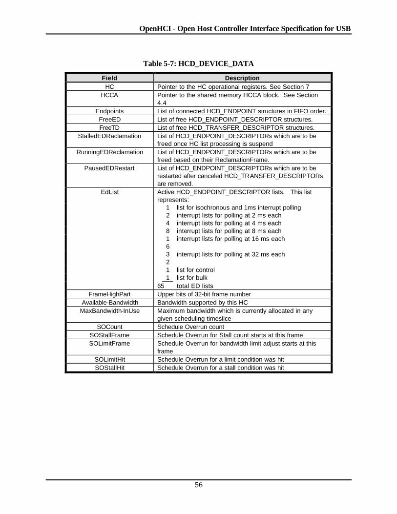
OpenHCI - Open Host Controller Interface Specification for USB
56
Table 5-7: HCD_DEVICE_DATA
Field Description HC Pointer to the HC operational registers. See Section 7
HCCA Pointer to the shared memory HCCA block. See Section 4.4
Endpoints List of connected HCD_ENDPOINT structures in FIFO order. FreeED List of free HCD_ENDPOINT_DESCRIPTOR structures. FreeTD List of free HCD_TRANSFER_DESCRIPTOR structures.
StalledEDRaclamation List of HCD_ENDPOINT_DESCRIPTORs which are to be freed once HC list processing is suspend
RunningEDReclamation List of HCD_ENDPOINT_DESCRIPTORs which are to be freed based on their ReclamationFrame.
PausedEDRestart List of HCD_ENDPOINT_DESCRIPTORs which are to be restarted after canceled HCD_TRANSFER_DESCRIPTORs are removed.
EdList Active HCD_ENDPOINT_DESCRIPTOR lists. This list represents:
1 list for isochronous and 1ms interrupt polling 2 interrupt lists for polling at 2 ms each 4 interrupt lists for polling at 4 ms each 8 interrupt lists for polling at 8 ms each 1
6 interrupt lists for polling at 16 ms each
32
interrupt lists for polling at 32 ms each
1 list for control 1 list for bulk 65 total ED lists
FrameHighPart Upper bits of 32-bit frame number Available-Bandwidth Bandwidth supported by this HC
MaxBandwidth-InUse Maximum bandwidth which is currently allocated in any given scheduling timeslice
SOCount Schedule Overrun count SOStallFrame Schedule Overrun for Stall count starts at this frame SOLimitFrame Schedule Overrun for bandwidth limit adjust starts at this
frame SOLimitHit Schedule Overrun for a limit condition was hit SOStallHit Schedule Overrun for a stall condition was hit

OpenHCI - Open Host Controller Interface Specification for USB
57
5.2.7 Endpoint Descriptor Lists The following sections describe Host Controller Driver handling of Endpoint Descriptors. In all cases, Host Controller Driver is responsible for the insertion and removal of all Endpoint Descriptors in the various Host Controller Endpoint Descriptor lists. Each subsection will outline how this is done for the various Host Controller endpoint lists. The EdList array in the Host Controller Driver device data structure is initialized at Host Controller Driver initialization such that all Head fields are properly initialized to be NULL lists and each PhysicalHead field contains the address to where the physical head pointer of the each list is maintained. This would be the address of either a HCD_ENDPOINT_DESCRIPTOR.HcED.NextED field, HccaInterruptTable[n], the HcControlHeadED register, or the HcBulkHeadED register.
5.2.7.1 Bulk and Control
The Host Controller has a list head for both bulk and control transfers. Each Endpoint Descriptor list is a separate list, but its maintenance semantics are the same for Host Controller Driver. The ED_CONTROL and ED_BULK entries of the EdList array are assumed to be initialized at Host Controller Driver initialization time such that the list Head field is initialized to a null list and the PhysicalHead field contains the address of the proper list head operational register.
5.2.7.1.1 Adding
When an Endpoint Descriptor is scheduled to either control or bulk, it is done by inserting a HCD_ENDPOINT_DESCRIPTOR into the proper HCD_ED_LIST.Head and then linking the HCD_ENDPOINT_DESCRIPTOR.HcEd into HCD_ED_LIST.PhysicalHead. VOID InsertEDForEndpoint ( IN PHCD_ENDPOINT Endpoint ) { PHCD_DEVICE_DATA DeviceData; PHCD_ED_LIST List; PHCD_ENDPOINT_DESCRIPTOR ED, TailED; DeviceData = Endpoint->DeviceData; List = &DeviceData->EdList[Endpoint->ListIndex];
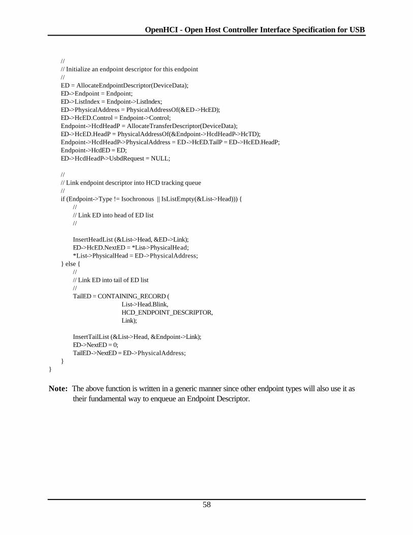
OpenHCI - Open Host Controller Interface Specification for USB
58
// // Initialize an endpoint descriptor for this endpoint // ED = AllocateEndpointDescriptor(DeviceData); ED->Endpoint = Endpoint; ED->ListIndex = Endpoint->ListIndex; ED->PhysicalAddress = PhysicalAddressOf(&ED->HcED); ED->HcED.Control = Endpoint->Control; Endpoint->HcdHeadP = AllocateTransferDescriptor(DeviceData); ED->HcED.HeadP = PhysicalAddressOf(&Endpoint->HcdHeadP->HcTD); Endpoint->HcdHeadP->PhysicalAddress = ED->HcED.TailP = ED->HcED.HeadP; Endpoint->HcdED = ED; ED->HcdHeadP->UsbdRequest = NULL; // // Link endpoint descriptor into HCD tracking queue // if (Endpoint->Type != Isochronous || IsListEmpty(&List->Head))) { // // Link ED into head of ED list // InsertHeadList (&List->Head, &ED->Link); ED->HcED.NextED = *List->PhysicalHead; *List->PhysicalHead = ED->PhysicalAddress; } else { // // Link ED into tail of ED list // TailED = CONTAINING_RECORD ( List->Head.Blink, HCD_ENDPOINT_DESCRIPTOR, Link); InsertTailList (&List->Head, &Endpoint->Link); ED->NextED = 0; TailED->NextED = ED->PhysicalAddress; } } Note: The above function is written in a generic manner since other endpoint types will also use it as
their fundamental way to enqueue an Endpoint Descriptor.

OpenHCI - Open Host Controller Interface Specification for USB
59
5.2.7.1.2 Removing
An Endpoint Descriptor is removed from a control or bulk list when the pipe on the endpoint is closed. Removing an Endpoint Descriptor involves correctly modifying the physical pointers being processed by the Host Controller to point around the Endpoint Descriptor being removed. This is accomplished by utilizing the virtual doubly-linked list which Host Controller Driver maintains for Endpoint Descriptors in its HCD_ENDPOINT_DESCRIPTOR structure.
ED ED ED
Figure 5-3: Removing an Endpoint Descriptor
As soon as the Endpoint Descriptor is removed from the physical list, it is freed from its corresponding endpoint structure. However, the actual memory for the Endpoint Descriptor cannot be reclaimed until it is known that the Host Controller is no longer referencing the Endpoint Descriptor. After the Endpoint Descriptor is removed from the list, it must be flushed from the Host Controller. The manner in which this is accomplished varies depending the type of list being modified. For control and bulk, the flush is done by clearing the appropriate bit in HcControl to halt the Host Controller from processing either the control or bulk list on the next frame. Once the next frame has started, the HcControlCurrentED or HcBulkCurrentED register should be adjusted so that it does not point to the Endpoint Descriptor being removed (for simplicity you may just write a zero to the register); the Endpoint Descriptor is now free and Host Controller Driver immediately sets the appropriate bit in HcControl to continue the list processing. VOID RemoveED ( IN PHCD_ENDPOINT Endpoint, IN BOOLEAN FreeED ) { PHCD_DEVICE_DATA DeviceData; PHCD_ED_LIST List; PHCD_ENDPOINT_DESCRIPTOR ED, PeviousED; ULONG ListDisable; DeviceData = Endpoint->DeviceData; List = &DeviceData->EdList[Endpoint->ListIndex]; ED = Endpoint->HcdED;

OpenHCI - Open Host Controller Interface Specification for USB
60
// // Prevent Host Controller from processing this ED // ED->HcED.Control.sKip = TRUE; // // Unlink the ED from the physical ED list // if (ED->Link.Blink == &List->Head) { // // Remove ED from head // *List->PhysicalHead = ED->HcED.NextED; PreviousED = NULL; } else { // // Remove ED from list // PreviousED = CONTAINING_RECORD ( ED->Link.Blink, HCD_ENDPOINT, Link); PreviousED->HcED.NextED = ED->HcED.NextED; } // // Unlink ED from HCD list // RemoveEntryList (&ED->Link); // // If freeing the endpoint, remove the descriptor // if (FreeED) { // TD queue must already be empty Endpoint->HcdED = NULL; ED->Endpoint = NULL; }

OpenHCI - Open Host Controller Interface Specification for USB
61
// // Check to see if interrupt processing is required to free the ED // switch (Endpoint->Type) { case Control: ListDisable = ~ControlListEnable; break; case Bulk: ListDisable = ~BulkListEnable; break; default: DeviceData->EDList[Endpoint->ListIndex].Bandwidth -= Endpoint->Bandwidth; DeviceData->MaxBandwidthInUse = CheckBandwidth( DeviceData, ED_INTERRUPT_32ms, &ListDisable); ListDisable = 0; } ED->ListIndex = ED_EOF; // ED is not on a list now // // Set ED for reclamation // DeviceData->HC->HcInterruptStatus = HC_INT_SOF; // clear SOF interrupt pending if (ListDisable) { DeviceData->HC->HcControl &= ListDisable; ED->ReclaimationFrame = Get32BitFrameNumber(DeviceData) + 1; InsertTailList (&DeviceData->StalledEDReclamation, &ED->Link); DeviceData->HC-> HcInterruptEnable = HC_INT_SOF; // interrupt on next SOF } else { ED->ReclaimationFrame = Get32BitFrameNumber(DeviceData) + 1; InsertTailList (&DeviceData->RunningEDReclamation, &ED->Link); } } By disabling the list processing in the HcControl register, the Host Controller disables processing of the list by the next EOF. Unmasking the SOF interrupt generates an interrupt status which signifies list processing has now been disabled. During the response to this interrupt event, the Host Controller Driver reclaims the Endpoint Descriptor. See Section 5.3 for more information on Host Controller Driver interrupt processing.

OpenHCI - Open Host Controller Interface Specification for USB
62
5.2.7.1.3 Pause
When a Transfer Descriptor is retired with an error or when the upper layers of software desire to cancel a transfer request, all Transfer Descriptors associated with the same request must be removed from the queue of transfers on the endpoint. To do this, processing of the endpoint by the Host Controller must be paused before the Host Controller Driver can remove or otherwise alter the Transfer Descriptors on the endpoint’s queue. There are two ways that this is accomplished, depending on the reason for pausing the endpoint: ?? When the Host Controller retires a Transfer Descriptor with an error, it automatically pauses
processing for that endpoint by setting the Halt bit in HC_ENDPOINT_DESCRIPTOR.HeadP. ?? When the upper layers of software initiate a cancel of a request, Host Controller Driver must set the
HC_ENDPOINT_DESCRIPTOR.Control.sKip bit and then ensure that the Host Controller is not processing that endpoint. After setting the bit, Host Controller Driver must wait for the next frame before the endpoint is paused.
VOID PauseED( IN PCHD_ENDPOINT Endpoint ) { PHCD_DEVICE_DATA DeviceData; PHCD_ENDPOINT_DESCRIPTOR ED; DeviceData = Endpoint->DeviceData; ED = Endpoint->HcdED; ED->HcED.Control.sKip = TRUE; if (ED->PausedFlag) return; // already awaiting pause processing if ( !(ED->HcED.HeadP & HcEDHeadP_HALT) ) { // // Endpoint is active in Host Controller, wait for SOF before processing the endpoint. // ED->PausedFlag = TRUE; DeviceData->HC->HcInterruptStatus = HC_INT_SOF; // clear SOF interrupt pending ED->ReclaimationFrame = Get32BitFrameNumber(DeviceData) + 1; InsertTailList (&DeviceData->PausedEDRestart, &ED->PausedLink); DeviceData->HC-> HcInterruptEnable = HC_INT_SOF; // interrupt on next SOF return; }

OpenHCI - Open Host Controller Interface Specification for USB
63
// // Endpoint already paused, do processing now // ProcessPausedED(ED); } VOID ProcessPausedED ( PHCD_ENDPOINT_DESCRIPTOR ED ) { PHCD_ENDPOINT endpoint; PUSBD_REQUEST request; PHCD_TRANSFER_DESCRIPTOR td, last = NULL, *previous; BOOLEAN B4Head = TRUE; endpoint = ED->Endpoint; if (endpoint == NULL) return; td = endpoint->HcdHeadP; previous = &endpoint->HcdHeadP; while (td != endpoint->HcdTailP) { if ((ED->HcED.HeadP & ~0xF) == td->PhysicalAddress) B4Head = FALSE; if (ED->ListIndex == ED_EOF || td->CancelPending) { // cancel TD request = td->UsbdRequest; RemoveListEntry(&td->RequestList); if (IsListEmpty(&request->HcdList) { request->Status = USBD_CANCELED; CompleteUsbdRequest(request); } *previous = td->NextHcdTD; // point around TD if (last != NULL) last->HcED.NextTD = td->HcED.NextTD; if (B4Head) // TD on delayed Done List td->Status = TD_CANCELED; else FreeTransferDescriptor(td); } else { // don’t cancel TD previous = &td->NextHcdTD; if (!B4Head) last = td; } td = *previous; } ED->HcED.HeadP = endpoint->HcdHeadP->PhysicalAddress | (ED->HcED.HeadP & HcEDHeadP_CARRY); ED->HcED.Control.sKip = FALSE; }
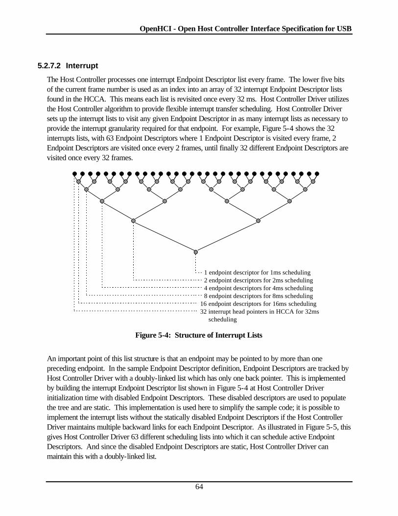
OpenHCI - Open Host Controller Interface Specification for USB
64
5.2.7.2 Interrupt
The Host Controller processes one interrupt Endpoint Descriptor list every frame. The lower five bits of the current frame number is used as an index into an array of 32 interrupt Endpoint Descriptor lists found in the HCCA. This means each list is revisited once every 32 ms. Host Controller Driver utilizes the Host Controller algorithm to provide flexible interrupt transfer scheduling. Host Controller Driver sets up the interrupt lists to visit any given Endpoint Descriptor in as many interrupt lists as necessary to provide the interrupt granularity required for that endpoint. For example, Figure 5-4 shows the 32 interrupts lists, with 63 Endpoint Descriptors where 1 Endpoint Descriptor is visited every frame, 2 Endpoint Descriptors are visited once every 2 frames, until finally 32 different Endpoint Descriptors are visited once every 32 frames.
1 endpoint descriptor for 1ms scheduling2 endpoint descriptors for 2ms scheduling4 endpoint descriptors for 4ms scheduling8 endpoint descriptors for 8ms scheduling
16 endpoint descriptors for 16ms scheduling32 interrupt head pointers in HCCA for 32ms scheduling
Figure 5-4: Structure of Interrupt Lists
An important point of this list structure is that an endpoint may be pointed to by more than one preceding endpoint. In the sample Endpoint Descriptor definition, Endpoint Descriptors are tracked by Host Controller Driver with a doubly-linked list which has only one back pointer. This is implemented by building the interrupt Endpoint Descriptor list shown in Figure 5-4 at Host Controller Driver initialization time with disabled Endpoint Descriptors. These disabled descriptors are used to populate the tree and are static. This implementation is used here to simplify the sample code; it is possible to implement the interrupt lists without the statically disabled Endpoint Descriptors if the Host Controller Driver maintains multiple backward links for each Endpoint Descriptor. As illustrated in Figure 5-5, this gives Host Controller Driver 63 different scheduling lists into which it can schedule active Endpoint Descriptors. And since the disabled Endpoint Descriptors are static, Host Controller Driver can maintain this with a doubly-linked list.
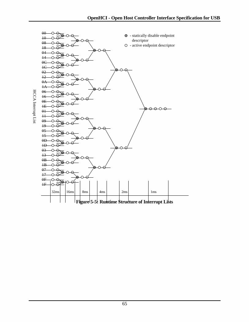
OpenHCI - Open Host Controller Interface Specification for USB
65
32ms 16ms 8ms 4ms 2ms 1ms
- statically disable endpoint descriptor- active endpoint descriptor
0010081804140C1C02120A1A06160E1E0111091905150D1D03130B1B07170F1F
HC
CA
Interrupt List
Figure 5-5: Runtime Structure of Interrupt Lists

OpenHCI - Open Host Controller Interface Specification for USB
66
The head of each scheduling list is either the static entry for that list or one of the 32 list heads in the HCCA area. This initialization is accomplished as follows: VOID InitailizeInterruptLists ( IN PHCD_DEVICE_DATA DeviceData ) { PHC_ENDPOINT_DESCRIPTOR ED, StaticED[ED_INTERRUPT_32ms]; ULONG i, j, k; static UCHAR Balance[16] = {0x0, 0x8, 0x4, 0xC, 0x2, 0xA, 0x6, 0xE, 0x1, 0x9, 0x5, 0xD, 0x3, 0xB, 0x7, 0xF}; // // Allocate satirically disabled EDs, and set head pointers for scheduling lists // for (i=0; i < ED_INTERRUPT_32ms; i+) { ED = AllocateEndpointDescriptor (DeviceData); ED->PhysicalAddress = PhysicalAddressOf(&ED->HcED); DeviceData->EDList[i].PhysicalHead = &ED->HcED.NextED; ED->HcED.Control |= sKip; // mark ED as disabled InitializeListHead (&DeviceData->EDList[i].Head); StaticED[i] = ED; if (i > 0) { DeviceData->EDList[i].Next = (i-1)/2; ED->HcED.NextED = StaticED[(i-1)/2]->PhysicalAddress; } else { DeviceData->EDList[i].Next = ED_EOF; ED->HcEd.NextED = 0; } } // // Set head pointers for 32ms scheduling lists which start from HCCA // for (i=0, j=ED_INTERRUPT_32ms, i<32; i++, j++) { DeviceData->EDList[j].PhysicalHead = &DeviceData->HCCA->InterruptList[i]; InitializeListHead (&DeviceData->EDList[j].Head); k = Balance[i & 0xF] + ED_INTERRUPT_16ms; DeviceData->EDList[j].Next = k; DeviceData->HCCA->InterruptList[i] = StaticED[k]->PhysicalAddress; } }

OpenHCI - Open Host Controller Interface Specification for USB
67
5.2.7.2.1 Polling Rate
Interrupt Endpoint Descriptors have a minimum rate for which they need to be scheduled. When this information is provided to Host Controller Driver, it determines the closest power of 2 rate below the endpoints requirement and determines which scheduling queue for that rate has the smallest committed bandwidth. The endpoint is then assigned to that scheduling list. USB_STATUS OpenPipe ( IN PHCD_ENDPOINT Endpoint ) { ULONG WhichList, junk; PHCD_DEVICE_DATA DeviceData; DeviceData = Endpoint->DeviceData; // // Determine the scheduling period. // WhichList = ED_INTERRUPT_32ms; while ( WhichList >= Endpoint->Rate && (WhichList >>= 1) ) continue; // // Commit this endpoints bandwidth to the proper scheduling slot // if (WhichList == ED_ISOCHRONOUS) { DeviceData->EDList[ED_ISOCHRONOUS ].Bandwidth += Endpoint->Bandwidth; DeviceData->MaxBandwidthInUse += Endpoint->Bandwidth; } else { // // Determine which scheduling list has the least bandwidth // CheckBandwidth(DeviceData, WhichList, &WhichList); DeviceData->EDList[WhichList].Bandwidth += Endpoint->Bandwidth; // // Recalculate the max bandwidth which is in use. This allows 1ms (isoc) pipe opens to // occur with few calculation // DeviceData->MaxBandwidthInUse = CheckBandwidth(DeviceData, ED_INTERRUPT_32ms, &junk); }

OpenHCI - Open Host Controller Interface Specification for USB
68
// // Verify the new max has not overcomitted the USB // if (DeviceData->MaxBandwidthInUse > DeviceData->AvailableBandwidth) { // // Too much, back this bandwidth out and fail the request // DeviceData->EDList[WhichList].Bandwidth -= Endpoint->Bandwidth; DeviceData->MaxBandwidthInUse = CheckBandwidth(DeviceData, ED_INTERRUPT_32ms, &junk); return CAN_NOT_COMMIT_BANDWIDTH; } // // Assign endpoint to list and open pipe // Endpoint->ListIndex = WhichList; // // Add to Host Controller schedule processing // InsertEDForEndpoint (Endpoint); } ULONG CheckBandwidth ( IN PHCD_DEVICE_DATA DeviceData, IN ULONG List, IN PULONG BestList ) /*++
This routine scans all the scheduling lists of frequency determined by the base List passed in and returns the worst bandwidth found (i.e., max in use by any given scheduling list) and the list which had the least bandwidth in use. List - must be a base scheduling list. I.e., it must be one of ED_INTERRUPT_1ms, ED_INTERRUPT_2ms, ED_INTERRUPT_4ms, ..., ED_INTERRUPT_32ms. All lists of the appropriate frequency are checked
--*/ { ULONG LastList, Index; ULONG BestBandwidth, WorstBandwidth; WorstBandwidth = 0; BestBandwidth = ~0;

OpenHCI - Open Host Controller Interface Specification for USB
69
for (LastList = List + List; List <= LastList; List ++) { // // Sum bandwidth in use in this scheduling time // Bandwidth = 0; for (Index=List; Index != ED_EOF; Index = DeviceData->EDList[Index].Next) { Bandwidth += DeviceData->EDList[index].Bandwidth; } // // Remember best and worst // if (Bandwidth < BestBandwidth) { BestBandwidth = Bandwidth; *BestList = List; } if (Bandwidth > WorstBandwidth) { WorstBandwidth = Bandwidth; } } return WorstBandwidth; }
5.2.7.2.2 Adding
Like control, bulk, and isochronous, interrupt Endpoint Descriptors are added to the Host Controller list for processing when the pipe on the endpoint is opened. This needs to be done after the polling policy and bandwidth for the interrupt endpoint has been set. See the same sample code in Section 5.2.7.1.1.
5.2.7.2.3 Removing
Since the Host Controller is obligated to process the periodic endpoint list for any given timeslice, removal of an interrupt Endpoint Descriptor from the schedule can be accomplished without interrupting the HC. The Endpoint Descriptor is removed from its corresponding endpoint list much the same way a bulk or control Endpoint Descriptor is removed, except that the processing of the endpoint list is not stalled. Instead, the Endpoint Descriptor is put off the RunningEDReclamation list and is reclaimed at some frame number in the future. For “freeing” of an endpoint, its Endpoint Descriptor is not reclaimed at a specific time, just whenever the next Host Controller interrupt processing occurs. For other operations which required an interrupt Endpoint Descriptor to be removed, like canceling of a transfer descriptor, an interrupt is forced at next SOF to ensure timely cleanup.

OpenHCI - Open Host Controller Interface Specification for USB
70
VOID UnscheduleIsochronousOrInterruptEndpoint ( IN PHCD_ENDPOINT Endpoint, IN BOOLEAN FreeED, IN BOOLEAN EndpointProcessingRequired ) { PHCD_DEVICE_DATA DeviceData; DeviceData = Endpoint->DeviceData; RemoveED(Endpoint, FreeED); // see sample code in Section 5.2.7.1.2. if (EndpointProcessingRequired) { DeviceData->HC-> HcInterruptEnable = HC_INT_SOF; // interrupt on next SOF } } During response to an interrupt event, Host Controller Driver would reclaim the available running Endpoint Descriptor list. See Section 5.3 for more information on Host Controller Driver interrupt processing.
5.2.7.2.4 Pause
Like control, bulk, and isochronous, when an interrupt Transfer Descriptor is retired with an error or when the upper layers of software desire to cancel a transfer request, all Transfer Descriptors associated with the same request must be removed from the queue of transfers on the endpoint. To do this, processing of the endpoint by the Host Controller must be paused before the Host Controller Driver can remove or otherwise alter the Transfer Descriptors on the endpoint’s queue. See Section 5.2.7.1.3 for a complete description.
5.2.7.3 Isochronous
Endpoint Descriptor management treats Isochronous Endpoint Descriptors just like 1-ms interrupt endpoints descriptors, except that they are added to the tail of the 1-ms interrupt list. This keeps the 1-ms scheduling list sorted such that 1-ms interrupt polling Endpoint Descriptors are listed before scheduled Isochronous Endpoint Descriptors. An isochronous endpoint could be setup by: Status = SetEndpointPolicies ( Endpoint, Isochronous, // Type 1, // Rate is 1ms Bandwidth // BandwidthRequired );
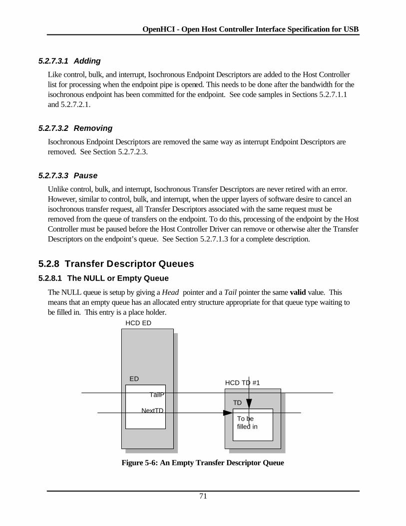
OpenHCI - Open Host Controller Interface Specification for USB
71
5.2.7.3.1 Adding
Like control, bulk, and interrupt, Isochronous Endpoint Descriptors are added to the Host Controller list for processing when the endpoint pipe is opened. This needs to be done after the bandwidth for the isochronous endpoint has been committed for the endpoint. See code samples in Sections 5.2.7.1.1 and 5.2.7.2.1.
5.2.7.3.2 Removing
Isochronous Endpoint Descriptors are removed the same way as interrupt Endpoint Descriptors are removed. See Section 5.2.7.2.3.
5.2.7.3.3 Pause
Unlike control, bulk, and interrupt, Isochronous Transfer Descriptors are never retired with an error. However, similar to control, bulk, and interrupt, when the upper layers of software desire to cancel an isochronous transfer request, all Transfer Descriptors associated with the same request must be removed from the queue of transfers on the endpoint. To do this, processing of the endpoint by the Host Controller must be paused before the Host Controller Driver can remove or otherwise alter the Transfer Descriptors on the endpoint’s queue. See Section 5.2.7.1.3 for a complete description.
5.2.8 Transfer Descriptor Queues 5.2.8.1 The NULL or Empty Queue
The NULL queue is setup by giving a Head pointer and a Tail pointer the same valid value. This means that an empty queue has an allocated entry structure appropriate for that queue type waiting to be filled in. This entry is a place holder.
ED
TailP
NextTDTD
HCD ED
HCD TD #1
To befilled in
Figure 5-6: An Empty Transfer Descriptor Queue

OpenHCI - Open Host Controller Interface Specification for USB
72
5.2.8.2 Adding to a Queue
Additions into transfer queues are always done by copying the new entry information to the entry at the tail of the queue and then appending a new tail entry to the queue. This is accomplished by:
1. Copying the new information to the entry pointed to by TailP 2. Setting the NextTD pointer in the current tail entry to a new place holder 3. Advancing the TailP pointer to the new place holder 4. Writing to the ControlListFilled or BulkListFilled bit in HcCommandStatus if the insert
was to a queue on the Control list or Bulk list.
ED
TailP
NextTD
TD
HCD ED
HCD TD #1
Nowfilled in
HCD TD #2
To befilled in
TD
12
3
Figure 5-7: Adding a Transfer Descriptor to a Queue
A limitation of this implementation is that there is always an unused entry at the tail of a queue. For queued requests, the Host Controller Driver needs to translate the USBD-passed entries into the native OpenHCI Transfer Descriptor entries which contain a back pointer to their corresponding USBD request.

OpenHCI - Open Host Controller Interface Specification for USB
73
The following code sample shows how the Host Controller Driver may convert USBD requests into General Transfer Descriptors (the process for Isochronous Transfer Descriptors is similar, but left as an exercise to the reader). BOOLEAN QueueGeneralRequest ( IN PHCD_ENDPOINT endpoint; IN USBD_REQUEST request; ) { PHCD_DEVICE_DATA DeviceData; PHCD_ENDPOINT_DESCRIPTOR ED; PHCD_TRANSFER_DESCRIPTOR TD, LastTD = NULL; ULONG RemainingLength, count; PCHAR CurrentBufferPointer; DeviceData = endpoint->DeviceData; ED = endpoint->HcdED; if (ED == NULL || ED->ListIndex == ED_EOF) return(FALSE); // endpoint has been removed from schedule. FirstTD = TD = endpoint->HcdHeadP; request->Status = USBD_NOT_DONE; RemainingLength = request->BufferLength; request->BufferLength = 0; // report back bytes transferred so far CurrentBufferPointer = request->Buffer; InitializeListHead(&request->HcdList); if (endpoint->Type == Control) { // // Setup a TD for setup packet // InsertTailList(&request->HcdList, &TD->RequestList); TD->UsbdRequest = request; TD->Endpoint = endpoint; TD->CancelPending = FALSE; TD->HcTD.CBP = PhysicalAddressOf(&request->setup[0]); TD->HcTD.BE = PhysicalAddressOf(&request->setup[7]); TD->TransferCount = 0; TD->HcTD.Control.DP = request->SETUP; TD->HcTD.Control.Toggle = 2; TD->HcTD.Control.R = TRUE; TD->HcTD.Control.IntD = 7; // specify no interrupt TD->HcTD.Control.CC = NotAccessed; TD->NextHcdTD = AllocateTransferDescriptor(DeviceData); TD->NextHcdTD->PhysicalAddress = TD->HcTd.NextTD = PhysicalAddressOf(&TD->NextHcdTD->HcTD); LastTD = TD; TD = TD->NextHcdTD; }
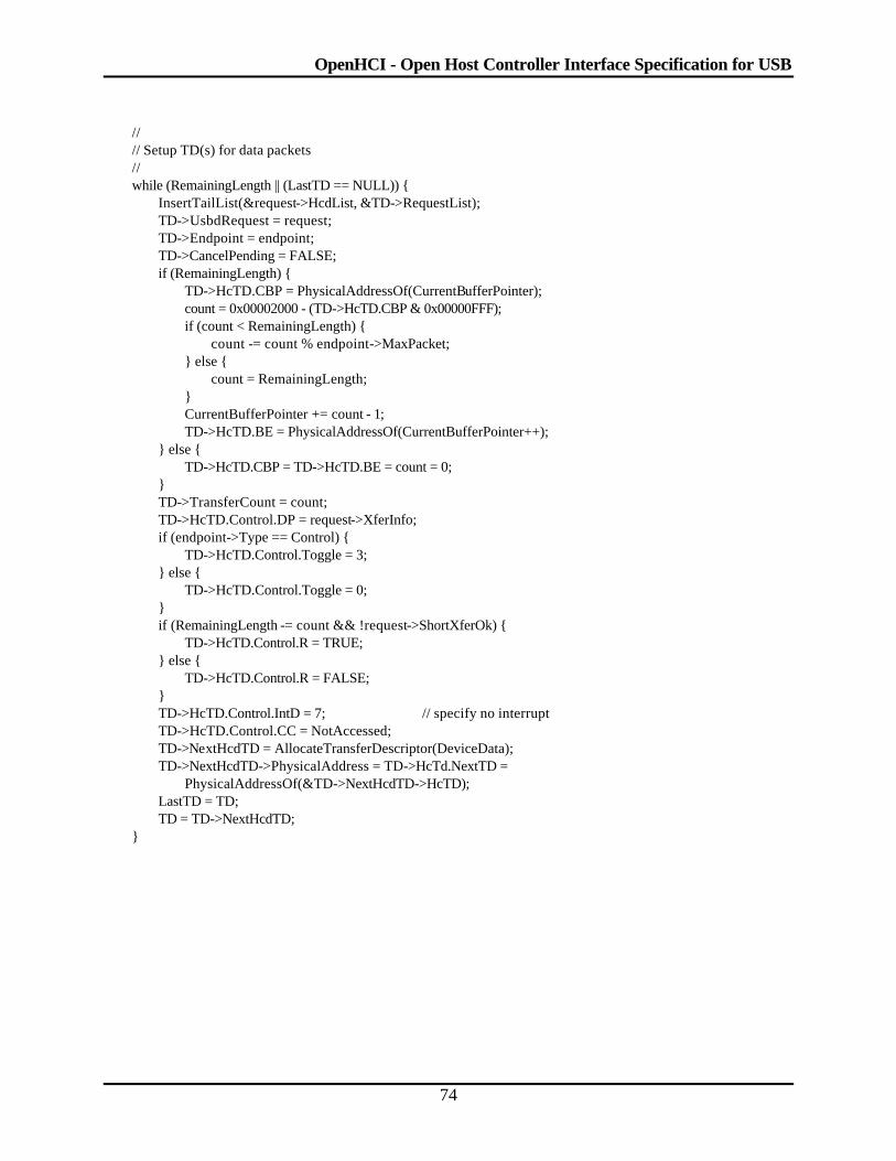
OpenHCI - Open Host Controller Interface Specification for USB
74
// // Setup TD(s) for data packets // while (RemainingLength || (LastTD == NULL)) { InsertTailList(&request->HcdList, &TD->RequestList); TD->UsbdRequest = request; TD->Endpoint = endpoint; TD->CancelPending = FALSE; if (RemainingLength) { TD->HcTD.CBP = PhysicalAddressOf(CurrentBufferPointer); count = 0x00002000 - (TD->HcTD.CBP & 0x00000FFF); if (count < RemainingLength) { count -= count % endpoint->MaxPacket; } else { count = RemainingLength; } CurrentBufferPointer += count - 1; TD->HcTD.BE = PhysicalAddressOf(CurrentBufferPointer++); } else { TD->HcTD.CBP = TD->HcTD.BE = count = 0; } TD->TransferCount = count; TD->HcTD.Control.DP = request->XferInfo; if (endpoint->Type == Control) { TD->HcTD.Control.Toggle = 3; } else { TD->HcTD.Control.Toggle = 0; } if (RemainingLength -= count && !request->ShortXferOk) { TD->HcTD.Control.R = TRUE; } else { TD->HcTD.Control.R = FALSE; } TD->HcTD.Control.IntD = 7; // specify no interrupt TD->HcTD.Control.CC = NotAccessed; TD->NextHcdTD = AllocateTransferDescriptor(DeviceData); TD->NextHcdTD->PhysicalAddress = TD->HcTd.NextTD = PhysicalAddressOf(&TD->NextHcdTD->HcTD); LastTD = TD; TD = TD->NextHcdTD; }

OpenHCI - Open Host Controller Interface Specification for USB
75
if (endpoint->Type == Control) { // // Setup TD for status phase // InsertTailList(&request->HcdList, &TD->RequestList); TD->Endpoint = endpoint; TD->UsbdRequest = request; TD->CancelPending = FALSE; TD->HcTD.CBP = 0; TD->HcTD.BE = 0; TD->TransferCount = 0; if (XferInfo == IN) { TD->HcTD.Control.DP = OUT; } else { TD->HcTD.ControlDP = IN: } TD->HcTD.Control.Toggle = 3; TD->HcTD.Control.R = FALSE; TD->HcTD.Control.IntD = 7; // specify no interrupt TD->HcTD.Control.CC = NotAccessed; TD->NextHcdTD = AllocateTransferDescriptor(DeviceData); TD->NextHcdTD->PhysicalAddress = TD->HcTd.NextTD = PhysicalAddressOf(&TD->NextHcdTD->HcTD); LastTD = TD; TD = TD->NextHcdTD; } // // Setup interrupt delay // LastTD->HcTD.Control.IntD = min(6, request->MaxIntDelay); // // Set new TailP in ED // TD->UsbdRequest = NULL; endpoint->HcdTailP = TD; ED->HcED.TailP = TD->PhysicalAddress; switch (endpoint->Type) { case Control: DeviceData->HC->HcCommandStatus = ControlListFilled; break; case Bulk: DeviceData->HC->HcCommandStatus = BulkListFilled; } return(TRUE); }

OpenHCI - Open Host Controller Interface Specification for USB
76
5.2.8.3 Removing from a Queue
Entries are typically removed from queues by the Host Controller upon completion of the Transfer Descriptor. At this point, the Host Controller adds the Transfer Descriptor to the Done Queue. When the Host Controller completes the Transfer Descriptor, it performs these steps:
1. Updates the NextTD pointer in the Endpoint Descriptor with the value from the NextTD in the Transfer Descriptor just completed.
2. Copies the value in HcDoneHead to the NextTD pointer in the completed Transfer Descriptor.
3. Places a pointer to the completed Transfer Descriptor into HcDoneHead.
ED
TailP
NextTD
TD
HCD ED
HCD TD #1
Nowcomplete
HCD TD #2
To befilled in
TD
TD
HCD TD #n
Nowcomplete
NULLHcDoneHead
231
Figure 5-8: Host Controller Removes a Transfer Descriptor from a Queue
Note that in the normal case, the Host Controller Driver does not in any way alter a Transfer Descriptor between the time TailP is moved to point beyond it until the Host Controller returns the Transfer Descriptor for Done processing. If the driver needs to modify a Transfer Descriptor once it has been given to the HC, it must use the cancel procedure described in the next section.
OpenHCI - Open Host Controller Interface Specification for USB
77
5.2.8.4 Cancel
In order to cancel Transfer Descriptors that have been passed to the Host Controller for processing (i.e., Transfer Descriptors on a queue prior to TailP), the driver must first ensure that the queue is not being processed by the HC. If a Transfer Descriptor was completed with an error, then the Host Controller will have stopped processing the queue as indicated by the H bit in the Endpoint Descriptor; otherwise, the driver must stop the processing of the queue by setting the sKip bit in the Endpoint Descriptor and waiting for the next SOF. (It is necessary to wait for the next SOF after setting the sKip bit because it is possible that the Host Controller is currently in the process of servicing the endpoint.) Once the queue is stopped, then the driver may alter or remove any of the Transfer Descriptors in the queue as well as update the NextTD and TailP pointers in the Endpoint Descriptor. When the driver has finished updating the queue, it re-enables processing of the queue by clearing both the Halt and sKip bits in the Endpoint Descriptor. BOOLEAN CancelRequest ( IN PUSBD_REQUEST request, ) { PHCD_TRANSFER_DESCRIPTOR TD; PHCD_ENDPOINT endpoint // // If request status is ‘not done’ set status to ‘canceling’ // if (request->Status != UDBD_NOT_DONE) return FALSE; // cannot cancel a completed request request->Status = USBD_CANCELING; TD = CONTAINING_RECORD( request->HcdList.FLink, HCD_TRANSFER_DESCRIPTOR, RequestList); while (TRUE) { TD->CancelPending = TRUE; if (TD->RequestList.FLink == request->HcdList.BLink) break; TD = CONTAINING_RECORD( TD->RequestList.FLink, HCD_TRANSFER_DESCRIPTOR, RequestList); } endpoint = TD->Endpoint; PauseED(endpoint); // stop endpoint, schedule cleanup (see Section 5.2.7.1.3) return TRUE; }

OpenHCI - Open Host Controller Interface Specification for USB
78
5.2.9 Done Queue The Done Queue is built by the Host Controller as each Transfer Descriptor is completed. The Host Controller later passes the queue to the Host Controller Driver through the HCCA. The Host Controller Driver must reverse the order of the queue as it converts the physical addresses in the queue to virtual addresses that can be used by software. Once the queue is reversed, it can be processed in the order that the Transfer Descriptors were completed. This processing must account for Transfer Descriptors that have been completed normally as well as those that are completed with errors. Some of the Transfer Descriptors completed with Data Underrun errors are not considered as errors by the upper layers of the USB software and must be handled by Host Controller Driver. Additionally, the Host Controller Driver must allow for the possibility that the Transfer Descriptor only accounts for a portion of the original transfer request from the USB Driver. VOID ProcessDoneQueue ( ULONG physHcTD // HccaDoneHead ) { PHCD_TRANSFER_DESCRIPTOR TD, tn, TDlist = NULL; PUSBD_REQUEST Request; PHCD_ENDPOINT Endpoint; // // Reverse the queue passed from controller while virtualizing addresses. // NOTE: The following code assumes that a ULONG and a pointer are the same size // if (physHcTD == 0) return; do { TD = CONTAINING_RECORD( VirtualAddressOf(physHcTD), HCD_TRANSFER_DESCRIPTOR, HcTD ); physHcTD = TD->HcTD.NextTD; TD->HcTD.NextTD = (ULONG) TDlist; TDlist = TD; } while (physHcTD); // // Process list that is now reordered to completion order // while (TDlist != NULL) { TD = TDlist; TDlist = (PHCD_TRANSFER_DESCRIPTOR) (TD->HcTD.NextTD); if (TD->Status == TD_CANCELED) { FreeTransferDescriptor(TD); continue;

OpenHCI - Open Host Controller Interface Specification for USB
79
} Request = TD->UsbdRequest; Endpoint = TD->Endpoint; if (Endpoint->Type != Isochronous) { if (TD->HcTD.CBP) { TD->TransferCount -= (((TD->HcTD.BE ^ TD->HcTD.CBP) & 0xFFFFF000) ? 0x00001000 : 0) + (TD->HcTD.BE & 0x00000FFF) - (TD->HcTD.CBP & 0x00000FFF) + 1; } if (TD->HcTD.Control.DP != Setup ) { Request->BufferLength += TD->TransferCount; } if (TD->HcTD.Control.CC == NoError) { // // TD completed without error, remove it from USBD_REQUEST list, // if USBD_REQUEST list is now empty, then complete the request. // Endpoint->HcdHeadP = TD->NextHcdTD; RemoveListEntry(&TD->RequestList); FreeTransferDescriptor(TD); if (IsListEmpty(&Request->HcdList)) { if (Request->Status != USBD_CANCELING) Request->Status = USBD_NORMAL_COMPLETION; else Request->Status = USBD_CANCELED; CompleteUsbdRequest(Request); } } else { // // TD completed with an error, remove it and other TDs for same request, // set appropriate status in USBD_REQUEST and then complete it. There // are two special cases: 1) error is DataUnderun on Bulk or Interrupt and // ShortXferOk is true; for this do not report error to USBD and restart // endpoint. 2) error is DataUnderrun on Control and ShortXferOk is true; // for this the final status TD for the Request should not be canceled, the // Request should not be completed, and the endpoint should be restarted. // NOTE: The endpoint has been halted by the controller // for ( tn = Endpoint->HcdHeadP; tn != Endpoint->HcdTailP; tn = tn->NextHcdTD ) { if (Request != tn->UsbdRequest || ( TD->HcTD.Control.CC == DataUnderrun && Request->ShortXferOk && Request->Status != USBD_CANCELING && TD->HcTD.Control.DP != tn->HcTD.Control.DP)) break;

OpenHCI - Open Host Controller Interface Specification for USB
80
} Endpoint->HcdHeadP = tn; Endpoint->HcdED->HcED.HeadP = tn->PhysicalAddress | (Endpoint->HcED->HcED.HeadP & (HcEDHeadP_HALT | HcEDHeadP_CARRY)); while ((tn = CONTAINING_RECORD( RemoveListHead(&Request->HcdList), HCD_TRANSFER_DESCRIPTOR, RequestList )) != NULL) { if (tn != TD && tn != Endpoint->HcdHeadP) FreeTransferDescriptor(tn); } if (Endpoint->HcdHeadP->UsbdRequest == Request) { InsertTailList(&Request->HcdList, &Endpoint->HcdHeadP->RequestList); Endpoint->HcdED->HcED.HeadP &= ~HcEDHeadP_HALT; } else { if (Request->ShortXferOk && (TD->HcTD.Control.CC == DataUnderrun)) { if (Request->Status != USBD_CANCELING) Request->Status = USBD_NORMAL_COMPLETION; else Request->Status = USBD_CANCELED; Endpoint->HcdED->HcED.HeadP &= ~HcEDHeadP_HALT; } else if (Request->Status != USBD_CANCELING) { Request->Status = USBD_CC_Table[TD->HcTD.Control.CC]; } else { Request->Status = USBD_CANCELED; } CompleteUsbdRequest(Request); } FreeTransferDescriptor(TD); } } else { // // Code for Isochronous is left as an exercise to the reader // } } }

OpenHCI - Open Host Controller Interface Specification for USB
81
5.2.10 USB Bandwidth Allocation The Host Controller Driver initializes a value in its device data which reflects the total bandwidth available which can be committed on the USB for periodic events. This would be the maximum amount of any USB frame which can be consumed by interrupt and isochronous packets. When a pipe on an endpoint is opened for usage, its bandwidth is allocated. The bandwidth used by an interrupt or isochronous endpoint must therefore be set before the pipe is opened and any transfers are performed. All transfers performed on the pipe must not exceed the bandwidth which has been set. This is part of the USBDI interface and the Host Controller Driver does not need to verify this. The Host Controller Driver tracks all allocated bandwidth for every periodic scheduling list it can schedule into. When a pipe needs to allocate bandwidth, the Host Controller Driver first checks to make sure that such an allocation would not exceed the maximum allowed allocations by checking the schedule lists of the deepest depth (i.e., the 32-ms schedules). If no 32-ms schedule will overflow, the Host Controller Driver determines which of the scheduling lists (of those that are valid for the allocation request) has the least currently allocated bandwidth. The bandwidth is committed and the Endpoint Descriptor is assigned to that scheduling slot. Isochronous bandwidth allocations are the same as interrupt bandwidth allocation of a frequency of 1ms. See Section 5.2.7.2.1 on interrupt polling rate for related information.
5.2.10.1 Scheduling Overrun Errors
SchedulingOverrun errors occur when the Host Controller is not able to complete all the interrupt and isochronous transfers prior to the end of the frame. Since the Host Controller Driver does not allow the USB frames to be overcommitted, the cause of SchedulingOverrun errors is the inability of the Host Controller to gain timely access to the host bus. This is normally a transient condition that can be ignored because the transfers most likely to be missed are the isochronous transfers at the end of the periodic list; since isochronous is not a guaranteed delivery stream, the listener must be able to deal with missing data. However, it is possible that due to a particular system configuration, the condition may persist for long periods of time. If SchedulingOverrun errors occur in 100 consecutive frames, it is recommended that the Host Controller Driver reduce the committed bandwidth on the bus and make a note of the new available bandwidth, preferably in a place where the information can persist between OS boots.

OpenHCI - Open Host Controller Interface Specification for USB
82
Normally the Host Controller can recover from SchedulingOverrun errors (see Section 4.3.2.3.5.3, Time Errors). However, if SchedulingOverrun errors persist for 32759 consecutive frames, then stale Isochronous Transfer Descriptors in the periodic list can look like Isochronous Transfer Descriptors that are scheduled for later delivery (this may not appear serious, but transmitting an isochronous packet in any but its assigned frame can cause serious problems, not to mention that any packet status words that may have been written may be mistaken by the Host Controller as buffer offsets, causing even more problems). Therefore, it is necessary that the Host Controller Driver clear the IsochronousEnable bit in the HcControl register when it detects that this situation is about to occur. This said, it must be noted that it is nearly impossible for this situation to occur because the Host Controller Driver should have attempted to reduce the committed bandwidth 327 times, to no avail. Since it is possible that the same host bus situation that prevents the Host Controller from completing its schedule can cause the host processor to stall and thus miss a SchedulingOverrun interrupt, the Host Controller provides the ErrorFrameCount in the HcCommandStatus register to assist the Host Controller Driver in keeping track of the number of consecutive SchedulingOverrun errors.
5.2.11 ControlBulkServiceRatio The USB Specification requires that control transfers be given preference over bulk transfers. The OpenHCI Host Controller achieves this with the ControlBulkServiceRatio field in the HcControl register. Host Controller Driver merely sets this field to the number of control endpoints that should be serviced for each bulk endpoint that is serviced. For the purposes of the ControlBulkServiceRatio Endpoint Descriptors that have either the sKip or Halt bits set or have HeadP equal to TailP are not counted.
OpenHCI - Open Host Controller Interface Specification for USB
83
5.3 Host Controller Interrupt When the Host Controller needs attention it requests a processor interrupt. The following sample code for HCD’s interrupt service routine primarily shows the normal case for the USBOPERATIONAL state. BOOLEAN HcdInterruptService( IN HCD_DEVICE_DATA DeviceData ) { // define some variables ULONG ContextInfo, Temp, Temp2, Frame; // // Is this our interrupt? // if (DeviceData->HCCA->HccaDoneHead != 0) { ContextInfo = WritebackDoneHead; // note interrupt processing required if (DeviceData->HCCA->DoneHead & 1) { ContextInfo |= DeviceData->HC->HcInterruptStatus & DeviceData->HC->HcInterruptEnable; } } else { ContextInfo = DeviceData->HC->HcInterruptStatus & DeviceData->HC->HcInterruptEnable; if (ContextInfo == 0) return FALSE; // not my interrupt } // // It is our interrupt, prevent HC from doing it to us again until we are finished // DeviceData->HC->HcInterruptDisable = MasterInterruptEnable; if (ContextInfo & UnrecoverableError) { // // The controller is hung, maybe resetting it can get it going again. But that code is left as an exercise to // the reader. // }

OpenHCI - Open Host Controller Interface Specification for USB
84
if (ContextInfo & (SchedulingOverrun | WritebackDoneHead | StartOfFrame | FrameNumberOverflow)) ContextInfo |= MasterInterruptEnable; // flag for end of frame type interrupts // // Check for Schedule Overrun // if (ContextInfo & SchedulingOverrun) { Frame = Get32BitFrameNumber(DeviceData); Temp2 = DeviceData->HC->HcCommandStatus & EFC_Mask; Temp = Temp2 - (DeviceData->SOCount & EFC_Mask); Temp = (((Temp >> EFC_Position) - 1) % EFC_Size) + 1; // number of bad frames since last error if ( !(DeviceData->SOCount & SOC_Mask) || // start a new count? ((DeviceData->SOCount & SOC_Mask) + DeviceData->SOStallFrame + Temp) != Frame) { DeviceData->SOLimitFrame = DeviceData->SOStallFrame = Frame - Temp; DeviceData->SOCount = Temp | Temp2; } else { // got a running count DeviceData->SOCount = (DeviceData->SOCount + Temp) & SOC_Mask | Temp2; while (Frame - DeviceData->SOLimitFrame >= 100) { DeviceData->SOLimitHit++; DeviceData->SOLimitFrame += 100; } if (Frame - DeviceData->SOStallFrame >= 32740) { DeviceData->HC->HcControl &= ~IsochronousEnable; // stop isochronous transfers DeviceData->SOStallHit = TRUE; DeviceData->SOCount = Temp2; // clear error counter } } DeviceData->HC->HcInterruptStatus = SchedulingOverrun; // acknowledge interrupt ContextInfo &= ~SchedulingOverrun; } else { // no schedule overrun, check for good frame. if (ContextInfo & MasterInterruptEnable) DeviceData->SOCount &= EFC_MASK; // clear counter } // // Check for Frame Number Overflow // Note: the formula below prevents a debugger break from making the 32-bit frame number run backward. // if (Context Info & FrameNumberOverflow) { DeviceData->FrameHighPart += 0x10000 - ((DeviceData->HCCA->HccaFrameNumber ^ DeviceData->FrameHighPart) & 0x8000); DeviceData->HC->HcInterruptStatus = FrameNumberOverflow; // acknowledge interrupt ContextInfo &= ~FrameNumberOverflow; } // // Processor interrupts could be enabled here and the interrupt dismissed at the interrupt // controller, but for simplicity this code won’t. //

OpenHCI - Open Host Controller Interface Specification for USB
85
if (ContextInfo & ResumeDetected) { // // Resume has been requested by a device on USB. HCD must wait 20ms then put controller in the // UsbOperational state. This code is left as an exercise to the reader. // ContextInfo &= ~ResumeDetected; DeviceData->HC->HcInterruptStatus = ResumeDetected; } // // Process the Done Queue // if (ContextInfo & WritebackDoneHead) { ProcessDoneQueue(DeviceData ->HccaDoneHead); // // Done Queue processing complete, notify controller // DeviceData->HCCA->HccaDoneHead = 0; DeviceData->HC->HcInterruptStatus = WritebackDoneHead; ContextInfo &= ~WritebackDoneHead; } // // Process Root Hub changes // if (ContextInfo & RootHubStatusChange) { // // EmulateRootHubInterruptXfer will complete a HCD_TRANSFER_DESCRIPTOR which // we then pass to ProcessDoneQueue to emulate an HC completion // ProcessDoneQueue(EmulateRootHubInterruptXfer(DeviceData)->PhysicalAddress); // // leave RootHubStatusChange set in ContextInfo so that it will be masked off (it won’t be unmasked // again until another TD is queued for the emulated endpoint) // } if (ContextInfo & OwnershipChange) { // // Only SMM drivers need implement this. See Sections 5.1.1.3.3 and 5.1.1.3.6 for descriptions of what // the code here must do. // } // // Any interrupts left should just be masked out. (This is normal processing for StartOfFrame and // RootHubStatusChange) // if (ContextInfo & ~MasterInterruptEnable) // any unprocessed interrupts? DeviceData->HC->HcInterruptDisable = ContextInfo; // yes, mask them

OpenHCI - Open Host Controller Interface Specification for USB
86
// // We’ve completed the actual service of the HC interrupts, now we must deal with the effects // // // Check for Scheduling Overrun limit // if (DeviceData->SOLimitHit) { do { PHCD_ENDPOINT_DESCRIPTOR ED; if (IsListEmpty(EDList[ED_ISOCHRONOUS].Head)) break; // Isochronous List is empty ED = CONTAINING_RECORD( EDList[ED_ISOCHRONOUS].Head.Blink, HCD_ENDPOINT_DESCRIPTOR, Link); if (ED->Endpoint->Type != Isochronous) break; // Only 1ms Interrupts left on list DeviceData->AvailableBandwidth = DeviceData->MaxBandwidthInUse - 64; // // It is recommended that the above bandwidth be saved in non-volatile memory for future use. // RemoveED(ED->Endpoint); } while (--DeviceData->SOLimitHit); DeviceData->SOLimitHit = 0; } // // look for things on the PausedEDRestart list // Frame = Get32BitFrameNumber(DeviceData); while (!IsListEmpty(&DeviceData->PausedEDRestart) { PHCD_ENDPOINT_DESCRIPTOR ED; ED = CONTAINING_RECORD( DeviceData->PausedEDRestart.FLink, HCD_ENDPOINT_DESCRIPTOR, PausedLink); if ((LONG)(ED->ReclaimationFrame - Frame) > 0) break; RemoveListEntry(&ED->PausedLink); ED->PausedFlag = FALSE; ProcessPausedED(ED); }

OpenHCI - Open Host Controller Interface Specification for USB
87
// // look for things on the StalledEDReclamation list // if (ContextInfo & MasterInterruptEnable && !IsListEmpty(&DeviceData->StalledEDReclamation) { Temp = DeviceData->HC->HcControlCurrentED; Temp2 = DeviceData->HC->HcBulkCurrentED; while (!IsListEmpty(&DeviceData->StalledEDReclamation) { PHCD_ENDPOINT_DESCRIPTOR ED; ED = CONTAINING_RECORD( DeviceData->StalledEDReclamation.FLink, HCD_ENDPOINT_DESCRIPTOR, Link); RemoveListEntry(&ED->Link); if (ED->PhysicalAddress == Temp) DeviceData->HC->HcControlCurrentED = Temp = ED->HcED.NextED; else if (ED->PhysicalAddress == Temp2) DeviceData->HC->HcBulkCurrentED = Temp2 = ED->HcED.NextED; if (ED->Endpoint != NULL) { ProcessPausedED(ED); // cancel any outstanding TDs } else { FreeEndpointDescriptor(ED); } } DeviceData->HC->HcControl |= ControlListEnable | BulkListEnable; // restart queues } // // look for things on the RunningEDReclamation list // Frame = Get32BitFrameNumber(DeviceData); while (!IsListEmpty(&DeviceData->RunningEDReclamation) { PHCD_ENDPOINT_DESCRIPTOR ED; ED = CONTAINING_RECORD( DeviceData->RunningEDReclamation.FLink, HCD_ENDPOINT_DESCRIPTOR, Link); if ((LONG)(ED->ReclaimationFrame - Frame) > 0) break; RemoveListEntry(&ED->Link); if (ED->Endpoint != NULL) ProcessPausedED(ED); // cancel any outstanding TDs else FreeEndpointDescriptor(ED); } // // If processor interrupts were enabled earlier then they must be disabled here before we re-enable // the interrupts at the controller. // DeviceData->HC->HcInterruptEnable = MasterInterruptEnable; return TRUE; }
OpenHCI - Open Host Controller Interface Specification for USB
88
5.4 FrameInterval Counter The HcFmInterval register is used to control the length of USB frames. The proper value for this register, the one that generates SOF tokens at a rate within the limits specified by the USB Specification, is set by system firmware if it is different from the HcFmInterval register’s reset value; therefore, the Host Controller Driver should save this value when entered in order to be able to restore the proper value after resets. The FrameInterval field in the HcFmInterval register may be adjusted by plus or minus one count no more frequently than every six USB frames. This means it is necessary to know in which frame a new FrameInterval takes effect. This can be accomplished by using the T bit in the HcFmInterval and HcFmRemaining registers. When writing the HcFmInterval register, the Host Controller Driver simply writes the T bit as the inverse of the T bit in the HcFmRemaining register; when the next SOF occurs, both the T bit and the FrameInterval field will be copied to the HcFmRemaining register. When setting the HcFmInterval register, not only the FrameInterval field must be updated but also the FSLargestDataPacket field must be set. This field initializes a counter within the Host Controller that is used to determine if a transaction on USB can be completed before EOF processing must start. It is a function of the new FrameInterval and is calculated by subtracting from FrameInterval the maximum number of bit times for transaction overhead on USB and the number of bit times needed for EOF processing, then multiplying the result by 6/7 to account for the worst case bit stuffing overhead. The value of MAXIMUM_OVERHEAD below is 210 bit times. The sample code below has purposely not defined the value of HcFmInterval as a structure so that the entire register can be updated in a single write operation. This is necessary to ensure that all the fields within HcFmInterval are updated together for consistency. ULONG SetFrameInterval ( IN PHCD_DEVICE_DATA DeviceData, IN BOOLEAN UpNotDown ) { ULONG FrameNumber, Interval;

OpenHCI - Open Host Controller Interface Specification for USB
89
Interval |= (DeviceData->HC->HcFmInterval & 0x00003FFF); if (UpNotDown) ++Interval; else --Interval; Interval |= (((Interval - MAXIMUM_OVERHEAD) * 6) / 7) << 16; Interval |= 0x80000000 & (0x80000000 ^ (DeviceData->HC->HcFmRemaining)); FrameNumber = Get32BitFrameNumber(DeviceData); DeviceData->HC->HcFmInterval = Interval; if (0x80000000 & (DeviceData->HC->HcFmRemaining ^ Interval)) { FrameNumber += 1); } else { FrameNumber = Get32BitFrameNumber(DeviceData); } return (FrameNumber); // return frame number new interval takes effect } ULONG Get32BitFrameNumber( HCD_DEVICE_DATA DeviceData ) { ULONG fm, hp; // // This code accounts for the fact that HccaFrameNumber is updated by the HC before the HCD gets an // interrupt that will adjust FrameHighPart. // hp = DeviceData->FrameHighPart; fm = DeviceData->HCCA->HccaFrameNumber; return ((fm & 0x7FFF) | hp) + ((fm ^ hp) & 0x8000); }
5.5 Root Hub The Host Controller Driver is responsible for making all endpoints to the root hub appear as a normal hub endpoint to USBD. This involves virtualizing the endpoint communications and ,as necessary, maintaining the HcRtHubStatus register. After a transition out of the USBReset state, the Host Controller Driver must make the root hub appear at the default address. See the USB Specification for the details of the expected behavior of the root hub.

OpenHCI - Open Host Controller Interface Specification for USB
90
6. HOST CONTROLLER 6.1 Introduction
This chapter discusses the Host Controller. The Host Controller is the device which is located between the USB bus and the Host Controller Driver in the OpenHCI architecture. The Host Controller is charged with processing all of the Data Type lists built by the Host Controller Driver. Additionally, the USB Root Hub is attached to the Host Controller. This chapter is organized into the following sections:
? USB States This section discusses the Host Controller Operation with respect to the possible USB Bus states.
? Frame Management This section discusses all aspects of managing the 1-ms USB Frame. ? List Processing List Processing is the main function of the Host Controller. This
section describes the detailed processing of the HCD-built Data Type lists.
? Interrupt Processing This section describes the interrupt events tracked by the Host Controller and how the Host Controller provides interrupts for those events.
? Root Hub This section describes the Root Hub support.
6.2 USB States The Host Controller has four USB states visible to the Host Controller Driver via the Operational Registers: USBOPERATIONAL, USBRESET, USBSUSPEND, and USBRESUME. These states define the Host Controller responsibilities relating to USB signaling and bus states. The USB states are reflected in the HostControllerFunctionalState field of the HcControl register. The Host Controller Driver is permitted to perform only the USB state transitions shown in Figure 6-1. The Host Controller may only perform a single state transition. During a remote wakeup event, the Host Controller may transition from USBSUSPEND to USBRESUME.

OpenHCI - Open Host Controller Interface Specification for USB
91
USBOPERATIONAL
USBSUSPEND
USB RESETUSB RESUME
USBOPERATIONAL write
USBRESET write
Software Reset
USBSUSPEND writeUSBRESET write
USBRESUME writeor
Remote Wakeup
Hardware Reset
USBOPERATIONAL write
USBRESET write
Figure 6-1: USB States
6.2.1 UsbOperational When in the USBOPERATIONAL state, the Host Controller may process lists and will generate SOF Tokens. The USBOPERATIONAL state may be entered from the USBRESUME or USBRESET states. It may be exited to the USBRESET or USBSUSPEND states. When transitioning from USBRESET or USBRESUME to USBOPERATIONAL, the Host Controller is responsible for terminating the USB reset or resume signaling as defined in the USB Specification prior to sending a token. A transition to the USBOPERATIONAL state affects the frame management registers of the Host Controller. Simultaneously with the Host Controller’s state transition to USBOPERATIONAL, the FrameRemaining field of HcFmRemaining is loaded with the value of the FrameInterval field in HcFmInterval. There is no SOF Token sent at this initial load of the FrameRemaining field. The first SOF Token sent after entering the USBOPERATIONAL state is sent following next frame boundary when FrameRemaining transitions from 0 to FrameInterval. The FrameNumber field of HcFmNumber is incremented on a state transition to USBOPERATIONAL.

OpenHCI - Open Host Controller Interface Specification for USB
92
6.2.2 UsbReset When in the USBRESET state, the Host Controller forces reset signaling on the bus. The Host Controller’s list processing and SOF Token generation are disabled while in USBRESET. In addition, the FrameNumber field of HcFmNumber does not increment while the Host Controller is in the USBRESET state. The USBRESET state can be entered from any state at any time. The Host Controller defaults to the USBRESET state following a hardware reset. The Host Controller Driver is responsible for satisfying USB Reset signaling timing defined by the USB Specification.
6.2.3 UsbSuspend The USBSUSPEND state defines the USB Suspend state. The Host Controller’s list processing and SOF Token generation are disabled. However, the Host Controller’s remote wakeup logic must monitor USB wakeup activity. The FrameNumber field of HcFmNumber does not increment while the Host Controller is in the USBSUSPEND state. USBSUSPEND is entered following a software reset or from the USBOPERATIONAL state on command from the Host Controller Driver. While in USBSUSPEND, the Host Controller may force a transition to the USBRESUME state due to a remote wakeup condition. This transition may conflict with the Host Controller Driver initiating a transition to the USBRESET state. If this situation occurs, the HCD-initiated transition to USBRESET has priority. The Host Controller Driver must wait 5 ms after transitioning to USBSUSPEND before transitioning to the USBRESUME state. Likewise, the Root Hub must wait 5 ms after the Host Controller enters USBSUSPEND before generating a local wakeup event and forcing a transition to USBRESUME. Following a software reset, the Host Controller Driver may cause a transition to USBOPERATIONAL if the transition occurs no more than 1 ms from the transition into USBSUSPEND. If the 1-ms period is violated, it is possible that devices on the bus will go into Suspend.
6.2.4 UsbResume When in the USBRESUME state, the Host Controller forces resume signaling on the bus. While in USBRESUME, the Root Hub is responsible for propagating the USB Resume signal to downstream ports as specified in the USB Specification. The Host Controller's list processing and SOF Token generation are disabled while in USBRESUME. In addition, the FrameNumber field of HcFmNumber does not increment while the Host Controller is in the USBRESUME state. USBRESUME is only entered from USBSUSPEND. The transition to USBRESUME can be initiated by the Host Controller Driver or by a USB remote wakeup signaled by the Root Hub. The Host Controller is responsible for resolving state transition conflicts between the hardware wakeup and Host Controller Driver initiated state transitions. Legal state transitions from USBRESUME are to USBRESET and to USBOPERATIONAL. The Host Controller Driver is responsible for USB Resume signal timing as defined by the USB Specification.

OpenHCI - Open Host Controller Interface Specification for USB
93
6.3 Frame Management The Host Controller is responsible for managing all aspects of “framing” for the USB. These responsibilities include the sending of SOF Tokens on the bus and communicating with the Host Controller Driver on frame-specific information.
6.3.1 Frame Timing The Host Controller uses three registers to perform the frame timing and information reporting tasks of frame management. The 16-bit FrameNumber field of the HcFmNumber register is kept by the Host Controller as a reference number for the current frame. This frame number is sent over the USB as the Frame Number field in SOF Tokens and is reported by the Host Controller to the HCCA for use by the Host Controller Driver. The FrameInterval field of the HcFmInterval register and the FrameRemaining field of the HcFmRemaining register are used to define frame boundaries. The FrameInterval field stores the length of a USB frame in 12-MHz bit times. Specifically, the FrameInterval field corresponds to (Frame Length - 1) bit times. FrameInterval is loaded with a default value of 0x2EDF (11,999 decimal) at reset. This value produces a USB frame consisting of exactly 12,000 bit times. The Host Controller Driver may vary the value of FrameInterval at any time. The FrameRemaining field functions as a 14-bit frame counter. When operating, the register value decrements once per USB bit time. When FrameRemaining reaches a value of 0, it is loaded with the value of the FrameInterval field at the next bit-time boundary. The frame boundary is the bit boundary on which the value of FrameRemaining transitions from 0 to FrameInterval (a J to K transition is seen on the USB at this boundary signifying the first bit of the sync field of an SOF Token - see Section 6.3.2). In other words, the last bit time for a frame is defined as the bit time in which the value of FrameRemaining is 0. The first bit time for a frame is defined as the bit time in which the value of FrameRemaining is equal to FrameInterval. The HcFmNumber register holds the current frame number in the FrameNumber field. This field is incremented by the Host Controller at each frame boundary. FrameNumber is incremented when the FrameRemaining field transitions from 0 to FrameInterval. The FrameNumber field may be used by the Host Controller Driver in the construction of a larger resolution frame number. To aid the Host Controller Driver in this task, the Host Controller writes the FrameNumber field to HccaFrameNumber immediately following the change in value of FrameNumber at the beginning of the frame. Immediately following the completion of the write of FrameNumber to HccaFrameNumber, the Host Controller sets the StartOfFrame bit in the HcInterruptStatus register to signify a StartOfFrame interrupt event.

OpenHCI - Open Host Controller Interface Specification for USB
94
6.3.2 StartOfFrame (SOF) Token Generation When in the USBOPERATIONAL state the Host Controller generates an SOF Token at the beginning of each frame period. There are no SOF Tokens generated when the Host Controller is in a state other than USBOPERATIONAL. The Host Controller must be exact in its delivery of the SOF token to the USB. All OpenHCI Host Controllers send the first bit of the SOF Token SYNC field during the first bit time of the frame. The timing of the SOF Token on the bus is shown in Figure 6-2.
0x0001 0x0000 0x2EDF 0x2EDE
J(IDLE)
K(Sync[0])
J(Sync[1])
FRAME Boundary
12 MHz Clock
HcFmRemain
USB Bus State
Figure 6-2: Timing for SOF Token Generation on USB
6.3.3 HccaFrameNumber Update When in the USBOPERATIONAL state, the Host Controller writes the value of the FrameNumber field in HcFmNumber to HccaFrameNumber following the increment of FrameNumber at each frame boundary. This allows the Host Controller Driver to use the 16-bit value kept in hardware to generate a software 32-bit frame number without requiring the Host Controller Driver to access the Host Controller’s Operational Registers. The Host Controller Driver is notified of HccaFrameNumber updates via an interrupt if the StartOfFrame interrupt event is enabled.

OpenHCI - Open Host Controller Interface Specification for USB
95
6.4 List Processing
6.4.1 Priority USB does not provide a mechanism for attached devices to arbitrate for use of the bus. As a consequence, arbitration for use of the interface is ‘predictive’ with the Host Controller and host software assigned the responsibility of providing service to devices when it is predicted that a device will need it. USB by necessity supports a number of different communications models between software and Endpoints (Bulk, Control, Interrupt, and Isochronous). Usage of the bus varies widely among these types of services making the task of the host fairly challenging. The approach used by OpenHCI is to have two levels of arbitration to select among the endpoints. The first level of arbitration is at the list level. Each endpoint type needing service is in a list of a corresponding type (e.g., Bulk Endpoints are in the Bulk list) and the Host Controller selects which list to service. Within a list, endpoints are given equal priority insuring that all endpoints of a certain type have more-or-less equal service opportunities. The list priorities are modified as endpoints are serviced and at periodic intervals. In each frame, an interval of time is reserved for processing of items in the Control and Bulk lists. This interval is at the beginning of each frame. The Host Controller Driver limits this time by writing HcPeriodicStart with a bit time after which periodic transfers (Interrupt and Isochronous) have priority for use of the bus. During periodic list processing, the Interrupt list specific to the current frame is serviced before the Isochronous list. When processing of the periodic lists ends, processing of the Control and Bulk lists resumes. Figure 6-3 shows the priority among periodic lists and nonperiodic lists within a single frame.
FRAME Boundary
SOF TokenNon-periodic lists Interrupt List Non-periodic lists
Remaining > Start
Isochronous List
Periodic List Processing StartedFRAME Boundary
Remaining < Start
Remaining = Start
Periodic List Processing Complete
SECTION 2SECTION 1 SECTION 3
Remaining and Start are fields in the HcFmRemainingand HcPeriodicStart Operational registers.
NOTE:
Figure 6-3: List Priority within a USB Frame

OpenHCI - Open Host Controller Interface Specification for USB
96
6.4.1.1 List Priority
As stated previously, the lists built up by the Host Controller Driver are classified as either periodic or nonperiodic. The Interrupt list and the Ischronous list are periodic because the endpoints on those lists require service at specific times in a deterministic manner. The Control list and the Bulk list are nonperiodic because endpoints on those lists can tolerate latency and expect service only on a time-available basis. The Host Controller breaks the USB frame up into three distinct sections with regard to list service as shown in Figure 6-3. Section 1 is devoted to the nonperiodic lists. This is followed by Section 2, which is a section reserved for the periodic lists in which both the Interrupt list and the Isochronous list are serviced to completion. Section 3 of the frame is again devoted to the nonperiodic lists.
6.4.1.1.1 Periodic Lists
The list priority between the periodic lists is fixed with the Interrupt list having priority over the Isochronous list. When servicing the periodic lists, the Host Controller is actually servicing a single list, called the Periodic list, which contains both Interrupt Endpoint Descriptors and Isochronous Endpoint Descriptors. The Host Controller Driver ensures that all Interrupt Endpoint Descriptors are placed on the list in front of any Isochronous Endpoint Descriptors.
6.4.1.1.2 Nonperiodic Lists
The priority algorithm between the nonperiodic lists is more complicated than that of the periodic lists. Control endpoints are given equal or more access to the bus in comparison with Bulk Endpoints. More specifically, N Control Endpoints are given access to the bus for every 1 Bulk Endpoint. This ratio of N:1 is termed the Control Bulk Service Ratio. The Host Controller Driver has control over the Control Bulk Service Ratio via the ControlBulkServiceRatio field of the HcControl Register. The range of possible Control Bulk Service Ratios is from 1:1 to 4:1. An example of a 4:1 Control/Bulk Service Ratio is shown in Figure 6-4.
CTRLED
BULKED
CTRLED
CTRLED
CTRLED

OpenHCI - Open Host Controller Interface Specification for USB
97
Figure 6-4: Control Bulk Service Ratio of 4:1

OpenHCI - Open Host Controller Interface Specification for USB
98
The Host Controller enforces the Control Bulk Service Ratio regardless of the number of Control and Bulk Endpoint Descriptors present on their respective lists. If there is only 1 Control Endpoint Descriptor on the Control list and the Control Bulk Ratio is 4:1, that Control Endpoint Descriptor is serviced 4 times before a Bulk ED is serviced. If there are no Endpoint Descriptors on the Control list or the Bulk list when the Host Controller attempts to service that list, the Host Controller will “skip” that list and immediately begin servicing the other nonperiodic list and complete the required number of EDs. The Host Controller will continue to check the empty list when ever the Control Bulk Service Ratio dictates, servicing any new Endpoint Descriptors according to the Control Bulk Service Ratio. The Control Bulk Service Ratio must be maintained across frame boundaries when the Host Controller is in the USBOPERATIONAL state. That is, if the Host Controller has serviced 2 of 4 Control Endpoint Descriptors for a 4:1 ratio and the frame ends, the Host Controller must service the remaining 2 Control Endpoint Descriptors before servicing a Bulk Endpoint Descriptor during the next opportunity for Nonperiodic service in a subsequent frame. When beginning service of the nonperiodic lists after transitioning into the USBOPERATIONAL state, the Host Controller will service the required number of Control Endpoint Descriptors prior to a Bulk Endpoint Descriptor. For an Endpoint Descriptor to count toward the Service Ratio, a transaction must be initiated on the USB for that endpoint. (The transaction need not be successful.) If no transaction is initiated, the number of Endpoint Descriptors remaining before a switch to the other list is made is not diminished. For example, if there are 3 Control Endpoint Descriptors left before a switch to the Bulk list and the current Control Endpoint Descriptor is skipped (no token sent), there are still 3 Control Endpoint Descriptors left before a switch to the Bulk list is made.
6.4.1.2 Endpoint Descriptor Priority
Within a list, Endpoint Descriptors are serviced with a round robin priority scheme. The Host Controller must initially begin service at the head of the list and service each Endpoint Descriptor on the list sequentially. When the Host Controller reaches the end of the list, it reads the list’s Head Pointer and starts again with the first Endpoint Descriptor on the list. Servicing an Endpoint Descriptor is defined as making a single transaction attempt from the first Transfer Descriptor in the queue. Once a transaction attempt is made, whether successful or not, and the appropriate actions are taken to complete that transaction, the Host Controller will service the next Endpoint Descriptor rather than make a second transaction attempt on the current Endpoint Descriptor.

OpenHCI - Open Host Controller Interface Specification for USB
99
6.4.1.3 Transfer Descriptor Priority
The priority of Transfer Descriptors on a queue is first-come-first-serve. The Transfer Descriptors the Host Controller services are always part of a queue attached to an Endpoint Descriptor. The Host Controller services the first Transfer Descriptor on the queue which is pointed to by the NextTransferDescriptor field of the Endpoint Descriptor. When that Transfer Descriptor is retired, it is removed from the queue and the Transfer Descriptor linked with the NextTransferDescriptor field of that Transfer Descriptor is moved to the front of the queue. The retirement process for Transfer Descriptors is described in Section 6.4.4.6 and 4.3.1.6. As mentioned previously, when the Host Controller services an Endpoint Descriptor, only a single transaction attempt is made. The Host Controller moves on to the next Endpoint Descriptor after the first transaction attempt rather than finishing the entire Transfer Descriptor of the current Endpoint Descriptor.
6.4.2 List Service Flow This section describes the actions required of the Host Controller during list processing. These actions are taken after the Host Controller has determined which particular list is to be serviced. The general list service flow is depicted in Figure 6-5.
6.4.2.1 List Enabled Check
The first action the Host Controller takes when processing a list is to check that the list is enabled. Periodically, lists are disabled by the Host Controller Driver for the purpose of altering an Endpoint Descriptor (or other reasons). If the list is enabled, the Host Controller may service the list. If the list is disabled, the Host Controller skips that list and moves on to the next list. Lists are enabled/disabled with the list enable bits of the HcControl register. When a list is disabled during a frame, the Host Controller must not process the list beyond the next frame boundary. However, when a list is enabled, it is immediately available for processing during the current frame and the Host Controller need not wait for the next frame. In addition, when a list is enabled after being previously disabled, the only piece of information the Host Controller may assume is valid is the list’s “HeadED” pointer and, if a nonperiodic list, the list’s “CurrentED” pointer. The IsochronousListEnable bit is used to disable processing of the Isochronous list which is always at the tail of the periodic list. If the Host Controller finds an Isochronous Endpoint Descriptor while servicing the Periodic list and the IsochronousListEnable bit is ‘0’, the Host Controller stops processing the list.

OpenHCI - Open Host Controller Interface Specification for USB
100
SERVICELIST
ReadHEAD pointer
Hc____CurrentED= 0?
NO
Peridoc List?YESList
Enabled?
HEAD pointer= 0?
Service EndpointDescriptor
BULK List?
CONTROL LIst?
NO
YESControl/Bulk
Ratio Satisfied?NO NextED = 0?
FINISHED
YES
YES
YES
NO
YES
____Filled = 1?(Bulk or Control)
NO
YES
NO
SetHc____CurrentED =
Hc____HeadEDYES
NO
NO
FINISHED
FINISHED
NO
FINISHED
Set____Filled = 0
Hc____CurrentED= 0?
NO
YES
YES
ISOCHRONOUSED?
ISO ListEnabled?
YES
NO
NO
NO
ISOCHRONOUSED?
ISO ListEnabled?
YES
NO
YES
YES
Figure 6-5: List Service Flow

OpenHCI - Open Host Controller Interface Specification for USB
101
6.4.2.2 Locating Endpoint Descriptors
After determining a list is enabled, the Host Controller locates the first Endpoint Descriptor requiring service. The first time the Host Controller services a list after entering the USBOPERATIONAL state, it uses the list’s Head Pointer to locate the first Endpoint Descriptor on the list. If the Head Pointer is ‘0’, there are no Endpoint Descriptors on the list and the Host Controller proceeds to the next list. The Host Controller always uses the Head Pointer to find the first Endpoint Descriptor when servicing the Interrupt (periodic) list. All of the Interrupt Head Pointers are located in the HccaInterruptTable (described in Section 4.4.2.1). The Host Controller makes a determination of which Head Pointer to use by using the low order 5 bits of the FrameNumber field of HcFmNumber as a Dword index into the table. An index value of ‘00000’ binary corresponds to the Head Pointer (Dword) at offset ‘0x00.’ An index value of ‘11111’ binary corresponds to the Head Pointer (Dword) at offset ‘0x7C.’ In the case of the nonperiodic lists, the operation is slightly different. Since the nonperiodic lists are serviced on a time-available basis, the Host Controller may not be able to service an entire list within a single frame. In order to satisfy the requirement of servicing Endpoint Descriptors in a round-robin priority, the Host Controller maintains “CurrentED” pointers for each list (the HcBulkCurrentED register and the HcControlCurrentED register). These pointers always point to the next Endpoint Descriptor requiring service on their respective list. When servicing the nonperiodic lists, the Host Controller checks the HcBulkCurrentED or HcControlCurrentED register to see if there is a nonzero value. If the value of the “CurrentED” register contains a nonzero pointer to an Endpoint Descriptor, the Host Controller attempts to process that Endpoint Descriptor. If the “CurrentED” register contains a value of ‘0,’ the Host Controller has reached the end of the list. At this point, the Host Controller checks the BulkListFilled bit or ControlListFilled bit of the HcCommandStatus register. If the respective “Filled” bit is set to ‘1,’ there is at least one Endpoint Descriptor on the list which needs service. In this case, the Host Controller will copy the value of HcControlHeadED or HcBulkHeadED into HcControlCurrentED or HcBulkCurrentED respectively, clear the “Filled” bit to ‘0,’ and attempt to process the Endpoint Descriptor now present in the “CurrentED” register. If the “Filled” bit is a ‘0’ when checked, there are no Endpoint Descriptors on the list needing service and the Host Controller moves on to the next list.
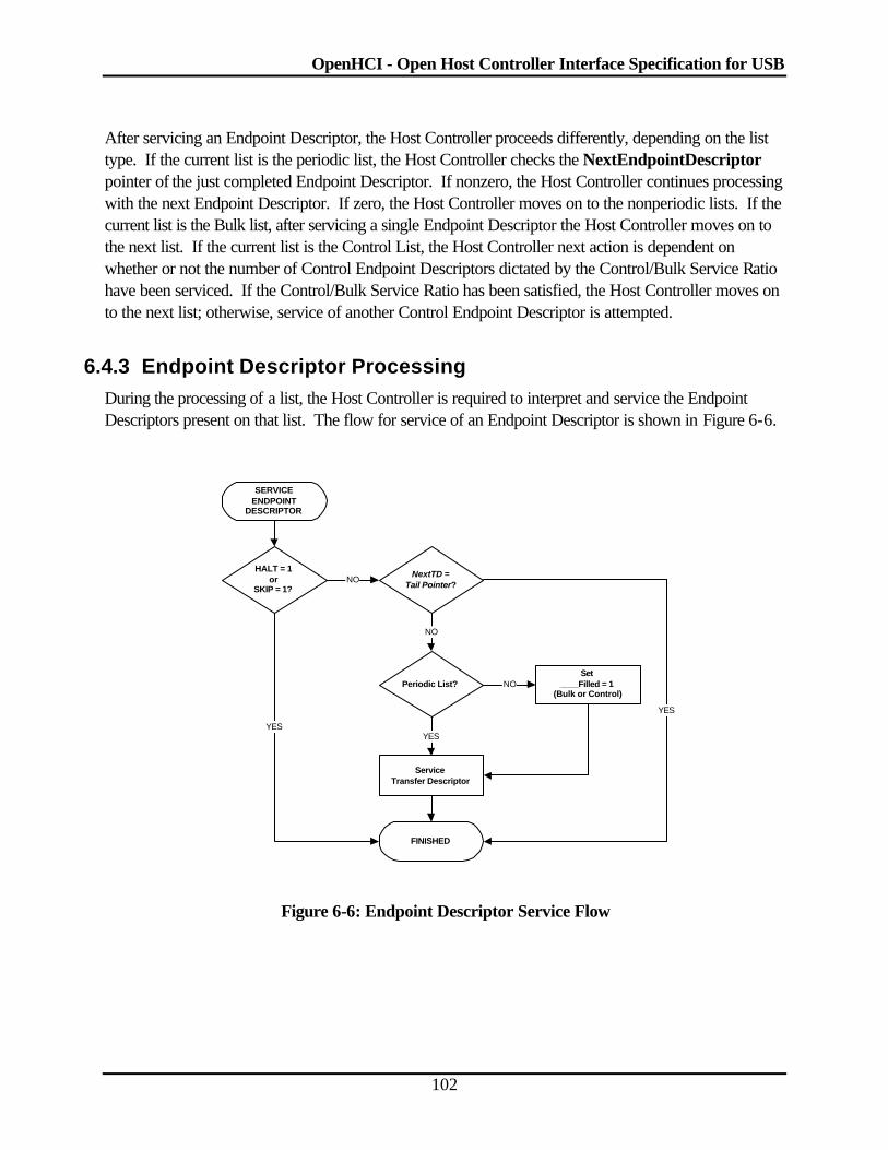
OpenHCI - Open Host Controller Interface Specification for USB
102
After servicing an Endpoint Descriptor, the Host Controller proceeds differently, depending on the list type. If the current list is the periodic list, the Host Controller checks the NextEndpointDescriptor pointer of the just completed Endpoint Descriptor. If nonzero, the Host Controller continues processing with the next Endpoint Descriptor. If zero, the Host Controller moves on to the nonperiodic lists. If the current list is the Bulk list, after servicing a single Endpoint Descriptor the Host Controller moves on to the next list. If the current list is the Control List, the Host Controller next action is dependent on whether or not the number of Control Endpoint Descriptors dictated by the Control/Bulk Service Ratio have been serviced. If the Control/Bulk Service Ratio has been satisfied, the Host Controller moves on to the next list; otherwise, service of another Control Endpoint Descriptor is attempted.
6.4.3 Endpoint Descriptor Processing During the processing of a list, the Host Controller is required to interpret and service the Endpoint Descriptors present on that list. The flow for service of an Endpoint Descriptor is shown in Figure 6-6.
SERVICEENDPOINT
DESCRIPTOR
ServiceTransfer Descriptor
NextTD =Tail Pointer?
HALT = 1or
SKIP = 1?NO
NO
FINISHED
YES
YES
Set____Filled = 1
(Bulk or Control)Periodic List?
YES
NO
Figure 6-6: Endpoint Descriptor Service Flow

OpenHCI - Open Host Controller Interface Specification for USB
103
When the Host Controller reads an Endpoint Descriptor, it first determines if the descriptor should be skipped. If either the sKip bit or the Halt bit in the Endpoint Descriptor is a ‘1,’ the Endpoint Descriptor is skipped and the Host Controller proceeds normally with the next Endpoint Descriptor or the next list. If the Endpoint Descriptor is not skipped, the Host Controller performs a check to determine if there is a Transfer Descriptor on the queue. If not, the Host Controller proceeds to the next Endpoint Descriptor or the next list. To determine if there is a Transfer Descriptor on the queue that can be processed, the Host Controller compares the Endpoint Descriptor’s TailPointer and NextTransferDescriptor fields. If the fields are different, there is a Transfer Descriptor available for processing. If they are equal, there is not a valid Transfer Descriptor on the list. If a valid Transfer Descriptor is present on the queue, the Host Controller attempts to service that Transfer Descriptor. Service of the Transfer Descriptor involves making only a single transaction attempt.
6.4.4 Transfer Descriptor Processing Transfer Descriptor processing is the fundamental operation performed by a Host Controller. The service flow for servicing a Transfer Descriptor is shown in Figure 6-7. The rest of this section describes the steps necessary for completing service of a Transfer Descriptor.
6.4.4.1 Isochronous Relative Frame Number Calculation
When processing an Isochronous Transfer Descriptor, the Host Controller must calculate the relative frame number. This calculation determines which, if any, packet will be sent during the current frame. This calculation is described in Section 4.3.2.1.
6.4.4.2 Packet Address and Size Calculation
When processing an Isochronous Transfer Descriptor, the relative frame number (R, calculated as described in Section 4.3.2.1) is used to select two offset values, Offset[R] and Offset[R+1]. If R is equal to the FrameCount field in the Transfer Descriptor, then Offset[R+1] is (BufferEnd+1). Offset[R] is subtracted from Offset[R+1] to get the size of the data buffer which should not be larger than MaximumPacketSize from the Endpoint Descriptor (this is not checked by the Host Controller and transmission problems occur if software violates this restriction). The initial address of the transfer is determined from Offset[R]. If bit 12 (the 13th LSb) of Offset[R] is 0, then the initial buffer address resides in the physical memory page specified in BufferPage0 of the Isochronous Transfer Descriptor. If bit 12 is 1, then the initial buffer address will reside in the physical page indicated by the upper 20 bits of BufferEnd. When the upper 20 bits are selected, the address is completed by using the low 12 bits of Offset[R] as the low 12 bits of the address. If bit 12 of both Offset[R] and Offset[R+1] are the same, then the packet transfer will not cross a page boundary. If they are different (only case is bit 12 of Offset[R] = 0 and bit 12 of Offset[R+1] = 1), then the packet transfer will cross a page boundary.
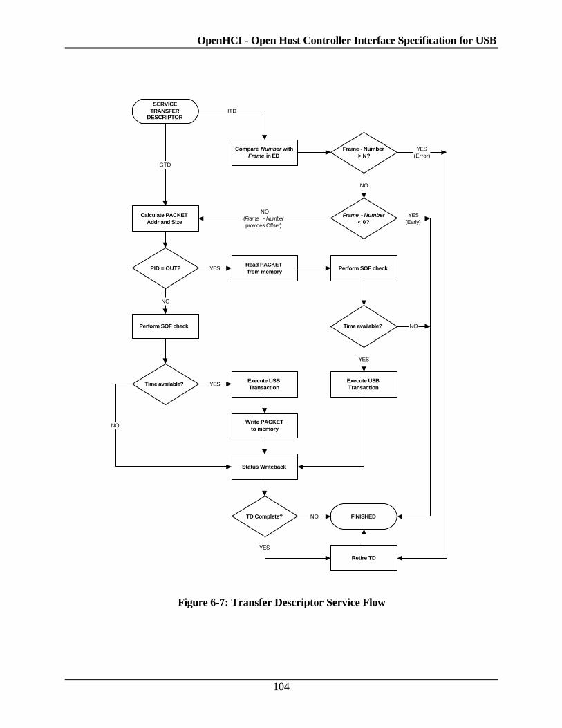
OpenHCI - Open Host Controller Interface Specification for USB
104
SERVICETRANSFER
DESCRIPTOR
Calculate PACKETAddr and Size
GTD
Perform SOF check Time available?
Execute USBTransaction
YES
Execute USBTransaction
Write PACKETto memory
Status Writeback
TD Complete?
Retire TD
NO FINISHED
YES
NO
PID = OUT?Read PACKETfrom memory
Perform SOF checkYES
NO
Time available? YES
NO
Frame - Number< 0?
Compare Number withFrame in ED
Frame - Number> N?
ITD
NO
NO(Frame - Numberprovides Offset)
YES(Error)
YES(Early)
Figure 6-7: Transfer Descriptor Service Flow

OpenHCI - Open Host Controller Interface Specification for USB
105
When the Host Controller fetches a General Transfer Descriptor, it gets the address of the next memory location be accessed from CurrentBufferPointer. If CurrentBufferPointer is 0, then the packet size will be zero, regardless of the setting of MaximumPacketSize in the Endpoint Descriptor. As the data is transferred to/from the CurrentBufferPointer address, the CurrentBufferPointer value might cross a page boundary. If it does, the upper 20 bits of BufferEnd are substituted for the current upper 20 bits of CurrentBufferPointer. This page boundary crossing may occur during a packet transfer (i.e., a single packet may cross a page boundary.) The maximum amount of data that will be sent to or accepted from the device is determined by the smaller of MaximumPacketSize in the Endpoint Descriptor or by the remaining buffer size (given by the General Transfer Descriptor). The remaining buffer size is found by subtracting the CurrentBufferPointer from BufferEnd. The subtraction may be performed by using two 13-bit terms A and B. The most significant bit of A is set to 0 if CurrentBufferPointer and BufferEnd are identical in their most significant 20 bits (i.e., they indicate the same physical page in memory) and set to 1 if they differ. The most significant bit of B is set to 0. The low order 12 bits of A and B are the low order 12 bits of BufferEnd and CurrentBufferPointer respectively. To the results of A - B add 1 to get the remaining space in the buffer.
6.4.4.3 Packet Transfer Time Check
Once the Host Controller determines a packet’s size, it must check to see if the packet transmission can occur over the USB before the end of the frame. This is determined by comparing the bit times remaining before the end of the frame with the bit time requirement of the packet to be transmitted. If the bit time requirement of the packet is larger than the bit times remaining in the frame, the transaction may not be initiated. This ensures that the Host Controller will never be responsible for causing a babble condition on the bus. For full speed transactions, the Host Controller uses the Largest Data Packet Counter to determine if a given packet can be transferred. For low speed transactions, regardless of the data size, the Host Controller compares the current value of the FrameRemaining field of HcFmRemaining with the value of the LSThreshold field of the HcLSThreshold register. If FrameRemaining is less than LSThreshold, the low speed transaction is not started on the bus.

OpenHCI - Open Host Controller Interface Specification for USB
106
6.4.4.4 Largest Data Packet Counter Operation
At each frame boundary, the Largest Data Packet Counter is loaded with the value of the FSLargestDataPacket field in HcFmInterval (at the same time FrameRemaining is loaded with the value of FrameInterval). For every 7 bit times on the bus, the counter is decremented by 6 because the number of useful bits does not diminish at the same rate as bus bit times pass due to bit stuffing. When the Host Controller loads a Transfer Descriptor, the worst case number of bit times for the data transfer on the bus is known. This value is simply the byte count multiplied by 8, using the MaximumPacketSize byte count for reads (the transaction overhead and the frame overhead are accounted for in the initial value of the counter). If the bit count required is greater than the remaining bit count in the Largest Data Packet Counter, the transfer is not started. When the transfer is not started, there is no status writeback to the Transfer Descriptor.
6.4.4.5 Status Writeback
At the completion of a transaction attempt, the Host Controller performs a status writeback to the Transfer Descriptor. The information written back differs depending on what type of Transfer Descriptor is being serviced.
6.4.4.5.1 General Transfer Descriptor Status Writeback
General Transfer Descriptors are updated after every attempted transaction. There are four fields that require updating after a transaction attempt. They are the CompletionCode field, the DataToggleControl field, the CurrentBufferPointer field, and occasionally the ErrorCount field. The DataToggleControl field must be updated to reflect the data toggle for the next transfer. If the packet just transmitted completed successfully, the Host Controller sets the MSb and toggles the LSb of DataToggleControl field to reflect a new value for the next packet. If the current packet did not complete with a proper ACK or NAK, the field should not be changed. The CurrentBufferPointer must be updated to reflect the amount of data transferred in the current packet if the transmission ended with a proper ACK or an error. If the Host Controller received an ACK or a NAK with an incorrect data toggle, the CurrentBufferPointer should not be updated because the Host Controller is required to retry the current packet. If the CurrentBufferPointer requires an update, the number of bytes transmitted in the packet should be added to the current value of the CurrentBufferPointer field. If the packet crossed a page boundary, the upper 20 bits of the CurrentBufferPointer should be updated with the upper 20 bits of the BufferEnd field to reflect the change in page base address. The lower 12 bits of the CurrentBufferPointer will roll over correctly with a normal addition to reflect the new packet address.

OpenHCI - Open Host Controller Interface Specification for USB
107
If there was an error in the packet transmission, the ErrorCount field must be incremented. If the ErrorCount is 2 and another error occurs, the Transfer Descriptor is retired with the error code reflected in the CompletionCode field. The CompletionCode field of a General Transfer Descriptor is updated after every attempted transaction whether successful or not. If the transaction was successful, the CompletionCode field will be set to “No Error.” Otherwise, it will be set according to the error type. When an endpoint returns a NAK handshake for a transmission, all General Transfer Descriptor fields will be the same after the transaction as they were when the transaction began. The Host Controller does not need to make any changes.
6.4.4.5.2 Isochronous Transfer Descriptor Status Writeback
The Host Controller updates the Offset[R] field after packet transmission using the Packet Status Word. For an OUT packet, the Size field is set to 0 if there is no error. For an IN, the Size field will reflect the actual number of bytes written to the memory buffer. Regardless of transfer direction, the CompletionCode field is updated to reflect the outcome of the transmission.
6.4.4.6 Transfer Descriptor Retirement
When a transfer descriptor is complete (all data sent/received) or an error condition occurs, the Transfer Descriptor must be retired. Several actions are required to retire a Transfer Descriptor. The Host Controller must place the Transfer Descriptor on the Done Queue and update the value of the Done Queue Interrupt Counter. In addition, the Host Controller must update the Endpoint Descriptor to reflect the changes to the NextTransferDescriptor pointer, the DataToggleCarry field, and potentially the Halt field. To dequeue the Transfer Descriptor, the Host Controller copies the current Transfer Descriptor’s NextTransferDescriptor field to the NextTransferDescriptor of the Endpoint Descriptor. Following the dequeuing of the Transfer Descriptor from the Endpoint Descriptor Queue, the Transfer Descriptor is enqueued to the Done Queue. To accomplish this, the Host Controller first writes the value of the HcDoneHead to the NextTransferDescriptor field of the Transfer Descriptor being enqueued. Second, the HcDoneHead is written with the address of the Transfer Descriptor being enqueued. The Host Controller must also update the DataToggleCarry field of the Endpoint Descriptor. The DataToggleCarry field should reflect the last data toggle value from the retired Transfer Descriptor. If the Transfer Descriptor is being retired because of an error, the Host Controller must update the Halt bit of the Endpoint Descriptor.

OpenHCI - Open Host Controller Interface Specification for USB
108
To complete the Transfer Descriptor retirement, the Host Controller updates the Done Queue Interrupt Counter. The InterruptDelay field of the Transfer Descriptor specifies the maximum number of SOFs that may occur before the Host Controller writes the HcDoneHead to the HCCA and generates an interrupt. If the value of the InterruptDelay field is 111b, the Host Controller Driver does not require an interrupt for the Transfer Descriptor and the Done Queue Interrupt Counter is left unchanged. If the value of the InterruptDelay field is not 111b, but is greater than or equal to the current value of the Done Queue Interrupt Counter, the counter is also left unchanged. In this case, another Transfer Descriptor already on the Done Queue requires an interrupt earlier than the Transfer Descriptor being retired. If the value of the InterruptDelay field is not 111b, but is less than the current value of the Done Queue Interrupt Counter, the counter is loaded with the value of the InterruptDelay field. In this case, the Transfer Descriptor being retired requires an interrupt earlier than all of the Transfer Descriptors currently on the Done Queue. If the Transfer Descriptor is being retired with an error, then the Done Queue Interrupt Counter is cleared as if the InterruptDelay field were zero.
6.4.5 Done Queue Occasionally (as determined by the Done Queue Interrupt Counter), when the Done Queue contains one or more Transfer Descriptors, the Host Controller writes the current value of HcDoneHead into the HccaDoneHead immediately following a frame boundary and generates an interrupt. These actions are taken so that the Host Controller Driver can complete the processing of retired Transfer Descriptors. After the HcDoneHead value is written to the HCCA, the Host Controller resets the value of HcDoneHead to ‘0’ and sets the WritebackDoneHead bit located in the HcInterruptStatus register to ‘1.’ While the WritebackDoneHead bit is set, the Host Controller may not write HcDoneHead to the HCCA. The WritebackDoneHead bit is cleared by the Host Controller Driver when it is ready to receive another Done Queue from the Host Controller.
6.4.5.1 Done Queue Interrupt Counter
The Host Controller maintains a 3-bit counter which is used to determine how often the HcDoneHead register value must be written to HccaDoneHead. The counter is initialized with a value of 111b at software reset, hardware reset, and when the Host Controller transitions to the USBOPERATIONAL state. The counter functions when the Host Controller is in the USBOPERATIONAL state by decrementing at every frame boundary simultaneous with the incrementing of the FrameNumber field in HcFmNumber if the current value of the counter is other than 111b or 0. If the current value of the counter is 111b or 0, the counter is effectively disabled and does not decrement.

OpenHCI - Open Host Controller Interface Specification for USB
109
The Host Controller checks the value of the counter during the last bit time of every frame when in the USBOPERATIONAL state. If the value of the counter is 0 at that time, the Host Controller checks the current value of the WritebackDoneHead bit in HcInterruptStatus. If WritebackDoneHead is ‘0,’ immediately following the frame boundary, the Host Controller writes the HcDoneHead register value to HccaDoneHead, sets WritebackDoneHead to ‘1,’ and resets the counter to 111b. If WritebackDoneHead is ‘1,’ the Host Controller takes no further action until the end of the next frame when it performs the same checks again.
6.5 Interrupt Processing Interrupts are the communication method for HC-initiated communication with the Host Controller Driver. There are several events which may trigger an interrupt from the Host Controller. Each specific event sets a specific bit in the HcInterruptStatus register. The Host Controller requests an interrupt when all three of the following conditions are met:
?? The MasterInterruptEnable bit in HcControl is set to ‘1’. ?? A bit in HcInterruptStatus is set to ‘1’. ?? The corresponding enable bit in HcInterruptEnable for the HcInterruptStatus bit is set to
‘1’. If the Host Controller supports an SMI pin, the interrupts caused by most events are routable, based on the value of the InterruptRouting bit of the HcControl register, to either the INT pin or the SMI pin. Enabled interrupt events causes an interrupt to be signaled on the INT pin when the InterruptRouting bit is a ‘0’ and signaled on the SMI pin if the InterruptRouting bit is a ‘1.’ However, OpenHCI Host Controllers are not required to implement an SMI pin. If a Host Controller does not implement an SMI pin and the InterruptRouting bit is a ‘1,’ interrupts are not generated. The notable exception for interrupt routing is the OwnershipChange event described in Section 6.5.8 which is always routed to the SMI pin. Each of the following subsections describes a specific event, and therefore a specific bit, represented in the HcInterruptStatus register.
6.5.1 SchedulingOverrun Event When a scheduling overrun occurs, the Host Controller sets the SchedulingOverrun bit following the completion of the next HccaFrameNumber update. A scheduling overrun occurs when the Host Controller determines that the Periodic list for the current frame cannot be completed before the end of the frame.

OpenHCI - Open Host Controller Interface Specification for USB
110
6.5.2 WritebackDoneHead Event Periodically, the Host Controller is required to update HccaDoneHead with the value of the HcDoneHead register (see Section 6.4.5). When the write of HcDoneHead to HccaDoneHead completes, the Host Controller sets the WritebackDoneHead bit. The corresponding interrupt (if enabled) will inform the Host Controller Driver that it must service the Done Queue.
6.5.3 StartOfFrame Event When FrameRemaining is loaded with FrameInterval, the Host Controller sets the StartOfFrame bit following completion of the next HccaFrameNumber update. This corresponds to a frame boundary. The Host Controller Driver will normally disable this event, enabling the event when it requires a deterministic interrupt at a frame boundary.
6.5.4 ResumeDetected Event A resume detected event occurs when the Root Hub detects resume signaling on the USB bus. The Host Controller will set the ResumeDetected bit when resume signaling is detected. A ResumeDetected interrupt is only possible in the USBSUSPEND state. A resume event can be either an upstream resume signal or a connect/disconnect detection at a port. The connect/ disconnect resume event is enabled by the RemoteWakeupEnable in the HcRhStatus register. If a port is either in the progress of selectively resuming or has completed the selective resume and set PortSuspendStatusChange when the Root Hub enters the USBSUSPEND state, the port resume is cleared and the hub resume, ResumeDetected, is generated. Note: A ResumeDetected interrupt corresponds to hardware initiated USBSUSPEND to USBRESUME
transition.
6.5.5 UnrecoverableError Event The Host Controller sets the UnrecoverableError bit when it detects a system error not related to USB or an error that cannot be reported in any other way.
6.5.6 FrameNumberOverflow Event When the MSb (bit 15) of the FrameNumber field of HcFmNumber changes value, the FrameNumberOverflow bit is set by the Host Controller following the next HccaFrameNumber update. The event occurs on both the ‘1’ to ‘0’ or the ‘0’ to ‘1’ transition. This event allows the Host Controller Driver to perform any necessary manipulation of its software based frame number to ensure that number is correct.
OpenHCI - Open Host Controller Interface Specification for USB
111
6.5.7 RootHubStatusChange Event The Host Controller sets the RootHubStatusChange bit whenever there is a change to any bit in HcRhStatus or HcRhPortStatus. Any changes in these registers define a change in status that must be communicated to the Host Controller Driver. Since OpenHCI provides a register-level interface to the Root Hub, the need for Root Hub Transfer Descriptors is eliminated. This provides for a more efficient Root Hub interface, but does not provide the Host Controller Driver a good mechanism for polling the Root Hub on a periodic basis. To compensate for the lack of a good polling mechanism, the Host Controller delivers an interrupt on every Root Hub status change.
6.5.8 OwnershipChange Event The OwnershipChange bit is set by the Host Controller when the Host Controller Driver sets the OwnershipChangeRequest bit in the HcCommandStatus register. This ensures that an interrupt is generated (unless it is masked) whenever ownership of the Host Controller is passed to and from the operating system’s Host Controller Driver and any SMM-based Host Controller Driver in the system. All interrupts resulting from an OwnershipChange event are not routable with the InterruptRouting bit of the HcControl register and are delivered on the SMI pin only. If the Host Controller does not implement an SMI pin, interrupts will not be generated at all on an OwnershipChange event.
6.6 Root Hub The Root Hub functional operation is defined by the USB Specification. The OpenHCI Specification only defines a register-level interface which the HCD uses to emulate standard hub endpoint communication. See chapter 7 for a description of the register interface definition. The Root Hub USB reset and resume signaling are controlled by the HostControllerFunctionalState bits. The HCD is responsible for all timing associated with these operations. The port reset and resume signal timing is controlled by the hardware.
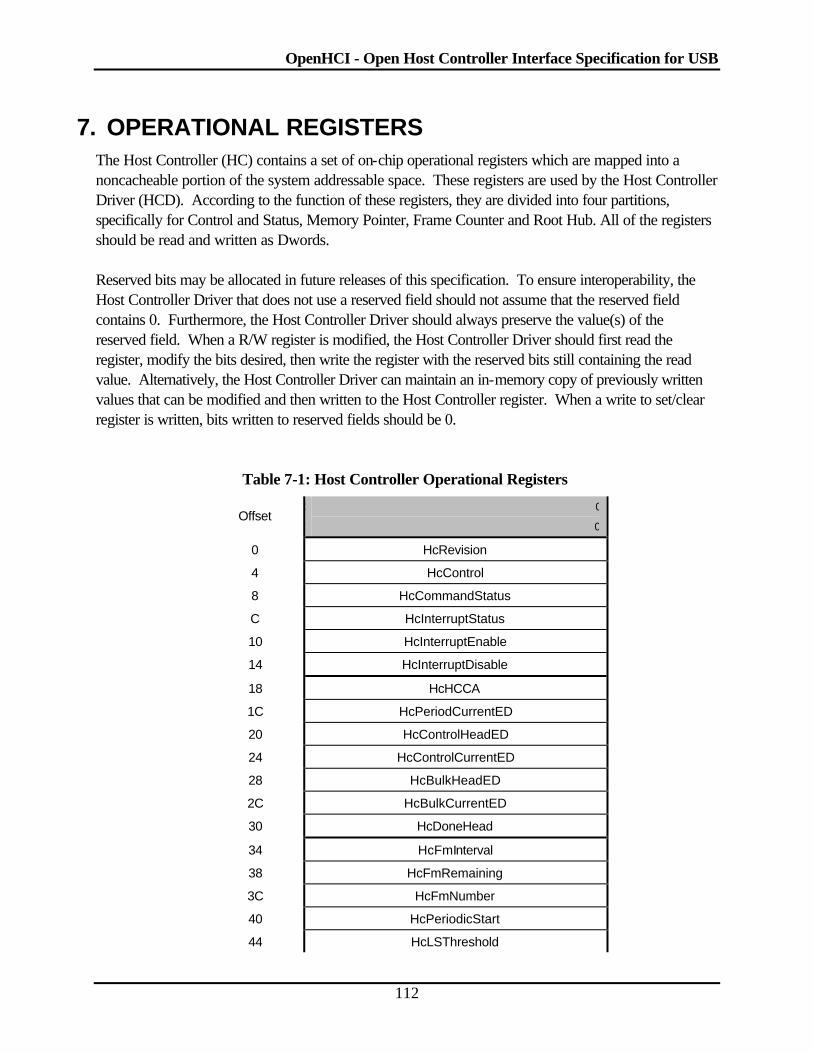
OpenHCI - Open Host Controller Interface Specification for USB
112
7. OPERATIONAL REGISTERS The Host Controller (HC) contains a set of on-chip operational registers which are mapped into a noncacheable portion of the system addressable space. These registers are used by the Host Controller Driver (HCD). According to the function of these registers, they are divided into four partitions, specifically for Control and Status, Memory Pointer, Frame Counter and Root Hub. All of the registers should be read and written as Dwords. Reserved bits may be allocated in future releases of this specification. To ensure interoperability, the Host Controller Driver that does not use a reserved field should not assume that the reserved field contains 0. Furthermore, the Host Controller Driver should always preserve the value(s) of the reserved field. When a R/W register is modified, the Host Controller Driver should first read the register, modify the bits desired, then write the register with the reserved bits still containing the read value. Alternatively, the Host Controller Driver can maintain an in-memory copy of previously written values that can be modified and then written to the Host Controller register. When a write to set/clear register is written, bits written to reserved fields should be 0.
Table 7-1: Host Controller Operational Registers
Offset
3 0
1 0
0 HcRevision
4 HcControl
8 HcCommandStatus
C HcInterruptStatus
10 HcInterruptEnable
14 HcInterruptDisable
18 HcHCCA
1C HcPeriodCurrentED
20 HcControlHeadED
24 HcControlCurrentED
28 HcBulkHeadED
2C HcBulkCurrentED
30 HcDoneHead
34 HcFmInterval
38 HcFmRemaining
3C HcFmNumber
40 HcPeriodicStart
44 HcLSThreshold

OpenHCI - Open Host Controller Interface Specification for USB
113
Table 7-1: Host Controller Operational Registers
Offset
3 0
1 0
48 HcRhDescriptorA
4C HcRhDescriptorB
50 HcRhStatus
54 HcRhPortStatus[1]
... ...
54+4*NDP HcRhPortStatus[NDP]
7.1 The Control and Status Partition 7.1.1 HcRevision Register
3 0 0 0 1 8 7 0
reserved REV
Figure 7-1: HcRevision Register
Read/Write
Key Reset HCD HC Description
REV 10h R R Revision This read-only field contains the BCD representation of the version of the HCI specification that is implemented by this HC. For example, a value of 11h corresponds to version 1.1. All of the HC implementations that are compliant with this specification will have a value of 10h.
7.1.2 HcControl Register
The HcControl register defines the operating modes for the Host Controller. Most of the fields in this register are modified only by the Host Controller Driver, except HostControllerFunctionalState and RemoteWakeupConnected.
3 1 1 0 0 0 0 0 0 0 0 0 0 1 1 0 9 8 7 6 5 4 3 2 1 0
reserved
R W E
R WC
I R
H C F S
B L E
C L E
I E
P L E
C B S R
Figure 7-2: HcControl Register

OpenHCI - Open Host Controller Interface Specification for USB
114
Read/Write
Key Reset HCD HC Description
CBSR 00b R/W R ControlBulkServiceRatio This specifies the service ratio between Control and Bulk EDs. Before processing any of the nonperiodic lists, HC must compare the ratio specified with its internal count on how many nonempty Control EDs have been processed, in determining whether to continue serving another Control ED or switching to Bulk EDs. The internal count will be retained when crossing the frame boundary. In case of reset, HCD is responsible for restoring this value.
CBSR No. of Control EDs Over Bulk EDs Served0 1 : 11 2 : 12 3 : 13 4 : 1
PLE 0b R/W R PeriodicListEnable
This bit is set to enable the processing of the periodic list in the next Frame. If cleared by HCD, processing of the periodic list does not occur after the next SOF. HC must check this bit before it starts processing the list.
IE 0b R/W R IsochronousEnable This bit is used by HCD to enable/disable processing of isochronous EDs. While processing the periodic list in a Frame, HC checks the status of this bit when it finds an Isochronous ED (F=1). If set (enabled), HC continues processing the EDs. If cleared (disabled), HC halts processing of the periodic list (which now contains only isochronous EDs) and begins processing the Bulk/Control lists. Setting this bit is guaranteed to take effect in the next Frame (not the current Frame).
CLE 0b R/W R ControlListEnable This bit is set to enable the processing of the Control list in the next Frame. If cleared by HCD, processing of the Control list does not occur after the next SOF. HC must check this bit whenever it determines to process the list. When disabled, HCD may modify the list. If HcControlCurrentED is pointing to an ED to be removed, HCD must advance the pointer by updating HcControlCurrentED before re-enabling processing of the list.
BLE 0b R/W R BulkListEnable This bit is set to enable the processing of the Bulk list in the next Frame. If cleared by HCD, processing of the Bulk list does not occur after the next SOF. HC checks this bit whenever it determines to process the list. When disabled, HCD may modify the list. If HcBulkCurrentED is pointing to an ED to be removed, HCD must advance the pointer by updating HcBulkCurrentED before re-enabling processing of the list.

OpenHCI - Open Host Controller Interface Specification for USB
115
Read/Write
Key Reset HCD HC Description
HCFS 00b R/W R/W HostControllerFunctionalState for USB 00b: USBRESET 01b: USBRESUME 10b: USBOPERATIONAL 11b: USBSUSPEND A transition to USBOPERATIONAL from another state causes SOF generation to begin 1 ms later. HCD may determine whether HC has begun sending SOFs by reading the StartofFrame field of HcInterruptStatus. This field may be changed by HC only when in the USBSUSPEND state. HC may move from the USBSUSPEND state to the USBRESUME state after detecting the resume signaling from a downstream port. HC enters USBSUSPEND after a software reset, whereas it enters USBRESET after a hardware reset. The latter also resets the Root Hub and asserts subsequent reset signaling to downstream ports.
IR 0b R/W R InterruptRouting This bit determines the routing of interrupts generated by events registered in HcInterruptStatus. If clear, all interrupts are routed to the normal host bus interrupt mechanism. If set, interrupts are routed to the System Management Interrupt. HCD clears this bit upon a hardware reset, but it does not alter this bit upon a software reset. HCD uses this bit as a tag to indicate the ownership of HC.
RWC 0b R/W R/W RemoteWakeupConnected This bit indicates whether HC supports remote wakeup signaling. If remote wakeup is supported and used by the system it is the responsibility of system firmware to set this bit during POST. HC clears the bit upon a hardware reset but does not alter it upon a software reset. Remote wakeup signaling of the host system is host-bus-specific and is not described in this specification.
RWE 0b R/W R RemoteWakeupEnable This bit is used by HCD to enable or disable the remote wakeup feature upon the detection of upstream resume signaling. When this bit is set and the ResumeDetected bit in HcInterruptStatus is set, a remote wakeup is signaled to the host system. Setting this bit has no impact on the generation of hardware interrupt.

OpenHCI - Open Host Controller Interface Specification for USB
116
7.1.3 HcCommandStatus Register
The HcCommandStatus register is used by the Host Controller to receive commands issued by the Host Controller Driver, as well as reflecting the current status of the Host Controller. To the Host Controller Driver, it appears to be a "write to set" register. The Host Controller must ensure that bits written as ‘1’ become set in the register while bits written as ‘0’ remain unchanged in the register. The Host Controller Driver may issue multiple distinct commands to the Host Controller without concern for corrupting previously issued commands. The Host Controller Driver has normal read access to all bits. The SchedulingOverrunCount field indicates the number of frames with which the Host Controller has detected the scheduling overrun error. This occurs when the Periodic list does not complete before EOF. When a scheduling overrun error is detected, the Host Controller increments the counter and sets the SchedulingOverrun field in the HcInterruptStatus register.
3 1 1 1 1 0 0 0 0 0 1 8 7 6 5 4 3 2 1 0
reserved
S O C
reserved
O C R
B L F
C L F
H C R
Figure 7-3: HcCommandStatus Register
Read/Write
Key Reset HCD HC Description
HCR 0b R/W R/W HostControllerReset This bit is set by HCD to initiate a software reset of HC. Regardless of the functional state of HC, it moves to the USBSUSPEND state in which most of the operational registers are reset except those stated otherwise; e.g., the InterruptRouting field of HcControl, and no Host bus accesses are allowed. This bit is cleared by HC upon the completion of the reset operation. The reset operation must be completed within 10 ?s. This bit, when set, should not cause a reset to the Root Hub and no subsequent reset signaling should be asserted to its downstream ports.

OpenHCI - Open Host Controller Interface Specification for USB
117
Read/Write
Key Reset HCD HC Description
CLF 0b R/W R/W ControlListFilled This bit is used to indicate whether there are any TDs on the Control list. It is set by HCD whenever it adds a TD to an ED in the Control list. When HC begins to process the head of the Control list, it checks CLF. As long as ControlListFilled is 0, HC will not start processing the Control list. If CF is 1, HC will start processing the Control list and will set ControlListFilled to 0. If HC finds a TD on the list, then HC will set ControlListFilled to 1 causing the Control list processing to continue. If no TD is found on the Control list, and if the HCD does not set ControlListFilled, then ControlListFilled will still be 0 when HC completes processing the Control list and Control list processing will stop.
BLF 0b R/W R/W BulkListFilled This bit is used to indicate whether there are any TDs on the Bulk list. It is set by HCD whenever it adds a TD to an ED in the Bulk list. When HC begins to process the head of the Bulk list, it checks BF. As long as BulkListFilled is 0, HC will not start processing the Bulk list. If BulkListFilled is 1, HC will start processing the Bulk list and will set BF to 0. If HC finds a TD on the list, then HC will set BulkListFilled to 1 causing the Bulk list processing to continue. If no TD is found on the Bulk list, and if HCD does not set BulkListFilled, then BulkListFilled will still be 0 when HC completes processing the Bulk list and Bulk list processing will stop.
OCR 0b R/W R/W OwnershipChangeRequest This bit is set by an OS HCD to request a change of control of the HC. When set HC will set the OwnershipChange field in HcInterruptStatus. After the changeover, this bit is cleared and remains so until the next request from OS HCD.
SOC 00b R R/W SchedulingOverrunCount These bits are incremented on each scheduling overrun error. It is initialized to 00b and wraps around at 11b. This will be incremented when a scheduling overrun is detected even if SchedulingOverrun in HcInterruptStatus has already been set. This is used by HCD to monitor any persistent scheduling problems.
7.1.4 HcInterruptStatus Register
This register provides status on various events that cause hardware interrupts. When an event occurs, Host Controller sets the corresponding bit in this register. When a bit becomes set, a hardware interrupt is generated if the interrupt is enabled in the HcInterruptEnable register (see Section 7.1.5) and the MasterInterruptEnable bit is set. The Host Controller Driver may clear specific bits in this register by writing ‘1’ to bit positions to be cleared. The Host Controller Driver may not set any of these bits. The Host Controller will never clear the bit.

OpenHCI - Open Host Controller Interface Specification for USB
118
3 3 2 0 0 0 0 0 0 0 0 1 0 9 7 6 5 4 3 2 1 0
0 O C
reserved
R
H S C
F N O
U E
R D
S F
WD H
S O
Figure 7-4: HcInterruptStatus Register
Read/Write
Key Reset HCD HC Description
SO 0b R/W R/W SchedulingOverrun This bit is set when the USB schedule for the current Frame overruns and after the update of HccaFrameNumber. A scheduling overrun will also cause the SchedulingOverrunCount of HcCommandStatus to be incremented.
WDH 0b R/W R/W WritebackDoneHead This bit is set immediately after HC has written HcDoneHead to HccaDoneHead. Further updates of the HccaDoneHead will not occur until this bit has been cleared. HCD should only clear this bit after it has saved the content of HccaDoneHead.
SF 0b R/W R/W StartofFrame This bit is set by HC at each start of a frame and after the update of HccaFrameNumber. HC also generates a SOF token at the same time.
RD 0b R/W R/W ResumeDetected This bit is set when HC detects that a device on the USB is asserting resume signaling. It is the transition from no resume signaling to resume signaling causing this bit to be set. This bit is not set when HCD sets the USBRESUME state.
UE 0b R/W R/W UnrecoverableError This bit is set when HC detects a system error not related to USB. HC should not proceed with any processing nor signaling before the system error has been corrected. HCD clears this bit after HC has been reset.

OpenHCI - Open Host Controller Interface Specification for USB
119
Read/Write
Key Reset HCD HC Description
FNO 0b R/W R/W FrameNumberOverflow This bit is set when the MSb of HcFmNumber (bit 15) changes value, from 0 to 1 or from 1 to 0, and after HccaFrameNumber has been updated.
RHSC 0b R/W R/W RootHubStatusChange This bit is set when the content of HcRhStatus or the content of any of HcRhPortStatus[NumberofDownstreamPort] has changed.
OC 0b R/W R/W OwnershipChange This bit is set by HC when HCD sets the OwnershipChangeRequest field in HcCommandStatus. This event, when unmasked, will always generate an System Management Interrupt (SMI) immediately. This bit is tied to 0b when the SMI pin is not implemented.

OpenHCI - Open Host Controller Interface Specification for USB
120
7.1.5 HcInterruptEnable Register
Each enable bit in the HcInterruptEnable register corresponds to an associated interrupt bit in the HcInterruptStatus register. The HcInterruptEnable register is used to control which events generate a hardware interrupt. When a bit is set in the HcInterruptStatus register AND the corresponding bit in the HcInterruptEnable register is set AND the MasterInterruptEnable bit is set, then a hardware interrupt is requested on the host bus. Writing a '1' to a bit in this register sets the corresponding bit, whereas writing a '0' to a bit in this register leaves the corresponding bit unchanged. On read, the current value of this register is returned.
3 3 2 0 0 0 0 0 0 0 0 1 0 9 7 6 5 4 3 2 1 0
M I E
O C
reserved
R
H S C
F N O
U E
R D
S F
WD H
S O
Figure 7-5: HcInterruptEnable Register
Read/Write
Key Reset HCD HC Description
SO 0b R/W R 0 - Ignore 1 - Enable interrupt generation due to Scheduling Overrun.
WDH 0b R/W R 0 - Ignore 1 - Enable interrupt generation due to HcDoneHead Writeback.
SF 0b R/W R 0 - Ignore 1 - Enable interrupt generation due to Start of Frame.
RD 0b R/W R 0 - Ignore 1 - Enable interrupt generation due to Resume Detect.
UE 0b R/W R 0 - Ignore 1 - Enable interrupt generation due to Unrecoverable Error.
FNO 0b R/W R 0 - Ignore 1 - Enable interrupt generation due to Frame Number Overflow.
RHSC 0b R/W R 0 - Ignore 1 - Enable interrupt generation due to Root Hub Status Change.
OC 0b R/W R 0 - Ignore 1 - Enable interrupt generation due to Ownership Change.
MIE 0b R/W R A ‘0’ written to this field is ignored by HC. A '1' written to this field enables interrupt generation due to events specified in the other bits of this register. This is used by HCD as a Master Interrupt Enable.
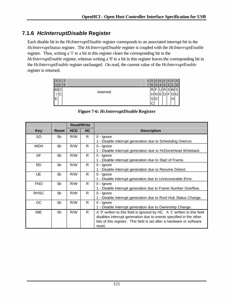
OpenHCI - Open Host Controller Interface Specification for USB
121
7.1.6 HcInterruptDisable Register
Each disable bit in the HcInterruptDisable register corresponds to an associated interrupt bit in the HcInterruptStatus register. The HcInterruptDisable register is coupled with the HcInterruptEnable register. Thus, writing a '1' to a bit in this register clears the corresponding bit in the HcInterruptEnable register, whereas writing a '0' to a bit in this register leaves the corresponding bit in the HcInterruptEnable register unchanged. On read, the current value of the HcInterruptEnable register is returned.
3 3 2 0 0 0 0 0 0 0 0 1 0 9 7 6 5 4 3 2 1 0
M I E
O C
reserved
R
H S C
F N O
U E
R D
S F
WD H
S O
Figure 7-6: HcInterruptDisable Register
Read/Write
Key Reset HCD HC Description
SO 0b R/W R 0 - Ignore 1 - Disable interrupt generation due to Scheduling Overrun.
WDH 0b R/W R 0 - Ignore 1 - Disable interrupt generation due to HcDoneHead Writeback.
SF 0b R/W R 0 - Ignore 1 - Disable interrupt generation due to Start of Frame.
RD 0b R/W R 0 - Ignore 1 - Disable interrupt generation due to Resume Detect.
UE 0b R/W R 0 - Ignore 1 - Disable interrupt generation due to Unrecoverable Error.
FNO 0b R/W R 0 - Ignore 1 - Disable interrupt generation due to Frame Number Overflow.
RHSC 0b R/W R 0 - Ignore 1 - Disable interrupt generation due to Root Hub Status Change.
OC 0b R/W R 0 - Ignore 1 - Disable interrupt generation due to Ownership Change.
MIE 0b R/W R A '0' written to this field is ignored by HC. A '1' written to this field disables interrupt generation due to events specified in the other bits of this register. This field is set after a hardware or software reset.
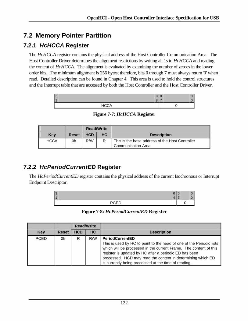
OpenHCI - Open Host Controller Interface Specification for USB
122
7.2 Memory Pointer Partition
7.2.1 HcHCCA Register
The HcHCCA register contains the physical address of the Host Controller Communication Area. The Host Controller Driver determines the alignment restrictions by writing all 1s to HcHCCA and reading the content of HcHCCA. The alignment is evaluated by examining the number of zeroes in the lower order bits. The minimum alignment is 256 bytes; therefore, bits 0 through 7 must always return '0' when read. Detailed description can be found in Chapter 4. This area is used to hold the control structures and the Interrupt table that are accessed by both the Host Controller and the Host Controller Driver.
3 0 0 0 1 8 7 0
HCCA 0
Figure 7-7: HcHCCA Register
Read/Write
Key Reset HCD HC Description
HCCA 0h R/W R This is the base address of the Host Controller Communication Area.
7.2.2 HcPeriodCurrentED Register
The HcPeriodCurrentED register contains the physical address of the current Isochronous or Interrupt Endpoint Descriptor.
3 0 0 0 1 4 3 0
PCED 0
Figure 7-8: HcPeriodCurrentED Register
Read/Write
Key Reset HCD HC Description
PCED 0h R R/W PeriodCurrentED This is used by HC to point to the head of one of the Periodic lists which will be processed in the current Frame. The content of this register is updated by HC after a periodic ED has been processed. HCD may read the content in determining which ED is currently being processed at the time of reading.

OpenHCI - Open Host Controller Interface Specification for USB
123
7.2.3 HcControlHeadED Register
The HcControlHeadED register contains the physical address of the first Endpoint Descriptor of the Control list.
3 0 0 0 1 4 3 0
CHED 0
Figure 7-9: HcControlHeadED Register
Read/Write
Key Reset HCD HC Description
CHED 0h R/W R ControlHeadED HC traverses the Control list starting with the HcControlHeadED pointer. The content is loaded from HCCA during the initialization of HC.
7.2.4 HcControlCurrentED Register
The HcControlCurrentED register contains the physical address of the current Endpoint Descriptor of the Control list.
3 0 0 0 1 4 3 0
CCED 0
Figure 7-10: HcControlCurrentED Register
Read/Write
Key Reset HCD HC Description
CCED 0h R/W R/W ControlCurrentED This pointer is advanced to the next ED after serving the present one. HC will continue processing the list from where it left off in the last Frame. When it reaches the end of the Control list, HC checks the ControlListFilled of in HcCommandStatus. If set, it copies the content of HcControlHeadED to HcControlCurrentED and clears the bit. If not set, it does nothing. HCD is allowed to modify this register only when the ControlListEnable of HcControl is cleared. When set, HCD only reads the instantaneous value of this register. Initially, this is set to zero to indicate the end of the Control list.

OpenHCI - Open Host Controller Interface Specification for USB
124
7.2.5 HcBulkHeadED Register
The HcBulkHeadED register contains the physical address of the first Endpoint Descriptor of the Bulk list.
3 0 0 0 1 4 3 0
BHED 0
Figure 7-11: HcBulkHeadED Register
Read/Write
Key Reset HCD HC Description
BHED 0h R/W R BulkHeadED HC traverses the Bulk list starting with the HcBulkHeadED pointer. The content is loaded from HCCA during the initialization of HC.
7.2.6 HcBulkCurrentED Register
The HcBulkCurrentED register contains the physical address of the current endpoint of the Bulk list. As the Bulk list will be served in a round-robin fashion, the endpoints will be ordered according to their insertion to the list.
3 0 0 0 1 4 3 0
BCED 0
Figure 7-12: HcBulkCurrentED Register
Read/Write
Key Reset HCD HC Description
BCED 0h R/W R/W BulkCurrentED This is advanced to the next ED after the HC has served the present one. HC continues processing the list from where it left off in the last Frame. When it reaches the end of the Bulk list, HC checks the ControlListFilled of HcControl. If set, it copies the content of HcBulkHeadED to HcBulkCurrentED and clears the bit. If it is not set, it does nothing. HCD is only allowed to modify this register when the BulkListEnable of HcControl is cleared. When set, the HCD only reads the instantaneous value of this register. This is initially set to zero to indicate the end of the Bulk list.
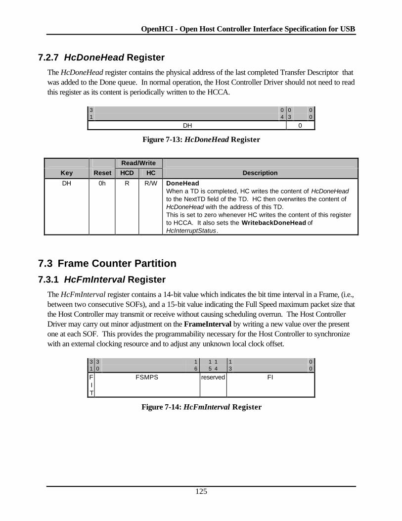
OpenHCI - Open Host Controller Interface Specification for USB
125
7.2.7 HcDoneHead Register
The HcDoneHead register contains the physical address of the last completed Transfer Descriptor that was added to the Done queue. In normal operation, the Host Controller Driver should not need to read this register as its content is periodically written to the HCCA.
3 0 0 0 1 4 3 0
DH 0
Figure 7-13: HcDoneHead Register
Read/Write
Key Reset HCD HC Description
DH 0h R R/W DoneHead When a TD is completed, HC writes the content of HcDoneHead to the NextTD field of the TD. HC then overwrites the content of HcDoneHead with the address of this TD. This is set to zero whenever HC writes the content of this register to HCCA. It also sets the WritebackDoneHead of HcInterruptStatus.
7.3 Frame Counter Partition
7.3.1 HcFmInterval Register
The HcFmInterval register contains a 14-bit value which indicates the bit time interval in a Frame, (i.e., between two consecutive SOFs), and a 15-bit value indicating the Full Speed maximum packet size that the Host Controller may transmit or receive without causing scheduling overrun. The Host Controller Driver may carry out minor adjustment on the FrameInterval by writing a new value over the present one at each SOF. This provides the programmability necessary for the Host Controller to synchronize with an external clocking resource and to adjust any unknown local clock offset.
3 3 1 1 1 1 0 1 0 6 5 4 3 0
F I T
FSMPS reserved FI
Figure 7-14: HcFmInterval Register

OpenHCI - Open Host Controller Interface Specification for USB
126
Read/Write
Key Reset HCD HC Description
FI 2EDFh R/W R FrameInterval This specifies the interval between two consecutive SOFs in bit times. The nominal value is set to be 11,999. HCD should store the current value of this field before resetting HC. By setting the HostControllerReset field of HcCommandStatus as this will cause the HC to reset this field to its nominal value. HCD may choose to restore the stored value upon the completion of the Reset sequence.
FSMPS TBD R/W R FSLargestDataPacket This field specifies a value which is loaded into the Largest Data Packet Counter at the beginning of each frame. The counter value represents the largest amount of data in bits which can be sent or received by the HC in a single transaction at any given time without causing scheduling overrun. The field value is calculated by the HCD.
FIT 0b R/W R FrameIntervalToggle HCD toggles this bit whenever it loads a new value to FrameInterval.
7.3.2 HcFmRemaining Register
The HcFmRemaining register is a 14-bit down counter showing the bit time remaining in the current Frame.
3 3 1 1 0 1 0 4 3 0
F R T
reserved FR
Figure 7-15: HcFmRemaining Register
Read/Write
Key Reset HCD HC Description
FR 0h R R/W FrameRemaining This counter is decremented at each bit time. When it reaches zero, it is reset by loading the FrameInterval value specified in HcFmInterval at the next bit time boundary. When entering the USBOPERATIONAL state, HC re-loads the content with the FrameInterval of HcFmInterval and uses the updated value from the next SOF.
FRT 0b R R/W FrameRemainingToggle This bit is loaded from the FrameIntervalToggle field of HcFmInterval whenever FrameRemaining reaches 0. This bit is used by HCD for the synchronization between FrameInterval and FrameRemaining.

OpenHCI - Open Host Controller Interface Specification for USB
127
7.3.3 HcFmNumber Register
The HcFmNumber register is a 16-bit counter. It provides a timing reference among events happening in the Host Controller and the Host Controller Driver. The Host Controller Driver may use the 16-bit value specified in this register and generate a 32-bit frame number without requiring frequent access to the register.
3 1 1 0 1 6 5 0
reserved FN
Figure 7-16: HcFmNumber Register
Read/Write
Key Reset HCD HC Description
FN 0h R R/W FrameNumber This is incremented when HcFmRemaining is re-loaded. It will be rolled over to 0h after ffffh. When entering the USBOPERATIONAL state, this will be incremented automatically. The content will be written to HCCA after HC has incremented the FrameNumber at each frame boundary and sent a SOF but before HC reads the first ED in that Frame. After writing to HCCA, HC will set the StartofFrame in HcInterruptStatus.
7.3.4 HcPeriodicStart Register
The HcPeriodicStart register has a 14-bit programmable value which determines when is the earliest time HC should start processing the periodic list.
3 1 1 0 1 4 3 0
reserved PS
Figure 7-17: HcPeriodicStart Register
Read/Write
Key Reset HCD HC Description
PS 0h R/W R PeriodicStart After a hardware reset, this field is cleared. This is then set by HCD during the HC initialization. The value is calculated roughly as 10% off from HcFmInterval.. A typical value will be 3E67h. When HcFmRemaining reaches the value specified, processing of the periodic lists will have priority over Control/Bulk processing. HC will therefore start processing the Interrupt list after completing the current Control or Bulk transaction that is in progress.

OpenHCI - Open Host Controller Interface Specification for USB
128
7.3.5 HcLSThreshold Register
The HcLSThreshold register contains an 11-bit value used by the Host Controller to determine whether to commit to the transfer of a maximum of 8-byte LS packet before EOF. Neither the Host Controller nor the Host Controller Driver are allowed to change this value.
3 1 1 0 1 2 1 0
reserved LST
Figure 7-18: HcLSThreshold Register
Read/Write
Key Reset HCD HC Description
LST 0628h R/W R LSThreshold This field contains a value which is compared to the FrameRemaining field prior to initiating a Low Speed transaction. The transaction is started only if FrameRemaining ? this field. The value is calculated by HCD with the consideration of transmission and setup overhead.
7.4 Root Hub Partition All registers included in this partition are dedicated to the USB Root Hub which is an integral part of the Host Controller though still a functionally separate entity. The HCD emulates USBD accesses to the Root Hub via a register interface. The HCD maintains many USB-defined hub features which are not required to be supported in hardware. For example, the Hub's Device, Configuration, Interface, and Endpoint Descriptors are maintained only in the HCD as well as some static fields of the Class Descriptor. The HCD also maintains and decodes the Root Hub's device address as well as other trivial operations which are better suited to software than hardware. The Root Hub register interface is otherwise developed to maintain similarity of bit organization and operation to typical hubs which are found in the system. Below are four register definitions: HcRhDescriptorA, HcRhDescriptorB, HcRhStatus, and HcRhPortStatus[1:NDP]. Each register is read and written as a Dword. These registers are only written during initialization to correspond with the system implementation. The HcRhDescriptorA and HcRhDescriptorB registers should be implemented such that they are writeable regardless of the HC USB state. HcRhStatus and HcRhPortStatus must be writeable during the USBOPERATIONAL state. Note: IS denotes an implementation-specific reset value for that field.

OpenHCI - Open Host Controller Interface Specification for USB
129
7.4.1 HcRhDescriptorA Register
The HcRhDescriptorA register is the first register of two describing the characteristics of the Root Hub. Reset values are implementation-specific. The descriptor length (11), descriptor type (TBD), and hub controller current (0) fields of the hub Class Descriptor are emulated by the HCD. All other fields are located in the HcRhDescriptorA and HcRhDescriptorB registers.
3 2 2 1 1 1 1 0 0 0 0 1 4 3 3 2 1 0 9 8 7 0
POTPGT Reserved N O C P
O C P M
D T
N P S
P S M
NDP
Figure 7-19: HcRhDescriptorA Register
Power
On Read/Write
Field Reset HCD HC Description
NDP IS R R NumberDownstreamPorts These bits specify the number of downstream ports supported by the Root Hub. It is implementation-specific. The minimum number of ports is 1. The maximum number of ports supported by OpenHCI is 15.
NPS IS R/W R NoPowerSwitching These bits are used to specify whether power switching is supported or port are always powered. It is implementation- specific. When this bit is cleared, the PowerSwitchingMode specifies global or per-port switching.
0: Ports are power switched 1: Ports are always powered on when the HC is powered on
PSM IS R/W R PowerSwitchingMode This bit is used to specify how the power switching of the Root Hub ports is controlled. It is implementation-specific. This field is only valid if the NoPowerSwitching field is cleared.
0: all ports are powered at the same time. 1: each port is powered individually. This mode allows port
power to be controlled by either the global switch or per-port switching. If the PortPowerControlMask bit is set, the port responds only to port power commands (Set/ClearPortPower). If the port mask is cleared, then the port is controlled only by the global power switch (Set/ClearGlobalPower).
DT 0b R R DeviceType This bit specifies that the Root Hub is not a compound device. The Root Hub is not permitted to be a compound device. This field should always read/write 0.

OpenHCI - Open Host Controller Interface Specification for USB
130
OCPM IS R/W R OverCurrentProtectionMode This bit describes how the overcurrent status for the Root Hub ports are reported. At reset, this fields should reflect the same mode as PowerSwitchingMode . This field is valid only if the NoOverCurrentProtection field is cleared.
0: over-current status is reported collectively for all downstream ports
1: over-current status is reported on a per-port basis NOCP IS R/W R NoOverCurrentProtection
This bit describes how the overcurrent status for the Root Hub ports are reported. When this bit is cleared, the OverCurrentProtectionMode field specifies global or per-port reporting.
0: Over-current status is reported collectively for all downstream ports
1: No overcurrent protection supported POTPGT IS R/W R PowerOnToPowerGoodTime
This byte specifies the duration HCD has to wait before accessing a powered-on port of the Root Hub. It is implementation-specific. The unit of time is 2 ms. The duration is calculated as POTPGT * 2 ms.
7.4.2 HcRhDescriptorB Register
The HcRhDescriptorB register is the second register of two describing the characteristics of the Root Hub. These fields are written during initialization to correspond with the system implementation. Reset values are implementation-specific.
3 1 1 0 1 6 5 0
PPCM DR
Figure 7-20: HcRhDescriptorB Register

OpenHCI - Open Host Controller Interface Specification for USB
131
Power
-On Read/Write
Field Reset HCD HC Description
DR IS R/W R DeviceRemovable Each bit is dedicated to a port of the Root Hub. When cleared, the attached device is removable. When set, the attached device is not removable. bit 0: Reserved bit 1: Device attached to Port #1 bit 2: Device attached to Port #2 ... bit15: Device attached to Port #15
PPCM IS R/W R PortPowerControlMask Each bit indicates if a port is affected by a global power control command when PowerSwitchingMode is set. When set, the port's power state is only affected by per-port power control (Set/ClearPortPower). When cleared, the port is controlled by the global power switch (Set/ClearGlobalPower). If the device is configured to global switching mode (PowerSwitchingMode=0), this field is not valid. bit 0: Reserved bit 1: Ganged-power mask on Port #1 bit 2: Ganged-power mask on Port #2 ... bit15: Ganged-power mask on Port #15
7.4.3 HcRhStatus Register
The HcRhStatus register is divided into two parts. The lower word of a Dword represents the Hub Status field and the upper word represents the Hub Status Change field. Reserved bits should always be written '0'.
3 3 1 1 1 1 1 0 0 0 1 0 8 7 6 5 4 2 1 0
C R WE
Reserved
O
C I C
L P S C
D R WE
Reserved
O
C I
L P S
Figure 7-21: HcRhStatus Register

OpenHCI - Open Host Controller Interface Specification for USB
132
Root
Hub Read/Write
Field Reset HCD HC Description
LPS 0b R/W R (read) LocalPowerStatus The Root Hub does not support the local power status feature; thus, this bit is always read as ‘0’. (write) ClearGlobalPower In global power mode (PowerSwitchingMode=0), This bit is written to ‘1’ to turn off power to all ports (clear PortPowerStatus). In per-port power mode, it clears PortPowerStatus only on ports whose PortPowerControlMask bit is not set. Writing a ‘0’ has no effect.
OCI 0b R R/W OverCurrentIndicator This bit reports overcurrent conditions when the global reporting is implemented. When set, an overcurrent condition exists. When cleared, all power operations are normal. If per-port overcurrent protection is implemented this bit is always ‘0’
DRWE 0b R/W R (read) DeviceRemoteWakeupEnable This bit enables a ConnectStatusChange bit as a resume event, causing a USBSUSPEND to USBRESUME state transition and setting the ResumeDetected interrupt.
0 = ConnectStatusChange is not a remote wakeup event. 1 = ConnectStatusChange is a remote wakeup event.
(write) SetRemoteWakeupEnable Writing a '1' sets DeviceRemoveWakeupEnable. Writing a '0' has no effect.
LPSC 0b R/W R (read) LocalPowerStatusChange The Root Hub does not support the local power status feature; thus, this bit is always read as ‘0’. (write) SetGlobalPower In global power mode (PowerSwitchingMode=0), This bit is written to ‘1’ to turn on power to all ports (clear PortPowerStatus). In per-port power mode, it sets PortPowerStatus only on ports whose PortPowerControlMask bit is not set. Writing a ‘0’ has no effect.
CCIC 0b R/W R/W OverCurrentIndicatorChange This bit is set by hardware when a change has occurred to the OCI field of this register. The HCD clears this bit by writing a ‘1’. Writing a ‘0’ has no effect.
CRWE - W R (write) ClearRemoteWakeupEnable Writing a '1' clears DeviceRemoveWakeupEnable. Writing a '0' has no effect.

OpenHCI - Open Host Controller Interface Specification for USB
133
7.4.4 HcRhPortStatus[1:NDP] Register
The HcRhPortStatus[1:NDP] register is used to control and report port events on a per-port basis. NumberDownstreamPorts represents the number of HcRhPortStatus registers that are implemented in hardware. The lower word is used to reflect the port status, whereas the upper word reflects the status change bits. Some status bits are implemented with special write behavior (see below). If a transaction (token through handshake) is in progress when a write to change port status occurs, the resulting port status change must be postponed until the transaction completes. Reserved bits should always be written '0'.
3 2 2 1 1 1 1 1 1 0 0 0 0 0 0 0 0 0 1 1 0 9 8 7 6 5 0 9 8 7 5 4 3 2 1 0
Reserved
P R S C
O C I C
P S S C
P E S C
C S C
Reserved
L S D A
P P S
Rsvd
P R S
P O C I
P S S
P E S
C C S
Figure 7-22: HcRhPortStatus Register
Root
Hub Read/Write
Field Reset HCD HC Description
CCS 0b R/W R/W (read) CurrentConnectStatus This bit reflects the current state of the downstream port. 0 = no device connected 1 = device connected (write) ClearPortEnable The HCD writes a ‘1’ to this bit to clear the PortEnableStatus bit. Writing a ‘0’ has no effect. The CurrentConnectStatus is not affected by any write. Note: This bit is always read ‘1b’ when the attached device is nonremovable (DeviceRemoveable[NDP]).

OpenHCI - Open Host Controller Interface Specification for USB
134
Root Hub
Read/Write
Field Reset HCD HC Description
PES 0b R/W R/W (read) PortEnableStatus This bit indicates whether the port is enabled or disabled. The Root Hub may clear this bit when an overcurrent condition, disconnect event, switched-off power, or operational bus error such as babble is detected. This change also causes PortEnabledStatusChange to be set. HCD sets this bit by writing SetPortEnable and clears it by writing ClearPortEnable. This bit cannot be set when CurrentConnectStatus is cleared. This bit is also set, if not already, at the completion of a port reset when ResetStatusChange is set or port suspend when SuspendStatusChange is set. 0 = port is disabled 1 = port is enabled (write) SetPortEnable The HCD sets PortEnableStatus by writing a ‘1’. Writing a ‘0’ has no effect. If CurrentConnectStatus is cleared, this write does not set PortEnableStatus, but instead sets ConnectStatusChange. This informs the driver that it attempted to enable a disconnected port.
PSS 0b R/W R/W (read) PortSuspendStatus This bit indicates the port is suspended or in the resume sequence. It is set by a SetSuspendState write and cleared when PortSuspendStatusChange is set at the end of the resume interval. This bit cannot be set if CurrentConnectStatus is cleared. This bit is also cleared when PortResetStatusChange is set at the end of the port reset or when the HC is placed in the USBRESUME state. If an upstream resume is in progress, it should propagate to the HC. 0 = port is not suspended 1 = port is suspended (write) SetPortSuspend The HCD sets the PortSuspendStatus bit by writing a ‘1’ to this bit. Writing a ‘0’ has no effect. If CurrentConnectStatus is cleared, this write does not set PortSuspendStatus; instead it sets ConnectStatusChange. This informs the driver that it attempted to suspend a disconnected port.
POCI 0b R/W R/W (read) PortOverCurrentIndicator This bit is only valid when the Root Hub is configured in such a way that overcurrent conditions are reported on a per-port basis. If per-port overcurrent reporting is not supported, this bit is set to 0. If cleared, all power operations are normal for this port. If set, an overcurrent condition exists on this port. This bit always reflects the overcurrent input signal 0 = no overcurrent condition. 1 = overcurrent condition detected. (write) ClearSuspendStatus The HCD writes a ‘1’ to initiate a resume. Writing a ‘0’ has no effect. A resume is initiated only if PortSuspendStatus is set.

OpenHCI - Open Host Controller Interface Specification for USB
135
Root Hub
Read/Write
Field Reset HCD HC Description
PRS 0b R/W R/W (read) PortResetStatus When this bit is set by a write to SetPortReset, port reset signaling is asserted. When reset is completed, this bit is cleared when PortResetStatusChange is set. This bit cannot be set if CurrentConnectStatus is cleared. 0 = port reset signal is not active 1 = port reset signal is active (write) SetPortReset The HCD sets the port reset signaling by writing a ‘1’ to this bit. Writing a ‘0’ has no effect. If CurrentConnectStatus is cleared, this write does not set PortResetStatus, but instead sets ConnectStatusChange. This informs the driver that it attempted to reset a disconnected port.
PPS 0b R/W R/W (read) PortPowerStatus This bit reflects the port’s power status, regardless of the type of power switching implemented. This bit is cleared if an overcurrent condition is detected. HCD sets this bit by writing SetPortPower or SetGlobalPower. HCD clears this bit by writing ClearPortPower or ClearGlobalPower. Which power control switches are enabled is determined by PowerSwitchingMode and PortPortControlMask[NDP]. In global switching mode (PowerSwitchingMode=0), only Set/ClearGlobalPower controls this bit. In per-port power switching (PowerSwitchingMode=1), if the PortPowerControlMask[NDP] bit for the port is set, only Set/ClearPortPower commands are enabled. If the mask is not set, only Set/ClearGlobalPower commands are enabled. When port power is disabled, CurrentConnectStatus, PortEnableStatus, PortSuspendStatus, and PortResetStatus should be reset. 0 = port power is off 1 = port power is on (write) SetPortPower The HCD writes a ‘1’ to set the PortPowerStatus bit. Writing a ‘0’ has no effect. Note: This bit is always reads ‘1b’ if power switching is not supported.
LSDA Xb R/W R/W (read) LowSpeedDeviceAttached This bit indicates the speed of the device attached to this port. When set, a Low Speed device is attached to this port. When clear, a Full Speed device is attached to this port. This field is valid only when the CurrentConnectStatus is set. 0 = full speed device attached 1 = low speed device attached (write) ClearPortPower The HCD clears the PortPowerStatus bit by writing a ‘1’ to this bit. Writing a ‘0’ has no effect.
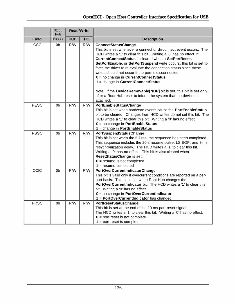
OpenHCI - Open Host Controller Interface Specification for USB
136
Root Hub
Read/Write
Field Reset HCD HC Description
CSC 0b R/W R/W ConnectStatusChange This bit is set whenever a connect or disconnect event occurs. The HCD writes a ‘1’ to clear this bit. Writing a ‘0’ has no effect. If CurrentConnectStatus is cleared when a SetPortReset, SetPortEnable, or SetPortSuspend write occurs, this bit is set to force the driver to re-evaluate the connection status since these writes should not occur if the port is disconnected. 0 = no change in CurrentConnectStatus 1 = change in CurrentConnectStatus Note: If the DeviceRemovable[NDP] bit is set, this bit is set only after a Root Hub reset to inform the system that the device is attached.
PESC 0b R/W R/W PortEnableStatusChange This bit is set when hardware events cause the PortEnableStatus bit to be cleared. Changes from HCD writes do not set this bit. The HCD writes a ‘1’ to clear this bit. Writing a ‘0’ has no effect. 0 = no change in PortEnableStatus 1 = change in PortEnableStatus
PSSC 0b R/W R/W PortSuspendStatusChange This bit is set when the full resume sequence has been completed. This sequence includes the 20-s resume pulse, LS EOP, and 3-ms resychronization delay. The HCD writes a ‘1’ to clear this bit. Writing a ‘0’ has no effect. This bit is also cleared when ResetStatusChange is set. 0 = resume is not completed 1 = resume completed
OCIC 0b R/W R/W PortOverCurrentIndicatorChange This bit is valid only if overcurrent conditions are reported on a per-port basis. This bit is set when Root Hub changes the PortOverCurrentIndicator bit. The HCD writes a ‘1’ to clear this bit. Writing a ‘0’ has no effect. 0 = no change in PortOverCurrentIndicator 1 = PortOverCurrentIndicator has changed
PRSC 0b R/W R/W PortResetStatusChange This bit is set at the end of the 10-ms port reset signal. The HCD writes a ‘1’ to clear this bit. Writing a ‘0’ has no effect. 0 = port reset is not complete 1 = port reset is complete

OpenHCI - Open Host Controller Interface Specification for USB
137
PCI CONFIGURATION
APPENDIX A
PCI INTERFACE
This section describes the configuration registers necessary for the OpenHCI-compliant USB Host Controller to interface with the other system components in a PCI-based PC host. Specifically, only the bits relevant to the implementation of a USB Host Controller with PCI interface, which complies with Release 1.0 of the OpenHCI Specification, are described here. For the definition of the other bits/registers which are not described here, please refer to the PCI Specification, Revision 2.1. In a typical PCI-based PC host, the registers described here are accessed for set-up during PCI initialization. They might also be accessed through special cycles during normal system runtime. Header type 0 is the format for the device’s configuration header region, the first 16 Dwords. They are also commonly called the PCI configuration spaces of a PCI device. For the OpenHCI-compliant USB Host Controller with PCI interface, the operational registers (i.e., PCI nonconfiguration spaces) that are described in the Operational Registers chapter are directly memory-mapped into the main memory of the PC host system. “Reset” issued to the Host Controller through its respective programming interface does not affect the contents of the PCI configuration space (contents of the operational registers of the Root Hub are also not affected). “Hardware reset” issued by the system logic in the PC host, during system power-up and “cold-boot”, causes all of the on-chip registers of the Host Controller and the Root Hub to return their default values. In the following sections, the PCI configuration spaces are described in relation to their individual logical responsibilities. As such, they are of either byte-/word-oriented. Nevertheless, the alignment for decoding purpose should adhere strictly to those defined in the PCI Specification, Revision 2.1. Note: The LATENCY_TIMER in the PCI configuration spaces defines the minimum amount of time
that the Host Controller is permitted to retain ownership of the bus after it has acquired bus ownership and has initiated a subsequent transaction. It should be set to a value that reflects the nominal burst size of the underlying device, resulting in a good compromise between the utilization and efficiency of the PCI bus. In determining the value, it should be considered that the maximum size of packet transferred over the USB ranges from 64 bytes to 1023 bytes. A value of ‘16h’ is recommended, as it will allow a total of 24 PCI clocks, sufficient for a burst transfer of 64-byte (assuming a target initial latency of 8 PCI clocks).

OpenHCI - Open Host Controller Interface Specification for USB
138
PCI Configuration Spaces for OpenHCI-compliant USB Host Controller
Table A-1 provides a summary of the registers that are necessary for the OpenHCI-compliant USB Host Controller to be successfully configured in a PCI-based PC host. Those registers which are implementation-dependent are not described in the table; their implementation is left to the individual manufacturers for innovation. However, they are defined in the PCI Specification, Revision 2.1 (PCI Special Interest Group, 1995).
Table A - 1: OpenHCI-Related PCI Configuration Registers
Offset Register Description 05-04 COMMAND Provides coarse control over a device’s ability to generate
and respond to PCI cycles 0B-09 CLASS_CODE Identifies the generic function of the device 13-10 BAR_OHCI Specifies the base address of a contiguous block in the main
memory of the PC host, from which 4 KB of directly-mapped addressing spaces are reserved by OpenHCI for the operational registers of the Host Controller
OpenHCI
OperationalRegistersMode
Host ControllerCommunications Area
HCCAStatusEventFrame Int
Control
Interrupt 0Interrupt 1
Interrupt 31. . .
Interrupt 2
Done
. . .
. . .
Bulk
Ratio
Shared RAMDevice Registerin memory space
PCI Device
CLASS_CODE
. . .
BAR_OHCI
. . .
. . .
. . .
COMMAND
Figure A - 1: The PCI Configuration Spaces for OpenHCI
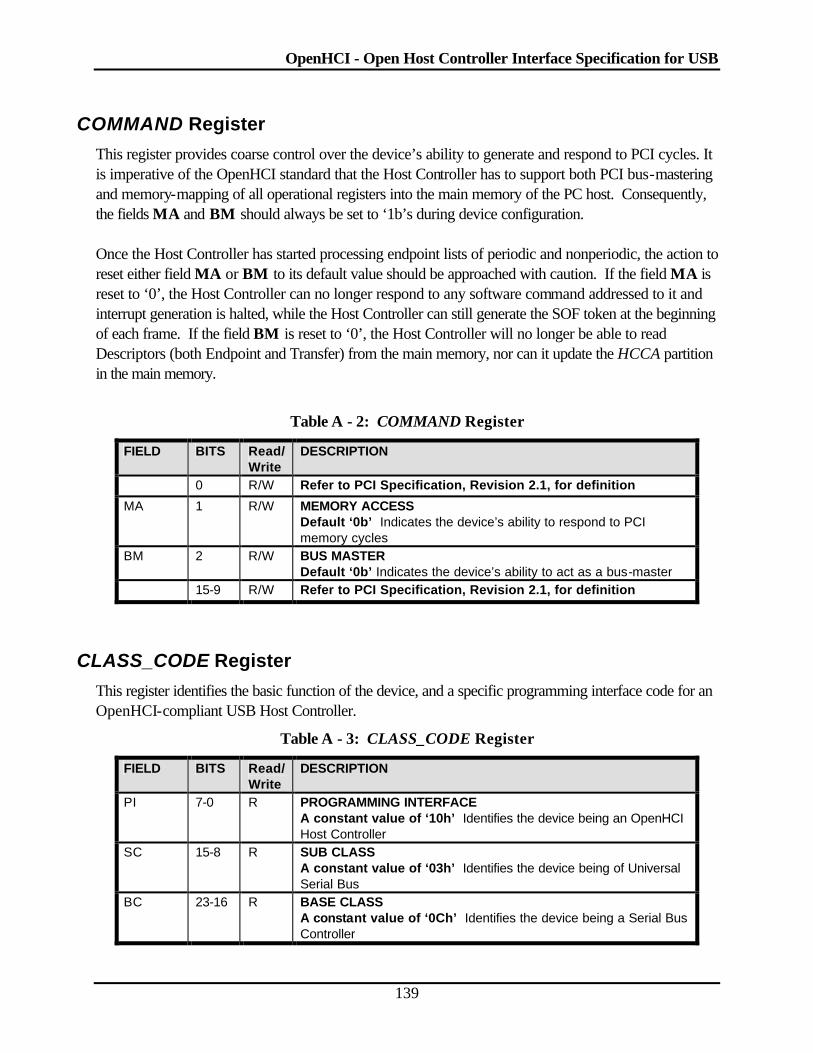
OpenHCI - Open Host Controller Interface Specification for USB
139
COMMAND Register
This register provides coarse control over the device’s ability to generate and respond to PCI cycles. It is imperative of the OpenHCI standard that the Host Controller has to support both PCI bus-mastering and memory-mapping of all operational registers into the main memory of the PC host. Consequently, the fields MA and BM should always be set to ‘1b’s during device configuration. Once the Host Controller has started processing endpoint lists of periodic and nonperiodic, the action to reset either field MA or BM to its default value should be approached with caution. If the field MA is reset to ‘0’, the Host Controller can no longer respond to any software command addressed to it and interrupt generation is halted, while the Host Controller can still generate the SOF token at the beginning of each frame. If the field BM is reset to ‘0’, the Host Controller will no longer be able to read Descriptors (both Endpoint and Transfer) from the main memory, nor can it update the HCCA partition in the main memory.
Table A - 2: COMMAND Register
FIELD BITS Read/Write
DESCRIPTION
0 R/W Refer to PCI Specification, Revision 2.1, for definition
MA 1 R/W MEMORY ACCESS Default ‘0b’ Indicates the device’s ability to respond to PCI memory cycles
BM 2 R/W BUS MASTER Default ‘0b’ Indicates the device’s ability to act as a bus-master
15-9 R/W Refer to PCI Specification, Revision 2.1, for definition
CLASS_CODE Register
This register identifies the basic function of the device, and a specific programming interface code for an OpenHCI-compliant USB Host Controller.
Table A - 3: CLASS_CODE Register
FIELD BITS Read/Write
DESCRIPTION
PI 7-0 R PROGRAMMING INTERFACE A constant value of ‘10h’ Identifies the device being an OpenHCI Host Controller
SC 15-8 R SUB CLASS A constant value of ‘03h’ Identifies the device being of Universal Serial Bus
BC 23-16 R BASE CLASS A constant value of ‘0Ch’ Identifies the device being a Serial Bus Controller
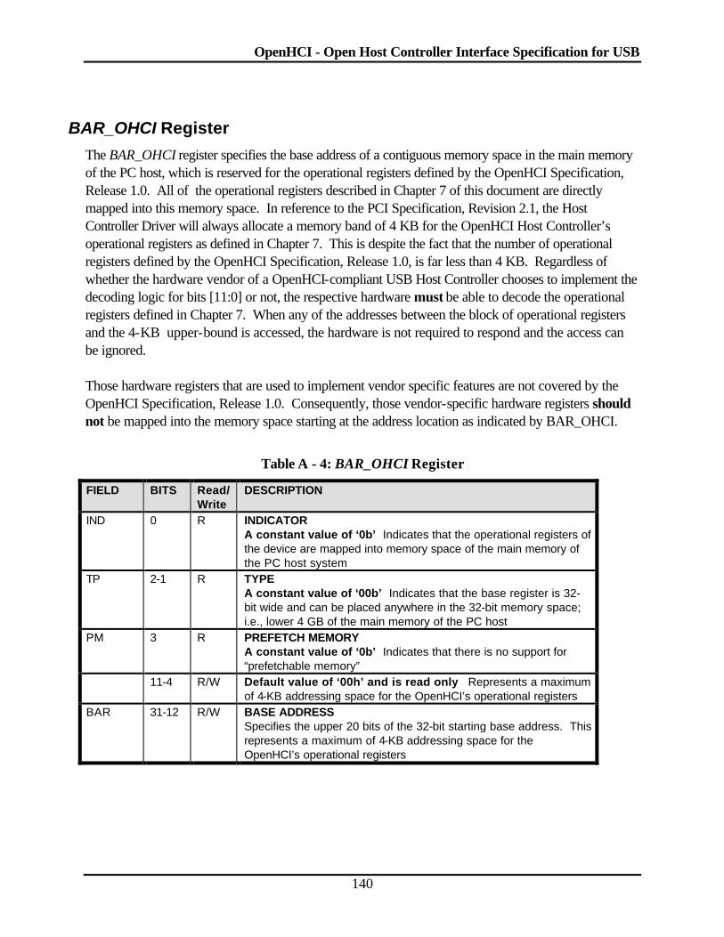
OpenHCI - Open Host Controller Interface Specification for USB
140
BAR_OHCI Register
The BAR_OHCI register specifies the base address of a contiguous memory space in the main memory of the PC host, which is reserved for the operational registers defined by the OpenHCI Specification, Release 1.0. All of the operational registers described in Chapter 7 of this document are directly mapped into this memory space. In reference to the PCI Specification, Revision 2.1, the Host Controller Driver will always allocate a memory band of 4 KB for the OpenHCI Host Controller’s operational registers as defined in Chapter 7. This is despite the fact that the number of operational registers defined by the OpenHCI Specification, Release 1.0, is far less than 4 KB. Regardless of whether the hardware vendor of a OpenHCI-compliant USB Host Controller chooses to implement the decoding logic for bits [11:0] or not, the respective hardware must be able to decode the operational registers defined in Chapter 7. When any of the addresses between the block of operational registers and the 4-KB upper-bound is accessed, the hardware is not required to respond and the access can be ignored. Those hardware registers that are used to implement vendor specific features are not covered by the OpenHCI Specification, Release 1.0. Consequently, those vendor-specific hardware registers should not be mapped into the memory space starting at the address location as indicated by BAR_OHCI.
Table A - 4: BAR_OHCI Register
FIELD BITS Read/Write
DESCRIPTION
IND 0 R INDICATOR A constant value of ‘0b’ Indicates that the operational registers of the device are mapped into memory space of the main memory of the PC host system
TP 2-1 R TYPE A constant value of ‘00b’ Indicates that the base register is 32-bit wide and can be placed anywhere in the 32-bit memory space; i.e., lower 4 GB of the main memory of the PC host
PM 3 R PREFETCH MEMORY A constant value of ‘0b’ Indicates that there is no support for “prefetchable memory”
11-4 R/W Default value of ‘00h’ and is read only Represents a maximum of 4-KB addressing space for the OpenHCI’s operational registers
BAR 31-12 R/W BASE ADDRESS Specifies the upper 20 bits of the 32-bit starting base address. This represents a maximum of 4-KB addressing space for the OpenHCI’s operational registers

OpenHCI - Open Host Controller Interface Specification for USB
141
OVERVIEW To support applications and drivers in non-USB-aware environments (e.g., DOS), the Host Controller needs to provide some amount of hardware support for the emulation of a PS/2 keyboard and/or mouse by their USB equivalents. For Open HCI, this emulation support is provided by a set of registers that are controlled by code running in SMM. Working in conjunction, this hardware and software produces approximately the same behavior-to-application code as would be produced by a PS/2-compatible keyboard and/or mouse interface. To minimize hardware impact, the Host Controller accesses a USB keyboard and/or mouse using the standard OpenHCI descriptor-based accesses. The emulation code sets up the appropriate Endpoint Descriptors and Transfer Descriptors that cause data to be sent to or received from a USB keyboard/mouse using the normal USB protocols. When data is received from the keyboard/mouse, the emulation code is notified and becomes responsible for translating the USB keyboard/mouse data into a data sequence that is equivalent to what would be produced by a PS/2-compatible keyboard/mouse interface. The translated data is made available to the system through the legacy keyboard interface I/O addresses at 60h and 64h. Likewise, when data/control is to be sent to the keyboard (as indicated by the system writing to the legacy keyboard interface), the emulation code is notified and becomes responsible for translating the information into appropriate data to be sent to the USB keyboard/mouse through the transfer descriptor mechanism. On the PS/2 keyboard/mouse interface, a read of I/O port 60h returns the current contents of the keyboard output buffer; a read of I’O port 64h returns the contents of the keyboard status register. An I/O write to port 60h or 64h puts data into the keyboard input buffer (data is being input into the keyboard subsystem). When emulation is enabled, reads and writes of registers 60h and 64h are captured in HceOutput, HceStatus, and/or HceInput operational registers. The emulation hardware described in this document supports a mixed environment in which either the keyboard or mouse is located on USB and the other device is attached to a standard PS/2 interface.
APPENDIX B
LEGACY SUPPORT INTERFACE SPECIFICATION

OpenHCI - Open Host Controller Interface Specification for USB
142
OPERATIONAL THEORY Keyboard/Mouse Input
The Interrupt Transfer Descriptor for the USB keyboard and/or mouse is processed at the rate established by the Endpoint Descriptor’s location(s) in the interrupt list (a 1-ms rate is the recommended rate for emulation). The Transfer Descriptors are processed as normal by the Host Controller. When a successful transfer of data has occurred from the keyboard, the Transfer Descriptor is moved to the Done Queue by the Host Controller. At the beginning of the next frame when the interrupt associated with the transfer completion is to be signaled, an interrupt is generated. System software should ensure that the InterruptRouting bit in HcControl is set to 1 so that these interrupts will result in an SMI. Upon receipt of the SMI, the emulation software removes the Transfer Descriptor from the Done Queue, clears the HC IRQ, and translates the keyboard/mouse data into a equivalent PS/2-compatible sequence for presentation to the application software. For each byte of PS/2-compatible data that is to be presented to the applications software, the emulation code writes to the HceOutput register. The emulation code then sets the appropriate bits in the HceStatus register (normally, OutputFull is set for keyboard data and OutputFull plus AuxOutputFull for mouse data). If keyboard/mouse interrupts are enabled, setting the HceStatus register bits cause the generation of an IRQ1 for keyboard data and IRQ12 for mouse data. The emulation code then exits and waits for the next emulation interrupt. When the host CPU exits from SMM, it can service the pending IRQ1/IRQ12. This normally results in a read from I/O port 60h. When I/O port 60h is read, the Host Controller intercepts the access and returns the current contents of HceOutput. The Host Controller then also clears the OutputFull bit in HceStatus and de-asserts IRQ1/IRQ12. If the emulation software has multiple characters to send to the application software, it sets the CharacterPending bit in the HceControl register. This causes the Host Controller to generate an emulation interrupt on the next frame boundary after the application has read from port 60h (HceOutput.)

OpenHCI - Open Host Controller Interface Specification for USB
143
Keyboard Output Keyboard output is indicated by application software writing data to either I/O address 60h or 64h. Upon a write to either address, the Host Controller captures the data in the HceInput register and, except in the case of a Gate A20 sequence, updates the HceStatus register’s InputFull and CmdData bits. When the InputFull bit is set, an emulation interrupt is generated. Upon receipt of the emulation interrupt, the emulation software reads HceControl and HceStatus to determine the cause of the emulation interrupt and performs the operation indicated by the data.
Emulation Interrupts Emulation interrupts are caused by reads and writes of the emulation registers. Emulation software can also receive interrupts due to Host Controller events as defined in the OpenHCI base specification. However, as used in this document, these are not emulation interrupts. Interrupts generated by the emulation hardware are steered by the Host Controller to either an SMI or the standard Host Controller Interrupt. Steering is determined by the setting of the InterruptRouting bit in the HcControl Register. Emulation interrupts for data coming from the keyboard/mouse are generated on frame boundaries. At the beginning of each frame, the conditions which define asynchronous emulation interrupt are checked and, if an interrupt condition exists, the emulation interrupt is signaled to the host at the same time the interrupts are coming from the Host Controller’s normal USB processing. This has the effect of reducing the number of SMIs that are generated for legacy input to no more than 1,000 per second. Although still somewhat large, this number of interrupts is less than the number that could be generated if emulation interrupts were not merged with the normal Host Controller interrupts. The number of emulation interrupts is limited because the maximum rate of data delivery to an application cannot be more than 1,000 bytes (key strokes) per second. A benefit of this rule is that, for normal keyboard and mouse operations, only one SMI is required for each data byte sent to the application. Additionally, delay of the interrupt until the next Start of Frame causes data persistence for keyboard input data that is equivalent to that provided by an 8042.

OpenHCI - Open Host Controller Interface Specification for USB
144
Mixed Environment A mixed environment is one in which a USB device and a PS/2 device are supported simultaneously (e.g., a USB keyboard and a PS/2 mouse). The mixed environment is supported by allowing the emulation software to control the PS/2 interface. Control of this interface includes capturing I/O accesses to port 60h and 64h and also includes capture of interrupts from the PS/2 keyboard controller. IRQ1 and IRQ12 from the legacy keyboard controller are routed through the Host Controller. When ExternalIRQEn in HceControl is set, IRQ1 and IRQ12 from the legacy keyboard controller are blocked at the Host Controller and an emulation interrupt is generated instead. This allows the emulation software to capture data coming from the legacy controller and presents it to the application through the emulated interface.
Gate A20 Sequence The Gate A20 sequence occurs frequently in DOS applications. Mostly, the sequence is to enable A20. To reduce the number of SMIs caused by the Gate A20 sequence, the host controller generates an SMI only if the A20 sequence would change the state of Gate A20. The Gate A20 sequence is initiated with a write of D1h to port 64h. On detecting this write, the HC sets the GateA20Sequence bit in HceControl. It captures the data byte in HceInput but does not set InputFull bit in HceStatus. When GateA20Sequence is set, a write of a value to I/O port 60h that has bit 1 set to a value different than A20State in HceControl causes InputFull to be set and causes an interrupt. An SMI with both InputFull and GateA20Sequence set indicates that the application is trying to change the setting of Gate A20 on the keyboard controller. However, when GateA20Sequence is set and a write of a value to I/O port 60h that has bit 1 set to the same value as A20State in HceControl is detected, then no interrupt can occur. As mentioned above, a write to 64h of any value other than D1h causes GateA20Sequence to be cleared. If GateA20Sequence is active and a value of FFh is written to port 64h, GateA20Sequence is cleared but InputFull is not set. A write of any value other than D1h or FFh causes InputFull to be set which then causes an SMI. A write of FFh to port 64h when GateA20Sequence is not set causes InputFull to be set.

OpenHCI - Open Host Controller Interface Specification for USB
145
SYSTEM REQUIREMENTS The sections below define the system requirements that must be met in order for the OpenHCI legacy support to function properly.
Host Controller Mapping The Host Controller uses memory addresses to enable system software to access its operational registers. In a PCI implementation, the address of the Host Controller operations registers is set in BAR_OHCI. The address range specified in BAR_OHCI must be accessible to SMM code. The address in BAR_OHCI should not be modified by any software while the emulation software has control of the Host Controller. The only exception to this is when the OS is booting and is trying to interrogate the PCI bus. It is common for an OS, as it is loaded, to enumerate and ‘size’ the various buses on the machine. For a PCI system, the OS typically writes a value to each card’s BAR to determine the memory space occupied by that card. If emulation is running during enumeration, the Host Controller may generate an SMI as the OS is changing the BAR from the value that the emulation code is using. To prevent problems during enumeration and ‘sizing’ of the PCI bus, a specific OS sequence is defined for ‘sizing’ the Host Controller on PCI systems: Save the current value of the PCI COMMAND register Save the current value of BAR_OHCI Clear the Memory Access* bit in the PCI COMMAND register. Write 0xFFFFFFFF to BAR_OHCI Read BAR_OHCI to determine the block size Restore the original version of BAR_OHCI Restore the PCI COMMAND register (*The Memory Access is bit 1 of the PCI COMMAND register. This field has several aliases in various documents but is labeled Memory Access in Appendix A of the OpenHCI Host Controller Specification.) The SMM code that services SMI should check that the Memory Access bit on the Host Controller is set before accessing the Host Controller operational registers. The HC should not generate an emulation interrupt while the Memory Access bit not set to 1. If an interrupt is being signaled when Memory Access is set to 0, the Host Controller inactivates that interrupt (including SMI). If an interrupt condition exists when Memory Access is set to 1, that interrupt is immediately signaled. If ExternalIRQEn in HceControl is not set, IRQ1 and IRQ12 are propagated through the Host Controller regardless of the setting of Memory Access.

OpenHCI - Open Host Controller Interface Specification for USB
146
SMI Signaling The OpenHCI controller must be able to signal an SMI event to the x86 system processor. Since none of the standard add-in card interfaces make provision for SMI signaling, it is assumed that this requirement implies that the OpenHCI controller is located on the system motherboard.
Intercept Port 60h and 64h Accesses When emulation is enabled, I/O accesses of I/O ports 60h and 64h must be handled by the Host Controller. The Host Controller must be positioned in the system so that it can do a positive decode of accesses to I/O addresses 60h and 64h on the PCI bus. If a keyboard controller is present in the system, it must either use subtractive decode or have provisions to disable its decode of ports 60h and 64h. If the legacy keyboard controller uses positive decode and is turned off during emulation, it must be possible for the emulation code to quickly re-enable and disable the legacy keyboard controller’s 60h and 64h decode. This is necessary to support a mixed operating environment.
Interrupts The Host Controller must connect to IRQ1 and IRQ12 on the system board and be wired OR with other non-legacy IRQ1 and IRQ12 sources. IRQ1 and IRQ12 from the legacy keyboard controller (if present) must be routed through the Host Controller.
Run-time Memory Legacy emulation requires that the Host Controller have read/write access to a portion of system memory that is not used by a system OS for any purpose. In addition, this memory must be accessible by the host CPU while the host CPU is in SMM.

OpenHCI - Open Host Controller Interface Specification for USB
147
PROGRAMMING INTERFACE Modifications to existing registers
HcRevision Register
The following modification is needed to the HcRevision Register:
3 0 0 0 1 8 7 0
reserved L REV
Figure B-1: HcRevision Register
Table B-1: HcRevision Register Fields
Read/Write
Key Reset HCD HC Description
REV 10h R R Revision This read-only field contains the BCD representation of the version of the HCI specification that is implemented by this HC. For example, a value of 11h corresponds to version 1.1. All of the HC implementations that are compliant with this specification will have a value of 10h.
L 1b R R Legacy This read-only field is 1 to indicate that the legacy support registers are present in this HC.
Legacy Support Registers Four operational registers are used to provide the legacy support . Each of these registers is located on a 32-bit boundary. The offset of these registers is relative to the base address of the Host Controller operational registers with HceControl located at offset 100h.
Table B-2: Legacy Support Registers
Offset Register Description 100h HceControl Used to enable and control the emulation hardware and report
various status information. 104h HceInput Emulation side of the legacy Input Buffer register. 108h HceOutput Emulation side of the legacy Output Buffer register where keyboard
and mouse data is to be written by software. 10Ch HceStatus Emulation side of the legacy Status register.

OpenHCI - Open Host Controller Interface Specification for USB
148
Three of the operational registers (HceStatus, HceInput, HceOutput) are accessible at I/O address 60h and 64h when emulation is enabled. Reads and writes to the registers using I/O addresses have side effects as outlined in the Table B-3.
Table B-3: Emulated Registers
I/O Address
Cycle Type
Register Contents Accessed/Modified
Side Effects
60h IN HceOutput IN from port 60h will set OutputFull in HceStatus to 0
60h OUT HceInput OUT to port 60h will set InputFull to 1 and CmdData to 0 in HceStatus.
64h IN HceStatus IN from port 64h returns current value of HceStatus with no other side effect.
64h OUT HceInput OUT to port 64h will set InputFull to 0 and CmdData in HceStatus to 1.
HceInput Register
Table B-4: HceInput Registers
bit Field R/W Description 7-0 InputData R/W This register holds data that is written to I/O ports 60h and 64h.
8-31 Reserved -
I/O data that is written to ports 60h and 64h is captured in this register when emulation is enabled. This register may be read or written directly by accessing it with its memory address in the Host Controller’s operational register space. When accessed directly with a memory cycle, reads and writes of this register have no side effects.
HceOutput Register
Table B-5: HceOutput Registers
bit Field R/W Description 7-0 OutputData R/W This register hosts data that is returned when an I/O read of port
60h is performed by application software. 8-31 Reserved -
The data placed in this register by the emulation software is returned when I/O port 60h is read and emulation is enabled. On a read of this location, the OutputFull bit in HceStatus is set to 0.

OpenHCI - Open Host Controller Interface Specification for USB
149
HceStatus Register
Table B-6: HceStatus Register
bit Field R/W Description 0 OutputFull R/W The HC sets this bit to 0 on a read of I/O port 60h. If IRQEn is set
and AuxOutputFull is set to 0, then an IRQ1 is generated as long as this bit is set to 1. If IRQEn is set and AuxOutputFull is set to 1, then an IRQ12 is generated as long as this bit is set to 1. While this bit is 0 and CharacterPending in HceControl is set to 1, an emulation interrupt condition exists.
1 InputFull R/W Except for the case of a Gate A20 sequence, this bit is set to 1 on an I/O write to address 60h or 64h. While this bit is set to 1 and emulation is enabled, an emulation interrupt condition exists.
2 Flag R/W Nominally used as a system flag by software to indicate a warm or cold boot.
3 CmdData R/W The HC sets this bit to 0 on an I/O write to port 60h and to 1 on an I/O write to port 64h.
4 Inhibit Switch R/W This bit reflects the state of the keyboard inhibit switch and is set if the keyboard is NOT inhibited.
5 AuxOutputFull R/W IRQ12 is asserted whenever this bit is set to 1 and OutputFull is set to 1 and the IRQEn bit is set.
6 Time-out R/W Used to indicate a time-out 7 Parity R/W Indicates parity error on keyboard/mouse data.
8-31 Reserved -
The contents of the HceStatus Register are returned on an I/O Read of port 64h when emulation is enabled. Reads and writes of port 60h and writes to port 64h can cause changes in this register. Emulation software can directly access this register through its memory address in the Host Controller’s operational register space. Accessing this register through its memory address produces no side effects.

OpenHCI - Open Host Controller Interface Specification for USB
150
HceControl Register
Table B-7: HceControl Register
bit Field Reset R/W Description 0 EmulationEnable 0b R/W When set to 1, the HC is enabled for legacy emulation. The
HC decodes accesses to I/O registers 60h and 64h and generates IRQ1 and/or IRQ12 when appropriate. Additionally, the HC generate s an emulation interrupt at appropriate times to invoke the emulation software.
1 EmulationInterrupt - R This bit is a static decode of the emulation interrupt condition.
2 CharacterPending 0b R/W When set, an emulation interrupt is generated when the OutputFull bit of the HceStatus register is set to 0.
3 IRQEn 0b R/W When set, the HC generates IRQ1 or IRQ12 as long as the OutputFull bit in HceStatus is set to 1. If the AuxOutputFull bit of HceStatus is 0, then IRQ1 is generated; if it is 1, then an IRQ12 is generated.
4 ExternalIRQEn 0b R/W When set to 1, IRQ1 and IRQ12 from the keyboard controller causes an emulation interrupt. The function controlled by this bit is independent of the setting of the EmulationEnable bit in this register.
5 GateA20Sequence 0b R/W Set by HC when a data value of D1h is written to I/O port 64h. Cleared by HC on write to I/O port 64h of any value other than D1h.
6 IRQ1Active 0b R/W Indicates that a positive transition on IRQ1 from keyboard controller has occurred. SW may write a 1 to this bit to clear it (set it to 0). SW write of a 0 to this bit has no effect.
7 IRQ12Active 0b R/W Indicates that a positive transition on IRQ12 from keyboard controller has occurred. SW may write a 1 to this bit to clear it (set it to 0). SW write of a 0 to this bit has no effect.
8 A20State 0b R/W Indicates current state of Gate A20 on keyboard controller. Used to compare against value written to 60h when GateA20Sequence is active.
9-31 Reserved - - Must read as 0s.

OpenHCI - Open Host Controller Interface Specification for USB
151
IMPLEMENTATION NOTES Emulation Interrupt Decode
Emulation interrupts are of two types: frame synchronous and asynchronous. For frame synchronous interrupts, the conditions for a frame synchronous interrupt are sampled by the Host Controller at each USB frame interval and, if an interrupt condition exists, it is signaled at that time. For asynchronous interrupts, the interrupt is signaled as soon as the condition exists. The equation for the synchronous emulation interrupt condition is:
synchronousInterrupt = HceControl.EmulationEnable AND HceControl.CharacterPending AND NOT(HceStatus.OutputFull)
When this decode is true, an emulation interrupt is generated at the start of the next USB frame. The interrupt condition is latched until the decode becomes false. The equation for the asynchronous interrupt condition is:
asynchronousInterrupt = (HceControl.EmulationEnable AND HceStatus.InputFull) OR (HceControl.ExternIRQEn AND (HceControl.IRQ1Active OR HceControl.IRQ12Active))
A20 Gate The A20State bit in the host controller should be brought to a pin on the Host Controller, through suitable buffering, for inclusion in the Gate A20 logic on the motherboard.