jb4 n54 g5 2-step relay/no-lift shifting install guide · jb4_n54 g5 2-step relay/no-lift shifting...
TRANSCRIPT
JB4_N54 G5 2-Step Relay/No-Lift Shifting Install Guide
Revised 8/20/2014
Use subject to terms and conditions posted at
http://www.burgertuning.com/terms.html
THIS PART IS LEGAL FOR USE ONLY IN COMPETITION RACING VEHICLES AS DEFINED UNDER CALIFORNIA
LAW, AND IS NOT LEGAL FOR USE IN ANY OTHER MOTOR VEHICLE. California law defines a "racing
vehicle" as "a competition vehicle not used on public highways." (Calif. Health & Safety Code 39048) This
part may only be used on competition racing vehicles operated exclusively on a closed course in
conjunction with a sanctioned racing event. Competition-only motor vehicles may not be driven to a
racing event on a public highway and must be transported on a trailer or other carrier. USE OF THIS
PART IN ANY OTHER VEHICLE MAY SUBJECT YOU TO FINES AND PENALTIES FOR VIOLATION OF FEDERAL
AND/OR STATE LAW, WILL VOID YOUR WARRANTY
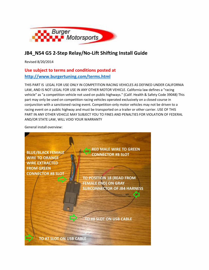
General install overview:

Please refer to the N54_JB4’s install guide for more information on accessing the ECU area to install this
part: http://burgertuning.com/instructions/JB4PnP.pdf
1. Remove the gray casing from the BMS USB cable
There are several small screws, so take care not to lose them. Once the casing is removed, the USB
cable’s DB9 housing will be exposed.
Note the positions marked on the exposed DB9 housing. These will be used to put the wires into the
correct positions in the next step.
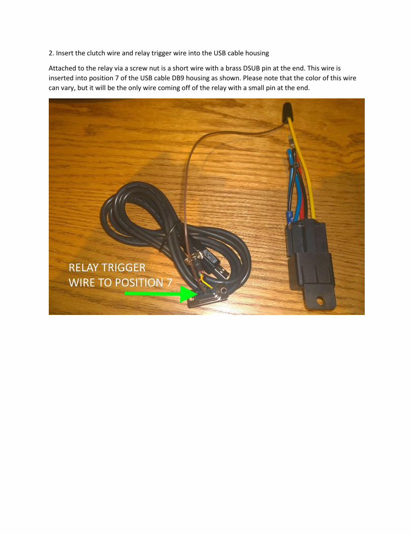
2. Insert the clutch wire and relay trigger wire into the USB cable housing
Attached to the relay via a screw nut is a short wire with a brass DSUB pin at the end. This wire is
inserted into position 7 of the USB cable DB9 housing as shown. Please note that the color of this wire
can vary, but it will be the only wire coming off of the relay with a small pin at the end.

The brass DSUB pin end of the loose clutch wire is installed into position 8 of the USB cable DB9 housing.
Please note that the color of the clutch wire can vary, but it will be the loose Y-shaped wire with a male
and female pin at one end and a brass DSUB pin at the other.
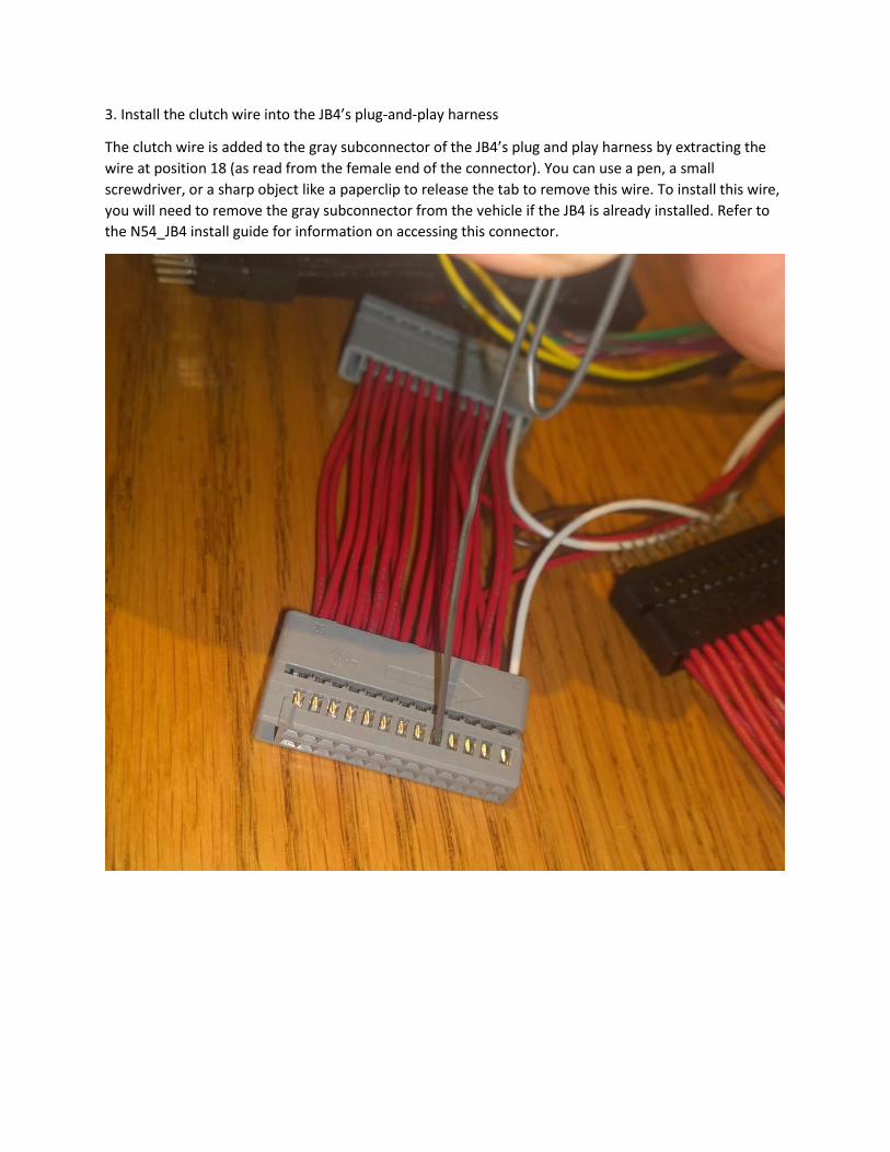
3. Install the clutch wire into the JB4’s plug-and-play harness
The clutch wire is added to the gray subconnector of the JB4’s plug and play harness by extracting the
wire at position 18 (as read from the female end of the connector). You can use a pen, a small
screwdriver, or a sharp object like a paperclip to release the tab to remove this wire. To install this wire,
you will need to remove the gray subconnector from the vehicle if the JB4 is already installed. Refer to
the N54_JB4 install guide for information on accessing this connector.
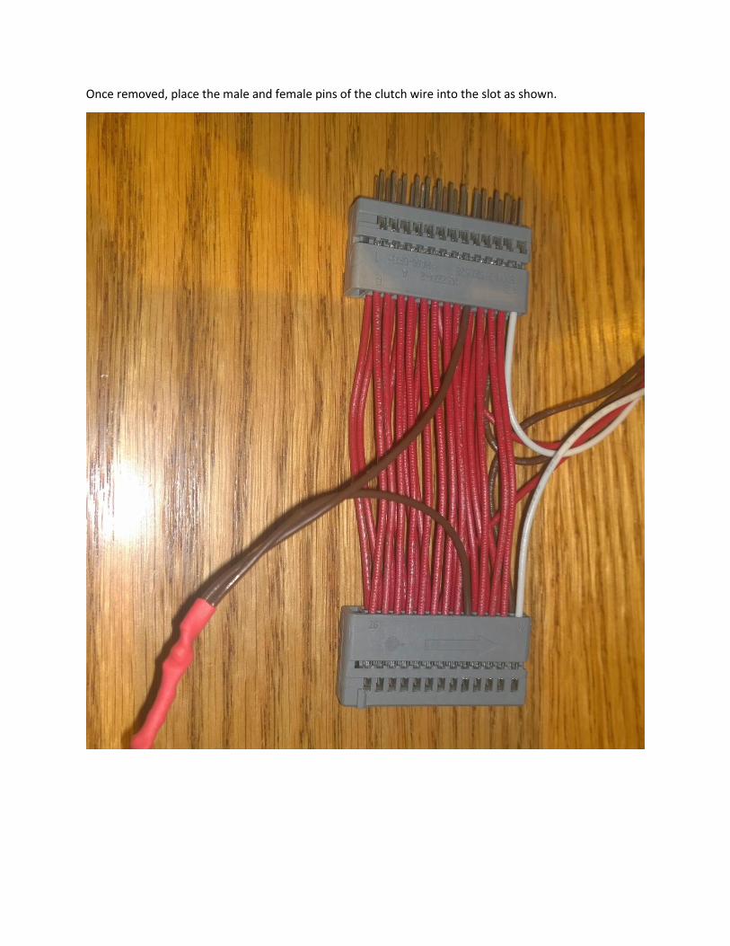
Once removed, place the male and female pins of the clutch wire into the slot as shown.
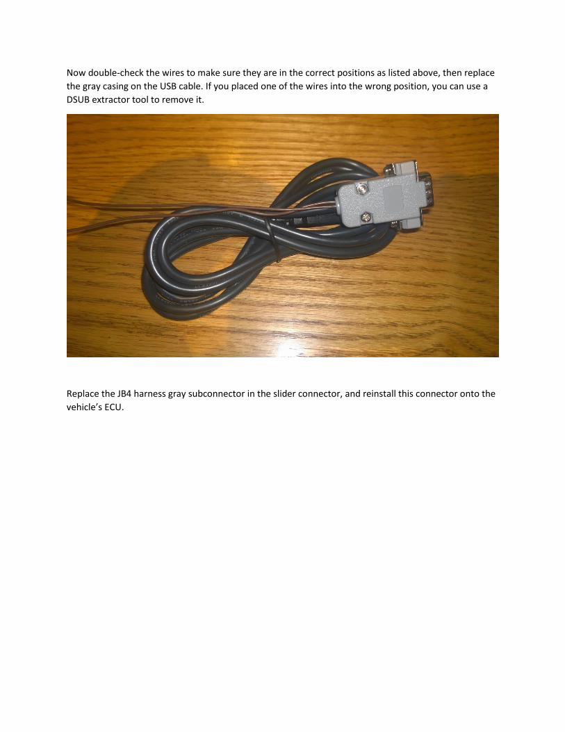
Now double-check the wires to make sure they are in the correct positions as listed above, then replace
the gray casing on the USB cable. If you placed one of the wires into the wrong position, you can use a
DSUB extractor tool to remove it.
Replace the JB4 harness gray subconnector in the slider connector, and reinstall this connector onto the
vehicle’s ECU.
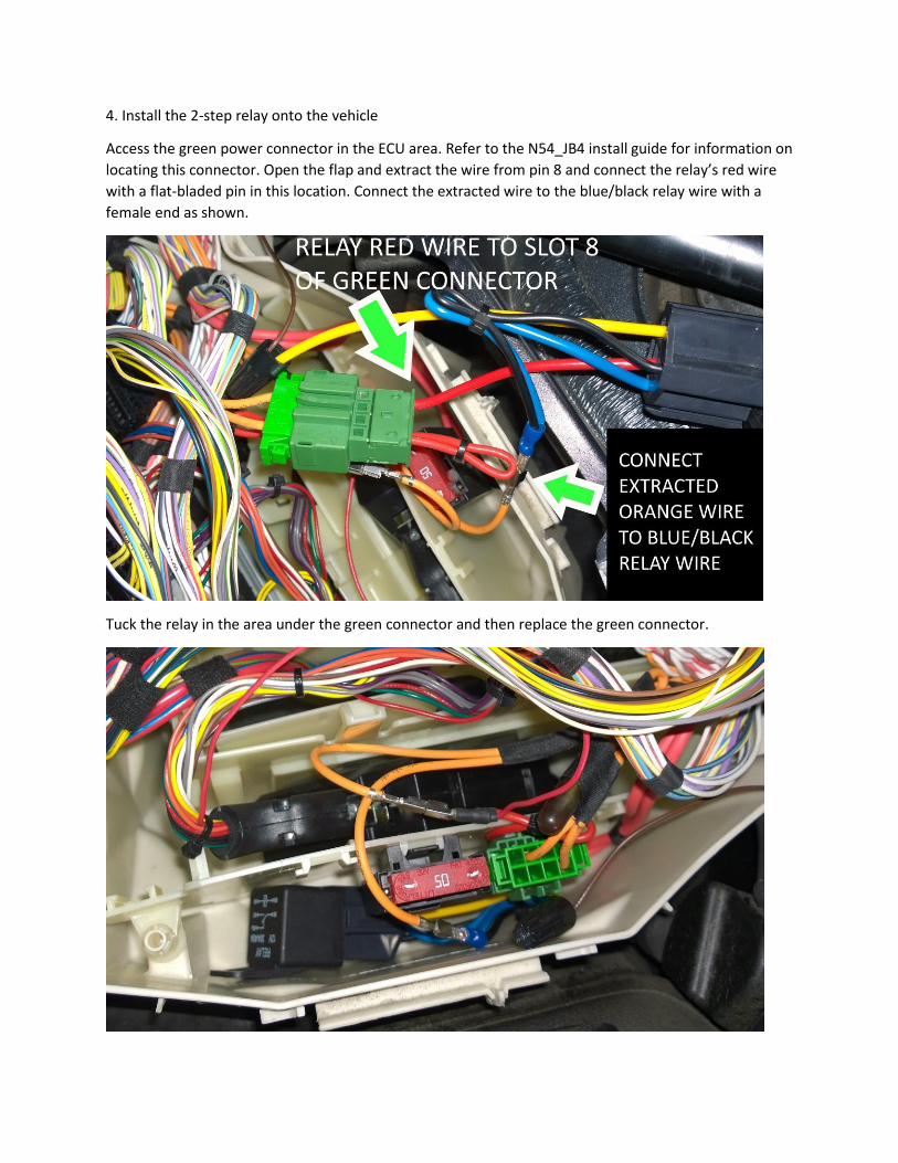
4. Install the 2-step relay onto the vehicle
Access the green power connector in the ECU area. Refer to the N54_JB4 install guide for information on
locating this connector. Open the flap and extract the wire from pin 8 and connect the relay’s red wire
with a flat-bladed pin in this location. Connect the extracted wire to the blue/black relay wire with a
female end as shown.
Tuck the relay in the area under the green connector and then replace the green connector.
5. Finishing up
Reconnect the USB cable to the JB4 control box. To enable No-Lift Shifting, set menu 8 in dash to 2000
RPM or higher.
NLS will cut engine power above the 2-step RPM set point when pressing the clutch while the gas is fully
pressed. The pedal must be at 100% for the 2-step or NLS functions to work.
Practice doing full throttle runs at lower RPM to get the hang of it. When you press the clutch in while
the gas is 100% down the RPM should drop like a rock, and bounce around the 2-step RPM set point for
as long as you keep the clutch depressed.
6. Troubleshooting
Note if the car cranks without starting after installing the relay something is likely wired wrong. Please
double-check each of the wiring connections.
If you are unable to get the relay to trigger with the throttle pedal fully pressed, take a short datalog of a
full throttle run to verify that your pedal signal is going to 100%. If there are any obstructions, and the
throttle is not reaching 100%, the relay will not work.
If you have verified that the pedal signal is going to 100% and the relay is still not working with the
clutch depressed, please set Future Use D on the User Adjustment tab to 14 and save the setting. While
connected, the low fuel pressure setting should switch between 0 and 1 as you press and let off the
clutch.
If both the throttle pedal and clutch wire readings are fine, and the relay still does not work, you can
verify the function of the relay with this test. With the vehicle idling, remove the wire nut from the 2-
step relay’s trigger wire, and touch the twisted wire pair to ground. The vehicle should start to stall. If it
does not, something is probably wired wrong. Please double-check the positions of the wires in the USB
cable housing and the power connections to make sure they are in the correct slots.
If all else fails, please send detailed photos of your install to [email protected]