jb n55 stage 1 and stage 2 install guide - vivid racing maf sensor is the easiest to reach right on...
TRANSCRIPT

JB N55 Stage 1 and Stage 2 Install Guide Last Updated: 3/18/2013
Not legal for use on emissions controlled vehicles
Use subject to terms and conditions posted at: www.burgertuning.com/terms
All Models: Before starting any electrical work always disconnect the negative
battery terminal in the trunk. Failure to do so may result in ECU damage.
Never disconnect the piggyback box, harness, or any wires while the battery is
connected. Before starting scroll through the install guide and review the
appropriate directions for your.
Once you reconnect the battery Xdrive (all wheel drive) models will have an
AWD/DSC warning that will clear itself as soon as you drive around the block.
All models will need to reset their clock. With BMWs it often takes several
attempts of saving the new time in the clock setup before it holds.

135 and E9X 335: 1) Remove the HVAC air filter and cowl. Refer to the N54 Stage 3 guide/video for detailed directions and photos. 2) Remove the yellow ECU cover. This is where the Stage1 control unit will be placed at the conclusion of the harness install. 3) Lay the harness along the top of the motor next to the existing harness with the Stage1 DB25 connector located in the ECU box. Tuck it under the strut tower brace when routing. 4) The harness consists of 4 plugs each of which intercept a particular sensor. The spacing is such that it is not possible to connect them in the wrong positions, but it may be possible to plug a connector in backwards, so take care of the orientation and ensure the tab on each connector is locking properly. 5) Identify and plug in to each sensor as shown.

The first is the TMAP sensor. It can be useful to use the flat side of a USB cable to unlock the TMAP and MAP sensors. Just slide the USB in to unlock the tab and tug the plug out. Alternatively a penny or small screwdriver will also do the trick. Once unplugged insert the Stage1 TMAP plug and plug the original in to the Stage1 female plug as shown.

The MAP sensor is positioned partly under a plastic cover which can be lifted up with your hand as shown. Install is the same as the TMAP sensor.

The MAF sensor is the easiest to reach right on top of the engine. Note the orientation as shown in the photo as this connector can easily be plugged in backwards.

The boost solenoid is located on the passenger side of the engine and can be tricky to reach. It also gets very hot so either wear a glove or wait for your motor to cool down. You release the OEM connector by pushing in on the metal release clip and lifting the plug up. Similarly you push the metal release clip in when inserting the Stage1 connector. Plug the original in to the corresponding Stage 1 connector.

Finally connect the Stage 1 control box as shown and tighten the two screws hand tight with a small screwdriver. If you have opted for the optional USB cable for future software updates you can connect that to the small DB9 connector on the back of the Stage 1 at this time. Alternatively you can leave that connector unplugged if you do not have the optional USB cable. Slide the control box in to the yellow ECU area and reinstall the yellow ECU cover. Route the harness bundle between the rubber grommet and the yellow ECU cover under one of the two indented areas. For Stage 1 the additional wires bundled next to the Stage1 control box are not used and should be left bundled. For Stage 2 refer to the additional directions at the bottom of this file for connecting the power, ground, and CAN communication wires. If you installed the optional USB cable you can route that between the smaller rubber grommet and the yellow ECU cover on the opposite side. Before reinstalling the cowl start the car. If you receive a CEL (check engine light, picture of a yellow engine inside the dash) double check each connection. If you’re unable to see any problems take photos of the install and email to [email protected] for troubleshooting support. Assuming the car starts and idles without a CEL reinstall the cowl/HVAC cover and installation is complete. Both Stage1 and Stage2 come preset so no additional software changes are required. Just drive and enjoy!

RHD 135 / 335 Stage 1
Directions are the same as above only instead of locating the Stage1 control box in the DME you will place it next to the passenger side brake booster as shown.

X1 Stage 1:
ONLY connectors #1 and #2 are used. DO NOT connect solenoid & MAF connectors. Just tuck them out of the way.
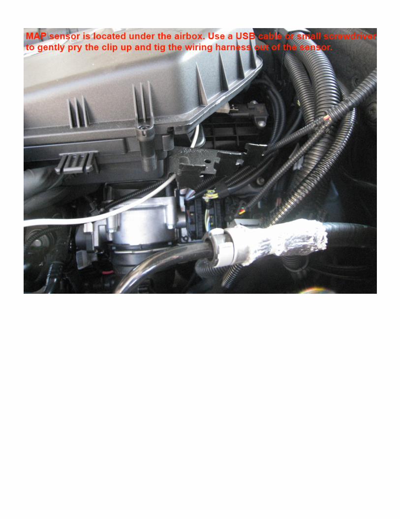
535 F10, X3, F30, and X5 Stage 1 models:
Installation is the same as above with the following differences: 1) You do not need to remove the cowl/HVAC assembly. 2) To access the MAP sensor, connector #2, you must loosen and pull up the airbox assembly a few inches. Remove the rubber grommets holding wire bundles, loose the worm clamp, and physically pull the airbox up off its rubber mounts high enough to reach the sensor below. 3) The Stage1 control box will be located under a plastic cover on the passenger side as shown. 4) ONLY connectors #1 and #2 are used. DO NOT connect solenoid & MAF connectors. Just tuck them out of the way.


135 / 335 E9X / X1 JB4 (Stage 2) Additional Wires:
The JB4 (Stage2) has four additional wires which must be connected. Ground runs under the DME box grommet to the shock tower ground location as shown. Power gets pushed in along with the big red fuse in the DME box. And the two CAN communication wires attach to the CAN network as shown. Locate and remove the felt-tape holding the wire bundle together and pull out the blue and red CAN wire bundles as shown below. It will be the only bundle wrapped in black felt tape. If you can't find it remove the black tape. It's easy to miss but is right in front of you. Each one will have a black cap on top of it. Pull the cap off and ensure the wire leads are clean. If needed you can clean them using a paper towel and rubbing alcohol. A clean connection here is critical to the CAN system functioning properly. wrap the Stage2 wire around the exposed leads and push the cap back over ensuring a solid connection. If your CAN wires have the white cap glued on you will need a heat gun or a hair dryer to remove it. Refer to those photos below for additional directions.


For RHD models you'll need the $30 right hand drive harness extender on our site. Installation is the same as shown above only the DME is located on the opposite side of the engine bay.
For additional Stage2 information on maps, wheel control directions,
software, etc, please refer to this link:
http://www.n54tech.com/forums/showthread.php?t=13189
For information on the F30 JB4 (Stage2) and F10 535 JB4 (Stage2)
install wires refer to the appropriate supplemental guides posted on
n54tech.com.