jartestertm operator’s manual - cole-parmer tests are typically conducted from one to six times...
TRANSCRIPT

JarTesterTM Operator’s Manual
FOR THE PB-900, PB-950, & PB-980
TM
Richmond, VA 23221-0475 U.S.A.

Table Of Contents LIMITED WARRANTY – GENERAL INFORMATION ...................................................................................... 1
PRODUCT CERTIFICATIONS ................................................................................................................................ 1
UNPACKING INSTRUCTIONS ............................................................................................................................... 1
CAUTION – LIFTING JARTESTER ............................................................................................................................. 2
ELECTRICAL REQUIREMENTS ........................................................................................................................... 2
CAUTION – ELECTRICAL GROUNDING .................................................................................................................... 2 RECOMMENDED GROUNDING METHOD .......................................................................................................... 2 ALTERNATE GROUNDING METHOD (120 VOLT AC) ........................................................................................ 3
ASSEMBLY INSTRUCTIONS .................................................................................................................................. 3
POWER CORD ASSEMBLY .................................................................................................................................... 3 CAUTION – POWER CORD AND ADAPTER ................................................................................................................ 3
POWER DISCONNECT ............................................................................................................................................ 3
CAUTION – POWER DISCONNECT ........................................................................................................................... 3 PADDLE ASSEMBLY .............................................................................................................................................. 4 ADJUSTING PADDLE HEIGHT ............................................................................................................................. 4
FLOC ILLUMINATOR ............................................................................................................................................. 5
CAUTION – LED LAMPS ........................................................................................................................................ 5
MAINTENANCE ........................................................................................................................................................ 5
MAINTENANCE ......................................................................................................................................................... 5 LUBRICATE BEARINGS ........................................................................................................................................ 5 CLEANING ............................................................................................................................................................... 6
CAUTION – DO NOT IMMERSE ................................................................................................................................ 6
JARTESTER USE AND OPERATION .................................................................................................................... 6
SPECIFICATIONS .................................................................................................................................................... 6 CAUTION – PROPER USE ....................................................................................................................................... 7 CAUTION – AVOID INJURY ..................................................................................................................................... 7 CAUTION – LIQUID SPLASHING ............................................................................................................................... 7 CAUTION – RESTART OR FAILUER TO RESTART ........................................................................................................ 7 CAUTION – PROPER PLACEMENT ........................................................................................................................... 7 CAUTION – USE OF FLAMMABLE LIQUIDS .............................................................................................................. 7 WASTE ELECTRICAL AND ELECTRONIC EQUIPMENT LABELING (WEEE) ..................................................................... 7
CONTROL PANEL ................................................................................................................................................... 8 DIGITAL DISPLAY ..................................................................................................................................................... 8 KEYPAD ................................................................................................................................................................... 9
OPERATING INSTRUCTIONS ............................................................................................................................... 9 RUN CONTINUOUS .................................................................................................................................................... 9 PROGRAM MEMORIES (1, 2, 3 & 4) ......................................................................................................................... 10 RUN SEQUENTIAL ................................................................................................................................................... 11 RUN SINGLE MEMORY ............................................................................................................................................ 11 EXAMPLE PROGRAM ............................................................................................................................................... 12
REPLACEMENT PARTS - ALL MODELS ......................................................................................................... 13
LIMITED WARRANTY ................................................................................................................... BACK COVER
This manual covers the operation of the following Phipps & Bird JarTesters: Catalog Numbers: 7790-900B JarTester, Programmable, 6‐Paddle, w/out Beakers 7790-900 JarTester, Programmable, 6‐Paddle, w/Glass Beakers, Round 1 Liter 7790-910 JarTester, Programmable, 6‐Paddle, w/Sq. B‐Kers, 2 Liter 7790-950B JarTester, Programmable, 4‐Paddle, w/out Beakers 7790-950 JarTester, Programmable, 4‐Paddle, w/Glass Beakers, Round 1 Liter 7790-960 JarTester, Programmable, 4‐Paddle, w/Sq. B‐Kers, 2 Liter 7790-980B JarTester, Programmable, 2‐Paddle, w/out Beakers

1
LIMITED WARRANTY – GENERAL INFORMATION
PHIPPS & BIRD is proud of its reputation as a manufacturer of dependable products.
If you should experience any difficulty with our products, just telephone, fax or write. We will make every reasonable effort to resolve the difficulty to your satisfaction within the terms of our WARRANTY. You may contact Phipps & Bird at:
Shipping Address: 1519 Summit Ave. Via Phone: Richmond, VA 23230-0475 Inside U.S. Toll Free: 800/955-7621 Mailing Address: P. O. Box 7475 Outside U.S.: 804/254-2737 Richmond, VA 23221-0475 Via fax machine: 804/254-2955 E-mail address: [email protected] Web site: www.phippsbird.com
Please see the back cover of this manual for the complete text of the LIMITED WARRANTY. It is important that you complete and return the Warranty Card provided. This is the only way to validate your LIMITED WARRANTY coverage. The Warranty Card is self-addressed.
PRODUCT CERTIFICATIONS
This product has been tested to the requirements of CAN/CSA-C22.2 No. 61010-1, second edition, including Amendment 1, or a later version of the same standard incorporating the same level of testing requirements.
This product has been tested to the requirements of the Low Voltage Directive 2006/95/EC and complies with EN61010:2010: Safety requirements for electrical equipment for measurement, control, and laboratory use.
This product has been tested to the requirements of the EMC Directive 2004/108/EC and complies with EN61326:2006: Electrical equipment for measurement, control and laboratory use – EMC Requirements.
UNPACKING INSTRUCTIONS
The JarTester is partially disassembled for ease in shipping and to avoid damage in shipment. Upon receipt, carefully unpack the unit and verify that the following are included in the package:
1 ea. JarTester Unit (Main assembly) 1 ea. Power Adapter (100-240VAC, 24VDC) 1 ea. Power Cord, 100-120VAC 1 ea. Power Cord, 220-240VAC (European Schuko type) 2, 4 or 6 ea. Paddles 2, 4 or 6 ea. Paddle Shafts w/ knobs, adjustment collars & thumbscrews.
If all items are not found, please contact Phipps & Bird as soon as possible.
Save all packing material and the shipping carton in the event your JarTester needs to be returned for repair or service.
Important Reminder . . . Phipps & Bird JarTesters are designed specifically to perform “standard” jar tests in a normal lab environment. Jar tests are typically conducted from one to six times per day, with an average actual stirring time of less than 45 minutes per test. Phipps & Bird stirrers will provide optimal performance under these operating conditions.
When used for other processes or procedures, in aggressive environments or for extended run times (especially at higher speeds) one should expect accelerated wear of the motor, gears or other critical components.
NOTICE:
WHEN AND WHEREVER THIS SYMBOL IS ATTACHED TO THE OUTSIDE OF THE EQUIPMENT, REFER TO THE INSTRUCTION MANUAL. PLEASE READ ALL APPLICABLE CAUTIONS, WARNINGS, AND INSTRUCTIONS. IT IS THE RESPONSIBILITY OF THE OPERATOR TO REFER TO THE INSTRUCTION MANUAL TO PRESERVE THE PROTECTION AFFORDED BY THE EQUIPMENT.

2
What To Do If Shipping Damage (Concealed Damage) Is Discovered.
The shipping carton and packaging have been specially designed to protect the equipment against damage during shipment and short-term storage.
If, upon opening the shipping carton and removing the equipment, the equipment is found to be damaged, the CARRIER must be notified immediately. The carrier will advise you what to do. The carrier may request that the damaged equipment be set aside for their inspection. If the carrier chooses to waive the inspection, a NOTICE OF WAIVER should be requested by you for your records.
If the carrier honors the damage claim, the equipment becomes its property. UNDER NO CIRCUMSTANCES SHOULD YOU DISPOSE OF DAMAGED GOODS WITHOUT WRITTEN CONSENT OF THE CARRIER.
ELECTRICAL REQUIREMENTS
This equipment is designed to operate on nominal 100-240 volt, 50/60 Hz AC current. The plug types shown are the two types provided with the equipment. The customer should examine the plugs. The number and orientation of the prongs will indicate the electrical requirements of the instrument. In addition, the electrical requirements of each unit are indicated on the serial number label on the back of the JarTester adjacent to the power (mains) receptacle.
A fused electrical supply should be used (time delay fuse or circuit breaker recommended). Although not required, it is also recommended that a separate circuit, serving only this instrument, be provided, and that an extension cord not be used. If an extension is used, it should be a three-wire type (to provide a grounding circuit).
RECOMMENDED GROUNDING METHOD
The 120-volt power supply cord is provided with a three-pronged grounding plug, which should be plugged into a mating grounding type receptacle in accordance with National Electrical Code and applicable local codes and ordinances. When a proper receptacle (grounding type) is not available, the existing receptacle should be changed to the proper receptacle and grounded in accordance with applicable codes.
The 220-240 volt power supply cord is provided with a CEE 7/7 standard two-prong plug, which should be plugged into a mating receptacle (grounding type). Installation of the receptacle must be in accordance with the ordinances of the safety agencies of the local community, province, state, or country. When a proper receptacle (grounding type) is not available, the existing receptacle should be changed to the proper receptacle and grounded to earth. Phipps & Bird suggests that the operator DOES NOT attempt to use a grounding adapter for use with a 220-240 volt unit.
CAUTION – ELECTRICAL GROUNDING DO NOT CONNECT THE EQUIPMENT TO A SOURCE OF ELECTRICAL POWER AND DO NOT ATTEMPT TO OPERATE THE EQUIPMENT UNTIL THE OPERATING INSTRUCTIONS HAVE BEEN READ AND UNDERSTOOD. SEE THE ELECTRICAL REQUIREMENTS SECTION FOR INFORMATION REGARDING THE PROPER SOURCE OF ELECTRICAL POWER. PLEASE CONTACT PHIPPS & BIRD IF YOU HAVE ANY QUESTIONS.
YOUR INSTRUMENT MUST BE ELECTRICALLY GROUNDED.
DO NOT, UNDER ANY CIRCUMSTANCES, REMOVE THE GROUND PRONG OF THE POWER PLUG. DO NOT OPERATE THE EQUIPMENT IF THE GROUND PRONG IS MISSING.
DO NOT GROUND TO A GAS SUPPLY PIPE.
CAUTION – LIFTING JARTESTER DO NOT ATTEMPT TO LIFT THE JARTESTER ALONE. THE WEIGHT AND SIZE OF THE UNIT REQUIRES TEAM LIFTING. USE OF PROPER AND ADEQUATE PERSONAL PROTECTIVE DEVICES (FOR EXAMPLE LIFTING BELTS) SHOULD BE IMPLEMENTED BEFORE ATTEMPTING TO LIFT OR MOVE THE INSTRUMENT.
100-120 Volt, 60 Hz AC
220-240 Volt, 50/60 Hz AC

3
ALTERNATE GROUNDING METHOD (120 Volt AC)
If changing and properly grounding the receptacle is impossible and where local codes permit, (consult your electrical inspector), a grounded adapter may be plugged into the existing three-pronged electrical power supply receptacle.
To ground the adapter, the plug of the green wire on the adapter must be connected to the receptacle cover plate screw. From this same screw, a separate ground wire must be connected to a grounded cold water pipe that has metal continuity to electrical ground, uninterrupted by plastic, rubber or other electrically insulating connectors.
ASSEMBLY INSTRUCTIONS
Select a reasonably level, stable surface for locating the JarTester, with access to electrical power as described in ELECTRICAL REQUIREMENTS. When placing the JarTester allow a minimum of 2" (5 cm) between the back of the JarTester and any wall or structure. Do not block the ventilation holes on the back or bottom of the JarTester.
POWER CORD ASSEMBLY
Unpack the POWER ADAPTER (24VDC) and POWER CORD (110 or 220VAC). Insert the plug end of the POWER ADAPTER CORD into the POWER (Mains) RECEPTACLE on the stirrer frame. Insert the plug completely into the receptacle to make full electrical contact. Insert the appropriate POWER CORD (110 or 220VAC) into the socket of the POWER ADAPTER (see figures below).
POWER DISCONNECT
Power is applied to the JarTester by plugging the Power Cord into an applicable Wall Receptacle. See previous sections, “Electrical Requirements” and “Assembly Instruction – Power Cord Assembly”. The JarTester does not have a dedicated power disconnect switch. As long as the power cord (subsequently the Power Adapter and JarTester) is connected to a power supply, electrical current is present in the unit. The Programmable Controller ON/OFF Switch and the Floc Illuminator ON/OFF Switch merely control power to those individual systems.
For complete power disconnect, remove Plug from Wall Receptacle or disconnect Power Cord from Power Adapter. During operation, do not restrict access to Wall Receptacle or Power Adapter/Power Cord.
CAUTION – POWER DISCONNECT DURING OPERATION, DO NOT RESTRICT ACCESS TO WALL RECEPTACLE OR POWER ADAPTER/POWER CORD.
POWER ADAPTER CORD
POWER (mains)RECEPTACLE
POWER CORD(110 or 220VAC)
POWER ADAPTER (24VDC)
CAUTION – POWER CORD AND ADAPTER USE ONLY THE SUPPLIED POWER ADAPTER AND POWER CORD OR ELECTRICALLY RATED EQUIVALENT. USE OF INADEQUATE SUBSTITUTES MAY CAUSE A SAFETY RISK OR DAMAGE TO THE JARTESTER.

4
PADDLE HEIGHT ADJUSTING COLLAR THUMBSCREW
KNOBPADDLE HEIGHT
ADJUSTING COLLAR
PADDLESHAFT
DRIVINGDOG
PADDLE
PADDLE ASSEMBLY
Unpack the PADDLE SHAFTS and PADDLES. Ensure that the PADDLE SHAFT is assembled to the PADDLE HEIGHT ADJUSTING COLLAR. Insert a PADDLE SHAFT into a DRIVING DOG on the JarTester. Hold the PADDLE SHAFT by the KNOB and screw the PADDLE onto the bottom of the PADDLE SHAFT. Tighten the PADDLE until snug, but do not tighten to the point that it will be difficult to remove. Repeat for all paddles (see adjacent figure).
ADJUSTING PADDLE HEIGHT
The paddles on the JarTester can be raised and lowered by means of the PADDLE HEIGHT ADJUSTING COLLARS. To raise or lower the paddles:
1. Grab KNOB and raise paddle.
2. Turn THUMBSCREW counterclockwise and loosen PADDLE HEIGHT ADJUSTING COLLAR from paddle shaft.
3. Set PADDLE HEIGHT ADJUSTING COLLAR at desired height and tighten THUMBSCREW to paddle shaft.
4. Lower KNOB until PADDLE HEIGHT ADJUSTING COLLAR engages with PIN on DRIVING DOG.
KNOB
DRIVING DOGw/PIN
KNOB
PADDLE HEIGHTADJUSTING
THUMBSCREW
PADDLE HEIGHT ADJUSTING COLLAR

5
FLOC ILLUMINATOR
The JarTester is equipped with a Floc Illuminator light base. The light base can be used to illuminate beaker samples during stirrer agitation or during a period of rest. Illumination is from below the beakers. The illuminator is powered ON or OFF with a switch located on the inside panel of the electronic control box.
MAINTENANCE
The PHIPPS & BIRD JarTester is designed and constructed to provide long-term service with a minimum of maintenance. The operator should only need to perform the following:
LUBRICATE BEARINGS
Lubricate all Paddle Bearings and all Idler Bearings at least once a year. A good quality multi-purpose, lightweight (SAE 10 or 15) oil is satisfactory. A small drop is sufficient. No disassembly is required to perform this simple maintenance. See figure below.
CONTROLLERON/OFF SWITCH
FLOC ILLUMINATOR ON/OFF SWITCH
CAUTION – LED LAMPS THE FLOC ILLUMINATOR LIGHT BASE IS EQUIPPED WITH A SERIES OF HIGH INTENSITY LED LAMPS. AVOID DIRECT EYE CONTACT WITH UNCOVERED LAMPS. DIRECT EYE CONTACT MAY CAUSE VISUAL DAMAGE TO YOUR OR SOMEONE ELSE'S EYES. TURN FLOC ILLUMINATOR SWITCH OFF AND DISCONNECT POWER TO THE JARTESTER BEFORE UNCOVERING THE LED LAMPS OR ATTEMPTING TO SERVICE THE FLOC ILLUMINATOR.
PADDLE BEARINGS IDLER BEARINGS
CAUTION – MAINTENANCE DO NOT ATTEMPT TO SERVICE THE ELECTRONIC COMPONENTS. ANY REQUIRED MAINTENANCE TO THE PROGRAMMABLE CONTROLLER AND ITS ELECTRONICS MUST BE PERFORMED BY A PHIPPS & BIRD TECHNICIAN

6
CLEANING
Use a mild household detergent when cleaning the JarTester. Disconnect the JarTester from its power source. Dampen a cloth with the cleaner and wipe the soiled area of the JarTester. Allow the unit to dry before reconnecting to its power source.
JARTESTER USE AND OPERATION
SPECIFICATIONS
This equipment is designed to operate under the following conditions:
Indoor use Altitude up to 2000 m 5 OC to 40 OC (41 OF to 104 OF) Relative humidity 50% - 80% Transient over voltage category II
PB-900 Six Paddle JarTester PB-950 Four Paddle JarTester PB-980 Two
Paddle JarTester
Catalog Numbers
7790-900 7790-910 7790-950 7790-960 7790-980
Sample Beakers
1-liter round 2-liter Sq. B-Ker2 1-liter round 2-liter Sq. B-Ker2 2-liter Sq. B-Ker2
Electrical Requirements
24VDC, 4.0 amps (With Power Adapter 100-240VAC, 50/60Hz, 2.0 amp)
Dimensions
W 9-1/4" (23.5 cm.)
L 42-1/4" (107.3 cm.) 30-1/4"(76.8 cm.) 18-1/4” (46.4cm.)
H 15-1/2" (39.4 cm.)
Weight 49 lb. (22.2 kg.) 37 lb. (16.7 kg.) 27.6 lb. (12.5 kg.)
Controller Programmable
Stirring Speed 0, 1-300 rpm
Programmed Stirring Time
Minimum - 0 seconds Maximum - 59 minutes, 59 seconds
Alarm Frequency
Maximum - 59 minutes
Stirrer Shafts and Paddles
Type 300 Series Stainless Steel
CAUTION – DO NOT IMMERSE DO NOT ATTEMPT TO IMMERSE THE JARTESTER IN WATER OR LIQUID WHEN CLEANING OR OTHERWISE. DO NOT POUR LIQUIDS INTO OR ONTO THE JARTESTER. IF WATER OR ANY LIQUIDS ARE SPILLED ONTO OR INTO THE JARTESTER, UNPLUG THE UNIT FROM ITS POWER SOURCE IMMEDIATELY. WIPE ALL ACCESSIBLE LIQUIDS WITH A DRY CLOTH AND THEN ALLOW FOR ALL LIQUIDS TO DRY BEFORE PLUGGING THE UNIT INTO ITS POWER SOURCE.

7
CAUTION – PROPER USE IF THE EQUIPMENT IS USED IN A MANNER INCONSISTENT WITH THAT EXPRESSED BY PHIPPS & BIRD IN THIS INSTRUCTION MANUAL, THE PROTECTION PROVIDED BY THE EQUIPMENT AND THE FUNCTIONAL CAPABILITIES OF THE EQUIPMENT MAY BE IMPAIRED.
CAUTION – AVOID INJURY IN ORDER TO GUARD AGAINST PERSONAL INJURY, PHYSICAL CONTACT WITH THE STIRRER BLADES AND KNOBS SHOULD BE AVOIDED WHEN THE STIRRER IS OPERATING AND THE PADDLES ARE ROTATING.
CAUTION – USE OF FLAMMABLE LIQUIDS THE USE OF FLAMMABLE LIQUIDS IS OUTSIDE THE SCOPE OF THE JARTESTER’S INTENDED USE. WHEN USED FOR STIRRING LIQUIDS OTHER THAN WATER, THE OPERATOR ASSUMES ALL RISKS ASSOCIATED WITH THE PROCEDURE BEING PERFORMED, AND PHIPPS & BIRD CANNOT SUBSTANTIATE EITHER THE JARTESTER’S PERFORMANCE OR THE PROCEDURE’S OUTCOME FROM NON-STANDARD USE OF THE MACHINE. IF YOU DO USE FLAMMABLE LIQUIDS, USE THEM WITH CAUTION. THE PB-900 JARTESTER DOES NOT EXHIBIT CHARACTERISTIC TEMPERATURES THAT EXCEED FLAMMABLE FLASH POINTS. HOWEVER, DO NOT ALLOW FLAMMABLE VAPORS TO GATHER IN CONCENTRATED LEVELS IN CONFINED SPACES.
CAUTION – LIQUID SPLASHING AVOID SPLASHING LIQUIDS WHILE STIRRING IN ALL TYPES OF SAMPLE BEAKERS. DO NOT OVERFILL BEAKERS. DO NOT FILL ABOVE INDICATED FILL LINE.
WASTE ELECTRICAL AND ELECTRONIC EQUIPMENT LABELING (WEEE) IN THE EUROPEAN UNION, DO NOT DISCARD THIS PRODUCT AS UNSORTED MUNICIPAL WASTE. CONTACT THE APPROPRIATE GOVERNING AUTHORITIES FOR PROPER RECYCLING PROCEDURES TO ENSURE COMPLIANCE WITH LOCAL ORDINANCES.
CAUTION – PROPER PLACEMENT PLACE JARTESTER ON A FLAT, LEVEL, SECURE, AND STABLE SURFACE. DO NOT PLACE THE JARTESTER SO THAT IT OR THE MIXING VESSELS (B-KER2) MIGHT FALL AND BECOME A HAZARD. THE MIXING VESSELS ARE FREE STANDING AND NOT PERMANENTLY AFFIXED TO THE JARTESTER.
CAUTION – RESTART OR FAILURE TO RESTART HAZARD WHEN THIS DEVICE IS USED FOR ITS INTENDED PURPOSE (JAR TEST) AND AN UNANTICIPATED OR INADVERTENT EVENT INTERRUPTS OPERATION (FOLLOWING SOME SORT OF ELECTRICAL OR MECHANICALLY INDUCED MALFUNCTION), NO HAZARDOUS CONDITION EXISTS SHOULD THE MACHINE EITHER RESTART OR FAIL TO RESTART.

8
CONTROL PANEL DIGITAL DISPLAY
The digital display window is a twenty character x four-line dot matrix LCD module. The module has a green LED backlit panel. All control menus, prompts for user input, program parameter and stirrer status windows are indicated here. Explanations of all displays are included in the OPERATING INSTRUCTIONS and EXAMPLE PROGRAM sections of the manual.
The main menu window is shown to the right. This is the first display window shown after the controller has initiated. Other windows display additional information. See Below.
RPM Input Field. Displays the programmed or “set” rpm speed. Elapsed Time
Displays the units and runningtime in either MINS/SECS or
HRS/MINS.
Running RPM SpeedDisplays the actual speed of
stirrer agitation in RPM.
Programmed RPM Speed. Displays the programmed or “set” rpm speed.
Running RPM SpeedDisplays the actual speed of
stirrer agitation in RPM.
MEMORY INDICATOR. Displays the Memory (1-4) currently selected and/or operating.
Programmed Run Time.Displays the programmedrun time in MINS/SECS.
Run Elapsed Time.Displays the elapsed run time inMINS/SECS during a particular
memory operation.
Run Remain Time. Displays the remaining run time in MINS/SECS during a particular memory operation.
MEMORY INDICATOR. Displays the Memory (1-4) currently selected and/or operating.
Programmed Alarm Interval. Displays the programmed alarm interval in minutes.
Programmed RPM Speed.Displays the programmed
or “set” rpm speed.
Programmed Run Time.Displays the programmedrun time in MINS/SECS.
8
0
2
5
7
CLEAR
1
4
STARTSTOP
9 BACK
ENTER
3 UP
6 DOWN
DIGITAL DISPLAY
KEYPAD

9
CLEAR
START STOP
1
ENTER
BACK
DOWN
UP
KEYPAD
User inputs are made with the 16-button keypad. The buttons include a numeric keypad (0-9, blue keys) and six control buttons (green keys). The control buttons are as follows:
NUMERIC KEYS are used for all numeric input (0-9). CLEAR is used:
To reset to zero the ELAPSED TIME at any time during a CONTINUOUS stirring operation and when any desired program parameter (RPM, TIME, ALARM) was incorrectly entered and the ENTER button was not pressed. The input selection may be zeroed by pressing the CLEAR button and then the correct parameter may be entered.
START/STOP is used to begin and/or terminate all stirring operations.
It must be used to begin and terminate a CONTINUOUS stirring operation.
It also must be used to begin a RUN SEQUENTIAL and RUN SINGLE MEMORY operation. Under normal circumstance, the START/STOP button is not used to stop a RUN SEQUENTIAL OR RUN SINGLE MEMORY operation, only to terminate those operations before they complete their programmed operation.
ENTER is used to accept all numeric entries. It is also used to accept a chosen memory while programming and to choose a RUN SINGLE MEMORY. BACK is used to cycle through various display windows, ultimately to the MAIN selection window. DOWN is used to cycle through memories in a descending order, for example 1-4-3-2. It is also used to adjust RPM speed in the CONTINUOUS mode. UP is used to cycle through memories in an ascending order, for example 1-2-3-4. It is also used to adjust RPM speed in the CONTINUOUS mode.
OPERATING INSTRUCTIONS
The PB-900TM JarTester is a multi-functional stirring apparatus capable of operating in a non-programmed (CONTINUOUS) or programmed (RUN SINGLE MEMORY 1-4, SEQUENTIAL) mode.
RUN CONTINUOUS
In the Continuous mode, the stirring speed (0 or 5-300 rpm.) is set, then the stirring is "started”, and the stirrer operates until the stirring is "stopped". Stirrer speed can be adjusted up or down while the stirrer is running. To operate the JarTester in continuous mode follow these steps:
1. Turn the Controller ON/OFF Switch “on". After the programmable controller initiates, the MAIN selection window will appear. If desired, turn the Floc Illuminator switch ON. Note: the Floc Illuminator may be turned on or off at any time.
2. Select Run Continuous by pressing “1” on the keypad. The Continuous mode window will appear. A blinking cursor appears beside the RPM Input Field.

10
3. Enter desired operating speed of zero or between 5 and 300 rpm. If the desired speed was incorrectly entered, the input selection may be zeroed by pressing the CLEAR button and then a new speed may be entered. The input selection will blink for fifteen seconds or until the ENTER button is pressed. (Note: After fifteen seconds, if the ENTER button is not pressed, the input selection will time out and change to “000”.)
4. Press ENTER to accept the desired RPM speed.
5. Press the START/STOP button to begin stirring.
6. Press the START/STOP button to stop stirring.
7. At the end of a CONTINUOUS mode operation you have two options:
Begin a new CONTINUOUS mode operation (see steps 3-6 above) or
Press BACK to go to the MAIN selection window. You may now reselect an operating mode (RUN CONTINUOUS, RUN SEQUENTIAL, RUN SINGLE MEMORY, or PROGRAM MEMORIES) or turn the JarTester off with the power switch.
The ELAPSED TIME will begin to count when the START/STOP button is pressed. The ELAPSED TIME may be reset to zero by pressing CLEAR at any time during a CONTINUOUS stirring operation. ELAPSED TIME will also re-zero when the START/STOP button is pressed.
The RPM speed may be changed at any time, even while the unit is stirring. Enter the new desired speed by pressing the appropriate numeric characters. The new speed entry will blink until the ENTER button is pressed. When the ENTER button is pressed, the stirrer will adjust to the new speed. (Note: After fifteen seconds, if the ENTER button is not pressed, the input selection will time out and change to the previous setting.)
PROGRAM MEMORIES (1, 2, 3 & 4)
The program memory for the Phipps & Bird PB-900 JarTester is non-volatile. The program will stay in memory if the power switch is turned off or the power cord is disconnected form a power source.
Each memory can be programmed with a "set" speed (0 or 5-300 rpm), timed duration of stirring (1 second to 59 minutes, 59 seconds), and optional timed signal alarm (frequency in minutes, 0-59 minutes). Each memory can operate alone or sequentially (see below). To program and operate individual memories follow these steps:
1. Turn the Controller ON/OFF Switch “on". After the programmable controller initiates, the MAIN selection window will appear. If desired, turn the Floc Illuminator switch ON. Note: the Floc Illuminator may be turned on or off at any time.
2. Select Program Memories by pressing “4” on the keypad. The CHOOSE MEMORY screen will appear.
3. Select a memory to program by scrolling through the memories, 1-4, with the UP and DOWN buttons. Previously programmed memory parameters will be displayed with each memory. At the initial setup, all parameters will be zero.
4. Press ENTER at the chosen memory (1-4). The “EDITING VALUES” screen will appear.
5. A blinking cursor will appear beside the programmed RPM speed. Enter the desired RPM speed between 5 and 300 (a RPM speed of zero may also be entered). Press ENTER to accept the RPM speed. The blinking cursor will cycle to the next field (TIME).
6. Enter the desired run TIME between 0 seconds and 59 minutes, 59 seconds. Press ENTER to accept the run TIME. The blinking cursor will cycle to the next field (ALARM).
7. Enter the desired frequency for the signal ALARM. This is an optional parameter and may be left at zero. The frequency for the ALARM must be a value, in minutes, no greater than the programmed run TIME. Press ENTER to accept the ALARM parameter. The blinking cursor will cycle back to the RPM speed field.
8. All necessary parameters for a particular memory (1-4) have now been entered. Any parameter may be changed for this particular memory by repeating the appropriate steps (4-7) above.
11
9. Press BACK to go to the MAIN selection window. You may now reselect an operating mode (RUN CONTINUOUS, RUN SEQUENTIAL, RUN SINGLE MEMORY, or PROGRAM MEMORIES) or turn the JarTester off with the power switch.
If any desired program parameter (RPM, TIME, ALARM) was incorrectly entered and the ENTER button was not pressed, the input selection may be zeroed by pressing the CLEAR button and the correct speed may be entered. The input selection will blink for fifteen seconds or until the ENTER button is pressed. After fifteen seconds, if the ENTER button is not pressed, the input selection will “time out” and change to the previous programmed value.
RUN SEQUENTIAL
The Run Sequential mode is the most beneficial mode when performing a jar test or any stirring procedure that requires changes in the stirring speed at timed intervals. The Run Sequential mode, when started, executes the programmed memories (1-4) in numerical order.
1. Turn the Controller ON/OFF Switch “on". After the programmable controller initiates, the MAIN selection window will appear. If desired, turn the Floc Illuminator switch ON. Note: the Floc Illuminator may be turned on or off at any time.
2. Program memories (1, 2, 3, and/or 4) with RPM speed, TIME and ALARM frequency settings into the controller memory. See above. If memory parameters have previously been entered and are acceptable, no additional programming is required.
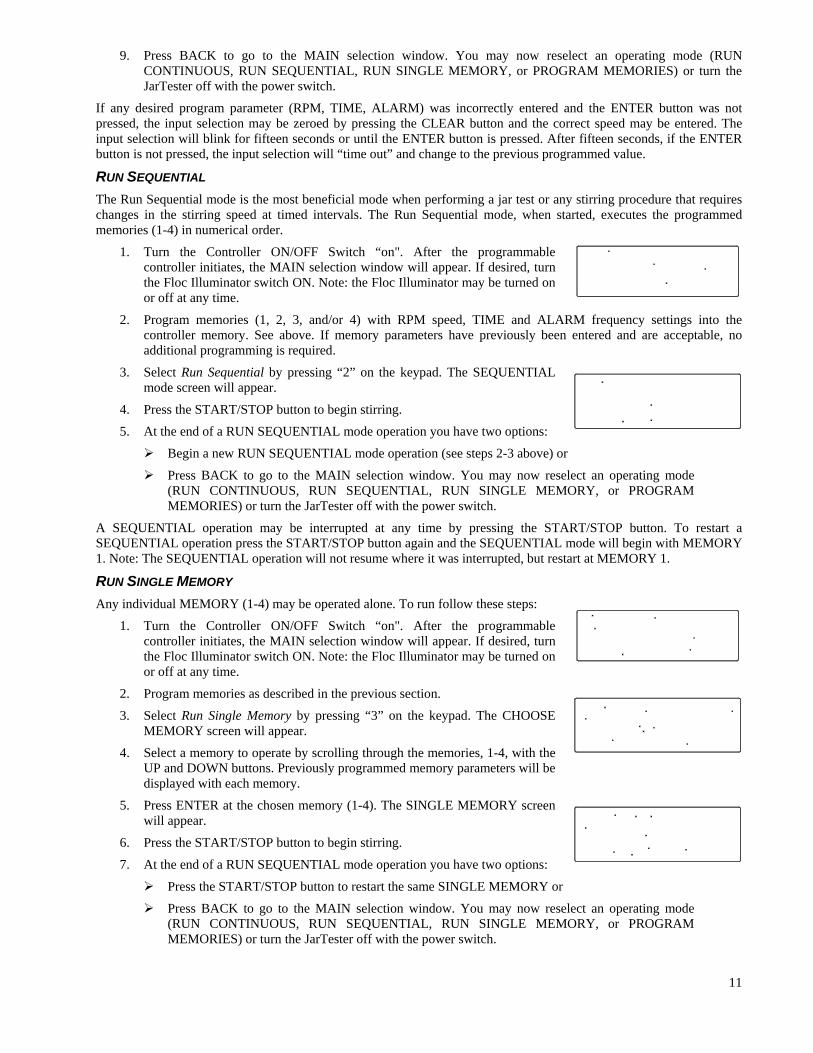
3. Select Run Sequential by pressing “2” on the keypad. The SEQUENTIAL mode screen will appear.
4. Press the START/STOP button to begin stirring.
5. At the end of a RUN SEQUENTIAL mode operation you have two options:
Begin a new RUN SEQUENTIAL mode operation (see steps 2-3 above) or
Press BACK to go to the MAIN selection window. You may now reselect an operating mode (RUN CONTINUOUS, RUN SEQUENTIAL, RUN SINGLE MEMORY, or PROGRAM MEMORIES) or turn the JarTester off with the power switch.
A SEQUENTIAL operation may be interrupted at any time by pressing the START/STOP button. To restart a SEQUENTIAL operation press the START/STOP button again and the SEQUENTIAL mode will begin with MEMORY 1. Note: The SEQUENTIAL operation will not resume where it was interrupted, but restart at MEMORY 1.
RUN SINGLE MEMORY
Any individual MEMORY (1-4) may be operated alone. To run follow these steps:
1. Turn the Controller ON/OFF Switch “on". After the programmable controller initiates, the MAIN selection window will appear. If desired, turn the Floc Illuminator switch ON. Note: the Floc Illuminator may be turned on or off at any time.
2. Program memories as described in the previous section.
3. Select Run Single Memory by pressing “3” on the keypad. The CHOOSE MEMORY screen will appear.
4. Select a memory to operate by scrolling through the memories, 1-4, with the UP and DOWN buttons. Previously programmed memory parameters will be displayed with each memory.
5. Press ENTER at the chosen memory (1-4). The SINGLE MEMORY screen will appear.
6. Press the START/STOP button to begin stirring.
7. At the end of a RUN SEQUENTIAL mode operation you have two options:
Press the START/STOP button to restart the same SINGLE MEMORY or
Press BACK to go to the MAIN selection window. You may now reselect an operating mode (RUN CONTINUOUS, RUN SEQUENTIAL, RUN SINGLE MEMORY, or PROGRAM MEMORIES) or turn the JarTester off with the power switch.

12
EXAMPLE PROGRAM
This section is intended to give a systematic instruction on programming a typical jar test procedure. Your jar test procedure may be different. However, if the operator follows the example he or she should be well acquainted with the programming features so that they can substitute their parameters (RPM speed, run TIME, ALARM frequency) and perform their own unique jar test. This example procedure is merely given as a means of showing how quickly and easily the operator can program their unique procedure.
Example procedure: Flash Mix: 295 r.p.m. for 1 minute and 15 seconds. Floc Mix: 25 r.p.m. for 5 minutes. Settling period: 0 r.p.m. (no agitation) for 10 minutes. Samples will be taken for examination every 2 minutes
The flash mix will be programmed as Memory 1, the Floc Mix will be programmed as Memory 2, and the Settling period will be programmed as Memory 3. For this example, Memory 4 will not be programmed, as it is not needed and will be cleared to ensure it will not operate. To program the above procedure, follow these steps:
1. Turn the Controller ON/OFF Switch “on". After the programmable controller initiates, the MAIN selection window will appear. If desired, turn the Floc Illuminator switch ON. Note: the Floc Illuminator may be turned on or off at any time.
2. Select Program Memories by pressing “4” on the keypad. The CHOOSE MEMORY screen will appear.
3. Press ENTER and the “EDITING VALUES in M1” screen will appear.
4. A blinking cursor will appear beside the programmed RPM speed. Press “295” and ENTER to accept the RPM speed. The blinking cursor will cycle to the next field (TIME).
5. Press “115” and ENTER to accept the run TIME. The blinking cursor will cycle to the next field (ALARM).
6. If there is a value other than zero in the ALARM frequency field press “0” and ENTER. Otherwise, press BACK to go to the CHOOSE MEMORY screen.
7. Press UP and ENTER. The “EDITING VALUES in M2” screen will appear.
8. Press “25” and ENTER to accept the RPM speed.
9. Press “500” and ENTER to accept the run TIME.
10. If there is a value other than zero in the ALARM frequency field press “0” and ENTER. Otherwise, press BACK to go to the CHOOSE MEMORY screen.
11. Press UP twice and ENTER. The “EDITING VALUES in M3” screen will appear.
12. Press “0” and ENTER to accept the RPM speed.
13. Press “1000” and ENTER to accept the run TIME.
14. Press “2” and ENTER to accept the ALARM frequency.
15. Press BACK to go to the CHOOSE MEMORY screen.
16. Press DOWN to go to the “EDITING VALUES in M4”. Review all parameters and verify all values are zeroed. If not, change all values to zero as previously discussed.
17. Press BACK twice to go to the MAIN selection window.
18. Press “2” to select “Run Sequential”.
19. Press the START/STOP button and the PB-900TM JarTester will perform the example procedure outline above.

13
110
2
3
1
7
82
3
9
4
5
6
20. After completion of the programmed procedure, you may either repeat the procedure by pressing START/STOP or press BACK to go to the MAIN selection window. You may then reselect an operating mode (RUN CONTINUOUS, RUN SEQUENTIAL, RUN SINGLE MEMORY, or PROGRAM MEMORIES) or turn the JarTester off with the power switch.
A programmed procedure may be interrupted at any time by pressing the START/STOP button. If so, the procedure could only be restarted from the beginning (Memory 1) or BACK to the MAIN selection window.
The individual memories (1, 2, 3, & 4) are now stored in the controller until they are changed or are cleared as described in Program Memories. (Note: Turning the JarTester off' or unplugging the JarTester from a power source does not erase the programming. Only by changing or clearing a memory will any parameter be altered). In addition, each individual memory may be operated alone. For example, if the operator wished to perform only the Flash Mix (Memory1) as described above, all that would be required is to follow the Run Single Memory as described previously.
REPLACEMENT PARTS - ALL MODELS
ITEM
NO. DESCRIPTION
PART NUMBER
Paddle and Gear Train:
1 Paddle Knob 351000010
2 Paddle Height Adjusting Collar 100472500
3 Driving Dog 977904014
4 Paddle Gear and Shaft 977904012
5 Paddle Shaft 100023302
6 Paddle Blade with Stem 977909008
7 Acorn Nut, 1/4-28 383025028
8 Washer 803025020
9 Idler Gear and Shaft 977904013
10 Thumbscrew 450000041
Items 5 and 6 may be purchased together
Paddle shaft w/ removable blade 977909009
Items 2 and 10 may be purchased together
Paddle Height. Adjusting Collar w/ Thumbscrew
7794-725
Items 1, 2, 5, 6, and 10 may be purchased together
Paddle Assembly Complete 7794-731
Miscellaneous Items:
Power Supply, 100/240VAC to 24VDC 066000056
Acrylic Illuminator Top, 4 Paddle 977909503
Acrylic Illuminator Top, 6 Paddle 977909012
Note: ITEM NO. refers to the numbered items in the adjacent figure.

LIMITED WARRANTY
Phipps & Bird ("the Company") warrants that this equipment will be free from defects in material and workmanship
under normal use and service for a period of one (1) year from the date of shipment. This warranty extends solely to the
registered owner and may not be assigned or otherwise transferred to any other person. The owner must register within
30 days from the date the equipment was purchased. The Company's liability under this warranty is limited solely to
replacing or repairing, at the discretion of the Company, the equipment that is defective; provided, however, that the
Company shall not be liable under this warranty unless (a) the Company is notified promptly in writing, at the address
printed on the warranty card, by the owner, upon the discovery of a defect, (b) if requested by the Company, defective
equipment is promptly returned to the Company, and (c) the Company determines that the malfunction of the equipment
was not caused by misuse, neglect, improper installation, repair, alteration or accident. IN NO EVENT SHALL THE
COMPANY BE LIABLE TO THE OWNER OF THE EQUIPMENT FOR LOSS OF PROFITS, LOSS OF USE,
SPECIAL, INCIDENTAL, OR CONSEQUENTIAL DAMAGES OR DAMAGES OF ANY KIND BASED UPON A
CLAIM FOR BREACH OF WARRANTY, OTHER THAN THE PURCHASE PRICE OF ANY DEFECTIVE
EQUIPMENT COVERED HEREUNDER. This warranty shall not be enlarged, diminished, or affected by, and no
obligation or liability shall arise out of, the rendering of technical advice or service by the Company in connection with
the equipment. Some states do not allow the exclusion or limitation of incidental or consequential damages, so the above
limitations or exclusions may not apply to you. THE FOREGOING IS IN LIEU OF ANY OTHER WARRANTY,
EXPRESSED OR IMPLIED, INCLUDING, WITHOUT LIMITATION, ANY WARRANTY OF
MERCHANTABILITY AND ANY WARRANTY OF FITNESS FOR ANY PARTICULAR PURPOSE. Some states do
not allow limitations on how long an implied warranty lasts, so the above limitations may not apply to you. This
warranty gives you specific legal rights, and you may also have other rights which vary from state to state.
© Phipps & Bird, Inc., 2012 P&B P/N 807000465, REV012/12