january 21st, 2020 - acm
TRANSCRIPT

Channel TSOs proposal of a common capacity calculation methodology for the long-term time frames in accordance with article 10 of Commission Regulation (EU) 2019/1719 of 26 September 2016 establishing a guideline on forward capacity allocation
Page 1 of 22
Channel TSOs proposal of a common capacity calculation methodology for the long-term time
frames in accordance with Article 10 of Commission Regulation (EU) 2019/1719 of 26 September 2016
establishing a guideline on forward capacity allocation
January 21st, 2020

Channel TSOs proposal of a common capacity calculation methodology for the long-term time frames in accordance with article 10 of Commission Regulation (EU) 2019/1719 of 26 September 2016 establishing a guideline on forward capacity allocation
Page 2 of 22
Table of Contents Whereas 3
TITLE 1 General provisions .......................................................................................................................... 6
Article 1 Subject matter and scope ................................................................................................................. 6
Article 2 Definitions and interpretation .......................................................................................................... 6
Article 3 Capacity calculation approach .......................................................................................................... 8
TITLE 2 Requirements for long-term capacity calculations under a statistical-based approach ................. 10
Article 4 General principles ........................................................................................................................... 10
Article 5 Methodology for the statistical long-term capacity calculations ................................................... 10
Article 6 Validation ........................................................................................................................................ 11
TITLE 3 Requirements for long-term capacity calculations under a scenario-based approach ................... 12
Article 7 General principles for long-term cross-zonal capacity calculations ............................................... 12
Chapter 1 Methodologies for the provision of the inputs for calculation ...................................................... 13
Article 8 Critical Network Element and Contingency (CNEC) methodology.................................................. 13
Article 9 Reliability margin methodology ...................................................................................................... 13
Article 10 Methodology for operational security limits .............................................................................. 13
Article 11 Generation shift keys methodology ........................................................................................... 14
Article 12 Methodology for Remedial Actions in capacity calculation ....................................................... 15
Article 13 Scenarios definition methodology ............................................................................................. 15
Article 14 Timestamp selection .................................................................................................................. 15
Chapter 2 Input gathering phase ................................................................................................................... 16
Article 15 Provision of the inputs for the long-term capacity calculations ................................................. 16
Chapter 3 Qualification phase ....................................................................................................................... 17
Article 16 Long-term capacity calculations ................................................................................................. 17
Article 17 Coordinated Net Transmission Capacity process ....................................................................... 17
Article 18 Implementation of reduction of the interconnectors capacity .................................................. 18
Article 19 Implementation of the power shift ............................................................................................ 18
Article 20 N-1 security assessment of maximum import/export for each timestamp of the calculation .. 18
Article 21 Calculation consistency .............................................................................................................. 18
Chapter 4 Validation phase ........................................................................................................................... 19
Article 22 Cross-zonal capacity validation methodology ............................................................................ 19
TITLE 4 Fall-back procedures ..................................................................................................................... 20
Article 23 Fall-back procedures for annual and monthly capacity calculations ......................................... 20
TITLE 5 Publication and implementation ................................................................................................... 21
Article 24 Publication of information ......................................................................................................... 21
Article 25 Implementation of the LT CC Methodology ............................................................................... 21
Article 26 Implementation of new interconnectors ................................................................................... 21
Article 27 Language .................................................................................................................................... 22

Channel TSOs proposal of a common capacity calculation methodology for the long-term time frames in accordance with article 10 of Commission Regulation (EU) 2019/1719 of 26 September 2016 establishing a guideline on forward capacity allocation
Page 3 of 22
All TSOs of the Channel CCR, taking into account the following:
Whereas
1. Commission Regulation (EU) 2016/1719 of 26 September 2016 establishes a guideline on
forward capacity allocation (hereinafter referred to as the “FCA Regulation”), which entered
into force on 17 October 2016.
2. This document is a common proposal developed by all Transmission System Operators
(hereinafter referred to as “TSOs”) within the Channel Capacity Calculation Region (hereinafter
referred to as “Channel CCR”), as defined in accordance with Article 15(1) of Commission
Regulation (EU) 2015/1222 of 24 July 2015 establishing a guideline on capacity allocation and
congestion management (hereinafter referred to as the “CACM Regulation”), on the common
capacity calculation performed for the forward capacity allocation within the long-term time
frames (hereinafter referred to as “LT CC Methodology”). This proposal is required by, and
developed in accordance with, Article 10 of the FCA Regulation.
3. Article 10(1) of the FCA Regulation requires the LT CC Methodology to be submitted within six
months following the approval of the common coordinated capacity calculation methodology
in the Channel CCR referred to in Article 9(7) of the CACM Regulation (hereinafter referred to as
the “Channel Day-Ahead and Intraday Capacity Calculation Methodology”). The TSOs of the
Channel CCR being unable to reach consensus on the LT CC Methodology by the due date, they
informed the national regulatory authorities of the Channel CCR and the Agency for the
Cooperation of Energy Regulators (hereinafter referred to as “the Agency”) on 23 May 2019 and
provided the relevant documentation and information in compliance with Article 4(4) of the FCA
Regulation. Following information to the European Commission by the Agency, the former
provided some guidance which resulted in the TSOs of the Channel CCR being able to reach an
agreement on the main principles of the LT CC Methodology. The TSOs of the Channel CCR were
requested by the European Commission to draft the LT CC Methodology based on these main
principles under an agreed timetable.
4. The LT CC Methodology takes into account the general principles and goals set in the FCA
Regulation.
(a) In accordance with Article 10(2) of the FCA Regulation, the approach to be used is a
coordinated net transmission capacity approach or a flow-based approach. This LT CC
Methodology applies the coordinated net transmission capacity approach which is set up
according to the definition of Article 2(8) of the CACM Regulation.
(b) In compliance with Article 10(3) of the FCA Regulation, the LT CC Methodology shall be
compatible with the Channel Day-Ahead and Intraday Capacity Calculation Methodology.
(c) Article 10(4) of the FCA Regulation requires the uncertainty associated with long-term
capacity calculation time frames to be taken into account when applying either a security
analysis based on multiple scenarios or a statistical approach based on historical cross-
zonal capacity for day-ahead and intraday time frames. Uncertainties have been

Channel TSOs proposal of a common capacity calculation methodology for the long-term time frames in accordance with article 10 of Commission Regulation (EU) 2019/1719 of 26 September 2016 establishing a guideline on forward capacity allocation
Page 4 of 22
considered in Article 9 of this LT CC Methodology.
(d) In accordance with Article 10(6) of the FCA Regulation, where a security analysis based on
multiple scenarios is applied, the requirements for the capacity calculation inputs, the
capacity calculation approach and the validation of cross-zonal capacity as provided for in
Article 21(1) of the CACM Regulation shall apply. These elements have been included in
Articles 8 to 22 of this LT CC Methodology.
(e) In accordance with Article 10(7) of the FCA Regulation and Article 21(3) of the CACM
Regulation, fallback procedures have been developed in Article 23 of this LT CC
Methodology.
(f) Article 4(8) of the FCA Regulation requires that the proposed timescale for the
implementation and the expected impact of the LT CC Methodology on the objectives of
the FCA Regulation is described. They are respectively presented in Article 25 and in recital
5 of this Whereas Section.
5. The LT CC Methodology contributes to and does not in any way hinder the achievement of the
objectives of Article 3 of the FCA Regulation. In particular, the LT CC Methodology:
(a) Establishes common and coordinated processes for the capacity calculations by defining a
set of harmonised rules for long-term cross-zonal capacity calculation, seeking to release
capacity at the earliest possible time. As such, this serves the objective of promoting
effective long-term cross-zonal trade with long-term cross-zonal hedging opportunities for
market participants in accordance with Article 3(a) of the FCA Regulation;
(b) Contributes to the objective of optimising the calculation and allocation of long-term cross-
zonal capacity in accordance with Article 3(b) of the FCA Regulation by coordinating the
timings for the delivery of inputs, the calculation approach and the validation
requirements;
(c) Contributes to the objective of providing non-discriminatory access to long-term cross-
zonal capacity in accordance with Article 3(c) of the FCA Regulation by ensuring that the
capacity calculation is available to all market participants and is transparent;
(d) Contributes to the objective of ensuring fair and non-discriminatory treatment of TSOs, the
Agency, regulatory authorities and market participants in accordance with Article 3(d) of
the FCA Regulation by reducing long-term uncertainties in respect of cross-zonal capacities;
(e) Contributes to the objective of respecting the need for a fair and orderly forward capacity
allocation and orderly price formation in accordance with Article 3(e) of the FCA Regulation
by providing market participants with information on the quantity of long-term cross-zonal
capacity that can be released and the reduction periods (if any);
(f) Contributes to the objective of ensuring and enhancing the transparency and reliability of
information on forward capacity allocation in accordance with Article 3(f) of the FCA
Regulation by coordinating the inputs of the capacity calculation and requiring these inputs
to be transparent;
(g) Contributes to the efficient long-term operation and development of the electricity

Channel TSOs proposal of a common capacity calculation methodology for the long-term time frames in accordance with article 10 of Commission Regulation (EU) 2019/1719 of 26 September 2016 establishing a guideline on forward capacity allocation
Page 5 of 22
transmission system and electricity sector in the Union in accordance with Article 3(g) of
the FCA Regulation by providing TSOs and market participants with information on cross-
border availability in a timely manner and ensuring that the results of each capacity
calculation are based on the best possible forecast of the transmission systems at that
point in time. Furthermore, this LT CC Methodology outlines how future interconnectors
joining the Channel CCR would be incorporated within the capacity calculation.
SUBMIT THE FOLLOWING LT CC METHODOLOGY TO ALL NATIONAL REGULATORY AUTHORITIES OF
THE CHANNEL CCR:

Channel TSOs proposal of a common capacity calculation methodology for the long-term time frames in accordance with article 10 of Commission Regulation (EU) 2019/1719 of 26 September 2016 establishing a guideline on forward capacity allocation
Page 6 of 22
TITLE 1 General provisions
Article 1 Subject matter and scope
1. The common capacity calculation methodology as determined in this LT CC Methodology is the
common proposal of all the TSOs of the Channel CCR in accordance with Article 10(1) of the FCA
Regulation.
2. This LT CC Methodology applies solely to the long-term capacity calculations within the Channel
CCR. Common capacity calculation methodologies within other capacity calculation regions or
other timeframes are outside the scope of this proposal.
3. The LT CC Methodology covers the annual and monthly long-term time frames pursuant to
Article 9 of the FCA Regulation.
4. The methodology for splitting long-term cross-zonal capacity is out of scope of this LT CC
Methodology but in the scope of the methodology pursuant to Article 16 of the FCA Regulation.
Article 2 Definitions and interpretation
1. For the purposes of the LT CC Methodology, the terms used shall have the meaning given to
them in Article 2 of Regulation (EC) 714/2009, Article 2 of Regulation (EC) 2013/543 and Article
2 of the FCA Regulation.
2. In addition, the following definitions shall apply:
CC Capacity Calculation
CCC Coordinated Capacity Calculator, as defined in Article 2(11) of the
CACM Regulation
CCR Capacity Calculation Region, as defined in article 2(3) of the CACM
Regulation
CGM Common Grid Model, as defined in Article 2(2) of the CACM Regulation
CGMM
Common Grid Model Methodology, as requested by Article 17(1) of
the CACM Regulation
CNE Critical Network Element
CNEC Critical Network Element and Contingency
cNTC Coordinated Net Transmission Capacity, as defined in Article 2(8) of the
CACM Regulation
Day-Ahead Has the meaning given to in Article 2(34) of the CACM Regulation

Channel TSOs proposal of a common capacity calculation methodology for the long-term time frames in accordance with article 10 of Commission Regulation (EU) 2019/1719 of 26 September 2016 establishing a guideline on forward capacity allocation
Page 7 of 22
EC European Commission
ENTSO-E European Network of Transmission System Operators for Electricity
EU European Union
Fmax Maximum Allowable Power Flow
FRM Flow Reliability Margin
GSK Generation Shift Key, as defined in article 2(12) of the CACM
Regulation
HVDC High-Voltage Direct Current
𝐼max Maximum Admissible Current
Import/export limit Limits of the net position of a bidding zone
LT Long-Term
LTA Long-Term Allocated capacity
Maximum Secure
Value
The maximum power transfer between two adjacent Bidding Zones
respecting the operational security (no negative margin on the
relevant CNECs)
Minimum
Guaranteed Value
Minimum of the calculated values during the first annual cross-zonal
capacity calculation under a scenario-based approach
MPTC Maximum Permanent Technical Capacity. For the avoidance of doubt,
it means, for the relevant market time unit(s), the maximum
permanent technical capacity which is the maximum continuous active
power which a cross-zonal network element (interconnector/HVDC
system) is capable of transmitting (taking into account potential
reduced availability due to planned and unplanned outages of the
interconnector asset). This parameter is defined by the
interconnector’s asset operators, and only considers the
interconnector asset availability
NRA National Regulatory Authority
NTC Net Transmission Capacity
PTDF Power Transfer Distribution Factor

Channel TSOs proposal of a common capacity calculation methodology for the long-term time frames in accordance with article 10 of Commission Regulation (EU) 2019/1719 of 26 September 2016 establishing a guideline on forward capacity allocation
Page 8 of 22
Remedial Action Has the meaning given to it in Article 2(13) of the CACM Regulation
RoCoF Rate of Change of Frequency
SO GL Commission Regulation (EU) 2017/1485 of 2 August 2017 establishing
a guideline on electricity transmission system operation
3. In this LT CC Methodology, unless the context requires otherwise:
(a) the singular indicates the plural and vice versa;
(b) headings are inserted for convenience only and do not affect the interpretation of this
proposal; and
(c) any reference to legislation, regulations, directives, orders, instruments, codes or any other
enactment shall include any modification, extension or re-enactment of it when in force.
Article 3 Capacity calculation approach
1. This LT CC Methodology is based on a cNTC approach in accordance with Article 10(2) of the FCA
Regulation and uses both statistical and scenario-based calculations.
2. This LT CC Methodology is composed of three steps in respect of the annual capacity calculation:
i. A statistical calculation performed by the CCC by end of February Y-1. This calculation shall
result in a single NTC value per interconnector and per direction with potential reduction
periods. Once the calculation is completed, the capacity can be allocated to the market in
the form of long term auctions subject to Article 16 of the FCA Regulation;
ii. A first scenario-based calculation performed by the CCC by the end of September Y-1. This
calculation shall result in a single NTC value per interconnector and per direction without
additional reduction periods, which is the Minimum Guaranteed Value (MGV). The MGV
represents the capacity which is guaranteed during the whole period except at times of
interconnector outages. Once the calculation is completed, the capacity up to the MGV
(which has not been already allocated) can be allocated to the market in subsequent long-
term auctions subject to Article 16 of the FCA Regulation;
iii. A second scenario-based calculation performed by the CCC in December Y-1. This
calculation shall release the MPTC subject to potential reduction periods. The calculation
is optional in the event that no updated or additional input data is received. If the
calculation is not performed, MPTC shall be released with the potential reduction periods
included in the first scenario-based calculation. Once the calculation is completed, the
capacity up to the MPTC of the interconnector or the capacity calculated during the
reduction periods (which has not been already allocated) can be allocated to the market
in subsequent long-term auctions subject to Article 16 of the FCA Regulation.

Channel TSOs proposal of a common capacity calculation methodology for the long-term time frames in accordance with article 10 of Commission Regulation (EU) 2019/1719 of 26 September 2016 establishing a guideline on forward capacity allocation
Page 9 of 22
3. This LT CC Methodology is composed of a single step in respect of the monthly capacity
calculation:
i. A Monthly capacity scenario-based calculation performed by CCC before the end of the
month M-2.
4. Capacity allocation for all long-term products will be based on the latest calculated results.
5. For products with a duration greater than one month, the capacity will be derived from annual
capacity calculations. For products with a duration equal to or less than one month, the capacity
will be derived from monthly capacity calculations.

Channel TSOs proposal of a common capacity calculation methodology for the long-term time frames in accordance with article 10 of Commission Regulation (EU) 2019/1719 of 26 September 2016 establishing a guideline on forward capacity allocation
Page 10 of 22
TITLE 2 Requirements for long-term capacity calculations
under a statistical-based approach
Article 4 General principles
A volume of annual cross-zonal capacity is to be made available before the end of February preceding
the delivery year. Due to the unavailability of the input data for a scenario-based approach in
accordance with Article 3(1) of CGMM for forward capacity allocation in conjunction with Article 65
of SO GL before this deadline, annual cross-zonal capacities will be calculated under a statistical-based
approach. The result of the capacity calculation will be validated in accordance with the validation
conditions described in Article 6 but will be capped at 35% of the interconnector MPTC.
Article 5 Methodology for the statistical long-term capacity calculations
The CCC shall calculate the annual cross-zonal capacity for each interconnector and direction on a
bidding zone border as follows:
1. Obtain the last 2 years’ worth of Day-Ahead NTC data per interconnector and per direction.
2. Take the average of those NTC values.
3. Calculate the value equal to 50% of the average value in order to take account of:
(a) Removing LTA inclusion;
(b) Removing the impact of intraday as a Remedial Action (in Great Britain only);
(c) Removing the impact of countertrading; and
(d) Adding a margin to reflect the difference between historical cross-zonal capacity values
and forecasted long-term cross-zonal capacity values as required by Article 23 (1)(c) of the
FCA Regulation.
4. Where the resulting value is above 35% of the interconnector MPTC, the applied capacity is 35%
of the interconnector MPTC.
5. Where the resulting value is below 35% of the interconnector MPTC, either the resulting capacity
of <35% of the interconnector MPTC is applied in case this is justified in line with Article 6(2), or
the applied capacity is increased to 35% of the interconnector MPTC.
6. The value calculated in Article 5(4) or Article 5(5) is subject to validation as described in Article 6.
Any new interconnector that does not have two full years of day-ahead data to complete the
calculation described in Article 5, will be given either of the following:
(a) In case the new interconnector shares some limiting CNEs with an existing interconnector, the value calculated for this existing interconnector.
(b) Otherwise, 35 % of the interconnector MPTC.
This value shall be validated in accordance with Article 6.

Channel TSOs proposal of a common capacity calculation methodology for the long-term time frames in accordance with article 10 of Commission Regulation (EU) 2019/1719 of 26 September 2016 establishing a guideline on forward capacity allocation
Page 11 of 22
Article 6 Validation
1. TSOs of the Channel CCR have the responsibility to validate the capacity proposed by the CCC
and subject to Article 6(2) or Article 6(3), may locally re-assess the computed NTCs per
interconnector.
2. If the result of the calculation described in Article 5 gives a value lower than 35% of the
interconnector MPTC, the concerned TSOs may reduce the applied capacity below 35% of the
interconnector MPTC but not lower than the value calculated in Article 5. A justification for the
reduction shall be sent to the relevant NRAs.
3. TSOs may reduce the applied capacity below 35% of the interconnector based on planned
outages, new infrastructure and generation and load pattern for the long-term capacity
calculation time frames in accordance with Article 23(1)(d) of the FCA Regulation. The reduction
shall be incorporated in the long-term products as reduction periods. The level of reduction shall
be duly justified based on an individual analysis to demonstrate that additional capacity would
cause operational security concerns and this analysis must be presented to the TSOs of bidding
zone border and shall be sent to the relevant NRAs. This analysis must be performed in a timely
manner in order to release forward cross-zonal capacity before the end of February preceding
the delivery year.
4. In case several interconnectors influence similar CNECs in the same control area, any reductions
on these interconnectors shall be done proportionally to their influence on the limiting CNECs.
5. The TSOs of the Channel CCR shall report to NRAs any NTC reduction resulting from the
validation phase.
Channel TSOs proposal of a common capacity calculation methodology for the long-term time frames in accordance with article 10 of Commission Regulation (EU) 2019/1719 of 26 September 2016 establishing a guideline on forward capacity allocation
Page 12 of 22
TITLE 3 Requirements for long-term capacity calculations under
a scenario-based approach
Article 7 General principles for long-term cross-zonal capacity calculations
1. For the long-term time frames, the CCC shall calculate the cross-zonal capacity for each
interconnector on a bidding zone border and for each timestamp selected in accordance with
Article 14 of this LT CC Methodology in respect of each long-term calculation using the cNTC
approach.
2. Following the long-term statistical calculation occurring before the end of February Y-1, three
different long-term calculations under a scenario-based approach will be performed in the
following order:
(a) Annual capacity calculation using a Minimum Guaranteed Value before the end of
September Y-1;
(b) Annual capacity calculation releasing the interconnector MPTC while using reduction
periods in December Y-1; and
(c) Monthly capacity calculation using reduction periods before the end of the month M-2.
3. The timestamps that will be used are the ones during which one or several outage(s) on a CNE
is/are planned by an onshore TSO in one of the bidding zones. For timestamps without any
planned outage on any CNE the calculation will give the interconnector MPTC except in respect of
the calculation described in Article 7(2)(a) in which the lower value of each calculation over the
period (excluding interconnectors outages) will be taken. The planned outages of an onshore TSO
with a significant impact on the interconnector in one of the bidding zones to which that
interconnector is connected shall be defined as follows:
(a) A planned outage on one CNE satisfying the requirements set out in Article 8; and
(b) Any other pre-determined conditions defined by the TSO, agreed with all Channel NRAs
and published on the TSO’s website before its application. In such a case, the concerned
TSO shall explicitly publish without delay on its website the list of concerned grid
elements and the estimated duration of the application of this specific grid condition
when known.
4. Each onshore TSO shall publish on its website the list of the grid elements resulting from the
selection criteria under Article 8.
5. The long-term capacity calculation shall be composed of the following three phases in
accordance with Article 10(6) of the FCA Regulation: the input gathering phase as described in
Chapter 2, the qualification phase as described in Chapter 3 and the validation phase as
described in Chapter 4.

Channel TSOs proposal of a common capacity calculation methodology for the long-term time frames in accordance with article 10 of Commission Regulation (EU) 2019/1719 of 26 September 2016 establishing a guideline on forward capacity allocation
Page 13 of 22
Chapter 1 Methodologies for the provision of the inputs for
calculation
Article 8 Critical Network Element and Contingency (CNEC) methodology
1. Each TSO of the Channel CCR shall perform the selection of the CNECs based on the assessment
of the cross-zonal flow sensitivity.
2. For the Channel CCR, the cross-zonal flow sensitivity shall correspond to maximum of the
following bidding zone to bidding zones PTDF absolute value:
(a) Great Britain to France;
(b) Great Britain to Belgium;
(c) Great Britain to The Netherlands.
3. According to Article 23(2) of the FCA Regulation, each TSO of the Channel CCR shall consider as
not significantly influenced the CNECs with cross-zonal flow sensitivity below a certain
threshold. Those not significantly influenced CNECs shall be ignored for the cross-zonal capacity
calculation.
4. The cross-zonal flow sensitivity threshold for the LT CC methodology in the Channel CCR is
identical to the threshold for the DA/ID CC methodology in the Channel CCR.
5. Each TSO of the Channel CCR shall monitor the CNECs to assess the relevance of the sensitivity
threshold over time.
6. Each TSO of the Channel CCR shall critically assess the relevance of the CNECs against its CNEC
selection criteria and may decide to discard some of the CNEC from the list. This must be based
on a study performed by the TSO or operational experience.
Article 9 Reliability margin methodology
1. The TSOs of the Channel CCR consider that the additional uncertainties between the long-term
and Day-Ahead time frames are covered by the selected scenarios, therefore long-term capacity
calculations will use the same Flow Reliability Margin applied in the Channel Day-Ahead and
Intraday Capacity Calculation Methodology.
2. Determination of a reliability margin does not apply to direct current interconnections due to
their controllability.
3. The TSOs of the Channel CCR shall maintain consistency between the Day Ahead/Intraday and
Long Term timescales by aligning the same FRM in a timely manner.
Article 10 Methodology for operational security limits
In accordance with Article 12 of the FCA Regulation:

Channel TSOs proposal of a common capacity calculation methodology for the long-term time frames in accordance with article 10 of Commission Regulation (EU) 2019/1719 of 26 September 2016 establishing a guideline on forward capacity allocation
Page 14 of 22
1. Each TSO within the Channel CCR shall define at least per season (spring, summer, autumn &
winter) and for each CNE the maximum permanent allowable current according to its
operational security limits criteria defined in line with Article 25 of SO GL.
2. The TSOs of the Channel CCR shall maintain consistency with their neighbouring CCRs in a timely
manner. TSO of the Channel CCR who are also active in neighbouring CCRs shall apply the
operational security limits identical to those in the neighbouring CCRs.
3. The TSOs of the Channel CCR applying the security constraint on the bidding zone import/export
limits shall provide this information to the CCC as an input data for the relevant capacity
calculations.
Article 11 Generation shift keys methodology
1. The TSOs of Channel CCR shall define the generation shift keys (GSK) for long-term time frames
in accordance with Article 13 of the FCA Regulation.
2. The GSK in Great Britain shall represent the best forecast of the relation of a change in net
position of the bidding zone to a specific change of generation or load in the CGM.
3. The French GSK will be composed of all the units connected to RTE’s network which are relevant
for this long-term time frame. The variation of the generation pattern inside the GSK is the
following: all the units which are in operations in the base case will follow the change of the
French net position on a pro-rata basis. This means, if for instance one unit is representing n%
of the total generation on the French grid, n% of the shift of the French net position will be
attributed to this unit.
4. The Belgian GSK shall be determined for the Belgian bidding zone based on a defined list of
nodes located where the most relevant flexible and controllable production units are
connected. This list shall be defined in a way to limit as much as possible the impact of model
limitations on the loading of the CNEs. The variation of the generation pattern inside the GSK
shall be such that for each of these nodes, the sum of the generation units which are in
operations on each of these nodes in the CGM will follow the change of the Belgian net position
in such a way that the generation at the node will reach its maximum when the maximum
generation capability of the Belgian bidding zone is reached and will reach its minimum when
the minimum generation capability of the Belgian bidding zone is reached.
5. The Dutch GSK will dispatch the main generators in a manner which avoids extensive and
unrealistic under- and overloading of the units for extreme import or export scenarios. The GSK
is directly adjusted in case of new power plants. In addition, unavailability of generators due to
outages is considered in the GSK. All GSK units are re-dispatched pro-rata on the basis of
predefined maximum and minimum production levels for each active unit. The total production
level remains the same. The maximum production level is the contribution of the unit in a
predefined extreme maximum production scenario. The minimum production level is the
contribution of the unit in a predefined extreme minimum production scenario. Base-load units
will have a smaller difference between their maximum and minimum production levels than
start-stop units.

Channel TSOs proposal of a common capacity calculation methodology for the long-term time frames in accordance with article 10 of Commission Regulation (EU) 2019/1719 of 26 September 2016 establishing a guideline on forward capacity allocation
Page 15 of 22
Article 12 Methodology for Remedial Actions in capacity calculation
1. Each TSO of the Channel CCR shall define individually the Remedial Actions, used for the
calculation defined in Article 17, that shall be made available for the long-term capacity
calculation within the Channel CCR in accordance with Article 14 of the FCA Regulation. Each
TSO of the Channel CCR shall, at minimum, ensure that all relevant non-costly Remedial Actions
according to the TSOs’ operational principles which are anticipated to be available on the day
of delivery are made available to the CCC. The type of non-costly remedial action shall cover,
among others, topological changes and phase shifting transformer tap changes.
2. Each TSO of the Channel CCR may decide to make available costly Remedial Actions.
3. When defining a Remedial Action, each TSO of the Channel CCR shall specify at minimum:
(a) The type of the Remedial Action and the sequence of actions to be implemented;
(b) In case of quantifiable Remedial Action, the maximum and minimum values of the scalable
quantity; and
(c) Whether the Remedial Action is a shared Remedial Action and can be considered for all
contingencies or whether it shall be limited to a subset of contingencies. In the latter case,
the TSO shall specify the list of contingencies.
4. In case a Remedial Action made available for the long-term capacity calculation in the Channel
CCR is also one which is made available in another CCR, the TSO taking control for the Remedial
Action shall take care when defining it of a consistent use in its potential application in both
CCRs to ensure a secure power system operation.
Article 13 Scenarios definition methodology
1. In accordance with Article 19 of the FCA Regulation, all TSOs in the Channel CCR shall jointly
develop a common set of scenarios to be used in the CGM for each long-term capacity
calculation time frame.
2. In order to meet the above requirements, the TSOs of the Channel CCR shall use the ENTSO-E
year-ahead reference scenarios which are created on an annual basis (i.e. default scenarios), in
line with Article 3.1 of CGMM developed according to Articles 67(1) and 70(1) of SO GL. This
pan-European process is based on the common grid methodology as developed in accordance
with Article 18 of the FCA Regulation.
3. ENTSO-E year-ahead reference scenarios can be updated by each TSO of the Channel CCR at a
monthly level to incorporate the latest available information with regard to the generation
pattern.
Article 14 Timestamp selection
1. Long-term cross-zonal capacity will be computed only in respect of the periods including a
planned outage of a CNE with significant impact on the interconnector.

Channel TSOs proposal of a common capacity calculation methodology for the long-term time frames in accordance with article 10 of Commission Regulation (EU) 2019/1719 of 26 September 2016 establishing a guideline on forward capacity allocation
Page 16 of 22
2. The outage planning of the CNEs listed before is available through the Outage Planning
Coordination database according to Articles 97, 98 & 99 of SO GL. Based on this database, the
timestamp selection will use the outage planning of the CNEs of the Channel CCR as follows:
(a) Timestamps will be selected per granularity of the concerned period. This granularity is
fixed in advance and is the following:
i. 1 month for the annual cNTC calculation;
ii. 1 week for the monthly cNTC calculation.
(b) The selected timestamp within the granularity is the day with the largest simultaneous
number of planned outages.
(c) In case two or more timestamps take place within the same scenario and contain the same
planned outages, those redundant timestamps will be ignored. The outcome of the
calculation will be considered equal for the two timestamps without an additional
calculation.
(d) In case there is no planned outage within the granularity or redundancy occurs, no
timestamp is selected. Instead, a second timestamp within another granularity can be
selected.
(e) As the timestamp selection is mainly driven by the number of simultaneous outages and
not by the impact of the outages, the TSO may request extra timestamps.
3. The timestamp selections based on the outage planning of the CNE in the Channel CCR is
proposed by the CCC to the TSOs sufficiently in advance of each annual calculation and each
monthly calculation.
4. In case the CCC has no access to the outage planning, then the CCC requests the individual
outage planning sufficiently in advance to the concerned TSOs prior to the relevant calculation.
5. After the standard timestamps are selected, TSOs can send their request of additional ad-hoc
timestamps to the CCC.
6. For each selected timestamp, the CCC will generate a CGM in accordance with the CGMM
related to Article 18 of the FCA Regulation and shall include the planned outages according to
Article 14(2)(b).
Chapter 2 Input gathering phase
Article 15 Provision of the inputs for the long-term capacity calculations
1. The TSOs of the Channel CCR shall provide the CCC before a deadline commonly agreed between
the TSOs and the CCC the following inputs:
(a) Generation Shift Key in accordance with Article 11;
(b) Maximum Permanent Technical Capacity in accordance with Article 2(2);

Channel TSOs proposal of a common capacity calculation methodology for the long-term time frames in accordance with article 10 of Commission Regulation (EU) 2019/1719 of 26 September 2016 establishing a guideline on forward capacity allocation
Page 17 of 22
(c) Critical Network Elements and Contingencies in accordance with Article 8;
(d) Flow Reliability Margin in accordance with Article 9;
(e) Maximum admissible current on a CNE (Imax) / Maximum allowable power flow (Fmax) in
accordance with Article 10;
(f) Remedial Actions in accordance with Article 12; and
(g) Ad hoc timestamp in accordance with Article 14.
2. When providing the inputs, the TSOs of the Channel CCR shall respect the formats commonly
agreed between the TSOs of the Channel CCR and the CCCs.
Chapter 3 Qualification phase
Article 16 Long-term capacity calculations
The CCC shall calculate, subject to Art.20, the following:
(a) the maximum secure value of simultaneous import of the synchronous grid of Continental
Europe ; and
(b) the maximum secure value of simultaneous export of the synchronous grid of Continental
Europe,
over all the interconnectors of the Channel CCR bidding zone borders, for each timestamp following
the process outlined in Article 14.
Article 17 Coordinated Net Transmission Capacity process
1. The CCC shall prepare the CGM for the timestamps selected according to Article 14 and shall use
GSKs according to Article 11 for each scenario timestamp in order to reflect the starting point by
setting the exchanges on the interconnectors at the level of their MPTC in the direction of the
synchronous grid of Continental Europe towards Great-Britain or vice versa.
2. The CCC shall run a contingency analysis on the CGM using the CNEC list provided by the TSOs
and evaluate results either allowing interconnector MPTC without further actions or indicating
a potential interconnector import or export limitation as a result of a negative margin on a CNE
or operational security standard violation.
3. For each negative margin on a CNE, the CCC shall deploy the list of Remedial Actions to alleviate
such a margin. If Remedial Actions can alleviate the negative margin of the CNE, the
interconnector MPTC can be made available for that scenario timestamp. If the Remedial
Actions used in this respect cannot alleviate the CNE violation, the maximum secure value of the
interconnector capacity of the bidding zone where the limiting CNEC(s) is/are located should be
progressively reduced in steps from starting points according to Article 18. Following each
reduction, the contingency analysis should be repeated with the Remedial Actions already
deployed until a level of the maximum secure value of the interconnector capacity has been
identified for which no CNE violations occur.

Channel TSOs proposal of a common capacity calculation methodology for the long-term time frames in accordance with article 10 of Commission Regulation (EU) 2019/1719 of 26 September 2016 establishing a guideline on forward capacity allocation
Page 18 of 22
Article 18 Implementation of reduction of the interconnectors capacity
1. For each timestamp, the CCC shall perform a reduction of the interconnector capacity as follows:
(a) In case of negative margin on the CNECs which cannot be solved with available Remedial
Actions, the CCC shall in his calculation reduce the capacity of the Interconnector
connected to the bidding zone where the limiting CNE is located.
(b) In case several interconnectors are located in the concerned bidding zone, the reduction
shall be applied only to the interconnectors which have an influence on the limiting CNE
above the thresholds defined in Article 8 and proportionally to their influence.
2. In case of a calculation resulting in a Minimum Guaranteed Value following Article 7(2)(a), the
most significant reduction of capacity of all scenario timestamps, with exception of the
interconnector outages, will be the NTC value of the interconnector for the entire time frame
under calculation.
3. In case of a calculation resulting in the MPTC including reduction period(s) following Article
7(2)(b) or Article 7 (2)(c), the reduction of capacity, with exception of the interconnector
outages, will apply for the entire duration of the relevant reduction period.
Article 19 Implementation of the power shift
When computing the capacity, the CCC shall implement any shift of the power transfer between two
bidding zones by adjusting the generation in each of the bidding zones using the GSK of the bidding
zones.
Article 20 N-1 security assessment of maximum import/export for each timestamp of the
calculation
The CCC shall perform N-1 security assessments for the timestamps selected in accordance with Article
14.
Article 21 Calculation consistency
1. For the first scenario-based cross-zonal long-term calculation (resulting in a Minimum Guaranteed
Value), for each interconnector in both import and export directions, the maximum value between
the results obtained under the statistical-based approach in Article 6 and the results obtained
under the first scenario-based approach in Article 18 shall be taken as the capacity to be validated
in accordance with Chapter 4. This means that the Minimum Guaranteed Value resulting from the
calculation described in Article 7(2)(a) cannot be lower than the relevant value validated under
the statistical-based approach in Article 6.
2. For each remaining long-term calculation, for each interconnector in both import and export, the
maximum value between the results obtained in Article 18 and the long-term Allocated capacity
(LTA) corresponding to the studied timestamp shall be taken as the capacity to be validated for
the reduction periods in accordance with Chapter 4.

Channel TSOs proposal of a common capacity calculation methodology for the long-term time frames in accordance with article 10 of Commission Regulation (EU) 2019/1719 of 26 September 2016 establishing a guideline on forward capacity allocation
Page 19 of 22
Chapter 4 Validation phase
Article 22 Cross-zonal capacity validation methodology
1. The TSOs of the Channel CCR have the responsibility to validate the capacity proposed by the
CCC and subject to paragraph 2 below, may locally re-assess the computed NTCs on the
interconnector.
2. The TSOs of the Channel CCR have the right to re-assess the capacity calculated to prevent any
risk due to possible unforeseen changes in grid situations which have occurred during the
qualification phase such as:
(a) Forced outage on one interconnector or one element defined as CNE or contingency;
(b) A mistake in input data leading to an incorrect cross-zonal capacity; and/or
(c) Any other criteria that the TSO shall have previously defined, agreed by its NRA and
published in its website before its application.
3. In case of such possible unforeseen changes and should a TSO is detect a constraint, the TSOs
of the Channel CCR may have to reject the calculated NTCs on the interconnector(s) of its bidding
zone. Those TSOs shall be entitled to reduce the proposed NTC towards its own interconnector.
4. The reduction of the proposed NTCs shall be monitored, based at minimum on an identification
of the limiting CNEC and the explanation of the unforeseen event causing the NTC reduction.
Under these circumstances, the output of this process is the amended NTC which is considered
as the final NTC.
5. The TSOs of the Channel CCR shall report to NRAs any NTC reduction resulting from the
validation phase and the related CNEC.

Channel TSOs proposal of a common capacity calculation methodology for the long-term time frames in accordance with article 10 of Commission Regulation (EU) 2019/1719 of 26 September 2016 establishing a guideline on forward capacity allocation
Page 20 of 22
TITLE 4 Fall-back procedures
Article 23 Fall-back procedures for annual and monthly capacity calculations
1. In accordance with Article 42 of the FCA Regulation, in the event that the CCC is unable to
produce results, the default fall-back procedure shall be the postponement of the forward
capacity allocation and a reasonable deadline shall be agreed by the TSOs of the Channel CCR
to rerun the calculation.
2. In case the postponement of the forward capacity allocation is not possible, or the new deadline
has been reached and no results are available, the TSOs of the Channel CCR foresee the
following fall-back process:
(a) For the annual capacity calculation, the TSOs will use as a starting point cross-zonal long-
term capacity calculated by the CCC for the equivalent planned outages of the previous
year. The TSOs of the Channel CCR will bilaterally validate these NTC values and then these
values will be validated in a coordination meeting of the TSOs of the Channel CCR.
(b) For the monthly capacity calculation, the TSOs of the Channel CCR will use as a starting
point cross-zonal long-term capacity calculated by the CCC during the annual process for
this month. The TSOs of the Channel CCR will bilaterally validate these NTC values and then
these values will be validated in a coordination meeting of the TSOs of the Channel CCR.

Channel TSOs proposal of a common capacity calculation methodology for the long-term time frames in accordance with article 10 of Commission Regulation (EU) 2019/1719 of 26 September 2016 establishing a guideline on forward capacity allocation
Page 21 of 22
TITLE 5 Publication and implementation
Article 24 Publication of information
1. In accordance with Article 3(f) and Article 21(3) of the FCA Regulation, all TSOs of the Channel
CCR shall regularly and at least once a year review and update the key input and output
parameters listed in Article 27(4)(a) to (d) of the CACM Regulation.
(a) If the operational security limits and contingencies used for the capacity calculation need
to be updated based on this review, the TSOs of the Channel CCR shall publish the changes
at least one week before the implementation.
(b) The TSOs of the Channel CCR shall include the re-assessment of the further need of security
constraints.
2. The review of the common list of Remedial Actions taken into account in the capacity calculation
shall include at least an evaluation of the efficiency of specific phase-shifting transformers and
the topological Remedial Actions considered.
3. In case the review proves the need for updating the application of the methodologies in respect
of CNECs and GSKs referred to in Articles 12 and 13 of the FCA Regulation, referring respectively
to the Articles 23 to 24 of the CACM Regulation, changes will have to be published at least three
months before the final implementation.
4. Any changes of parameters listed in Article 27(4) of the CACM Regulation have to be
communicated to market participants and the NRAs of the Channel CCR.
Article 25 Implementation of the LT CC Methodology
1. The TSOs of the Channel CCR shall publish the LT CC Methodology without undue delay after all
NRAs have approved the proposed LT CC Methodology or a decision has been taken by the
Agency for the Cooperation of Energy Regulators in accordance with Article 4(9), Article 4(10)
and 4(11) of the FCA Regulation.
2. The TSOs of the Channel CCR shall implement the LT CC Methodology for the capacity calculation
performed in annual and monthly time frames no later than 12 months after the go-live of
Channel Day-Ahead and Intraday Capacity Calculation.
3. The deadline defined in Article 25(2) can be modified on request of all TSOs of the Channel CCR
in case the testing results of the testing period do not meet the necessary conditions for
implementation.
4. During the implementation period, and especially in case of new interconnector, each TSO may
apply a stepwise implementation of the LT CC Methodology for the interconnectors connected
to its bidding zone.
Article 26 Implementation of new interconnectors
1. The LT CC Methodology will apply by default to new interconnectors in case no need for
amendment is identified by the TSOs of the Channel CCR.

Channel TSOs proposal of a common capacity calculation methodology for the long-term time frames in accordance with article 10 of Commission Regulation (EU) 2019/1719 of 26 September 2016 establishing a guideline on forward capacity allocation
Page 22 of 22
2. The TSOs of the Channel CCR shall jointly discuss, and not unreasonably withhold, proposed
amendments to the LT CC Methodology required for a new interconnector joining the Channel
CCR.
Article 27 Language
1. The reference language for this LT CC Methodology shall be English.
2. For the avoidance of doubt, where TSOs need to translate this LT CC Methodology into their
national language(s), in the event of inconsistencies between the English version published by
TSOs in accordance with Article 4(13) of the FCA Regulation and any version in another language,
the relevant TSOs shall be obliged to eliminate any inconsistencies by providing a revised
translation of this LT CC Methodology to their relevant NRAs.

Explanatory note for the proposal of the LT CC Methodology for the Channel CCR
Page 1 of 28
Explanatory note for Channel TSOs proposal of common capacity calculation methodology for the long-term market timeframe in accordance with
Article 10 of Commission Regulation (EU) 2019/1719 of 26 September 2016 establishing a
guideline on forward capacity allocation
January 21st, 2020

Explanatory note for the proposal of the LT CC Methodology for the Channel CCR
Page 2 of 28
Disclaimer
This explanatory document is submitted by all TSOs of the Channel Region to all NRAs of the Channel Region for information and clarification purposes only accompanying the proposal for common capacity calculation methodology for the long-term market timeframe in accordance with Article 10 of Commission Regulation (EU) 2016/1719 of 26 September 2016.

Explanatory note for the proposal of the LT CC Methodology for the Channel CCR
Page 3 of 28
Contents
1 Introduction ........................................................................... 4
1.1 Purpose of the document ....................................................................... 4
1.2 Explanation of the main choices of the proposed methodology .................... 4
1.3 Planning for implementation ................................................................... 6
2 LT CC Methodology under a statistical based approach .......... 7
3 LT CC Methodology under a scenario-based approach ............ 9
3.1 High level process ................................................................................. 9
3.2 Timestamp selection .............................................................................. 9
3.3 Step 1: Inputs gathering phase ............................................................. 11
3.3.1 Definition of a Critical Network Element and a Contingency (CNEC) . 11
3.3.2 Flow Reliability Margin ............................................................... 13
2.2.4 Operational security limits on the Critical Network Elements ............. 13
3.3.3 Generation shift keys ................................................................ 14
3.3.4 Remedial Actions ...................................................................... 16
3.3.5 Scenarios and planned outages .................................................. 17
3.4 Step 2: Grid Models ............................................................................. 18
3.5 Step 3: Calculation methodology ........................................................... 19
3.5.1 Mathematical description ........................................................... 19
3.5.2 Remedial Action optimization ..................................................... 20
3.5.3 Implementation of reduction of the interconnector capacity ........... 21
3.5.4 NTC calculation process for each timestamp ................................. 23
3.6 Long-term cross-zonal capacity process ................................................. 24
3.6.1 Annual cross-zonal capacity ....................................................... 24
3.6.2 Monthly cross-zonal capacity ...................................................... 25
3.6.3 Other long-term cross-zonal capacity .......................................... 25
3.7 Step 4: cross-zonal validation ............................................................... 26
3.8 Fallback procedure .............................................................................. 27
4 Criteria for an operational process ....................................... 28

Explanatory note for the proposal of the LT CC Methodology for the Channel CCR
Page 4 of 28
1 Introduction
1.1 Purpose of the document
Article 10 (1) of the FCA Regulation requires the LT CC Methodology to be submitted within six
months following the approval of the common coordinated capacity calculation methodology in
the Channel CCR referred to in Article 9 (7) of the CACM Regulation (hereinafter referred to as
the “Channel Day-Ahead and Intraday Capacity Calculation Methodology”). The TSOs of the
Channel CCR being unable to reach consensus on the LT CC Methodology by the due date, they
informed the national regulatory authorities of the Channel CCR and the Agency for the
Cooperation of Energy Regulators (hereinafter referred to as “the Agency”) on 23 May 2019 and
provided the relevant documentation and information in compliance with Article 4 (4) of the
FCA Regulation. Following information to the European Commission by the Agency, the former
provided some guidance which resulted in the TSOs of the Channel CCR being able to reach an
agreement on the main principles of the LT CC Methodology. The TSOs of the Channel CCR were
requested by the European Commission to draft the LT CC Methodology based on these main
principles under an agreed timetable. This document provides further explanation on the
concepts and different inputs used for long term (LT) capacity calculation for the Channel CCR.
Where deemed necessary, the document explains differences in the proposed LT CC
Methodology between the different TSOs of the Channel CCR.
The following topics are out of scope of this document:
Channel Day-Ahead and Intraday Capacity Calculation Methodology.
Splitting rules of LT cross-zonal capacity.
Allocation of cross-zonal capacity in LT timeframe.
Any compensation payable to an interconnector in the event that its capacity is
restricted. Bilateral agreement will be put in place between System Operators (“SO”)
and Interconnectors (“IC”).
1.2 Explanation of the main choices of the proposed
methodology
The Channel Capacity Calculation Region consists of the following bidding zone borders:
France – Great Britain (FR-GB);
Netherlands – Great Britain (NL-GB); and
Belgium – Great Britain (BE-GB).
Figure 1 provides the lay-out of the Channel CCR bidding zone borders:

Explanatory note for the proposal of the LT CC Methodology for the Channel CCR
Page 5 of 28
Figure 1: Lay-out of the Channel CCR bidding zone borders
The LT CC Methodology needs to define cross-zonal capacities for the different HVDC
interconnectors between Great-Britain and the continent. The Long-Term capacity calculation for
the BE-FR and BE-NL bidding zones borders is to take place in the Core CCR, as decided by ACER in
its decision 06/2016.
The Great-Britain and Continental European grids belong to different synchronous areas (i.e. having
different frequencies). All bidding zone borders in the Channel CCR consist of controllable HVDC
interconnectors. From technical point of view each of the HVDC interconnectors in the Channel CCR
can be controlled in an independent way.
According to Article 2 of the FCA Regulation, forward capacity allocation means “the attribution of long-term cross-zonal capacity through an auction before the day-ahead time frame”. Also, Article
9 of the FCA Regulation states that “all TSOs in each capacity calculation region shall ensure that long-term cross-zonal capacity is calculated for each forward capacity allocation and at least on annual and monthly time frames”. The proposed LT CC Methodology in the Channel CCR will
perform calculations for the annual and monthly timeframes for the associated cross-zonal
capacities allocations. Capacity allocation for eventual other long-term timeframes will use the
results of the most recent available calculations. For example the allocation of seasonal and
quarterly products is based on the results of the annual capacity calculation and the allocation of
weekly and weekend products is based on the results of the monthly capacity calculation.
According to Article 10.4 of the FCA Regulation, the LT CC Methodology shall be based whether on
a security analysis using multiple scenarios or on a statistical analysis of historical data in which the
former is the default approach and the latter only allowed under certain conditions. Furthermore,
in accordance with Article 10.2 and 10.5 of the FCA Regulation, the LT CC Methodology shall apply
a Coordinated Net Transmission Capacity (CNTC) approach or a flow-based approach in which the
former is the default approach and the latter only allowed under certain strict conditions.
Taking into account the above default approaches, the nature of the Channel CCR (where cross-
zonal capacity is less interdependent) and the requirement set out in Article 10.3 of the FCA
Regulation to be compatible with the Channel Day-Ahead and Intraday Capacity Calculation
Methodology, the proposed LT CC Methodology will be a CNTC approach based on security analysis
of different scenarios with the exception of the first calculation that will take place in February
before the delivery year and will be performed under a statistical-based approach instead.
The Channel CCR consists of HVDC interconnectors that can be operated in an independent way.
The proposed LT CC Methodology provides that ultimately the maximum permanent technical

Explanatory note for the proposal of the LT CC Methodology for the Channel CCR
Page 6 of 28
capacity (MPTC) of the interconnectors is given to the market, except during the periods with a
planned outage on the interconnector cables or in case of a planned outage of a critical network
element with significant impact on the interconnector in one of the bidding zones to which that
interconnector is connected.
The reason for this is that, under normal operating conditions and without planned outages of a
critical network element with significant impact on the interconnector, the grid is considered
sufficiently strong to accommodate the full MPTC of the interconnectors. The MPTC is the
maximum permanent technical capacity which is the maximum continuous active power which a
cross-zonal network element (interconnector/HVDC system) is capable of transmitting.
1.3 Planning for implementation
The implementation will be prepared by interactions with TSOs and coordinated capacity
calculator(s) (“CCCs”).
The first step will aim at defining the IT requirements based on the high level business process
and requirements resulting from the proposed methodologies and developed by the TSOs. This
shall cover identification of formats, AS IS model, TO BE model, performance... IT development
shall then follow.
In parallel with the IT development, TSOs shall organize trial runs, where possible failure can be
detected and feedback from end-user will lead to improvements. The trial run is expected to
start not sooner than Q1-2021 and will continue until the go-live.
The capacity calculation process is expected to go-live no later than 12 months after the go-
live of Channel Day-Ahead and Intraday Capacity Calculation.
This schedule is based on the following assumptions:
a. Channel TSOs submission of the LT CC Methodology by 21st January 2020;
b. Channel NRA approval of the LT CC Methodology by 21 July 2020;

Explanatory note for the proposal of the LT CC Methodology for the Channel CCR
Page 7 of 28
2 LT CC Methodology under a statistical based
approach
The first year-ahead cross-zonal capacities are to be made available before the end of February
of the preceding year. Following the unavailability of the input data for a scenario based CNTC
approach following SO GL Regulation before this deadline, the first year-ahead cross-zonal
capacities are subject to a statistical capacity calculation and associated validation conditions
capped at 35% of the IC transmission capacity (MPTC).
FCA Art.10(4)(b) demonstration
As outlined in Art.3 of the proposal, the LT CC Methodology for the Channel CCR is composed
partly of a statistical calculation. Following Article 10(4)(b) of the FCA Regulation the usage of
a statistical capacity calculation in the methodology needs to be justified. Channel TSOs believe
that the requirements stipulated under Article 10(4)(b) are demonstrated as follows:
FCA Article 10(4)(b)(i) “increase the efficiency of the capacity calculation methodology”
The LT CC Methodology wants to release a first part of the annual cross-zonal capacity (to be
allocated to the market in the form of long term auctions, subject to Article 16 of the FCA
Regulation) by the end of February of the preceding year. The input data required for a
scenario based approach, such as the definitions of the seasonal scenarios in accordance with
Article 19 of the FCA regulation and the associated common grid models in accordance with
Article 18 of the FCA regulation, are not available before the end of February of the preceding
year following the deadlines stipulated in the SO GL Regulation in conjunction with the
Common Grid Model Methodology approved by all NRAs on 04.07.2018 (All TSOs’ proposal for
a common grid model methodology in accordance with Article 18 of Commission Regulation
EU 2016/1719 of 26 September 2016 establishing a Guideline on forward capacity allocation).
Following the unavailability of the input data for a scenario based approach the Channel TSOs
believe that it is more efficient to apply a statistical capacity calculation for the first year-ahead
cross-zonal capacities.
FCA Article 10(4)(b)(ii) “better take into account the uncertainties in long-term cross-zonal
capacity calculation than the security analysis in accordance with paragraph 4(a) [a security
analysis based on multiple scenarios]”
As mentioned above, computing cross-zonal capacity before the end of February of the
preceding year has no access to coordinated and common scenarios and hence to the load and
generation patterns (of TSOs out of the Channel CCR). Aside the uncertainty of the load and
generation patterns, many onshore TSOs have no knowledge yet concerning the unavailability
plans of grid elements (according to Articles 97 and 99 of the SO GL Regulation, preliminary
year-ahead availability plans are available as from 1 November and final year-ahead
availability plans as from 1 December). Therefore Channel TSOs believe that a statistical
calculation takes into account better the uncertainties for this part of the LT CC Methodology.
FCA Article 10(4)(b)(iii) “increase economic efficiency with the same level of system security.”
By releasing a first part of the annual cross-zonal capacity by the end of February of the
preceding year, way earlier than possible under a scenario based approach, Channel TSOs

Explanatory note for the proposal of the LT CC Methodology for the Channel CCR
Page 8 of 28
believe that this promotes long-term cross-zonal trade with long-term cross-zonal hedging
opportunities for market participants. Following a maximum setting of 35% of the
interconnectors MPTC under the statistical part of the methodology as outlined under Article
5 of the Proposal in conjunction with the possibility to perform individual grid security analysis
as outlined under Article 6 of the Proposal, Channel TSOs believe that the same level of system
security is maintained.
STATISTICAL ASSESSMENT
This methodology recognises the implicit agreement between onshore and interconnector
TSOs that 35% of Channel interconnector capacity will be released for Long Term capacity
products in February of the year before delivery, except for identified exceptional
circumstances. The emphasis in this methodology therefore minimises the required effort of
a more complex statistical methodology, as the desired output is already understood, and the
purpose is to expose those times when a 35% allocation may not be appropriate, based on
historical data.
Therefore the CCC shall calculate the cross-zonal capacity for each interconnector and
direction on a bidding zone border as follow:
1. Obtain the last 2 years’ worth of Day Ahead NTC data per interconnector and per
direction (including zero values and times of interconnector outage)
2. Take the average of those NTC values
3. Apply a 50% threshold to this average value
4. Where the resulting number is above 35% of the interconnector MPTC, a cap at
35% of the interconnector capacity is applied. Where the resulting number is below
35% of the interconnector MPTC, the relevant <35% is applied.
5. The value calculated in step 4 is subject to validation.
The main advantage of this methodology is that it is very simple to apply, and takes into
account the raw historical data, which needs no further manipulation such as:
Removing LTA inclusion
Removing the impact of Intraday as a remedial Action (NGESO)
Removing the impact of counter-trading
The broad assumption in this methodology is the application of a 50% threshold generically
takes account of the above without the necessity of complex manipulation of the historical
data set. In addition, it takes into account the margin reflecting the difference between
historical cross-zonal capacity values and forecasted long-term cross-zonal capacity values
as required by Article 23(1)(c) of the FCA Regulation.
VALIDATION
1. Channel TSOs have the responsibility to validate the capacities proposed by the CCC and
may locally re-assess the computed NTCs per bidding zone or interconnector.
2. If the result of the calculation gives a lower value than 35 percent of the MPTC, Channel Onshore TSOs have the right to increase the outcome of the calculation up to 35 percent of the MPTC.

Explanatory note for the proposal of the LT CC Methodology for the Channel CCR
Page 9 of 28
3. Channel Onshore TSOs may reduce the 35 percent value or the value coming from Article
5 due to planned outages. The reduction shall be incorporated in the yearly product as
reduction periods. The level of reduction shall be duly justified thanks to a scenario-based
analysis and presented to the concerned TSOs.
4. If several interconnectors influence similar CNECs in the same control area, any reductions on these interconnectors shall be done proportionally to their influence on the limiting CNECs.
3 LT CC Methodology under a scenario-based approach
3.1 High level process
On a high level the Long-Term cross-zonal capacity calculation process can be described by the
following flow chart:
Figure 2: high level long-term cross-zonal capacity calculation process
The Coordinated Capacity Calculator (CCC) shall calculate the cross-zonal capacity for each
interconnector on a bidding zone border for each selected timestamp of the annual or monthly
timeframe using the coordinated net transmission capacity approach. This calculation process is
composed of the following 4 steps: input gathering, grid model creation, calculation and validation.
After validation of the resulting capacities by TSOs for each timestamp, the final NTCs are submitted
to the TSOs for allocations.
3.2 Timestamp selection
The LT CC Methodology for the Channel CCR considers that under normal operating conditions and
without planned outages of a Critical Network Element with significant impact on the
interconnector, the grid is sufficiently strong to accommodate the full MPTC of the interconnectors.
Therefore the long-term cross-zonal capacities will be computed only in respect of the periods with
a planned outage of a Critical Network Element with significant impact on the interconnector. The
outage planning of the Critical Network Elements listed before is available through the Outage
Planning Coordination (OPC) database (see further in $2.3.5 Scenarios and planned outages). Based
on this database, the timestamp selection will use the outage planning of the Critical Network
Elements of the Channel CCR (see further in $2.3.1 Definition of a Critical Network Element and a
Contingency) as follows:
i. One timestamp will be selected per granularity of the concerned period. This
granularity is fixed in advance and is the following:
a. 1 month for the annual cNTC calculation
b. 1 week for the monthly cNTC calculation
ii. The selected timestamp is the day with the largest simultaneous number of planned
outages within the granularity.
iii. In case two or more timestamps take place within the same scenario and contain the
same planned outages, those redundant timestamps will be ignored. In case the

Explanatory note for the proposal of the LT CC Methodology for the Channel CCR
Page 10 of 28
granularity does not contain any planned outages, no timestamp will be selected.
Instead, a second timestamp within another granularity can be selected.
iv. As the timestamp selection is mainly driven by the number of simultaneous planned
outages and not by the impact of the outages, the TSO may request ad hoc extra
timestamps.
v. Particularity for the annual timestamps selection:
a. for the first annual scenario based calculation:
As some months of the year may have no planned outages (i.e. no planned outages
within the granularity), no timestamps will be selected for those months. Therefore an
alternative timestamp (i.e. second or more) within another month with more than one
planned outage can be selected. The maximum number of timestamps to be selected
is 12 at this stage as the delivery of the results is time sensitive (before end of
September Y-1).
b. For the second annual scenario based (re)calculation (which is optional):
The aim is to reuse the calculation results of the 1st scenario based calculation. Planned
outages within the granularity for which no timestamp was selected, the value of the
other outage within the granularity (for which the timestamp was selected) is used. If
this value is deemed to be unrepresentative for this outage, the value of a
representative outage that is already calculated for another granularity is taken (e.g.
outage of a parallel line during the month before,…. ). Only when deemed necessary
and in exceptional cases a new timestamp and calculation on this new timestamp will
be performed.
Figure 3: selection of timestamps
Timing & validation
The timestamp selection, which is based on the outage planning of the CNE in the Channel CCR, is
proposed by the CCC to the TSOs sufficiently in advance of the relevant calculation, i.e. on D-10 for
the first annual calculation and D-5 for the monthly calculation (with “D” being the starting day of

Explanatory note for the proposal of the LT CC Methodology for the Channel CCR
Page 11 of 28
the calculation by the CCC). The individual TSOs can send their request for ad-hoc timestamps at
the latest on D-5 for the first annual calculation and on D-2 for the monthly calculation.
The timings mentioned are a starting assumption and need to be validated during a parallel run.
3.3 Step 1: Inputs gathering phase
The following input data is required to generate the grid models for each timestamp selected:
- Critical Network Elements (CNEs) and Contingency (Cs);
- Flow Reliability Margin (FRM);
- Maximum admissible current on a Critical Network Element (Imax) / Maximum allowable
power flow (Fmax);
- Remedial Actions (RAs);
- Generation Shift Key (GSK);
- Maximum Permanent Technical Capacity of the HVDC interconnectors (MPTC); and
- Ad hoc timestamp.
3.3.1 Definition of a Critical Network Element and a Contingency (CNEC)
A Critical Network Element (CNE) is a network element, significantly impacted by Channel cross-
zonal flows, which can be monitored under certain operational conditions, the so-called
Contingencies. The CNECs (Critical Network Element and Contingencies) are determined by each
onshore TSO of the Channel CCR for its own network according to agreed rules, described below.
The CNECs are defined by:
• A CNE: a line or a transformer that is significantly impacted by cross-zonal flows;
• An “operational situation”: normal (N) or contingency cases (N-1, N-2, busbar faults;
depending on the TSO risk policies).
A contingency can be:
• Trip of a line, interconnector or transformer;
• Trip of a busbar;
• Trip of a generating unit;
• Trip of a (significant) load;
• Trip of several elements.
The combination of a CNE and a C is referred to as a CNEC.
Given that all interconnectors in the Channel CCR are HVDC links, considering their ability to control
the flow to a fixed value, these interconnectors shall not be monitored as Critical Network
Elements, but are considered as Contingencies.
The CNEC selection criteria will be based on cross-zonal flow sensitivity thresholds. These cross-
zonal flow sensitivity thresholds determine the maximum CNEC list, but TSOs have the possibility
to discard elements from the list, based on operational studies or operational experience.

Explanatory note for the proposal of the LT CC Methodology for the Channel CCR
Page 12 of 28
Explanation of the cross-zonal sensitivity thresholds:
The cross-zonal flow sensitivity is a crucial criterion for selecting relevant CNECs. The significantly
influenced CNECs shall be defined on the basis of a minimum sensitivity from any cross zonal flow
in the Channel CCR above a certain threshold.
This sensitivity criterion corresponds to the maximum of the following bidding zone to bidding
zone power transfer distribution factor (PTDF) absolute value:
i. Great Britain to France;
ii. Great Britain to Belgium;
iii. Great Britain to The Netherlands.
TSOs want to point out the fact that the identification of this threshold is driven by three
objectives:
• Need for an objective and quantifiable notion of “significant impact”;
• Guaranteeing security of supply by allowing as much exchange as possible, in compliance
with TSOs’ risks policies, which are binding and have to be respected. In other words, this
value is a direct consequence of Channel TSOs’ risk policies standards; and
• Striving for consistency with the other calculation timeframes (i.e. day-ahead and intraday
timeframes in the Channel CCR).
The TSOs of the Channel CCR will implement the CNEC selection principles as defined in the
Channel Day-Ahead and Intraday Capacity Calculation Methodology.
For the Channel CCR the cross-zonal flow sensitivity of a CNE to an exchange over one of the
bidding zone borders of the Channel CCR expresses the MW flow impact of such exchange over
the CNE;
• E.g. a sensitivity of X% on a CNE for exchanges over the IFA interconnector implies that an
exchange of 100 MW over IFA will result in an additional flow of X MW on the CNE.
This is equivalent to saying that the maximum “zone to zone” PTDF of a given grid element should
be at least equal to X% for it to be considered objectively “critical”.
For each CNEC the following sensitivity value is calculated:
Sensitivity = max(Zone to slack PTDFs) - min(Zone to slack PTDFs)
If the sensitivity is above the threshold value of X%, then the CNEC is said to be significantly
impacted by Channel trades.
For the Channel CCR, the cross-zonal sensitivity relates to exchanges over the Channel CCR bidding
zone borders.
Thus, to find the influence on any grid constraint from any cross border exchange, we may trace
the route between the two bidding zones by PTDFs. For example if we would like to find the
influence on a Critical Network Element "n" by a cross-zonal trade from zone "A" to zone "B", we
can calculate:
The influence of cross border trade from zone "A=Great Britain" to zone "B=Continental Europe”
(the Netherlands, Belgium or France) on constraint "n".
PTDF A-B (n) = PTDF A(n) – PTDF B(n).
The PTDF of zone "A" on constraint "n"
The PTDF of zone "B" on constraint "n"

Explanatory note for the proposal of the LT CC Methodology for the Channel CCR
Page 13 of 28
Generally, we would like to find the largest between any bidding zones (A,B) on each grid
constraint "n" and evaluate if this is above chosen threshold. This might be found directly by
calculating:
Max PTDF A-B (n) = Max PTDF A,B (n) – Min PTDF A,B (n).
If this value is below the threshold X%, the CNEC is considered as not significantly influenced by
the changes in bidding zone net positions.
3.3.2 Flow Reliability Margin
Article 11 of the FCA Regulation requires a methodology for reliability margin (hereafter referred
to as "RM") to be included in the LT CC Methodology. This RM methodology shall meet the
requirements set out in Article 22 of the CACM Regulation.
Article 2 (14) of the CACM Regulation defines the reliability margin as the reduction of cross-zonal
capacity to cover the uncertainties within capacity calculation.
Flow Reliability Margin (FRM) means the margin reserved on the permissible loading of a Critical
Network Element or cross zonal capacity to cover uncertainties of power flows in the period
between the capacity calculation and real time, taking into account the availability of Remedial
Actions.
The uncertainties covered by the FRM values are among others:
a) Channel external transactions (out of Channel CCR control: both between Channel CCR and
other CCRs as well as among TSOs outside the Channel CCR);
b) Generation pattern including specific wind and solar generation forecast;
c) Generation Shift Key;
d) Load forecast;
e) Topology forecast;
f) Unintentional flow deviation due to the operation of load frequency controls.
In accordance with Article 22 of the CACM Regulation the methodology to determine the RM shall
consist of a probability distribution of deviations between the expected power flows at the time of
the capacity calculation and realised power flows in real time, and a RM calculation based on this
probability distribution.
For Long-Term cross-zonal capacity calculations the annually created ENTSO-E year-ahead
reference scenarios are used (those scenarios are created in accordance to Article 65 of the SO GL).
The LT CC Methodology considers that the additional uncertainties between Long-Term and Day-
Ahead timeframes are covered by the selected scenarios, therefore Long-Term capacity
calculations will use the same FRM as the one applied in the Day-Ahead timeframe.
The RM methodology shall remain consistent with the RM methodology developed in the Channel
Day-Ahead and Intraday Capacity Calculation Methodology.
Due to the controllability of the power flow over DC interconnections, the determination of a
reliability margin does not need to be applied on bidding zone borders only connected by DC
interconnections.
2.2.4 Operational security limits on the Critical Network Elements
According to article 12 of the FCA Regulation the proposal for a common LT CC Methodology shall
include methodologies for operational security limits and contingencies and it shall meet the
requirements set out in articles 23(1) and 23(2) of the CACM Regulation.

Explanatory note for the proposal of the LT CC Methodology for the Channel CCR
Page 14 of 28
Maximum admissible current on a Critical Network Element (Imax)
The maximum admissible current (Imax) is the physical limit of a CNE determined by each TSO in line
with its operational security policy. Imax is defined as a permanent physical (thermal) current limit
of the CNE. As the thermal limit and protection setting can vary in function of weather conditions,
Imax is usually fixed (at least) per season. Each individual TSO is responsible for deciding which value
should be used. No dynamic rating will be used in Channel for Long-Term capacity calculations due
to absence of the required forecast parameters.
Maximum allowable power flow (Fmax)
The value Fmax describes the maximum allowable power flow on a CNEC in MW. Fmax will be
calculated using reference voltages.
Fmax is calculated from Imax by the given formula:
Fmax = √3 ⋅ Imax ⋅ U ⋅ cos(φ)
where Imax is the maximum permanent allowable current in kA of a Critical Network Element(CNE).
The values for cos(φ) and the reference voltage U (in kV) are fixed values for all CNE of one
synchronous area. For continental Europe TSOs, in line with current practises, the cos(φ) will be 1
and reference voltage U will be 225 kV and 400 kV.
Specificities of TSOs
National electricity transmission system of Great Britain operational security limits
The operational security limits for the national electricity transmission system of Great Britain are
outlined within the NETS Security and Quality of Supply Standard (SQSS). This document outlines
the acceptable operating boundaries for secure grid operation such as thermal limits, voltage
limits, short-circuit current limits, frequency and dynamic stability limits.
These operational security limits are the same as those used in operational security analysis.
Since NGESO is applying a zero FRM, any monitored CNEC in GB can be monitored using
operational security limits in Imax, therefore NGESO shall not be required to provide corresponding
Fmax limits. Hence NGESO shall not define a conversion formula to convert Imax to Fmax
RTE, TTN and ELIA as TSOs of the CE synchronous area
The LT CC Methodology should maintain consistency with the neighbouring CCRs in this respect
and these TSOs who are also active in neighbouring CCRs shall apply the operational security limits
identical to those in the neighbouring CCRs. Therefore,
3.3.3 Generation shift keys
The Generation Shift Key (GSK) defines how a change in net position is mapped to the generating
units in a bidding zone. Therefore, it contains the relation between the change in net position of
the bidding zone and the change in output of every generating unit inside the same bidding zone.
In case generating units are injecting electricity in lower voltage layer which are not contained in
the CGM, TSOs can attribute factors on consumption.
Every TSO assesses a GSK for its control area taking into account the characteristics of its system.
Individual GSKs can be merged if a bidding zone contains several control areas.
A GSK aims to deliver the best forecast of the impact on Critical Network Elements of a net position
change, taking into account the operational feasibility of the reference production program,
projected market impact on generation units and market/system risk assessment.

Explanatory note for the proposal of the LT CC Methodology for the Channel CCR
Page 15 of 28
In general, the GSK includes power plants that are market driven and that are flexible in changing
the electrical power output. TSOs can also use fewer flexible units, e.g. nuclear units, if they do not
have sufficient flexible generation for matching maximum import or export program or if they
want to moderate impact of flexible units. Since the generation pattern (locations) is unique for
each TSO and the range of the shift in net position is also different, there is no unique formula for
all TSOs of the Channel CCR for creation of the GSK. Finally, the resulted change of bidding zone
balance should reflect the appropriate power flow change on CNECs and should be relevant to the
real situation.
The GSK values can vary and are given in dimensionless units. For instance, a value of 0.05 for one
unit means that 5 % of the change of the net position of the bidding zone will be realized by this
unit. Technically, the GSK values are allocated to units in the Common Grid Model. In cases where
a generation unit contained in the GSK is not directly connected to a node of the CGM (e.g. because
it is connected to a voltage level not contained in the CGM), its share of the GSK can be allocated
to one or more aggregated generation units of the CGM in order to model its technical impact on
the transmission system.
Justification on why GSKs can be different for different TSOs
Each bidding zone has its specificities in terms of market and systems: the pattern and type of
market players are not the same in each market area and the design of the network is also not the
same. As GSKs intend to represent at best the market behaviour in a specific area, it is of
importance to take into consideration these specificities of each area. As a consequence, it is hard
to impose the same principles and rules everywhere.
Additionally, technical limitation on the tools need to be taken into account too when designing
the GSKs in an area. And as, for a question of transparency, the TSOs of the Channel CCR intend to
use the same GSK definition for an area which may be involved in different regions, these technical
limitations have to consider the tools used not only in the Channel CCR, but also in other CCRs like
CORE. The real Pmin/Pmax of the units cannot be taken into account when adjusting the net
position of an area using the GSKs. Moreover, in order to ensure convexity, GSKs need to be linear
and the same for an increase or a decrease of the net position. Both technical limitations have a
strong influence on the way the design/definition of the GSKs may impact the loading of the
system, especially in bidding zone where the number of market driven units is low.
Then, for each area, considering these technical limitations, there is a need to find the best
compromise between representing at best the expected market behaviour while respecting the
limits and specificities of the network. We can notice that the Belgian and Dutch TSOs, which have
similar size of grid and number of market driven units, have similar approach in their definition of
the GSKs, aiming at avoiding unrealistic loading of grid equipment that would be the case with a
pure pro-rata approach while for the French TSO, considering the higher size of system and
number of market driven units, a pure pro-rata approach is sufficient.
Specificities of the TSOs
Great Britain GSK:
For the Long-Term timeframes, the Britain GSK shall represent the best forecast of the relation of
a change in net position of the bidding zone to a specific change of generation or load in the
Common Grid Model.
French GSK:
The French GSK is composed of all the units connected to RTE’s network. The variation of the
generation pattern inside the GSK is the following: all the units which are in operations in the base
case will follow the change of the French net position on a pro-rata basis. That means, if for
instance one unit is representing n% of the total generation on the French grid, n% of the shift of

Explanatory note for the proposal of the LT CC Methodology for the Channel CCR
Page 16 of 28
the French net position will be attributed to this unit. This choice of the proportional GSK is mainly
related to the fact that generation in France is composed at 75% by nuclear power that does not
vary following a merit order. Indeed the French electricity market being a portfolio market, the
merit order is not geographically relevant. Thus a proportional representation of the generation
variation, based on RTE’s best estimate of the initial generation profile, ensure the best modelling
of the French market.
Belgian GSK:
The Belgian TSO will use in its GSK a fixed list of nodes based on the locations where most relevant
flexible and controllable production units (market oriented generating units) are connected. This
list will be determined in order to limit as much as possible the impact of model limitations on the
loading of the CNEs. The variation of the generation pattern inside the GSK is the following: the
variation of the generation pattern inside the GSK shall be such that the sum of the generation
which are in operations on each of these nodes in the CGM will follow the change of the Belgian
net position in such a way that the generation at the node will reach its maximum when the
maximum generation capability of the Belgian bidding zone is reached and will reach its minimum
when the minimum generation capability of the Belgian bidding zone is reached.
Dutch GSK:
The Dutch GSK will dispatch the main generators in a manner which avoids extensive and
unrealistic under- and overloading of the units for extreme import or export scenarios. The GSK is
directly adjusted in case of new power plants. Also unavailability of generators due to outages are
considered in the GSK.
All GSK units are re-dispatched pro rata on the basis of predefined maximum and minimum
production levels for each active unit. The total production level remains the same.
The maximum production level is the contribution of the unit in a predefined extreme maximum
production scenario. The minimum production level is the contribution of the unit in a predefined
extreme minimum production scenario. Base-load units will have a smaller difference between
their maximum and minimum production levels than start-stop units.
3.3.4 Remedial Actions
Article 14 of the FCA Regulation provides to the TSOs of the Channel CCR the possibility to use
Remedial Actions (RA) in the LT CC Methodology.
During Coordinated Capacity Calculation, TSOs take Remedial Actions into account to maximize as
much as possible the allowed exchanges over the bidding zone borders of the CCR while ensuring
a secure power system operation, i.e. N-1/N-k criterion fulfilment.
Remedial Actions used in capacity calculation embrace the following measures:
• changing the tap position of a phase shifter transformer (PST)
• topology measure: opening or closing of a line, interconnector, transformer, bus bar
coupler.
The effect of these RAs on the CNEs is directly determined in the calculation process to monitor the
shift of load flow in the synchronous area.
There are several types of RAs, differentiated by the way they are used in the capacity calculation.
• Preventive (pre-fault) and curative (post-fault) RAs: Preventive RAs are applied before
any fault occurs, and thus to all CNECs of the domain, curative RAs are only used after a
fault occurred. As such the latter RAs are only applied to those CNECs associated with this

Explanatory note for the proposal of the LT CC Methodology for the Channel CCR
Page 17 of 28
contingency. Curative RAs allow for a temporary overload of grid elements and reduce the
load below the permanent threshold.
• Shared and non-shared RAs: Each TSO can define whether he wants to share the RA
provided for capacity calculation or not. In case a RA is shared, it can be applied to increase
the remaining available margin on all relevant CNECs. If it is non-shared a TSO can
determine the CNECs for which the RA can be applied in the capacity calculation.
Each TSO defines the available RAs in its responsibility area according to his operational principles
and ensures the availability of the measure until real-time.
Each TSO shall ensure all relevant available non costly Remedial Actions are made available to the
coordinated capacity calculator. Each TSO of the Channel CCR may decide to make available costly
Remedial Actions.
In accordance to Article 25(6) of the CACM Regulation, the Long-Term capacity calculation will
consider the same RAs used for the DA capacity calculation, taking into account their technical
availability.
At the end of the calculation of cross zonal capacity, where a Remedial Action is assumed to be
used to increase the cross zonal capacity, the coordinated capacity calculator shall inform the
respective TSO. The decision to instruct any Remedial Action remains with each TSO.
In case a RA made available for the capacity calculation is also a RA which may be used during
capacity calculation in another CCR, the TSO owning the RA shall take care when defining the RA to
ensure consistent, non-contradicting, use in his potential application in both CCR to ensure a secure
power system operation.
Specificities of the TSOs Belgian RA:
For ELIA, the application of BE PSTs shall be considered as RA in both Core and Channel CCRs. In
order to ensure consistent use in both CCRs, ELIA may restrict the range of application of each PST
depending on the loading of the Belgian CNEs in the base cases.
3.3.5 Scenarios and planned outages
Scenarios
In accordance with Article 19 of the FCA Regulation, the TSOs of the Channel CCR shall jointly
develop a common set of scenarios to be used in the Common Grid Model for each long-term
capacity calculation timeframe. This applies for the situation where security analysis based on
multiple scenarios pursuant to Article 10 of the FCA Regulation is applied, which is also the case for
the Channel CCR.
Article 2.4 of the CACM Regulation defines scenario as the forecasted status of the power system
for a given time-frame and hence reflects a specific representative predicted grid state (expected
grid topology, generation and load pattern, net position. etc …) for a certain period of time.
The definition of the scenarios and the methodology to determine its key values are part of the
Common Grid Model Methodology (“CGMM”). The CGMM developed in accordance with Article
18 of the FCA Regulation has been approved by all NRAs on 04.07.2018 (All TSOs’ proposal for a
common grid model methodology in accordance with Article 18 of Commission Regulation EU
2016/1719 of 26 September 2016 establishing a Guideline on forward capacity allocation).
As a security analysis based on multiple scenarios is applied in the Channel region for the long-term
capacity calculation, the common grid model (“CGM”) for long-term capacity calculation time

Explanatory note for the proposal of the LT CC Methodology for the Channel CCR
Page 18 of 28
frames shall be established on the basis of this CGMM pursuant Article 18(2) of the FCA regulation.
As there is no reason to change the key values, the LT CC Methodology for the Channel CCR
proposes to take over the scenarios and associated grid models containing the key values as
established by the CGMM without any modifications. Following the CGMM, the description of these
scenarios is available ultimately on 15 July each year; the accompanying CGMs are available
ultimately on 15 September each year.
The scenarios for each year have the following structure:
Figure 4: seasonal Entso-E scenarios
As the figure shows, the current CGMM proposal defines the key values for the creation of 4
scenarios of non-overlapping time periods: WINTER, SPRING, SUMMER and AUTUMN. For each
season a scenario is created for peak and valley, hence resulting in 8 final scenarios for each year.
The related year-ahead seasonal scenarios used for annual cNTC calculation may be updated for
monthly cNTC calculation by incorporating the latest available information regarding the
generation pattern. TSOs should require a scenario update for any predictable change compared
to the year-ahead seasonal scenarios in accordance with Articles 3(2) and 3(3) of CGMM as part of
the FCA Regulation, which is associated with a specific measure concerning the grid topology
respectively generation pattern. If this is the case, the TSOs may update:
• the generation pattern,
• the topology due to grid element commissioning or decommissioning,
in its own Individual Grid Model (IGM), and may provide one updated IGM for each default seasonal
scenario for the referred calculation time frame, while the net positions in the IGMs shall remain
the same as given in the year-ahead CGMs. Accordingly, the CCC updates the merged CGM by
replacing the initial IGM with the newly updated single TSOs' IGM in accordance with the agreed
timing.
Outages
As described above, the key values of the scenarios as part of the CGMM are among others the
expected grid topology, load, net position, generation pattern, PST tap position but NOT the
planned outages. The LT CC Methodology for the Channel CCR proposes to take into account the
planned outages of the onshore TSOs (and not of the interconnector TSOs) in Article 14.
All ENTSO-E RG CE TSOs’ planned outages are stored and regularly updated in Outage Planning
Coordination (OPC) database. According to SO GL, preliminary year-ahead availability plans, i.e.
planned outages of TSOs, are available in OPC database as from 1 November for the next year, and
final year-ahead availability plans as from 1 December.
According to the OPC process time schedule, first quality check of preliminary availability plans
regarding tie-line inconsistencies is performed by RSCs and accordingly, availability plans are
corrected by TSOs by 4 November.
3.4 Step 2: Grid Models
For each selected timestamp, the LT CC Methodology for the Channel CCR proposes to generate a
common grid model pursuant to Article 18 of the FCA Regulation using the scenarios and associated

Explanatory note for the proposal of the LT CC Methodology for the Channel CCR
Page 19 of 28
grid models as established by the CGMM without any modifications of the key values but adding
the planned outages of the onshore TSOs on the relevant CNEs foreseen for these timestamps as
available in the OPC database. This process is done by the CCC.
The grid models delivered by the CGMM have the aim to be congestion free but this is not
guaranteed. The outage of the Critical Network Element combined with the eventual topological
changes will lead to different loading of the elements compared to the loading of those elements
in seasonal grid models. Therefore a quality check will take place to verify that the selected
timestamps do not contain overloaded CNECs. In case the timestamp is not congestion free the TSO
will take appropriate actions to ensure that the grid models become congestion free.
Timing & validation
The description of the scenarios is available by the CGMM ultimately on 15 July each year; the
accompanying CGMs are available ultimately on 15 September each year. The individual TSOs do
not need to confirm their agreement on the key values of these scenarios as the use of the CGMM
for the determination of the key values of the scenarios is the main concept of this LT CC
Methodology for the Channel CCR.
By D-5 for the annual calculation & D-2 for the monthly calculation, the CCC has received all
required input and can start the creation of the CGM for each timestamp based on the seasonal
grid models from the CGMM (with “D” being the start day of the calculation by the CCC).
The timings mentioned are a starting assumption and need to be validated during a parallel run.
3.5 Step 3: Calculation methodology
For each selected timestamp a Common Grid Model is available containing the seasonal scenario
and the planned outages of the relevant CNEs. For each timestamp the cross-zonal capacities in the
Channel CCR will be assessed using a coordinated NTC approach.
3.5.1 Mathematical description
In theory the coordinated NTC approach should aim at assessing the maximum transfer of power
in each direction of each of the bidding zone borders of the CCR that will be possible to reach
simultaneously without endangering the security of the system.
This maximum power transfer is called Total Transfer Capacity. When each of the bidding zone
border is composed of HVDC links, no Transfer Reliability Margin needs to be considered for these
links and the Net Transfer Capacity is equal to the Total Transfer Capacity.
For the Channel CCR, the assessment will consider the maximum secure value of simultaneous
import and export of the synchronous grid of Continental over all the interconnectors of the
Channel CCR bidding zone borders for each timestamp that has been selected (further called
‘market direction’).
Practically, in the Channel CCR, the assessment of this maximum secure value of the interconnector
capacity will be done through a calculation, using the common grid model as reference and
considering the MPTC of each interconnector (in the direction of the synchronous grid of
Continental Europe towards Great-Britain and vice versa) as a starting position.
This approach will evaluate at each step of the assessment the ability to cope with the operational
security limits expressed by the Imax/Fmax on each CNEC taking into account an optimal use of the
available Remedial Actions in the defined market direction. A Remedial Action Optimizer (RAO) will
be used which has as objective function to increase margins until a positive value is reached on all
CNECs.
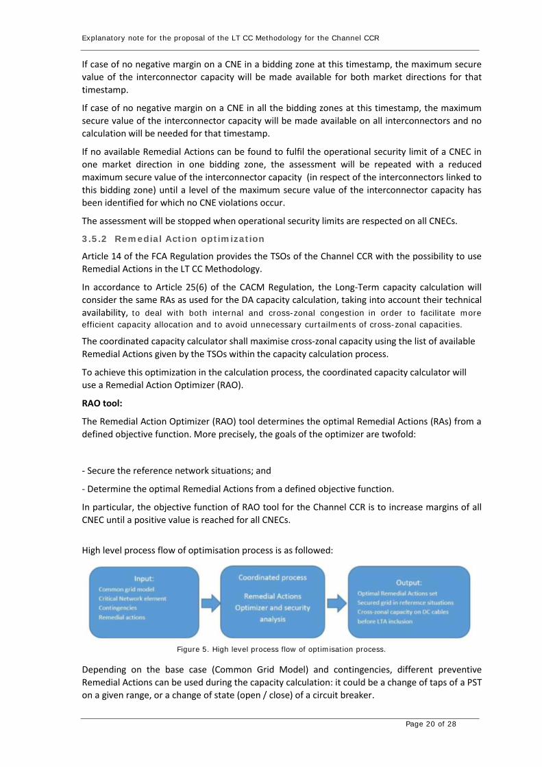
Explanatory note for the proposal of the LT CC Methodology for the Channel CCR
Page 20 of 28
If case of no negative margin on a CNE in a bidding zone at this timestamp, the maximum secure
value of the interconnector capacity will be made available for both market directions for that
timestamp.
If case of no negative margin on a CNE in all the bidding zones at this timestamp, the maximum
secure value of the interconnector capacity will be made available on all interconnectors and no
calculation will be needed for that timestamp.
If no available Remedial Actions can be found to fulfil the operational security limit of a CNEC in
one market direction in one bidding zone, the assessment will be repeated with a reduced
maximum secure value of the interconnector capacity (in respect of the interconnectors linked to
this bidding zone) until a level of the maximum secure value of the interconnector capacity has
been identified for which no CNE violations occur.
The assessment will be stopped when operational security limits are respected on all CNECs.
3.5.2 Remedial Action optimization
Article 14 of the FCA Regulation provides the TSOs of the Channel CCR with the possibility to use
Remedial Actions in the LT CC Methodology.
In accordance to Article 25(6) of the CACM Regulation, the Long-Term capacity calculation will
consider the same RAs as used for the DA capacity calculation, taking into account their technical
availability, to deal with both internal and cross-zonal congestion in order to facilitate more
efficient capacity allocation and to avoid unnecessary curtailments of cross-zonal capacities.
The coordinated capacity calculator shall maximise cross-zonal capacity using the list of available
Remedial Actions given by the TSOs within the capacity calculation process.
To achieve this optimization in the calculation process, the coordinated capacity calculator will
use a Remedial Action Optimizer (RAO).
RAO tool:
The Remedial Action Optimizer (RAO) tool determines the optimal Remedial Actions (RAs) from a
defined objective function. More precisely, the goals of the optimizer are twofold:
- Secure the reference network situations; and
- Determine the optimal Remedial Actions from a defined objective function.
In particular, the objective function of RAO tool for the Channel CCR is to increase margins of all
CNEC until a positive value is reached for all CNECs.
High level process flow of optimisation process is as followed:
Figure 5. High level process flow of optimisation process.
Depending on the base case (Common Grid Model) and contingencies, different preventive
Remedial Actions can be used during the capacity calculation: it could be a change of taps of a PST
on a given range, or a change of state (open / close) of a circuit breaker.

Explanatory note for the proposal of the LT CC Methodology for the Channel CCR
Page 21 of 28
In addition, the remedial actions optimizer (RAO) will take into account ‘remedial action usage
rules’ in the process, i.e. in which case a remedial action can be used.
The ‘remedial action usage rules’ will be defined upfront by TSOs. Concretely, for each Remedial
Action (RA) within its grid, each TSO indicates in its input data for which kind of cases this RA can
be used. For instance:
to solve congestion only on a specific Critical Network Element;
to solve congestion on any Critical Network Elements being part of its Control Area.
Determining the preventive and curative RAs
The inputs of the RA optimisation process are the following data:
- Common grid model: containing the seasonal scenario with the planned outages for this
timestamp;
- List of Critical Network elements and Contingencies;
- List of Remedial Actions available per TSO.
The outputs of the optimisation process are the optimal Remedial Actions set for the considered
timestamp and the computed cross-zonal capacity:
- Preventive Remedial Actions;
- If relevant, Curative Remedial Actions after each Contingency (“C”);
- Cross-zonal capacity on the HVDC interconnectors before LTA or AAC inclusion.
The RAO algorithm explores solutions through a sequential approach made of the following
subproblems: 1. Preventive problem for all CNECs; 2. Curative problem for every Contingency.
On both preventive and curative steps, the available Remedial Actions are tested. The objective
function selects the most efficient ones, which are then implemented. RAs are tested and
implemented through iterations within a search tree by simulating all the implemented
contingencies for preventive RAs. Once the preventive optimization is finished, the set of
preventive actions is fixed and implemented as starting point for all curative optimizations. For
curative RAs, approach is different, and is made contingency per contingency.
Algorithm keeps applying RA until one of the following conditions is fulfilled:
In preventive:
- All preventive Remedial Actions have been tested;
- At a certain step of optimization, no preventive Remedial Actions improve the objective function.
In curative:
- The maximum number of curative actions have been reached;
- At a certain step of optimization, no curative actions improve the objective function.
The output of the RAO is a coordinated set of preventive RAs linked to each Contingency.
3.5.3 Implementation of reduction of the interconnector capacity
In case of a negative margin on CNECs which cannot be solved with available Remedial actions, the
maximum secure value of the interconnector capacity will have to be reduced.

Explanatory note for the proposal of the LT CC Methodology for the Channel CCR
Page 22 of 28
The reduction of the maximum secure value of the interconnector capacity will only concern the
bidding zone where the limiting CNECs are located.
In case several interconnectors are located in the concerned bidding zone, the reduction shall be
applied only to the interconnectors which have an influence on the limiting CNE above the
thresholds defined in Article 8 of the LT CC Methodology and proportionally to their influence.
This is illustrated by the below example, where the capacity over the interconnectors must be
reduced in order to resolve an overload on CNEC X. In this particular case the capacity reduction
over HVDC1 will be twice the reduction of capacity on HVDC2 since the impact of an exchange of
HVDC1 on CNEC X is twice the impact of an exchange of HVDC2 over CNEC X.
Figure 6 reduction of interconnector capacity in case of multiple interconnectors connected to a bidding zone
Specificities of LT time Horizon
The LT capacity for the computed timestamp can differ from the maximum permanent technical
capacity only in case of a specific planned outage of a Critical Network Element with significant
impact on the interconnector exists in one of the bidding zones to which that interconnector is
connected. Each HVDC link will be associated with a set of CNECs that will be monitored in order to
implement reductions of the maximum secure value of the interconnectors capacity.
The NTC values will be computed per interconnector in each bidding zone border per selected
timestamps. In case of a negative margin on the CNECs which cannot be solved with available
Remedial Actions, the congestion is solved by reducing only the maximum secure value of the
interconnector capacity on the interconnectors in the bidding zone border where the limiting CNE
is located. As each interconnector is associated with a set of potential CNECs, the maximum secure
value of the interconnector capacity will be reduced on the interconnectors associated with the
limiting CNECs.
How to implement a shift of import/export
Any shift of the power transfer between two bidding zones shall be realized by adjusting the
generation in each of the bidding zone in line with the GSK of the bidding zone.
Timing & validation
Explanatory note for the proposal of the LT CC Methodology for the Channel CCR
Page 23 of 28
The annual capacity calculation using a Minimum Guaranteed Value must be carried out before the
end of September Y-1 whereas the annual capacity calculation releasing the interconnector MPTC
while using reduction periods must be performed in December Y-1. In respect of the monthly
capacity calculations using reduction periods, they shall be done before the end of the Month M-
2.
The calculations start on D-0 and ends on D+5 for the annual capacity calculation using a Minimum
Guaranteed Value and ends on D+3 for the Monthly capacity calculation. The exact timing of day
“D-0” are the following:
Annual computations: “D-0” = September 15th
Final annual computations: “D-0” = December 1st
Monthly computations: “D-0” = 10th of Month-2
The timings mentioned are a starting assumption and need to be validated during a parallel run.
Mitigating actions
In case no values could be generated during the monthly calculations then the results of the annual
calculation are used.
In case no values could be generated during the annual calculations then the results of the previous
year are used.
3.5.4 NTC calculation process for each timestamp
i. Select and load the representative CGM base case for each selected timestamp;
ii. Apply Generation Shift Keys to each base case in order to reflect each interconnector
operating at
a. Interconnector MPTC in the direction of the synchronous grid of Continental
Europe towards Great Britain and vice versa;
b. Or alternative lower figures used in place of (a) above if an established longer
term restriction is identified based on technical limitations or as the result of a
contract or agreement.
iii. Run contingency analysis on the CGM using the CNEC list provided by the TSOs;
iv. Evaluate results to identify base cases
a. allowing Interconnector MPTC without further actions
b. indicating a potential Interconnector import or export limitation as a result
of a negative margin on a Critical Network Element or operational security
standard violation.
v. For each negative margin on a CNE identified in step iv(b), deploy the list of Remedial
Actions to alleviate this margin of the Critical Network Element.
vi. Evaluate the impact of Remedial Actions. If Remedial Actions can mitigate the negative
margin of the CNE or the operational security standard violation, the interconnector MPTC
can be made available for that scenario timestamp.
vii. If the Remedial Actions used cannot alleviate the CNE violation, the maximum secure value
of the interconnector capacity of the bidding zone where the limiting CNEC(s) is/are located
should be progressively reduced in steps from the starting points set out in Article 18. In
case several interconnectors are located in the concerned bidding zone, the reduction shall
be applied only to the interconnectors which have an influence on the limiting CNE above
the CNE thresholds and proportionally to their influence.

Explanatory note for the proposal of the LT CC Methodology for the Channel CCR
Page 24 of 28
Following each capacity reduction, the contingency analysis should be repeated with the
Remedial Actions already deployed until a level of the maximum secure value of the
interconnector capacity has been identified for which no CNE violations occur. This
establishes the maximum secure value of the interconnector capacity for these scenario
timestamps.
3.6 Long-term cross-zonal capacity process
During the previous step the cNTC is calculated for each selected timestamp delivering a technical
profile that represents the maximum capacity allowed on each HVDC-cable to comply with safety
standards of the network for the concerned time window. With the objective to maximize the
capacity available for the market this technical profile will be given by using the principle of
reduction periods with the exception of the annual capacity calculation using a Minimum
Guaranteed Value.
3.6.1 Annual cross-zonal capacity
Annual capacity
The long-term capacity calculation takes into account planned outages of the relevant CNEs, but
under the SO GL the finalization of the outage planning occurs between 31 October and 30
November of the preceding year. As this is too late to start the allocation of the long-term products
under a scenario-based approach, the first annual NTC-calculation will take place based on a
provisional outage planning before the end of September Y-1 and a second annual NTC calculation
will take place later (in December Y-1) based on the final outage planning. The former generates a
preliminary technical profile and the latter a final technical profile.
Step 1: Minimum Guaranteed Value (MGV)
Following the annual capacity calculation before the end of September Y-1 based on a
provisional outage planning (a high-level knowledge of outage requests for the upcoming
year is needed), a preliminary technical profile will be calculated based on the selected
timestamps. The NTC (Net Transfer Capacity) given will equal the minimum value of the
technical profile (Cfr. Figure 7) with the exception of the planned outage of the HVDC-
interconnector itself (which could potentially lead to 0MW capacity for LT allocation
depending on the technical construction of the HVDC).
Figure 7. Example of Minimum Guaranteed Value
This Minimum Guaranteed Value approach offers margins towards changes in onshore
TSOs outage planning (the outage can be shifted in time without the need for curtailment).

Explanatory note for the proposal of the LT CC Methodology for the Channel CCR
Page 25 of 28
The MGV approach allows to allocate capacity prior to the finalization of the outage
planning while taking into account safety standards. The planned outage of the HVDC-
interconnector itself will be immediately considered as reduction period and will not part
of the MGV approach.
Step 2: Reduction Period
After finalization of the outage planning on the CNEs under SO GL (at the latest before 1
December of the preceding year) a final technical profile is defined based on the selected
timestamps as outages are considered as firm. Based on the preliminary profile additional
calculations are performed if required. The NTC given will be equal to the technical profile
calculated by using the principle of reduction periods (Cfr. Figure 8). The exact start and
end dates of the reduction period must be provided before the allocation stage.
Figure 8. Example of reduction periods in LT products
This approach releases the remaining capacity available during periods with no planned outages.
In case the planned outage on a CNE is reduced or cancelled, the updated reduction period has to
be communicated as soon as possible.
3.6.2 Monthly cross-zonal capacity
Based on the latest information on the outages planned of the Critical Network elements, available
in the OPC database, an updated technical profile will be calculated based on the selected
timestamps. The NTC given to the market will be equal to the updated technical profile calculated
by using the principle of reduction periods (Cfr. Figure 8) taking into account LTA. In case the
planned outage on a CNE is reduced or cancelled, the updated reduction period has to be
communicated as soon as possible.
3.6.3 Other long-term cross-zonal capacity
No updated technical profile will be calculated, instead the most recent available technical profile
is used. For products with a duration greater than one month, the capacity will be derived from
annual capacity calculations. For products with a duration equal to or less than one month, the
capacity will be derived from monthly capacity calculations.
Timing & validation:
Preliminary scenario based annual cross-zonal capacity using a Minimum Guaranteed Value
With D+0 fixed on September 15th of the preceding year, or the first Monday after in case of a
weekend, the preliminary annual calculations start on D+0 and are finished by D+5 expressed in

Explanatory note for the proposal of the LT CC Methodology for the Channel CCR
Page 26 of 28
working days. The validation of the preliminary technical profile ends by D+10 giving a period of 5
working days for initial calculations and 5 working days for iterations and validation. The resulting
MGV is published on D+10.
Final scenario based annual cross-zonal capacity using reduction periods
With D+0 fixed on December 1st of the preceding year (immediately after the finalization of the
outage planning according SO GL), or the first Monday after in case of a weekend, each TSO
indicates the latest on D+2 to the CCC if new NTC calculation is required. The CCC recomputes the
requested timestamps before D+5. On D+5 the final technical profile is validated by the TSOs and
the remaining capacity is released.
Monthly cross-zonal capacity
With D+0 fixed on the 10th of Month-2, or the first Monday after in case of a weekend, the monthly
calculations start on D+0 and are finished by D+3. The validation of the updated technical profile
ends by D+8 giving a period of 5 working days for iterations on the cNTC calculation and validations.
The resulting NTCs are released on D+8.
The timings mentioned are a starting assumption and need to be validated during a parallel run.
Mitigating Actions
In case no values could be generated during the monthly calculations then the results of the annual
calculation are used.
In case no values could be generated during the annual calculations then the results of the previous
year are used.
3.7 Step 4: cross-zonal validation
As mentioned in the paragraph of the long-term cross-zonal capacity process, all TSOs have the
responsibility to validate the capacities proposed by the CCC and may locally re-assess the
computed NTCs on the interconnector. This re-assessment may be necessary to prevent any risk
due to possible unforeseen changes in grid situations which have occurred during the qualification
phase such as
a. Forced outage on one interconnector or one element defined as CNE or Contingency;
b. A mistake in input data, that leads to an incorrect cross-zonal capacity;
c. Any other criteria that the TSO shall have previously defined, let agreed by its NRA and
published in its website before its application.
In the case of such unforeseen changes and if a TSO is detecting a constraint, the TSO may reduce
the proposed NTCs.
The reduction of the proposed NTCs shall be monitored, based at minimum on an identification of
the limiting CNEC and the explanation of the unforeseen event causing the NTC reduction. The
output of this process is the amended NTC which is considered as the final NTC.
Explanatory note for the proposal of the LT CC Methodology for the Channel CCR
Page 27 of 28
3.8 Fallback procedure
In accordance with Article 42 of the FCA Regulation, in the event that the coordinated capacity
calculator is unable to produce results, the default fallback procedure shall be the postponement
of the forward capacity allocation.
In case the postponement of the forward capacity allocation is not possible, or the new deadline
has been reached and no results are available, the TSOs of the Channel CCR foresees the following
fallback process:
- For the annual capacity allocation, the TSOs will use as a starting point cross-zonal long-
term capacity calculated by the CCC for the equivalent planned outages for the previous
year. The TSOs of the Channel CCR will bilaterally validate these NTC values and then these
values will be validated in a coordination meeting of the TSOs of the Channel CCR.
- For the monthly allocation, the TSOs of the Channel CCR will use as a starting point cross-
zonal long-term capacity calculated by the coordinated capacity calculator during the
annual process for this month. The TSOs of the Channel CCR will bilaterally validate these
NTC values and then these values will be validated in a coordination meeting of the TSOs
of the Channel CCR.
Explanatory note for the proposal of the LT CC Methodology for the Channel CCR
Page 28 of 28
4 Criteria for an operational process
Performance of the N-1 security assessment of the maximum import/export
NTCs computation is based on an N-1 security assessment of both import and export market
directions for the Channel CCR for each timestamp. The capacity calculation process for the Channel
CCR is based on an AC loadflow computation using several input data from TSOs to be processed
by the CCC. Following the defined methodology, 4 grid situations (import/ export cases on UK side
and on continental Europe side) have to be computed for each timestamp. In addition, the
computation time will be mostly influenced by, on one hand, the content of input data and in
particular the number of outages, amount and kind of Remedial Actions and also the base case
situation of the grid which could vary from non-congested cases to highly congested cases that will
have to be managed by the CCC operator, and on the other hand by the IT infrastructure (machine
speed and memory) will also influence the possibilities to run parallel computations in a dedicated
short period of time. Moreover, the use of the new CGMES format containing much more
information in the grid models will have an impact on the memory of the used machine. For the
Channel project, real simulations of the calculation process with industrialized solution, which have
not been started yet, will give a better view on the possibilities to optimize the computation time.
Considering the time available for LT CC process the feasible number of assessed TS will be
confirmed.
Taking into account the abilities of the tools and their foreseen development, the CCC shall
maximize the number of assessed representative timestamps.
During the implementation phase and especially during internal parallel run, TSOs and CCC will
consider the maximum number of assessed representative timestamps. Considering the time
available to perform the process in the annual and monthly time horizon, the number of assessed
timestamps may be different in each case.

Page 1 of 6
Consultation Report for the Channel TSOs proposal of a common capacity calculation methodology for
the long-term time frames
January 21st, 2020
Disclamer
This assessment of stakeholders’ comments is submitted by all TSOs of the Channel Region to all
NRAs of the Channel Region for information and clarification purposes only accompanying the
proposal for common capacity calculation methodology for the long-term market timeframe in
accordance with Article 10 of Commission Regulation (EU) 2019/1719 of 26 September 2016.

Page 2 of 6
Table of Contents 1. Assessment of the Stakeholder’s comment .............................................................................................. 2
1.1 General consultation responses ............................................................................................................ 2
1.2 Consultation responses per article........................................................................................................ 3
1. Assessment of the Stakeholder’s comment
Common main themes grouped together as follows:
1. Provision of 35%
a. Justification for choice of 35% cap.
b. More clarity on value being fixed as max./min threshold.
c. Why restricted to 35% if calculations would allow a higher fraction?
2. Approaches
a. Which approach is most optimal in achieving 35%?
b. Working examples of each approach to be provided.
c. Arbitrariness of 50% reduction (app 1), P10 (app 2), 35th percentile (app 3).
d. Unclear why margin per Art. 23.1(c) added (app 1).
e. Inclusion/exclusion of effects of RAs/countertrading.
f. Is countertrading before or after DA market coupling?
3. Validation
a. Rationale behind reductions to proposed value.
b. Arbitrariness of “very high risk threshold”.
c. Principle of reduction periods and their application.
d. CNEs per Art. 6(4) not part of statistical approach.
4. General Context
a. If this behaviour triggers increase in dispatching actions taken by TSOs, it risks non-compliance with
clean energy policy.
b. Will TSOs in Channel CCR provide an economic assessment for the chosen approach once agreed
and submitted to NRAs?
1.1 General consultation responses
This consultation report is provided to the Channel National Regulatory Authorities and has been prepared by
all Channel TSOs. Channel TSOs aim at providing more clarity on the Channel Long Term Capacity Calculation to
the market Parties.
Channel TSOs acknowledge that providing an explanatory note to the Market parties would have been useful.
An explanatory note is in the process of being prepared which will provide further relevant information on the
principles underpinning the long-term capacity calculation methodology as well as elaborating on the content
and text of the proposal itself.
One main point which was not clear for the market parties is why the capacity is capped to 35% in February.
Market parties would like maximum capacity earlier in the year for their hedging strategy. This is clear; however,
from a TSOs perspective, we believe that offering at most 35% of the MPTC in February Y-1 is already a big step
for the market parties as in all the other capacity calculation regions in Europe, there is no calculation before
end of the year Y-1 and so the possibility for hedging is more restricted.

Page 3 of 6
Another point which might be confusing, is that the auctions need the capacity calculation results as an input.
But once these results are available, the Interconnectors are free to schedule the auctions all along the year (and
not necessary only in February, September and December) as long as the splitting rules methodology is
respected by all parties.
Market Parties have been requested to deliver their view on the topic of RoCoF, Channel TSOs have delivered
to the Channel NRAs two different documents concerning RoCoF explaining the two different views.
1.2 Consultation responses per article
Article 1: Subject matter and scope
“Non-standard” products (e.g. seasonal, quarterly, weekly etc.) are also accommodated in the
LT CCM and referenced under Article 3.4
Article 2: Definitions and interpretation
No comments received related to this article.
Article 3: Capacity calculation approach
A clearer differentiation of the statistical and scenario-based capacity calculation approaches
(accompanied by additional text elaborating on their respective timings) is provided in this Article
following this feedback. The document justifying the use of a statistical-based approach in accordance
with Article 10.4(b) of the FCA Regulation will be prepared and submitted in the Explanatory Note
following the received guidance of the Channel NRAs
Article 4: General principles
This refers to the statistical-based approach where the February Y-1 timeframe for performing
the capacity calculation is proposed and as such broadly reflects the recognition that annual capacity
being made available to the market early in the year prior to delivery supports the objective described
in Article 3(a) of the FCA Regulation.
Article 5: Methodology for the statistical long-term capacity calculations
No comments received related to this article.
Article 6: Validation
No comments received related to this article.
Article 7: General principles for long-term cross-zonal capacity calculations
No comments received related to this article.
Article 8: Critical Network Element and Contingency (CNEC) methodology
The chosen wording in Articles 8.5 and 8.6 is the same as that used in Articles 7.5 and 7.6 of
the DA/ID capacity calculation methodology as are the selection criteria themselves. Article 7.4 also
makes it a mandatory task for each onshore TSO to publish on its website the list of grid elements
identified as a result of applying such selection criteria.

Page 4 of 6
Article 9: Reliability margin methodology
Some market parties consider that using for the LT CCM the same FRM (Flow Reliability
Margin) as in the day-ahead and intraday CCM is not adequate since uncertainties are necessarily
higher in the LT timeframes.
Channel TSOs understand the reasoning of the market parties. However, the uncertainties
between LT CCM & DA/ID CCM will be covered by the choice of scenarios. So Channel TSOs believe
this uncertainty is acceptable and covered in the LT CCM methodology.
Article 10: Methodology for operation security limits
No comments received related to this article.
Article 11: Generation shift keys methodology
No comments received related to this article.
Article 12: Methodology for Remedial Actions in capacity calculation
No comments received related to this article.
Article 13: Scenarios definition methodology
No comments received related to this article.
Article 14: Timestamp selection
Channel TSOs received the following proposal: “Rather than selecting the timestamp via the
number of simultaneous outages, why not considering the gravity of the outage directly via the
PTDFs?”
We believe this proposal is highly interesting, make sense and would be an improvement of
the methodology. However, due to the already limited list of CNECs following the usage of a PTDF
threshold, Channel TSOs believe that the impact of such an improvement will be very limited.
Article 15: Provision of the inputs for the long-term capacity calculations
No comments received related to this article.
Article 16: Long-term capacity calculations
In theory, the simultaneous import/export aim at assessing the maximum transfer of power
on each direction between GB and Continental Europe that will be possible to reach simultaneously
without endangering the security of the system.
So from a GB perspective, it is to maximize the import/export flow from continental Europe
to GB.
On the formulation, Channel TSOs will work to make the articulation between Articles 16 &
20 clearer and more precise (and across all the document as a general statement).
Article 17: Coordinated Net Transmission Capacity process

Page 5 of 6
In article 17.2 the CCC will just do a contingency analysis to see if the MPTC for each
interconnector can be reached or not without limitation or further actions. In order to make it clearer
the sentence “With the objective to maximize cross zonal capacity” will be deleted from the final
methodology as this paragraph refers to a contingency analysis only without the use of remedial
actions.
Only in case the check is negative and the capacity could potentially be limited then the CC
will apply the remedial actions as described in article 17.3.
Article 18: Implementation of reduction of import/export
Some Market parties don’t understand why Channel TSO will only consider the BZ where the CNE is located for the max import/export. Channel TSOs will update the article to make it clear.
Article 19: Implementation of shift of import/export
No comments received related to this article.
Article 20: N-1 security assessment of maximum import/export for each timestamp of the
calculation
No comments received related to this article.
Article 21: Calculation consistency
No comments received related to this article.
Article 22: Cross-zonal capacity validation methodology
In case of LT capacity already auctioned, and if a TSO sees the need to re-assess this capacity, the reasons behind this re-assessment would be transparent as they should follow only the points described in article 22.2. This Article 22 is not to be confused with the general transparency requirements as stipulated under Article 24 of the proposal
A point which need to be clear is that unless in case of real issue for security operation, the
final NTC provided by the LT capacity Calculation to the market would not be lower than the capacity already sold by the Interconnectors (in accordance to Article 21.2). Article 23: Fall-back procedures for annual and monthly capacity calculations
No comments received related to this article.
Article 24: Publication of information
No comments received related to this article.
Article 25: Implementation of the LT CC Methodology
No comments received related to this article.
Article 26: Implementation of new interconnectors
No comments received related to this article.

Page 6 of 6
Article 27: Language
No comments received related to this article.