james webb space telescope (jwst) - nasa · pdf filejames webb space telescope (jwst) rick...
TRANSCRIPT

1
James Webb Space Telescope (JWST)
Rick Howard
JWST Program Director
NAC Technology and Innovation Committee
March 6, 2012

JWST – the next great observatory
� JWST is the scientific and technological successor to HST� HST has looked deeper into the Universe that any telescope. It took HST more than three
continuous days to do so. JWST will do that in less than an hour
� JWST is:� More than 6 times the collecting area of HST
� 100 times more sensitive than HST, over 1000 times more than Spitzer
� Operated at 40K (~ - 400°F )
� Operated in deep space, about 1,000,000 miles from Earth (4X further than the
2
� Operated in deep space, about 1,000,000 miles from Earth (4X further than the Moon)
� Cooled by a deployed sunshade the size of a tennis court
� Half the mass of HST

� Segmented Beryllium Primary Mirror
� areal density 3 times less than HST
� Technologies for JWST mirror manufacturing and polishing broadly applicable for future space telescopes
� Must fold up to fit inside rocket fairing, breaking the limitation on mirror diameter
� Composite structure to hold mirrors and instruments
� Behavior must be known to <40 nanometers (~1/10,000 of a human hair)
� Must maintain this stability while being cooled over 400 degrees
� Cryogenic Application Specific Integrated Circuit ( ASIC)
� JWST ASIC already flying in space: Installed on Hubble Servicing Mission 4 to repair the failed Advanced Camera for Surveys (ACS) instrument
� Micro -Shutters
3
� Micro -Shutters
� ~100,000 computer controlled shutters, each the width of a human hair
� First Mirco-ElectroMechanical (MEMS) devise for science to be flown in space
� Early research on MEMs devised for JWST helped develop analogous instrument for ground-based telescopes
� Sunshield Membranes
� Lightweight deployable sunshield the size of a tennis court to passively cool JWST telescope and instruments
� 5 thin separated membrane layers (each less than half the thickness of a piece of paper)
� Providing a 500 F temperature difference (equivalent SPF of 1,000,000)
� Advanced Near Infrared Detectors
� Advanced Mid-Infrared Detectors
� Cryo-cooler for Mid-Infrared Instrument
� Mirror Phasing and Control Software
� Heat Switches

TECHNOLOGICAL ADVANCES
Mirror Support StructureStructures hold mirrors and science instruments super stable, behavior must be known to ~38 nanometers (~1/10,000th
of a human hair!)
Segmented Beryllium Mirror
Mirrors so smooth that if “stretched” to the size of
the continental US largest deviation from perfection
would be ~2 inches in height.
Advanced Near Infrared detectors
Advanced Mid-Infrared detectors
4
Sunshield Membrane
5 thin membranes (each less than half the thickness of a piece of paper) protect the side in the extreme of cold space from the warm sunlit side [Equivalent Sun Protection Factor (SPF) of 1,000,000]
Mirror phasing and control
18 mirror segments
computer controlled to
operate as one mirror in
space
Microshutters
~100,000 computer controlled shutters,
the width of a human hair enable optimal
science return
Cryogenic ASICs
Ultra-sensitive detectors on JWST
could see a single candle on the
Moon from 1 million km.
Green borders denote
actual spaceflight
hardware, red borders
are test equipment

The Final Acceptance Test Completes a Decade plusDevelopment Effort to Make JWST Mirrors
200019981996 200620042002 20102008 2012 2014
Onset of James Webb Space Telescope
Advanced Mirror System Demonstrator (AMSD)Collaboration among 3 government agencies15Kg/m2, 1.2M diameter segments
AMSD Phase 1:8 Mirror Designs
AMSD Phase 2:3 mirrors developed
MediumAuthority
Glass (ULE)
Low Authority Beryllium
AMSD Phase 3/Six Sigma StudyBe manuf. and process improvements
OTE Optics Review
Technology Readiness Level-6 Demonstrated:All key requirements and environments demonstrated
Engineering Design Unit .
5
Low Areal Density Mirrors Identified as Key Enabling Technology for 25 Square Meter Space Telescope
Subscale Beryllium Mirror Demonstrator (SBMD):.5 meter diameter,
Review (OOR):Beryllium Selected
Machining Facility Complete
Engineering Design Unit .
PM Manufacturing of 18 segments
Cryo Testing
PolishingFacility Complete
Primary Mirror Segment Assemblies Complete

Coated Primary Mirror Segment Assembly
6

Primary Mirror Assembly
7

8

99
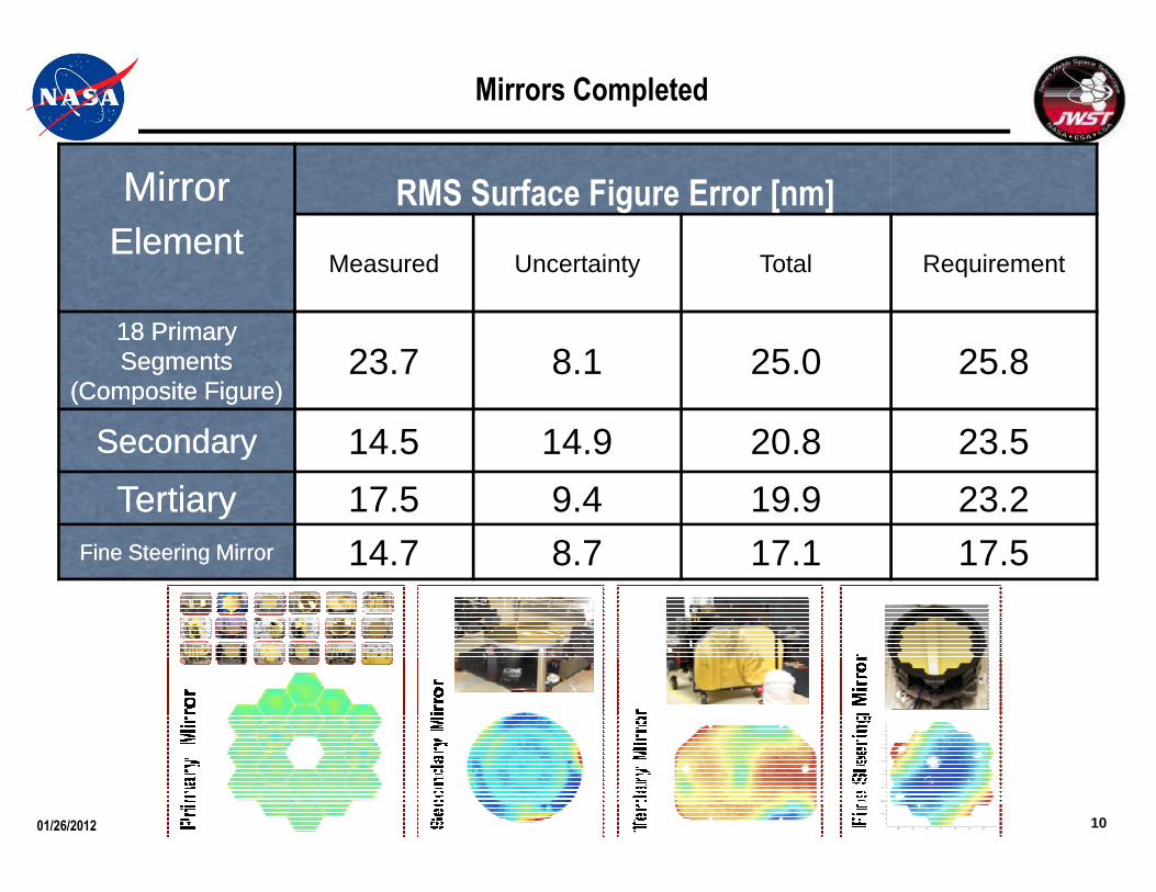
MirrorMirrorElementElement
Measured Uncertainty Total Requirement
18 Primary 18 Primary Segments Segments
(Composite Figure)(Composite Figure)23.7 8.1 25.0 25.8
SecondarySecondary 14.5 14.9 20.8 23.5
RMS Surface Figure Error [nm]
Mirrors Completed
10
SecondarySecondary 14.5 14.9 20.8 23.5
TertiaryTertiary 17.5 9.4 19.9 23.2Fine Steering MirrorFine Steering Mirror 14.7 8.7 17.1 17.5
01/26/2012

Completed Mirrors in Storage
11

� PMBSS Center Section fabrication and assembly
� Piece part fabrication - 100% complete
� Assembly bonding continuing @ ~87% complete
FlightFlight Backplane Bonding StatusBackplane Bonding Status
Status as Status as of: 11/30/2011of: 11/30/2011
12
Center Section Assembly Locations
PMBSS Center Section Assembly - in process
: Not Assembled: Assembled: Recently assembled since last PMR

Sunshield Template Membrane Work On-Going
� Template Layer 3 build and testing complete . Packed for shipping to NGAS
� Shape measurements show RMS error of 0.71 in. versus requirement of 0.75 in.
Layer 3
13Preliminary Template Layer 3 Scan
� Template Layer 5 seamed and catenaries/fill regions installed. Currently getting edge features and grommets installed
� Template Layer 4 fully seamed
Layer 5
01/19/2012

MIRI Cryo Cooler Overview
�Provides the needed active cooling to ~6K for the MIRI detectors and Optical Assembly
� The first long life, 6K mechanical cooler
� Implemented as hybrid multi-stage mechanical Pulse-Tube Joule-Thomson (JT) Cooler
14
Thomson (JT) Cooler
� Challenging architecture with the 6K load several (~10) meters from the compressors

� Flight detector testing shows a degradation in pixe l operability� Impacts NIRCam, NIRSpec, and FGS
� Detector FRB complete� Found that detector degradation is caused by a design flaw which impacted its
performance� The Detector FRB found that the detector degradation is caused by a design flaw in the barrier layer of the
pixel interconnect structure, degrading its performance
� The flawed barrier layer design makes the detectors vulnerable to migration of indium from the indium bump interconnect into the detector structure
Technical Issue – Detector Degradation
15
• Determined manufacturing and/or post-manufacture handling process changes are appropriate
• Defined tests needed to screen-out degradation prone parts and insure the continued integrity of flight part
• Fabrication of next generation detectors for testing (Jan-April) is underway
� Decision for the detector swap will be in March 201 2

� ETU Detector Status� Teledyne has recently completed testing Short Wave (SW) detectors fabricated
for their ground-based astronomy customers.• Several of these SCAs were fabricated using new bake-stable process which will
correct degradation issue seen on JWST detectors– Are similar to the JWST SW parts, thereby providing the first performance test of JWST-like
parts using the new process• Test results show the new process does not appear to have any adverse effect on
science performance
Technical Issue – Detector Degradation
16
� Still on schedule to receive the first Mid-Wave and SW detectors in early January• Total of 22 SCAs to be delivered (Jan-April) for testing
– Testing starts at Teledyne in Jan, then proceeds to University of Arizona and the GSFC Detector Characterization Lab in Feb.

New Optical Measurement Devices
� The need to accurately measure the shape of the JWST mirrors required significant improvements in wavefront sensing technology (Scanning Shack-Hartman Sensor)
� Has enabled a number of improvements in measurement technology for measurement of human eyes, diagnosis of ocular diseases and potentially improved surgery
• Eye doctors can now get much more detailed information about the shape of your eye in seconds rather than hours
JWST Tech Spin Offs
17
• Four patents have been issues as a result of these innovations
Cryogenic ASIC
� JWST developed a low-noise, cryogenic ASIC to convert the analog signals from the near-IR detectors to digital
� Same design used on ASIC now being used in the Advanced Camera for Surveys which was repaired during the HST SM-4 servicing mission
� “future heritage”

Laser Interferometers utilizing High Speed Optical Sensors
� JWST needed to make measurements of mirrors and composite structures with nanometer precision in cryogenic vacuum chambers (with vibrations from pumping systems a constant problem)
� JWST provided 4D its first commercial contract to develop the PhaseCam interferometer system
JWST Tech Spin Offs
18
system
� 4D Technology Corp has developed several new types of high-speed test devices that utilize pulsed lasers that essentially freeze out the effects of vibration
� 4D has gone on to generate over $30 M in revenue from a wide range of applications in astronomy, aerospace, semiconductor and medical industries based on the technologies developed for JWST

Implementing the New Baseline
� Completed the replan (9/23/2011) with an October 20 18 launch date
� Plan has adequate cost and schedule reserves consistent with ICRP recommendation
� Additional $44M in FY11 was approved by Congress
� FY12 budget approved by Congress with full funding for JWST
� FY13 PBR fully funds the new baseline
� Recent Accomplishments
� All flight optics have been cryo tested and meet requirements
� Completed the Aft Optic System integration and alignment
� Primary Mirror Backup Support Structure center section nearly complete (94% of bonding is complete)
19
� Sunshield full scale Engineering Development Unit for layer #3 testing completed with good results
� Instrument deliveries to GSFC begin in Spring 2012
� Brought back in work with additional FY11 funding a nd FY12 budget
� Accelerated: Backplane Support Frame (BSF) by 4 months, completion of PMBSS by 4 months, start of Wings by 18 months, end of Flight Optics Integration by 4 months
� Still have 13 month of funded schedule reserve on critical path
� Instrument deliveries slipped moving ISIM delivery to OTIS by 5 months (31 months to 26 months)
� Even with Detector change out, still have 11 months slack for ISIM delivery to OTIS
� ETUs for NIRSpec and NIRCam will be used in ISIM Cryo Test 1(all have flight hardware for CT 2+3)
JWST made great progress in FY11 and continues to d o so in FY12, achievingmilestones within cost and schedule and executing t o the new baseline

Hardware Fabrication Completion Percentages
Primary Mirror Segments
100%
Science Instrument Module
& Science Instruments
Primary Mirror Support Structure
95%
100%
Aft Optics System
20
& Science Instruments
90%
Secondary Supports
80%
Spacecraft Bus
25%
Sunshield Membranes
40%
As of 1/13/2012
Green borders denote
actual spaceflight
hardware images, red
borders are test
equipment
100%
Secondary Mirror

2010 2011 2012 2013 2014 2015 2016 2017 2018 2019
FY10 FY11 FY12 FY13 FY14 FY15 FY16 FY17 FY18 FY19
2 3 4 1 2 3 4 1 2 3 4 1 2 3 4 1 2 3 4 1 2 3 4 1 2 3 4 1 2 3 4 1 2 3 4 1 2 3
JWST Overview
Schedule
Major Mission Milestones
Integration & Test
OTE
Primary Mirrors
Flight Structure (PMBSS)
Sunshield
4
CDR
3
TRR
4
MOR
9
SIR
12
KDP-D
8
PSR
9
FRR/KDP-IV
10
LRD
4
ORR
4
SC Panel Integ
7
CCA,PropInteg
8
SS Integ
10
SC Test
7 9
SC/OTE I&T
5 9 10
Launch Site
2
JSC CH AGSE Install
4
PF Install/ Test
11
OTIS I&T
7 7
8
Start EDU3rd Cryo Test
4
Del PFPMSA
9
1st Batch
2
Last Batch
10
PF SMSS/StrutInteg
8 11
PF Optics Integ
2
Flt OpticsInteg
7 12 4
11
BSF Assy Start
3
Wing Assy StartFlightPMBSS
2
OTE StructureAssy/Test
6TemplateMembrane Fab
10
Flt Membrane Fab
4
Flt MembraneMRR
4Astro Tube Fab GSE Design/Fab
4
2
2
3
41
3 24
Master Schedule
21
Spacecraft
ISIM I &T
NIRSpec
MIRI
NIRCam
FGS
Cryo Cooler System
Ground Segment
Launch Segment
10 4 4
2
Astro Tube Fab
9 11
GSE Design/Fab
6
12
Structure Mfg & Test
12 4 8
Integ Skeleton& Membrane
2
6
CDR
11
SC Panel &SC Structure
3
SC Structure
7
Start I&T
12
PER
5
Del Flt ISIMto OTIS
1
ETU Del
8
Flt Del
3
STM Del
4
Flt Del
5
ETU Del
8
Flt Del
5
ETU Del
6
Flt Del
4
Fit CheckCHA
8
Flt CHA
10
ETUCCES/CELS
10
CCA Mock-up
2
Flt CTA
1
FltCCA/CCE
7
Flt CCA/CCE (Spares)
4
CCTS Build 2.3
1
CCTS Build 2.4
9
CCTS Build 2.5
10
Begin End-to-EndGrnd/Flt Seg Testing
10 4
Comissioning
8
Safety Submittal 2
11
Ariane Adapter
5
Safety Submittal 3
6
RAMF
7
DCI Release 2 (Final)
12
LV Lift Performance Verified
10
Flight Adapter Fit Check
4
CLA6
7 3
Flight Adapter &Shogun Equip
9
CLA7
12 4
CLA8
7 9
LV Readiness Review (RAV)
26
4
4
13 Months of Funded Critical Path Slack 6 Months at Observatory I&T 3 Months at OTE I&T 4 Months of Embeded Slack in OTE Activities
4
4
2
REV -
After testing of replacement detectors, the ISIM flow will be updated to show the detector change-out strategy.

Work-To-Go (FY12 to Launch and Commissioning)
22
% work on this element to-goRelative proportion of project funding to-go

Optical telescope element Simulator (OSIM) IntegrationOn Track for Cryo Verification mid-April 2012
Status as of:Status as of: 1/31/121/31/12
ISIM
2323

Telescope Assembly Ground Support Equipment
Hardware has been installed at GSFC
approximately 8 weeks ahead of
24
approximately 8 weeks ahead of
schedule
Landing a mirror onto backplane
simulator
Ambient Optical Alignment Stand Complete
01/19/2012

OTE Testing – Chamber A at JSC
25Will be the largest cryo vacuum test chamber in the world
Notice people for scale

Pressure Tight Enclosure
(PTE)
Multi Wavelength
Interferometer (MWIF)
Displacement Measuring
Interferometers (DMIs)
Hexapod Actuator
Center of Telescope Curvature Optical Test EquipmentCenter of Telescope Curvature Optical Test Equipment
26
Hologram
Null Assembly
Beam Splitter and
CASS Camera

BACKUP
27
BACKUP

James Webb Space Telescope (JWST) goes beyond Hubble and other space telescopes by seeing things that they cannot see…
• How did the universe make galaxies?• Are there other planets that can support life?• How are stars made?
James Webb Space Telescope (JWST) goes beyond Hubble and other space telescopes by seeing things that they cannot see…
• How did the universe make galaxies?• Are there other planets that can support life?• How are stars made?
28
JWST is about beginnings: the beginning of galaxies, the beginning of stars, the beginning of planets and life.
JWST is about beginnings: the beginning of galaxies, the beginning of stars, the beginning of planets and life.
First Light Planets and the Origins of Life
The Assembly of Galaxies Birth of Stars and Planets

29

Deployed Configuration
6.600 m
6.100 m
30
• Optical Telescope Element (OTE) diffraction limited at 2 micron wavelength.
– 25 m2 , 6.35 m average diameter aperture.
– Instantaneous Field of View (FOV) ~ 9’ X 18’.
– Deployable Primary Mirror (PM) and Secondary Mirror (SM).
– 18 Segment PM with 7 Degree of Freedom (DOF) adjustability on each.
• Integrated Science Instrument Module (ISIM) containing near and mid infrared cryogenic science instruments
– The Near-infrared camera functions as the on-board wavefront sensor for initial OTE alignment and phasing and periodic maintenance.
• Deployable sunshield for passive cooling of OTE and ISIM.
• Mass: < 6530 kg .
• Power Generation: 2000 Watts Solar Array.
• Data Capabilities: 471 Gbits on-board storage, 229 Gbits/day science data.
• Science Data Downlink: 32 Mbps.
• Life: 5 years [Designed for 11 years (goal) of operation]. 30
21.197 m
10.661 m
Stowed Configuration
4.472 m
14.625 m