jamalzadeh-molecular dynamic simulation for studying...
TRANSCRIPT
2nd National Iranian Conference on Gas Hydrate (NICGH) Semnan University
Molecular Dynamic Simulation for Studying Stability of Structure I CO2 Clathrate-Hydrate
Mohammad Gharebeiglou, Zeinab Jamalzadeh, Hamid Erfan-Niya *
Authors’ Addresses:Department of Chemical Engineering, University of Tabriz, Tabriz, Iran
*Corresponding Author’s E-mail: [email protected]
Abstract Environmentally, CO2 removal in form of CO2 hydrate in the ocean is one possibility of reducing the atmospheric concentrations of this greenhouse gas and assist in diminishing global warming. Considering the importance of CO2 hydrates, this paper focuses on molecular dynamics (MD) simulations of structure I CO2 hydrate. The goal is to study the stability of the clathrate at different temperatures. For achieving this purpose, energetic and structural properties are calculated. Equilibrium MD simulations are carried out to study the properties of fully occupied CO2 clathrate-hydrate at 260, 270, 280, and 290 K using CVFF force field. A mixture of water and CO2 placed in a cubic cell is used as a model system to simulate the CO2 clathrate hydrate at 5 MPa during total simulation time of 200 ps. The cell parameters, stablization energies as well as radial distribution functions are computed. The obtained results at different temperatures indicate the hydrate stablility at low temperatures up to 280 K. Moreover, stablization energy outcomes reveals that CO2 hydrate is more stable than the empty clathrate.
Keywords: Molecular dynamic simulation, CO2 hydrate, Thermodynamic properties Research Highlights
• CO2 removal as a greenhouse gas in form of gas hydrates is studied in curent research. • In order to study the structure I CO2 hydrate MD simulations are developed. • The static structure properties as well as energies, and thermodynamic properties are
calculated.

MD Simulation for Studying Stability……
1.Introduction Gas hydrates (or clathrate hydrates) are ice-like crystalline molecular complexes composed
of water and gas in which solid lattices of water molecules trap ‘guest’ gas molecules in a cage-like structure, or clathrate [1,2]. They are formed when water and gas are combined at low temperature and generally high pressure (e.g. temperatures below 25◦C and pressures greater than 1.5 MPa for natural gas hydrates) [3]. The water molecules in gas hydrates are linked to each other through hydrogen bonds to form a host lattice with polyhedral cavities that are large enough for small gas molecules such as methane, ethane, propane, carbon dioxide, and hydrogen sulphide to occupy [4]. When gas hydrates dissociate, the crystalline lattice breaks down into liquid water and the gas is released [1,2]. The common naturally occurring gas hydrates are known in three structural forms of structure I and structure II with cubic symmetry [5] and structure H with hexagonal symmetry [2]; However, the current study is based only on structure I hydrates. Structure I hydrate has two types of cavity: a small pentagonal dodecahedral cavity consisting of 12 pentagonal rings of water (20 water molecules) and a large tetrakaidecahedral cavity consisting of 12 pentagonal and two hexagonal rings of water (24 water molecules) [3]. Commonly cited structural details are given in Table 1. In the last decades, hydrates have been studied as a possible energy resource, for storage of natural gas, for purification of saltwater, and as a means for storing CO2 [4]. Natural gas hydrates are considered as potential sources of energy as well as possible agents of global climate change [6]. For instance, at conditions of standard temperature and pressure (STP), one volume of saturated methane hydrate (Structure-I) will contain as much as 189 volumes of methane gas; and because of this large gas-storage capacity, gas hydrate are thought to become a new energy source [7]. On the other hand, deep-sea disposal of CO2, as a greenhouse gas by product of energy production, is certain to lead to CO2 hydrate formation [6]. CO2 emitted from burning fossil fuels is believed to be a major contributor to the amount of CO2 levels in the atmosphere. CO2 hydrate is denser than seawater, and therefore CO2 hydrate deposited in the ocean will sink to the sea-bed as long as the disposal site is within the hydrate formation envelope. Hence, the use of hydrates for CO2 storage is aimed at reducing CO2 emissions to the atmosphere, where it may contribute to global warming. Recently, the role of hydrates in the plugging of gas transmission lines has received renewed attention [8] because of the necessity for under sea transportation of gas and oil containing water.
Table 1. Hydrate Structure for Undistorted Lattice [5,9]
Property Structure I Structure II Structure H Symmetry cubic cubic hexagonal cell constant (Å) 12.0 17.3 small cavity 512 512 435663512 diameter (Å) 7.88 7.82 large cavity 51262 512 64 51268 diameter (Å) 8.60 9.46 structural formula 2(512)6(51262)46H2O 16(512)8(51264)136H2O 3(512)2(435663)1(51268)34H2O
Gas hydrate thermodynamics are important in all these applications and have been studied extensively to predict the equilibrium pressure-temperature conditions for hydrate stability.
2nd National Iranian Conference on Gas Hydrate (NICGH) Semnan University
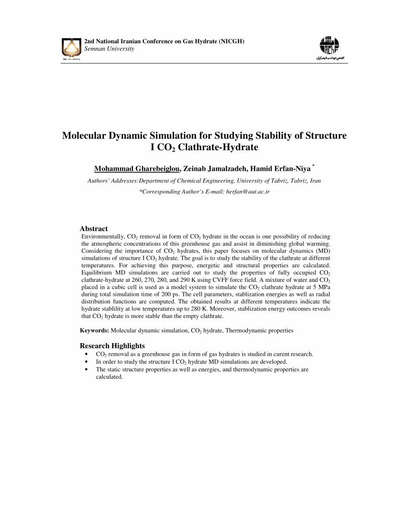
Four decades ago, van der Waals and Plateeuw (vdWP) [9] reported a thermodynamic model (vdWP model) to calculate the dissociation pressure of hydrates, and most subsequent models [5] used the vdWP model as a basis [4]. The objective of our current research is to investigate the stability of structure I CO2 hydrate by studying structure and thermodynamic quantities computed at P = 5 MPa and different temperatures. The properties are studied using molecular dynamic simulations with Materials Studio software suit. 2.Models and Methods The applied model system of structure I CO2 clathrate-hydrate was a periodic 2*2*2 supper cell of SI CO2 hydrate represented in Fig. 1. To form the CO2 hydrate, the clathrate was filled with one CO2 molecule in each cage. Each cell has 8 cages, and the system involves of 8 unit cells. So, the model system of CO2 hydrate contains 64 CO2 and 368 H2O molecules. The hydrate structure consists of 2 cavities formed by hydrogen-bonded water molecules shown in Fig. 2.The small cavity is a pentagonal dodecahedron framework (12-sided cavity) labeled as (512) because it has 12 pentagonal faces with equal edge lengths and equal angles; and the large cavity is a 14-sided cavity (tetrakaidecahedron) called (51262) because it has 12 pentagonal and 2 hexagonal faces. The initial positions of H2O molecules in model systems are taken from X-ray diffraction measurements [10] where the gas (CO2) molecules are encaged in the center of cavities.
Fig. 1. Schematic of structure I CO2 Hydrate
NPT- (constant number of atoms, pressure and temperature) molecular dynamics (MD) simulations were performed using the cvff force field in the Materials Studio package. The simulation pressure was 5MPa and data collection temperatures were varied from 260 to 290 K, which were close to the undersea temperatures. The temperatures and pressure of the model system were controlled using Andersen [11] and Berendsen [12] methods, respectively. The integration time step of 1 fs and total simulation time of 200 ps were typically employed

MD Simulation for Studying Stability……
at each temperature. In order to make sufficient movements of the gas molecules, the position and orientation of H2O molecules are fixed in the first 5 ps simulations during the energy optimization.
Fig. 2. Cavities in CO2 clathrate hydrates: (a) small cavity (512), (b) large cavity (512 62)
2.1. Computational details
The overall procedure for evaluating thermodynamic property of CO2 hydrate is summarized in three steps comprising structure optimization, equilibration, and calculation of properties. Before proceeding through all these steps the force field has to be defined in order to establish the interaction protocol among atoms.
2.1.1. Force Field As mentioned earlier, CVFF force field was used to define the bonded and non-bonded interactions among atoms using the following Equation 1:
� � ����� � ���� � �� ��� � ������ � ���� ��� � ������� � ���� (1)
where the subsequent terms are used: E: Total potential energy, Ebond: Bond energy, Eangle: Angle energy, Eimproper: Improper or out-of-plane energy, Ecoulomb: Coulombic energy, EVDW: Energy due to Van der Waals interaction.
The cutoff distance of 15.0 Å was used in defininig the long range interaction by Lennard-Jones potential. The van der Waals and long-range Coulomb interactions were calculated using the Ewald summation method. The Verlet velocity algorithm [13] is used to obtain accurate integrations and statistical ensembles and random velocities from Boltzmann distribution was used as the initial velocities.
2.1.2.CO2 hydrate and structure optimization The initial structure I CO2 hydrate consists of 8 CO2 molecules and 46 water molecules in each unit. Initially, the atoms in the cell were subjected to molecular dynamic simulation with the cvff force field. The optimized structure of CO2 hydrate is represented in Fig. 3. This structure was used as repeat unit for hydrate molecule in later sections.

2nd National Iranian Conference on Gas Hydrate (NICGH) Semnan University
Fig. 3. Optimized structure of CO2 hydrate
2.1.3. Equilibrium properties of clathrate crystal The optimized CO2 hydrate structure was repeated in dimensions of 2*2*2. The obtained super cell was gone through for NPT MD simulations. The static structure properties such as cell parameters and densities as well as energies, and thermodynamic properties were calculated. The CO2 molecules in the large and small cavity were simulated as two distinct components. Hence the properties of the CO2 in the large and small cavities can be analysed separately.
2.1.4. Thermodynamic calculation In order to study the stability of the hydrate, thermodynamic properties are calculated. In principle, if the molecular geometry, energy, and vibrational frequencies are known, the thermodynamics properties comprising enthalpy (H), entropy (S), free energy (G), and heat capacity at constant pressure (Cp) of the molecule can be calculated. The various translational, rotational, and vibrational components are used to compute H, S, G, and Cp at finite temperatures as discussed below [14]. In each case, two expressions are provided for rotational contributions: one for linear and one for nonlinear systems. 2.1.4.1 Enthalpy The enthalpy corretion, H, is given by:
� � � � �� (2) � � ���� � � !" � �" #$% (3)
Where the subscripts stand for vibrational, rotational, and translational contributions, respectively, and R is the ideal gas constant. The thermal energy correction contributions are given by:
�" # � &'�� (4)
� !"()*+,-./ � �� (5)
� !"(+0+)*+,-./ � &'�� (6)
���� � +�∑ 2345� 67' � 7
9:;(234 5</=7⁄ ? (7)
where νi are the vibrational frequencies, k is Boltzmann’s constant, and h is Planck’s constant.
2.1.4.2. Entropy The contributions to the entropy, s, are given by:
@ � +� ∑ 6 234/5<9:;(234 5</=7⁄ � ln(1 � exp(HI� J�/⁄ /?� (8)
where σ is the symmetry number (σ = 2 for both H2O and CO2 ), and the other quantities are as described above.
2.1.4.3. Free energy
The Gibbs free energy, G, is be obtained from the enthalpy, temperature, and entropy [14]:
K � � � �@(9)

MD Simulation for Studying Stability……
3.Result and Discussion The results obtained from MD simulations and thermodynamic energies calculations are summerized in the following sections. 3.1.Parameterization The variation of the cell sizes constant of CO2 hydrate with simulation time examined by carrying out NPT MD simulations. The results signified that the cell size of CO2 hydrate increase continually at higher temperatures, while that of low temperatures will keep steady, as shown in Fig. 4. That means the decomposition of CO2 hydrate is much severer at high temperatures specifically more in 290 K than that at 260 and 270 K.
Fig. 4. Cell size of CO2 hydrate at P = 5 MPa and (a) T = 260K, (b) T = 270K, (c) T = 280K, (d) T= 290K
3.2.Final arrangements of CO2 hydrate
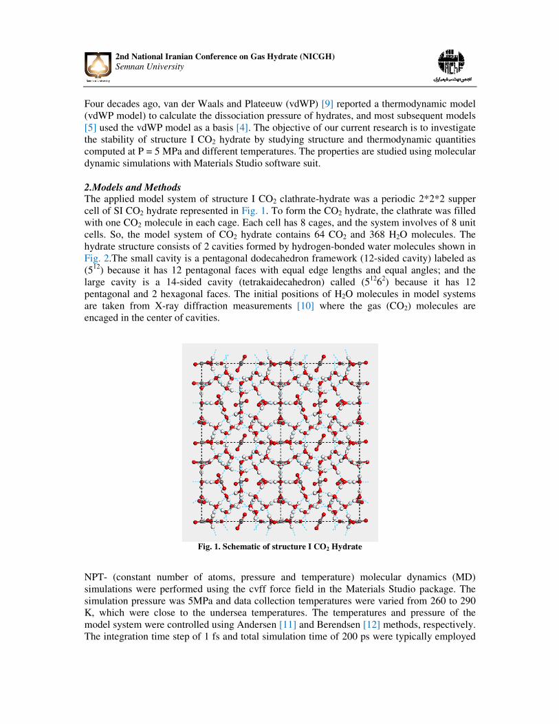
Fig. 5(a-d) demonstrates the snapshots of the final arrangements of CO2 hydrate at pressure of 5 MPa and temperatures T = 260, 270, 280, and 290 K, respectively. The images reveal that the crystal structure of CO2 hydrate can keep stable at 260 K. Moreover, it can be observed the hydrogen bonding network in CO2 hydrate start to collapse after temperature of 270 K as indicated in Fig. 5(b-d); however, no aggregation of CO2 molecules observed. When the system temperature grows to 290K, obvious aggregation of CO2 molecules appears in decomposed CO2 hydrate.
11.8
11.9
12
12.1
12.2
12.3
12.4
12.5
0 20 40 60 80 100 120 140 160 180 200
Cel
l siz
e (Å
)
t (ps)
(a)
(b)
(c)
(d)
2nd National Iranian Conference on Gas Hydrate (NICGH) Semnan University
Fig. 5. Snapshots of MD simulations of CO2 hydrate at 5 MPa and (a) T=260K, (b) T=270K, (c) T=280K, (d) T= 290K 3.3. Radial Distribution Function (RDF)
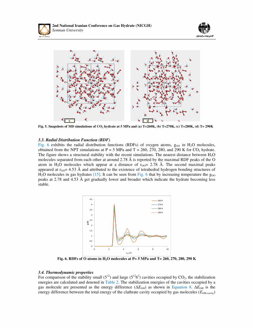
Fig. 6 exhibits the radial distribution functions (RDFs) of oxygen atoms, gOO in H2O molecules, obtained from the NPT simulations at P = 5 MPa and T = 260, 270, 280, and 290 K for CO2 hydrate. The figure shows a structural stability with the recent simulations. The nearest distance between H2O molecules separated from each other at around 2.78 Å is reported by the maximal RDF peaks of the O atom in H2O molecules which appear at a distance of rOO= 2.78 Å. The second maximal peaks appeared at rOO= 4.53 Å and attributed to the existence of tetrahedral hydrogen bonding structures of H2O molecules in gas hydrates [15]. It can be seen from Fig. 6 that by increasing temperature the gOO peaks at 2.78 and 4.53 Å get gradually lower and broader which indicate the hydrate becoming less stable.
Fig. 6. RDFs of O atoms in H2O molecules at P= 5 MPa and T= 260, 270, 280, 290 K
3.4. Thermodynamic properties For comparison of the stability small (512) and large (51262) cavities occupied by CO2, the stabilization energies are calculated and denoted in Table 2. The stabilization energies of the cavities occupied by a gas molecule are presented as the energy difference (∆EGH) as shown in Equation 8. ∆EGH is the energy difference between the total energy of the clathrate cavity occupied by gas molecules (EGH-cavity)
0
0.5
1
1.5
2
2.5
3
3.5
4
4.5
0 2 4 6 8 10
g (
r)
roo (Å )
260 K
270 K
280 K
290 K
MD Simulation for Studying Stability……
and the sum of the corresponding number of H2O (Ewater) and CO2 molecules (Egas) involved in the cavity occupied by the gas molecule.
Δ�MN � �MN=OPQRST � (+�U'V �W�XV'/ (10)
where n is the number of H2O molecules of the cavity which is 20 for the small cavity and 24 for the large cavtity, and m is the number of CO2 molecules of the cavity which is zero for the empty cavity and one for the full cavtity. Moreovere, the energy contents of CO2 and H2O is -118662.7538 and -48076.72585 kcal/mol, respectivelly.
Table 2. Stabilization Energies of Different Cavities (kcal/mol)
Full cavity Empty cavity Small cavity (512) -239.3172654 -232.4763872 Large cavity (51262) -293.9689997 -279.7090665
The calculated stabilization energy of full cavity is somewhat smaller than that of empty cavity that signified the presence of CO2 made the hydrate to be more stable. Besides, the comparison of the stabilization energy of CO2 (5
12) and CO2 (51262), where attributed to the CO2 molecules encaged in the
small and large cavities, correspondingly, suggests that CO2 (512) is less stable than CO2 (5
1262). This reveals that the decomposition of the small cavity in the CO2 hydrate proceeded more quickly than that of the large because the CO2 molecule is too large to be encaged in the small cavity. Furthermore, the enthalpies, entropies, and free energies for the large cavity are given in Table 3. In a similar manner to the stabilization energies description, from Table 2 it can be seen that the enthalpy for the fully occupied cavity is smaller than the empty one, where thus empty structure is less stable and adding the guest molecule leads the structure to be more stable. These relative orderings are valid also for the entropies. However, when Gibbs free energies are considered, empty cavity becomes more stable. The properties calculated for the small cavity were in the same manner.
Table 3. Thermodynamic properties of Different Cavities
Full cavity Empty cavity ∆H ∆S ∆G
-20.93 -0.8217 224.13
-18.384 -0.7823 223.358
8.Conclusions
In this paper, the structure of type I CO2 hydrate has successfully been modeled by molecular a dynamic (MD) simulation with the aim of CO2 storage which is favorable for mitigating greenhouse gases form environment. Thermodynamic and structure properties of the fully occupied type SI CO2 hydrate have been predicted for studying the stability of the hydrate at P=5 MPa and T = 260, 270, 280, and 290 K. Combining the results from MD simulations with the thermodynamic properties calculations, one concludes that the CO2 hydrate exhibits the best stability at temperatures under 280 K. The RDFs of goo revealed the crystal structure of the hydrate decomposes by temperature increasing and collapse at 290 K. A comparison of the thermodynamic properties indicates that the empty hydrate is less stable than fully occupied CO2 hydrate. Furthermore, a comparison of the stabilization energies of the small and large

2nd National Iranian Conference on Gas Hydrate (NICGH) Semnan University
cavities containing CO2 demonstrates that the CO2 molecule is less suitable for the small cavity but is more suitable for the large cavity. Acknowledgements
The authors gratefully acknowledge University of Tabriz for the financial support of the project as well as Iran Nanotechnology Initiative Council for complementary financial support. Nomenclature
Y � Å Z[ \\ νi J H S H G σ
Pressure, N/m2 Temrperature, K Angstrom Molecular Dynamic simulation Force Field Vibrational frequencies Boltzmann’s constant Planck’s constant Entropy Enthalpy Gibbs free energy Rotational symmetry number References [1] H. Müller,"Feste gashydrate II. Struktur und Raumchemie". Zeitschrift für Elektrochemie,
Berichte der Bunsengesellschaft für physikalische Chemie, Vol. 58, pp. 25-39, 1954. [2] J.A. Ripmeester, S.T. John, C.I. Ratcliffe, and B.M. Powell,"A new clathrate hydrate structure".
Nature, Vol. 325, pp. 135-136, 1987. [3] C. Koh, R. Westacott, W. Zhang, K. Hirachand, J. Creek, and A. Soper,"Mechanisms of gas
hydrate formation and inhibition". Fluid Phase Equilibria, Vol. 194, pp. 143-151, 2002. [4] S. Zele, S.Y. Lee, and G. Holder,"A theory of lattice distortion in gas hydrates". The Journal of
Physical Chemistry B, Vol. 103, pp. 10250-10257, 1999. [5] E.D. Sloan Jr, and C. Koh, Clathrate hydrates of natural gases, CRC, 2007. [6] K.A. Udachin, C.I. Ratcliffe, and J.A. Ripmeester,"Structure, composition, and thermal expansion
of CO2 hydrate from single crystal X-ray diffraction measurements". The Journal of Physical Chemistry B, Vol. 105, pp. 4200-4204, 2001.
[7] B. Pierce, and T. Collet, Energy Resource Potential of Natural Gas Hydrates, Proceedings of the 5th Conference & Expositon on Petroleum Geophysics, 2005.
[8] A. Hunt,"Fluid properties determine flow line blockage potential". Oil and Gas Journal, Vol. 94, pp., 1996.
[9] J. Waals, and J. Platteeuw,"Clathrate solutions". Advances in Chemical Physics, Vol. 2, pp. 1-57, 2007.
[10] K.A. Sparks, Configurational properties of water clathrates through molecular simulation, Ph.D. Thesis, Massachusetts Institute of Technology, 1991.
[11] H.C. Andersen,"Molecular dynamics simulations at constant pressure and/or temperature". The Journal of Chemical Physics, Vol. 72, pp. 2384, 1980.

MD Simulation for Studying Stability……
[12] H.J.C. Berendsen, J.P.M. Postma, W.F. van Gunsteren, A. DiNola, and J. Haak,"Molecular dynamics with coupling to an external bath". The Journal of Chemical Physics, Vol. 81, pp. 3684, 1984.
[13] L. Verlet,"Computer" experiments" on classical fluids. I. Thermodynamical properties of Lennard-Jones molecules". Physical Review, Vol. 159, pp. 98, 1967.
[14] J.J.P. Stewart,"MOPAC Manual". Constraints, Vol. 3, pp. 2, 1993. [15] L. Ding, C. Geng, Y. Zhao, and H. Wen,"Molecular dynamics simulation on the dissociation
process of methane hydrates". Molecular Simulation, Vol. 33, pp. 1005-1016, 2007.