jamaica generation code 2013
DESCRIPTION
Jamaica Generation Code 2013TRANSCRIPT

JAMAICA
Electric Utility
Sector
Generation
Code
[July 2013]

DOCUMENT TITLE AND APPROVAL PAGE
DOCUMENT NUMBER: 2013/003/ELE/TEC/001
1. DOCUMENT TITLE: Electric Utility Sector Generation Code, July 2013
2. PURPOSE OF DOCUMENT This document covers the guiding principles, operating procedures and Technical Standards governing operation of the Jamaican Electric Power Grid and all interconnected Generating Facilities. The Code seeks to facilitate the economic, safe and reliable operation of the Jamaican Power Grid and to avoid any undue discrimination among Generators. The provisions of the Code are enforceable under the Office of Utilities Regulation (OUR) Act 1995 (as amended) as well as the Amended and Restated All-Island Electric Licence 2011 and any other applicable enactment.
3. RECORD OF DOCUMENT ON ISSUE
Document Number Description Date
Electric Utility Sector Generation Code November 1997
4. APPROVAL
This document is approved by the Office of Utilities Regulation and the provisions therein become effective August 1, 2013. On behalf of the Office:
…………………………….. Maurice Charvis Director General July 29, 2013

Electric Utility Sector Generation Code Document No. 2013/003/ELE/TEC/001 July 2013
iii
TABLE OF CONTENTS LIST OF REVISIONS ........................................................................................................ ii
PREFACE ......................................................................................................................... vii
INTERPRETATION OF CODE........................................................................................ ix
1 CONNECTION CONDITIONS ................................................................................... 1
1.1 METHOD OF CONNECTION ........................................................................................ 1
1.1.1 INTERCONNECTION POINT ................................................................................ 2
1.1.2 SUPPLY VOLTAGE ................................................................................................ 2
1.1.3 CONFIGURATION OF GENERATION SUBSTATIONS ..................................... 2
1.2 GENERATOR PERFORMANCE STANDARDS AND TECHNICAL ......................... 3
CRITERIA .................................................................................................................................. 3
1.2.1 TECHNICAL STANDARDS ................................................................................... 3
1.2.2 PERFORMANCE STANDARDS ............................................................................ 3
1.2.3 STATION CAPABILITIES...................................................................................... 4
1.2.4 PROTECTION REQUIREMENTS .......................................................................... 6
1.3 GRID OPERATOR PERFORMANCE AND TECHNICAL STANDARDS ................. 7
1.4 OTHER RIGHTS VESTED WITH THE GRID OPERATOR ........................................ 8
1.4.1 INSPECTION OF GENERATING PLANT BY GRID OPERATOR ..................... 8
1.4.2 DISCONNECTION OF GENERATOR BY THE GRID OPERATOR................... 9
2 OPERATIONAL METERING ................................................................................... 10
2.1 TECHNICAL STANDARDS FOR OPERATIONAL METERING ............................. 10
2.1.1 LOCATION OF METERING EQUIPMENT ........................................................ 10
2.1.2 METERING STANDARDS ................................................................................... 10
2.1.3 SEALING, FIELD TESTING AND INSPECTION OF METERING SYSTEMS 11
2.2 METER READING PROCEDURES ............................................................................ 12
2.2.1 PARAMETERS FOR METER READING ............................................................ 12
2.2.2 FREQUENCY OF READING ............................................................................... 12
2.2.3 CONTROL PROCEDURES ................................................................................... 13
2.2.4 METERING REQUIREMENTS FOR GENERATORS <100KW ........................ 13
2.3 RECONCILIATION PROCEDURES ........................................................................... 13
Electric Utility Sector Generation Code Document No. 2013/003/ELE/TEC/001 July 2013
iv
2.4 RESOLUTION OF DISPUTES OVER RECORDED METERING DATA ................. 14
3 GENERATOR SCHEDULING AND DISPATCH ................................................... 15
3.1 CRITERIA FOR SCHEDULING AND DISPATCH .................................................... 15
3.2 MERIT ORDER SCHEDULING .................................................................................. 15
3.2.1 REVIEW OF MERIT ORDER AND DISPATCH INPUT .................................... 16
3.3 NOTIFICATION OF MERIT ORDER.......................................................................... 18
3.4 SYSTEM SECURITY STANDARDS .......................................................................... 18
3.4.1 SPINNING RESERVE ........................................................................................... 18
3.4.2 OPERATING RESERVE ....................................................................................... 18
3.5 UNIT COMMITMENT SCHEDULING AND SYSTEM OPERATION ..................... 19
3.5.1 PREPARATION OF UNIT COMMITMENT SCHEDULE .................................. 19
3.6 DISPATCH INSTRUCTIONS ...................................................................................... 21
3.6.1 INSTRUCTION TO SYNCHRONIZE / DESYNCHRONIZE .............................. 22
3.6.2 FREQUENCY AND VOLTAGE CONTROL ....................................................... 22
3.6.3 CHANGES TO GENERATION CONDITIONS ................................................... 23
3.7 SWITCHING INSTRUCTIONS.................................................................................... 24
3.8 NON CENTRALLY DISPATCHED PLANT ............................................................... 25
3.9 COMMUNICATION AND REPORTING .................................................................... 25
3.9.1 DESIGNATED CONTACT PERSONS ................................................................. 25
3.9.2 SYSTEM CONTROL CENTER RECORD OF DISPATCH ................................ 25
3.9.3 GENERATOR OPERATIONS LOG ..................................................................... 27
3.10 FUEL SUPPLY AGREEMENT ................................................................................. 28
3.11 GENERATOR SCHEDULING & DISPATCHING TOOLS .................................... 29
3.12 TRANSPARENCY AND FAIRNESS ....................................................................... 29
3.13 NEW TECHNOLOGIES ............................................................................................ 30
4 LOAD SHEDDING AND POWER RESTORATION .............................................. 31
4.1 LOAD SHEDDING PROCEDURES ............................................................................ 31
4.1.1 UNDER FREQUENCY (AUTOMATIC) LOAD SHEDDING............................. 31
4.1.2 MANUAL LOAD SHEDDING ............................................................................. 32
4.2 CONTINGENCY PLANS FOR POWER RESTORATION ......................................... 33

Electric Utility Sector Generation Code Document No. 2013/003/ELE/TEC/001 July 2013
v
4.2.1 PROCEDURES FOR RESTORATION OF POWER FOLLOWING ................... 33
WIDESPREAD BLACKOUT .............................................................................................. 33
5 GENERATOR MAINTENANCE PLANNING ........................................................ 35
5.1 LONG TERM MAINTENANCE .................................................................................. 35
5.1.1 PLANNING HORIZON ......................................................................................... 35
5.1.2 ANNUAL COMMITMENT OF MAINTENANCE PROGRAM .......................... 35
5.1.3 CHANGES TO THE COMMITTED MAINTENANCE SCHEDULES ............... 36
5.2 SHORT TERM OUTAGE PROGRAM ........................................................................ 37
6 TESTING AND MONITORING ............................................................................... 38
6.1 PROCEDURES FOR CONDUCTING TESTS ............................................................. 38
6.2 STANDARD TESTS ..................................................................................................... 38
6.2.1 TEST PRIOR TO FIRST SYNCHRONIZATION ................................................. 38
6.2.2 TESTS AFTER FIRST SYNCHRONIZATION .................................................... 39
6.3 CO-GENERATORS AND NON-DISPATCHABLE GENERATORS ........................ 42
6.4 TESTING OF METERING SYSTEM ........................................................................... 42
6.5 PARAMETERS MONITORING ................................................................................... 42
7 GENERAL PROVISIONS ......................................................................................... 43
7.1 MATTERS TO BE AGREED........................................................................................ 43
7.1.1 OUR RULINGS AND DIRECTIONS ................................................................... 43
7.1.2 OTHER AGREEMENTS ....................................................................................... 43
7.1.3 TREATMENT OF THIRD PARTY CONTRACTS .............................................. 43
7.2 MONITORING AND REVIEW OF THE GENERATION CODE .............................. 44
7.2.1 THE ROLE OF THE OUR ..................................................................................... 44
7.2.2 THE GENERATION CODE REVIEW PANEL .................................................... 44
7.2.3 REVISIONS OF THE CODE ................................................................................. 46
7.3 UNFORESEEN CIRCUMSTANCES AND SYSTEM EMERGENCIES .................... 47
7.3.1 UNFORESEEN CIRCUMSTANCES .................................................................... 47
7.3.2 FORCE MAJEURE ................................................................................................ 47
7.4 NON-COMPLIANCE .................................................................................................... 47
7.5 DEROGATION .............................................................................................................. 48

Electric Utility Sector Generation Code Document No. 2013/003/ELE/TEC/001 July 2013
vi
7.5.1 NORMAL PROCEDURE WHEN NON-COMPLIANCE IS ................................ 48
7.5.2 DEROGATION FOR EXISTING APPARATUS NOT IN COMPLIANCE ........ 49
7.6 DISPUTE RESOLUTION ............................................................................................. 49
7.6.1 MUTUAL DISCUSSION ....................................................................................... 49
7.6.2 REFERRAL AND DETERMINATION BY THE OUR........................................ 49
7.7 NOTICES ....................................................................................................................... 51
SCHEDULE A: TERMS AND DEFINITIONS ............................................................... 53
SCHEDULE B: REQUIRED COMMUNICATION EQUIPMENT ................................ 60
SCHEDULE C: LOAD SHEDDING SCHEME .............................................................. 62
SCHEDULE D: RESERVE MARGIN POLICY ............................................................. 63
SCHEDULE E: EXISTING GENERATING SYSTEM .................................................. 64
SCHEDULE F: GRID OPERATOR INTERCONNECTION CRITERIA ...................... 66

Electric Utility Sector Generation Code Document No. 2013/003/ELE/TEC/001 July 2013
vii
PREFACE
The Generation Code (hereinafter called the "Code") covers the guiding principles, operating
procedures and Technical Standards governing operation of the Jamaican Electric Power System
Grid and all interconnected Generating Facilities. The Code seeks to facilitate the economic, safe
and reliable operation of the Jamaican Power System and to avoid any undue discrimination
among Generators. The provisions of the Code are enforceable under the Office of Utilities
Regulation Act 1995 (as amended), the Amended and Restated All Island Electric Licence 2011
and any other applicable enactment.
The Code is divided into the following sections:
Connection Conditions specifies the normal method of connection and the minimum technical,
design and operational criteria which must be complied with by all Generators and prospective
Generators.
Operational Metering specifies the Technical Standards and procedures for metering applicable
to Metering Systems installed by Generators.
Generation Scheduling and Dispatch specifies the procedures for Generating Unit scheduling,
dispatch, System security and communications between Generators and The Grid Operator via
the System Control Center.
Load Shedding and Power Restoration specifies the procedures for automatic and manual
shedding of load and restoration of power following partial or total black out.
Generator Maintenance Planning specifies the criteria and procedures governing the planning
and scheduling of maintenance requirements of Generators' Generating Facilities.
Testing and Monitoring specifies the list, time table and procedures for all tests to be performed
by the Generator and Grid Operator.
General Provisions encompass several provisions pertinent to the functioning of the Code,
including procedures for review of the Code and for derogation of existing installations and
equipment not in compliance with the standards specified in this Code at the time of execution.
Jamaica Public Service Company Limited ("JPS") has responsibilities under this Code in two
distinct capacities. These are as follows:
i) JPS is responsible for prudent and efficient management of the Jamaican Electric Power
System and, in that capacity, for dealing with all Generators in a consistent and non-
discriminatory manner. This Code applies the term "Grid Operator" whenever referring to
JPS in this capacity;

Electric Utility Sector Generation Code Document No. 2013/003/ELE/TEC/001 July 2013
viii
ii) As the owner of power stations, JPS is also subject to the rights and obligations in this
Code as apply to Independent Power Producers (“IPPs”) and Co-generation Facilities.
Any reference to "Generators" in this Code should be interpreted to include JPS in this
capacity.

Electric Utility Sector Generation Code Document No. 2013/003/ELE/TEC/001 July 2013
ix
INTERPRETATION OF CODE In this code:
i) Expressions defined under ‘Terms and Definitions' (Schedule A) shall bear the
respective meaning set out therein;
ii) The headings are for convenience only and shall not be used in construing the Code;
iii) The singular includes the plural and vice versa;
iv) Terms not herein defined shall have the meaning ascribed thereto in the Oxford
English Dictionary, such meaning as ascribed under the relevant statute and
regulations as well as such meaning as normally ascribed and accepted within the
power industry ; and
v) References to clauses, recitals and schedules are, unless the contents otherwise
requires, references to clauses of and recitals and schedules to this Code.

Electric Utility Sector Generation Code Document No. 2013/003/ELE/TEC/001 July 2013
1
1 CONNECTION CONDITIONS Connection Conditions specifies the normal method of connection and the minimum
technical, design and operational criteria which must be complied with by any Generator
and prospective Generators.
Additionally, details specific to each Generator's connection may be set out in a separate
Connection Agreement or in some cases, the relevant Power Purchase Agreement. The
Connection Conditions set out in the Code shall be read in conjunction with either or both
of these Agreements as relevant. In the event that, there is any conflict between the
provisions of the Code and any Connection Agreement and/or Power Purchase
Agreement and the said Connection Agreement and/or Power Purchase Agreement was
signed before the present Code came into effect, then, the provisions of the Connection
Agreement and/or Power Purchase Agreement will supersede the Code. Notwithstanding
the foregoing, all Connection Agreements and/or Power Purchase Agreements shall be
read in conjunction with the Code in force at any material time and in accordance with
Sub-section 7.1 of this Code.
1.1 METHOD OF CONNECTION The method of connection shall be determined on the basis of several technical and economic factors which include: i) Proximity to System Grid;
ii) Generating Unit (MW) rating or Generating Facility (MW) capacity;
iii) Supply voltage;
iv) Reliability considerations;
v) Auxiliary power supply;
vi) Substation configuration;
vii) Protection systems/devices; and
viii) Costs
It will not be technically or economically practicable to achieve uniformity of the method
of connection. In all cases however, Prudent Utility Practice will influence the method
adopted.
The method chosen by the Generator shall be reviewed and approved by the Grid
Operator on the grounds of System security, stability and safety.

Electric Utility Sector Generation Code Document No. 2013/003/ELE/TEC/001 July 2013
2
1.1.1 INTERCONNECTION POINT The Generating Unit(s) shall be interconnected to the System Grid via a Substation. The
Interconnection Point shall normally be on the High Voltage side (System Grid side) of
the generator step-up transformer and will demarcate the boundary of responsibility
between the Generator and the Grid Operator.
Generators, with capacity of 60 MW or more shall be interconnected to the
switchyard/substation to satisfy the N-1 security criteria. This implies that the loss of any
single Transmission element connecting a Generator to the Transmission System shall
not result in a loss of generating capacity greater than 60 MW.
The finalized number of connection points shall be determined by a system analysis study
at the time of interconnection to the system.
The Generator shall be responsible for all costs related to interconnection to the Grid.
1.1.2 SUPPLY VOLTAGE The voltage level at which the Generating Unit(s) are connected to the System Grid will be dependent on but not limited to the size and number of units and the other factors that determine the Interconnection Point. Subject to other technical considerations, Generating Units with a Rated Capacity of 10 MW or above shall be connected to the Transmission System at 69 kV or 138 kV. Generating Units with a Rated Capacity of below 10 MW may be connected to either the
Transmission System at 69 kV or 138 kV or the primary Distribution System at 24 kV or
less.
Embedded Generating Facilities with Rated Capacity between 1MW and 10MW may be
interconnected via a dedicated feeder recloser from the Substation to the Facility.
1.1.3 CONFIGURATION OF GENERATION SUBSTATIONS
All Generation Substations shall have the capability to disconnect or separate, from the
System Grid, any transmission line and Generating Unit which is interconnected to the
Substation.
For reasons of ensuring safety and reliability of operation, Generation Substations with
more than three transmission lines and Generating Units interconnected to them shall be
of a ‘breaker and a half’ configuration. The size of the Generating Units shall be
considered for applicability of the breaker and a half requirement. The Substation shall be

Electric Utility Sector Generation Code Document No. 2013/003/ELE/TEC/001 July 2013
3
equipped with all requisite protection measures necessary to meet the Grid Operator's
System protection standards as set out in Clause 1.2.4.
1.2 GENERATOR PERFORMANCE STANDARDS AND TECHNICAL
CRITERIA
1.2.1 TECHNICAL STANDARDS All components of the connection shall be constructed, installed and tested in accordance with the current edition at the time of construction of the following codes and standards, or their international equivalents and Prudent Utility Practice:
ACI American Concrete Institute
ANSI American National Standards Institute
ASCE American Society for Civil Engineers
ASME American Society for Mechanical Engineers
ASNT American Society for Non-Destructive Testing
ASTM American Society for Testing Materials
AWS American Welding Society
UL Underwriters Laboratory
IEC International Electrotechnical Commission
IEEE Institute of Electrical and Electronic Engineers
ISO International Organization for Standardization
NBC National Building Code (Jamaica)
NIST National Institute of Standards and Technology
NEC National Electric Code
NEMA National Electric Manufacturers Association
NESC National Electric Safety Code
NETA National Electric Testing Association
NFPA National Fire Protection Association
SSPC Steel Structures Painting Council
BSJ Bureau of Standards Jamaica
NEPA National Environmental Planning Agency (Jamaica)
OSHA Occupational Safety and Health Administration
1.2.2 PERFORMANCE STANDARDS Each Generating Unit interconnected to the System Grid shall be required, as a minimum, to meet the following performance standards:

Electric Utility Sector Generation Code Document No. 2013/003/ELE/TEC/001 July 2013
4
i) Sustained operation at any Load within the loading limits within the System
frequency range of 49.5 Hz to 50.5 Hz;
ii) Emergency operation within the Generator loading limits and within the system frequency range of 48.0 Hz to 52.5 Hz;
iii) Maintain normal rated output at the System Grid normal voltages specified in
Sub-section 1.3; iv) Sustained operation at the rated Power Factor set out in the relevant and
appropriate Interconnection Agreement; and v) Grid Interconnection Criteria (Appendix G)
1.2.3 STATION CAPABILITIES i) Synchronizing Facilities
Each Generating Unit shall be equipped with synchronizing facilities to ensure
Synchronization with the System Grid. Two independent synchronizing facilities,
preferably one automatic and one manual shall be provided, however, the primary must
be automatic. The Synchronization facilities shall include a synchronism check relay to
support synchronization under the following range of conditions:
a) System Grid frequency within the limits 48.0 to 52.5 Hz; and
b) System Grid voltages within the limits specified in Sub-section 1.3. ii) Auxiliary Supply
Each Generating Unit shall have the facility to provide its auxiliary supply during normal
operation. Each Generator shall provide the facility to connect to the System Grid for an
incoming station service supply from the Grid Operator.
iii) Automatic Frequency Response
It is required that Dispatchable Generating Units have continuously fast acting response
automatic governor and excitation control systems to control the Generating Unit's power
output and voltage levels without instability of operation within the operating range of
the unit.

Electric Utility Sector Generation Code Document No. 2013/003/ELE/TEC/001 July 2013
5
iv) Governor Response Capability
The droop characteristics from no load to full load for Generating Units shall be
adjustable in the range of (0 - 5%).
v) Black Start Capability and Dead Bus Control
Some Generating Units shall be designated to have Black Start Capability primarily
considering their type and location on the system. This shall enable Generators to restart
their facilities without incoming supply from the System Grid, connect to a Dead Bus,
and supply load as necessary; once on line Generators are required to be in frequency
sensitive mode so as to vary with load changes. In the event of the Generator “black
starting” the Grid, the Generator may act, temporarily upon the provision of instructions
from the Grid Operator.
The specification of the Black Start Generating Unit shall be a subject of the
Interconnection Agreement (normally contained in the PPA as a Schedule) between the
Grid Operator and the Generator.
Where a Generator has a facility with a capacity of 60MW (excluding intermittent
renewables with high and rapid variability) or greater, at least one source of Black Start
supply shall be located at the site. Black Start facilities shall be routinely tested by the
Generator to ensure satisfactory operation. The Grid Operator shall have the right to
require the Generator to demonstrate the performance of the Black Start Capability. At a
minimum, the Generator is required to provide a formal report to the Grid Operator twice
a year, detailing the results of the Black Start generator test. One of these reports must be
based on a test done in May of that year and shall be submitted to the Grid Operator
before June 1 (the official start of the hurricane season). A failed event shall
automatically trigger the reporting of that black start test event by the relevant Generator
to the Grid Operator. A further report is also to be immediately submitted by the
Generator to the Grid Operator upon subsequent successful maintenance and operation of
said black start generator.
vi) Fuel Supply Capability (Thermal Plants only)
The Generator shall at its own expense construct and maintain fuel supply infrastructure
sufficient to store at least eighteen (18) days of fuel requirement at normal rated output
subject to the provisions of Sub-section 3.10.

Electric Utility Sector Generation Code Document No. 2013/003/ELE/TEC/001 July 2013
6
1.2.4 PROTECTION REQUIREMENTS i) Protective systems shall be provided in accordance with the Technical Standards set
out in Clause 1.2.1 and Prudent Utility Practice as generally accepted in the power industry.
ii) All protective relaying equipment shall comply with the appropriate Technical
Standards.
iii) At a minimum, the following protection schemes shall be provided subject to the
exigencies of the relevant generation technology including inter alia;
AC generators (Reference is made to IEEE Guidelines 37.102.2006)
a) Loss of Excitation (Under-reactance type)
b) Differential current protection (for generator phase-to-phase fault)
c) Negative phase sequence protection (for unbalanced load operation)
d) Stator ground fault protection (for generator phase-to-ground faults)
e) Reverse power protection
f) Backup protection in the event of circuit breaker failure to operate.
g) Over- and under-frequency
h) Over- and under-voltage
i) Thermal over-load
j) Rotor (or field) ground fault protection
Transformers (Reference is made to IEEE Guidelines 37.91.2000)
a) Differential current protection for generator step-up transformers
b) HV/LV phase and ground overcurrent protection (for station service/unit auxiliary
transformers)
c) Buchholz and/or Sudden pressure (gas relay)
d) Over excitation protection (for generator step-up transformers)
e) Backup protection in the event of circuit breaker failure to operate for generator
step-up transformers
f) Over-temperature protection (winding and oil)
Interconnection
a) Differential (line current high-impedance) for Phase and earth faults.
b) Backup interconnection protection in the event that external phase and earth faults
are not cleared by remote protection system.
c) Backup protection in the event of circuit breaker failure to operate.

Electric Utility Sector Generation Code Document No. 2013/003/ELE/TEC/001 July 2013
7
iv) The protection requirements for the HV interconnection with System Grid will
depend on the connection voltage and the Substation configuration. The detailed
arrangements for each Generating Facility are set out in the respective
Interconnection Agreement. In all cases it should be ensured that each Generating
Unit or Facility can be separated from the System Grid as rapidly as possible in the
event of a sustained electrical fault on either side of the Interconnection Point. The
speed of separation shall be determined by the Interconnection Criteria.
v) The protective relaying systems shall provide the levels of sensitivity, speed and
reliability as required by the Grid Operator. The operation of all protection schemes
shall be coordinated with the operation of the Grid Operator's equipment.
vi) The Generator shall submit the following design data for prior approval by the Grid
Operator:
a) Protection and Metering single line diagrams;
b) Tripping logic diagrams;
c) AC and DC schematic diagrams for the interconnection and Generating Unit
protection schemes;
d) Setting calculations and setting lists for the interconnection and Generating Unit
protection schemes including opening/closing time for major circuit breakers; and
e) Rating and Transfer Function data as required for computer simulation of the
Generating Unit(s). This shall include data on the generator(s), transformer(s),
automatic voltage regulator(s) and prime mover governor.
f) Substation Equipment single line diagram.
1.3 GRID OPERATOR PERFORMANCE AND TECHNICAL STANDARDS i) Grid Frequency
The normal operating frequency of the System Grid shall be controlled by the grid
operator to be within 50.0 Hz ± 0.2 Hz.
For the avoidance of doubt, generators shall be designed for sustained operation within
the frequency limits as specified in Clause 1.2.2 (i) and for restricted time based
operation within the emergency frequency limits as specified in Clause 1.2.2 (ii).
ii) Grid System Voltages
The Nominal Operating Voltages on the System Grid shall be:

Electric Utility Sector Generation Code Document No. 2013/003/ELE/TEC/001 July 2013
8
a) 138 kV and 69 kV on the transmission System; and
b) 24 kV, 13.8 kV, 12 kV, 6.9 kV, 4 kV on the Distribution System. The Normal Operating voltages shall be within:
a) ± 5 % at the Generator Bus; b) ± 5 % on the Transmission System;
The contingency (abnormal) operating voltages shall be within:
a) ± 5 % at the Generator Bus; b) ± 10 % on the Transmission System;
iii) Short Circuit Levels
The system shall be designed to withstand a three phase symmetrical short circuit at the
Generating Unit Substation for fault levels as specified in the appropriate Technical
Standards as set out in Clause 1.2.1.
1.4 OTHER RIGHTS VESTED WITH THE GRID OPERATOR
1.4.1 INSPECTION OF GENERATING PLANT BY GRID OPERATOR The Grid Operator retains the right to inspect any aspect of the Generator's plant in so far
as that plant is pertinent to the provision of capacity and/ or energy to the System Grid, or
to the safe and secure operation of the System Grid, in order to verify the correct
operation of all equipment including controls, circuit breakers, relays (and relay settings),
metering and telemetering. Prior to exercising its right to inspect the Generator's facilities
and Metering System, the Grid Operator shall give the Generator two (2) working days’
notice and provide adequate reason for the inspection.
The Generator shall keep records to provide verification of tests and maintenance in
accordance with agreements between the Grid Operator and Generator.

Electric Utility Sector Generation Code Document No. 2013/003/ELE/TEC/001 July 2013
9
1.4.2 DISCONNECTION OF GENERATOR BY THE GRID OPERATOR The Grid Operator retains the right to disconnect any Generating Facility from the
System Grid thereby isolating equipment, without prior notice under the following
circumstances:
i) in cases of System Emergency;
ii) during system restoration following partial or complete loss of power;
iii) if at any time the Generating Facility is being operated outside acceptable
operating parameters in a manner which violates the Connection Conditions set
out in the Code or which is likely to cause any of the following:
a) A safety risk to personnel;
b) Risk to stability or security of the System Grid or Other Generating Units;
c) Any behavior causing sustained operation outside the normal System Grid
operating frequency and voltages as stated under Sub-section 1.3.
Notwithstanding the forgoing in the event of any material breach of Connection
Conditions which prevents the Grid Operator from meeting its Licence obligations, the
Grid Operator may disconnect after using best commercial efforts to give notice to the
Generator.

Electric Utility Sector Generation Code Document No. 2013/003/ELE/TEC/001 July 2013
10
2 OPERATIONAL METERING Adequate Metering Systems consistent with the technical specifications of this clause
shall be installed by the Generator. The Metering System shall comprise a Primary and
Backup Metering System and shall be designed, financed and installed by the Generator.
The Grid Operator shall own and maintain the Primary Metering System while the
Generator shall own and maintain the Backup Metering System.
2.1 TECHNICAL STANDARDS FOR OPERATIONAL METERING
2.1.1 LOCATION OF METERING EQUIPMENT
i) Both Primary and Backup Metering Systems shall be installed to accumulate the
outputs and/or inputs at the High Voltage side of the generator step-up
transformer.
ii) Each meter shall have its own current transformer (CT) and potential transformers
(PT) and necessary independent systems to function effectively.
iii) For Generators less than 100 kW, metering requirements of the Standard Offer
Contract in addition to the provisions of Clause 2.2.4 of this Code shall apply.
2.1.2 METERING STANDARDS i) Instrument transformers shall conform to ANSI Standards C12.11 and C57.14
Class 03 and shall have sufficient capacity to supply the burden produced by the
wiring and metering equipment.
ii) The current transformers secondary winding used for metering purposes shall
supply only the metering equipment and associated systems. Notwithstanding the
foregoing each current transformer may have other secondary windings that may
be used for purposes other than metering.
iii) Potential transformers' secondary windings may be used for metering and other
purposes provided that the total loading does not exceed one half the rating of the
transformer.
iv) Any metering and accumulating equipment shall have sufficient accuracy so that
any error resulting from such equipment shall not exceed ±0.5% of full scale
("Allowable Error").

Electric Utility Sector Generation Code Document No. 2013/003/ELE/TEC/001 July 2013
11
2.1.3 SEALING, FIELD TESTING AND INSPECTION OF METERING SYSTEMS Meters and associated instrument transformer boxes or enclosures shall be sealed by and
at the expense of the Generators at the respective meters. The type of seal shall be
approved by the Grid Operator.
For wiring used only for metering purposes, solid metallic conduit runs shall be used to
enclose the wiring connecting the instrument transformers and the related accumulating
and metering equipment. Any boxes or enclosures or other devices used to join two or
more sections of conduit shall be securely covered, fastened and sealed with seals
approved by the Grid Operator.
If the wiring used for metering must pass through a panel, panel board or switchgear structure, it shall be fastened together and cabled as a unit separate and apart from the rest of the wiring. At its own expense, the Generator shall provide any terminal blocks that may be used
along the length of the metering conductors within a panel, panel board or switchgear
with covers or strips that limit access to the respective connections and said covers or
strips shall be affixed with a seal approved by the Grid Operator. Boxes or enclosures
shall be sealed with pre-numbered seals approved by the Grid Operator.
Seals shall not be broken by anyone except the Grid Operator's personnel when the
meters are to be inspected, tested or adjusted. The Grid Operator shall notify the
Generator in advance of such inspection, testing or adjustment, and the Generator has the
right to have a representative present.
Before the commissioning of any Generating Unit, the Grid Operator shall test the
Metering System for correct wiring and accuracy, using equipment whose accuracy is
equal to or better than that of the individual meters. Individual meter components found
to be inaccurate before commissioning shall be returned to the Generator for replacement.
Malfunctions identified after full acceptance of the Metering System shall be the
responsibility of the individual owners.
The Grid Operator shall test the Metering System within ten (10) days after:
i) The detection of a difference larger than the Allowable Error in the readings of
the meters;
ii) The repair of all or part of a meter caused by the failure of one or more parts to
operate in accordance with the specifications; and/or

Electric Utility Sector Generation Code Document No. 2013/003/ELE/TEC/001 July 2013
12
iii) Each anniversary of the commissioning date of the unit. If any errors in the
readings of the meters are discovered by such testing, the Party owning those
meters shall repair, recalibrate or replace those meters and shall give the other
Party reasonable advance notice so that the Party receiving notice may have a
representative present during any such corrective activity.
2.2 METER READING PROCEDURES
2.2.1 PARAMETERS FOR METER READING The Generator shall provide and install appropriate equipment and shall make continuous
recordings on appropriate magnetic media or equivalent of the Net Energy Output and
Dependable Capacity if applicable, of the Generating Unit(s).
The parameters to be metered shall be subjected to the Interconnection Agreement
between the Generator and the Grid Operator, and may consist of but not limited to any
or all of the following parameters:
i) Active energy (MWh) OUT;
ii) Active energy (MWh) IN;
iii) Reactive energy (MVARh) First Quadrant;
iv) Reactive energy (MVARh) Fourth Quadrant;
v) Active Power Demand (MW) OUT;
vi) Active Power Demand (MW) IN;
vii) Reactive Power Demand (MVAR) First Quadrant; and
viii) Reactive Power Demand (MVAR) Fourth Quadrant.
2.2.2 FREQUENCY OF READING
The Demand Interval shall be fifteen (15) minutes and shall be set to start at the
beginning of the hour. Demand shall be calculated by averaging the respective
parameters over the stated Demand Interval.
The Grid Operator shall read the appropriate meters to prevent clock drift. The clocks
shall be checked and reset as agreed by the Parties. If readings are obtained remotely,
copies of the data produced by the computer which initiates the reading protocol can be
made and provided to the Generator if requested.

Electric Utility Sector Generation Code Document No. 2013/003/ELE/TEC/001 July 2013
13
2.2.3 CONTROL PROCEDURES
The Grid Operator shall inform the Generator at least 24 hours prior to reading the meters
and the Generator shall have the right to have a representative to witness such readings.
For the Demand actually experienced throughout the billing period, the meters shall be
equipped with a mass memory module of a minimum of 3 months which shall record the
parameters in Clause 2.2.1.
2.2.4 METERING REQUIREMENTS FOR GENERATORS <100 KW
For small Generating Facilities with rated capacity below 100 kW the full metering requirements in Sub-section 2.1 may be reduced. These Facilities will be permitted to be metered using separate import and export meters. The terms and conditions of this arrangement shall be guided by the Standard Offer Contract (SOC). The metering equipment shall be a bi-directional device or a smart meter having the
capability of mass memory, remote reading and power quality monitoring. Specification
of the meter shall be provided by the Grid Operator and the Qualifying Entity shall
purchase the metering equipment which shall be owned and maintained by the Grid
Operator.
2.3 RECONCILIATION PROCEDURES If the Primary Metering System is known to be inaccurate or otherwise functioning
improperly, then the Backup Metering System shall be used during the period that the
Primary Metering System is not in service and the provisions described in Sub-section
2.2 shall apply to the reading for the Backup Metering System.
If the Primary Metering System is found to be inaccurate by more than the Allowable
Error or to otherwise have functioned improperly during the previous Month, then the
correct amount of Net Energy Output and Dependable Capacity for the actual period
during which inaccurate measurements, if any, were made shall be determined as follows:
i) First, the reading of the Backup Metering System shall be utilized to calculate the
correct amount of Net Energy Output and Dependable Capacity, unless a test of
such Backup Metering System, as required by either Party, reveals that the
Backup Metering System is inaccurate by more than the Allowable Error or is
otherwise functioning improperly; and

Electric Utility Sector Generation Code Document No. 2013/003/ELE/TEC/001 July 2013
14
ii) If the Backup Metering System is not within the acceptable limits of accuracy or
is otherwise functioning improperly, then the Generator and the Grid Operator
shall jointly prepare a reasonable estimate of the correct reading on the basis of all
available information and such guidelines as may have been previously agreed to
between the Generator and the Grid Operator. This estimate shall take into
account but not be limited to Dispatch Instructions as recorded in the System
Control Center dispatch log and meter readings, remote or manual.
2.4 RESOLUTION OF DISPUTES OVER RECORDED METERING DATA If the Grid Operator and the Generator fail to agree upon an estimate for the correct
reading within a reasonable time (as specified in the relevant PPA) of the Dispute being
raised, then the matter may be referred for arbitration by either Party in accordance with
the relevant PPA.
Electric Utility Sector Generation Code Document No. 2013/003/ELE/TEC/001 July 2013
15
3 GENERATOR SCHEDULING AND DISPATCH The Grid Operator is required to operate and maintain a merit order system for
Generating Units subject to central dispatch. The scheduling of units for dispatch should
be in ascending order of the marginal costs in respect of any hour for the generation and
delivery or transfer of electricity into the Grid, to the extent allowed by Transmission
System operating constraints and the dynamic operating characteristics of available
Generating Units, among other things, based on equal incremental cost principles.
In order to efficiently operate and manage the System Grid in a safe, secure and
economic manner, the Grid Operator will require accurate and timely information on the
Generating Units' including, availability, efficiency and technical operating capability.
This section outlines the procedures used to determine how individual Generating Units
or Facilities are operated in parallel to achieve these objectives based on the information
received by the Grid Operator.
3.1 CRITERIA FOR SCHEDULING AND DISPATCH The Grid Operator shall seek at all times to minimize the variable cost of electricity
production subject to constraints of system security, reliability, safety, fuel availability,
emission limits and other environmental considerations, and contractual obligations.
3.2 MERIT ORDER SCHEDULING The Grid Operator shall establish a Merit Order based on the real or contracted Variable
Operating Cost component of each Generating Unit or Complex, whichever is applicable.
The Variable Cost of each Generating Unit or Complex is the sum of the Variable
Operating & Maintenance Cost (VOM) and the Fuel Cost. In mathematical form: Merit Order Cost ($/MWh) = Fuel Cost ($/MBTU) x Full Load Heat Rate (MBTU/MWh) + VOM ($/MWh)
The commitment and de-commitment of units in the cost optimization process shall be
guided by a number of system parameters including load, available units, the Merit Order
Ranking and the forecasted duration. Once committed, the dispatch level of each
Generating Unit or Complex shall be determined by the application of equal incremental
cost principles as described in Sub-section 3.5.

Electric Utility Sector Generation Code Document No. 2013/003/ELE/TEC/001 July 2013
16
The Unit Commitment and Generator Scheduling shall be selected for Generation
Dispatch in accordance with the Merit Order ranking, subjected but not limited to the
following factors for each Generator or Complex:
i) Real or Contracted Fuel Price
ii) Real or Contracted Variable Operations and Maintenance Price
iii) Energy Price
iv) Declared and projected (MW) capability;
v) Declared and contracted operating characteristics including inter alia;
vi) Start-up cost of the units;
vii) Penalty Factor
viii) Network Security
ix) Spinning and Other Operating Reserves
This information allows the Grid Operator to rank the Generating Units in the order of
their Full Load Point cost of operation.
Units that have been declared based on their contract, as Take-As-Available, are not
influenced by the merit order and equal incremental cost optimization processes. To the
extent that a host process, in the case of cogeneration plants, is the driver of the export
power to the grid, such an entity shall submit a two (2) week projection of their export
expectation to the Grid Operator every Wednesday or within 24 hours of request, such
that this information can be used to optimize the expected output of the Dispatchable
Generators on the Grid.
3.2.1 REVIEW OF MERIT ORDER AND DISPATCH INPUT i) Fuel Data
The Merit Order shall be revised on an ongoing basis to reflect the latest available
information which includes changes in delivered fuel prices as they occur, consistent with
the fuel procurement cycle for each Generating Facility and updates in VOM consistent
with the Generator’s reporting or business cycle. Updated Merit Order must be declared
at the beginning of each Month. Where there is the need to adjust this Merit Order within
this monthly cycle the updated Merit Order must be declared within 24 hours of being
effected.
Generator shall provide the latest fuel cost and/or VOM information to the Grid Operator
for its Generating Facilities within 24 hours of a request or from the time when such
information becomes available.

Electric Utility Sector Generation Code Document No. 2013/003/ELE/TEC/001 July 2013
17
ii) Heat Rate Data
Heat Rate is computed by dividing the total British thermal unit (Btu) content of fuel
consumed for electricity generation by the resulting net kilowatt-hour generation. The
Basis of the value should always be expressed as either Lower Heating Value (LHV) or
Higher Heating Value (HHV). The basis of the heating value provided shall be
consistent with the relevant contractual arrangements and the capability of the generation
technology employed.
The Heat Rate data for each Generating Unit is necessary to determine its variable fuel
operating cost. All contracts for new generating capacity shall have a guaranteed Heat
Rate curve or point.
The Heat Rate Tests for each Generating Unit, not having a guaranteed curve or point,
shall normally be conducted at least twice annually or as stipulated by contract. The
schedules for the Heat Rate Test for all Dispatchable Generating Units shall be developed
by the Grid Operator at least one Month before the end of the preceding Year. The Heat
Rate Test schedules may be adjusted within the Year to accommodate unforeseen
circumstances, subject to agreement between the Generator and the Grid Operator. Such
schedules for Heat Rate Test shall be submitted to the OUR by the Grid Operator.
The Heat Rate Test shall be conducted at a minimum of four (4) output levels from the
minimum output level to the maximum output level for each Generating Unit.
The Heat Rate information obtained from Heat Rate Tests together with the guaranteed
Heat Rates (for units to which this is applicable) shall be used as one of the inputs to the
Generator Scheduling and Dispatch optimization process.
If the Grid Operator has sufficient reasons to believe that the Heat Rate of a Generating
Unit which does not have a guaranteed curve or point, has changed significantly within
the Month or since the last test (due to rehabilitation, damage etc.) the Grid Operator may
request the Generator to conduct a Heat Rate Test in accordance with the JPS Heat Rate
Testing Policy (in the case of JPS owned generators) or other approved policy (in the
case of non-JPS generators) and update the Heat Rate curve for such a Generating Unit.
All cost associated with the Heat Rate test shall be the responsibility of the Generator.
The Generator may request a heat rate test of its own unit if it can provide information to
substantiate that it has made improvements in the performance of its Unit(s). No more
than two such requests will be accommodated within any calendar year.
Heat Rate Tests for all Generating Units, including those of the Grid Operator, shall be
coordinated (mutually agreed date) by the System Control Engineer. The Grid Operator
shall reserve the right to witness all such tests.

Electric Utility Sector Generation Code Document No. 2013/003/ELE/TEC/001 July 2013
18
The OUR shall be advised and duly notified beforehand when such tests are
contemplated and carried out and reserves the right to witness all such tests.
In the case of Independent Power Producers, the information on which the Generating
Units will be ranked shall be based on the contractually agreed performance or such other
criteria as established through the Power Purchase Agreement between the Generator and
the Grid Operator.
3.3 NOTIFICATION OF MERIT ORDER
i) The Grid Operator shall notify the Generator as to the relative position of its
dispatch-able Generating Unit(s) in the Merit Order in terms of ranking number each Month.
ii) The Grid Operator shall notify the OUR of the daily revised Unit Commitment Schedule and the actual dispatch for the prior twenty four (24) hours.
3.4 SYSTEM SECURITY STANDARDS
3.4.1 SPINNING RESERVE
The Grid Operator shall carry a minimum Spinning Reserve margin as set out in
Schedule D of this Code. The determination of the Spinning Reserve margin shall be
based on economics and System Security considerations.
The Grid Operator may from time to time adjust its Spinning Reserve policy subject to
the approval of the OUR. Before such approval can be granted, the Grid Operator shall
submit the revised Spinning Reserve policy to the OUR for review, analysis and
determination.
3.4.2 OPERATING RESERVE The Grid Operator shall co-ordinate Scheduled Outages such that the Ten Minute
Reserve margin and the Operating Reserve margin are maintained at or above the level
set out in Schedule D. This shall allow the System Grid to be able to accommodate one of
the largest Generating Units being forced out of service and still maintain adequate
available Capacity to meet System Demand.

Electric Utility Sector Generation Code Document No. 2013/003/ELE/TEC/001 July 2013
19
a) The Ten Minute Reserve margin shall comprise units which are able to be
synchronized and provide real power within 10 minutes.
b) In the case of System Emergency and unplanned outages, the Scheduled Outages of
Generating Units shall be rescheduled if possible to maintain this reserve margin.
3.5 UNIT COMMITMENT SCHEDULING AND SYSTEM OPERATION It is the Grid Operator's obligation to prepare a Unit Commitment Schedule which
reasonably reflects the likely System conditions. This schedule shall be prepared for the
following Week and revised on a daily basis, except for weekend days and public
holidays. The scheduling of Generating Units shall be in accordance with the latest
available information, subject to relevant technical constraints specified in Sub-section
3.2.
Each Generator must submit to the System Control Center by approved communication
means a declaration of plant availability and capability, and any other information as
agreed between the Generator and the Grid Operator from time to time. This data is to be
declared to the Grid Operator in order to facilitate the timely preparation of a Unit
Commitment Schedule.
A Weekly Unit Commitment Schedule shall not be regarded by any Generator to be
Dispatch Instructions but shall be provided as a service to Generators for planning
purposes.
The daily revision of the Unit Commitment Schedule shall at all times take precedence
over the short-term predictions.
3.5.1 PREPARATION OF UNIT COMMITMENT SCHEDULE In the preparation of Unit Commitment Schedule, the Grid Operator shall take into consideration, among other things pertinent to commitment schedule, the following factors: i) forecasted Demand and geographical Demand distribution;
ii) each Generator's declaration of each Generating Unit(s) MW capability and
availability;
iii) Generator's contracted operating characteristics;
iv) contracted and declared Heat Rate curve or point;
v) fuel prices and constraints;

Electric Utility Sector Generation Code Document No. 2013/003/ELE/TEC/001 July 2013
20
vi) System reserve requirements;
vii) System Stability implications, frequency and voltage control; and
viii) System Grid constraints.
Monday - Friday: The daily schedule of expected availability and Generation
Dispatch shall be prepared by System Control Center and made
available to the System Control Engineer by 1 p.m. each day for
the 24 hour period starting 1 p.m. to 1 p.m. the following day.
This shall be reviewed by 1 p.m. on the following day.
Saturday-Sunday: The daily schedule of expected availability and generation levels
for the weekend shall be done and made available to the System
Control Engineer by 1 p.m. on the Friday preceding the weekend.
This schedule shall cover the period from Friday 1 p.m. to Monday
1 p.m. and shall be reviewed by 1 p.m. on the Monday afternoon.
To facilitate preparation of these schedules, the Generator shall make a declaration of
plant availability and capability over the scheduled period and any other information, as
agreed between the Generator and the Grid Operator from time to time for remaining
hours in the current day starting at 11 am.
The specific procedure for receiving data and making notification of commitment of
Generating Units for dispatch shall be based on the following:
i) An agreed and approved means of communication between the Generator and
System Control Engineer with adequate backup in case of the failure of this
approved means; and
ii) In order to ensure rapid transfer of information an interim declaration shall
normally be verbally submitted in the first instance and shall be confirmed by the
approved means without delay.
Where a Generator becomes aware of any changes in these declared values or other data
subsequent to the declaration, then the Generator shall without delay notify the System
Control Engineer.

Electric Utility Sector Generation Code Document No. 2013/003/ELE/TEC/001 July 2013
21
3.6 DISPATCH INSTRUCTIONS This clause sets out the procedures for issuing Dispatch Instructions to Dispatchable Generating Units and the responsibilities of the System Control Engineer and the Generating Unit Controllers in the minute to minute control time frame. Real Power (MW)
Real Power (MW) dispatch shall be based on an Equal Incremental Cost principle to
minimize the variable operating cost, subject to the considerations specified in Sub-
sections 3.2, 3.4 and Clause 3.5.1 respectively. Dispatch Instructions are normally given
on a half hourly basis or anytime that is warranted by the operational requirements of the
System.
The Equal Incremental Cost Principle states that, to achieve the most economic dispatch
of power generation each Generating Unit on line, should operate at the same System
wide point of Incremental Cost to serve a given load, unless the limit of capacity of a
Generating Unit or other imposed constraints prevents it from reaching that cost. The
Incremental Cost is the cost required to produce an additional MWh of energy above a
base amount.
Reactive Power (MVAR)
Reactive Power (MVAR) is dispatched at the discretion of System Control Engineer to
maintain the System voltage within the tolerable limits. Under normal operating
conditions Generating Units operate at 0.85 pf but could be required to operate at as low
as 0.8 pf and can be requested to absorb reactive power, within the minimum functional
specification of the units.
In instances when the Grid Operator makes the request for the Generator to absorb
VARS, the Generator should not be penalized on their electricity bill during that period,
to the extent that the absorption of reactive power has affected the ratcheting mechanism.
All Generators are required to provide the generator capability curve for the unit upon
request by the Grid Operator. The Grid Operator shall at all times use the most
economical choice available to manage the system voltage.
Ancillary Service
The Grid Operator subject to the approval of the OUR may contract with suitably
qualified Generators for ancillary services (Voltage Support, Frequency Control, Reserve
Support, etc.) to the extent that it does not violate the Power Purchase Agreements.
Electric Utility Sector Generation Code Document No. 2013/003/ELE/TEC/001 July 2013
22
3.6.1 INSTRUCTION TO SYNCHRONIZE / DESYNCHRONIZE The times at which a Generator shall be synchronized and desynchronized shall be directed by the System Control Engineer.
3.6.2 FREQUENCY AND VOLTAGE CONTROL Adherence to the frequency and voltage standards shall be the responsibility of the System Control Engineer who shall issue to each Generator the required Dispatch Instructions for both Real Power (MW) and Reactive Power (MVAR) output or absorption in the case of Reactive Power, in accordance with the declared operating limits of each Generating Unit as agreed upon between the Grid Operator and the Generators to ensure adherence to these operating standards. Automatic Generation Control (AGC) can be used to perform frequency control by
sending signals to generator to adjust output. To the extent that the application of AGC is
deemed economically feasible to the consumer and technically possible based on the
specific generator capability and/or its expected operating regime, each new Generator
shall ensure that the Generating Units are AGC enabled and can, without human
intervention, accept and respond to a signal to adjust load. Additionally, the
SCADA/EMS system shall have the capability to facilitate the use of AGC. The range of
control afforded by the implementation of AGC shall be the subject of the Generator’s
PPA.
System Control Centre Responsibility
The System Control Engineer shall be responsible for issuing any instruction necessary
to:
i) Maintain the voltage on the Transmission System in accordance with the normal
operational limits of +/- 5%;
ii) Maintain, or enable others to maintain, the voltage of supply to consumers within
the limits of +/- 5% of the Nominal Operating Voltages;
iii) Supply the Reactive Power requirements of the System as economically as
possible, and to organize the disposition of Reactive Power reserves for proper
control of the System voltage in accordance with the requirement of i) and ii)
above;
iv) Maintain frequency within the limits of 50 Hz +/- 0.2 Hz

Electric Utility Sector Generation Code Document No. 2013/003/ELE/TEC/001 July 2013
23
v) Designate Generating Units to operate in Dispatch or Spinning Reserve mode
Generator Responsibility
The Generating Unit Controller shall be responsible for:
i) Ensuring that the Generating Unit’s mode of operation is as designated by the
System Control Engineer;
ii) Ensuring that Generating Units operate in active power frequency control mode
followed only by frequency control mode when in emergency/abnormal
conditions unless operation in this mode has been agreed as being impracticable
between the Generator and the Grid Operator;
iii) Ensuring that Generating Unit(s) automatic voltage regulators are in service
continuously. The System Control Engineer shall be informed whenever a
Generating Unit is operating without its automatic voltage regulator or Reactive
Power limiter; and
iv) Notifying immediately the System Control Engineer of any unusual voltage,
frequency or power condition or any dynamic disturbances occurring upon any
Generating Unit.
In the event of a sudden change in System voltage a Generating Unit Controller shall not
take action to override automatic Reactive Power generation response, unless instructed
otherwise by the System Control Engineer or unless immediate action is necessary to
comply with stability limits or declared constraints of plant apparatus.
3.6.3 CHANGES TO GENERATION CONDITIONS The Generator shall notify the Grid Operator as soon as possible of any factors which will or are likely to, affect the power output capability, flexibility, response or cost of production of any of its Generating Units. Generating Units and apparatus shall not be taken out of service or rendered unavailable
without reference to the Grid Operator except in cases of Emergency. In such cases the
System Control Engineer shall be informed as soon as possible of the action taken.
A Generator experiencing an unplanned outage of any of its Generating Units shall
inform the Grid Operator as soon as possible of all relevant details concerning this
outage. As soon as the cause of the outage has been properly assessed and a recovery
plan established, the Generator shall inform the Grid Operator of the expected time and
the condition under which the Generating Unit shall return to service.

Electric Utility Sector Generation Code Document No. 2013/003/ELE/TEC/001 July 2013
24
The actual time that the outage occurred and the Generating Unit was returned to service
and any other information deemed to be important in relation to the outage shall be
logged by the System Control Engineer.
3.7 SWITCHING INSTRUCTIONS High Voltage switching shall only be carried out with the permission of the System
Control Engineer except for agreed routine switching or in case of System Emergencies.
Persons required to carry out high voltage switching must be specifically certified and
authorized by the Grid Operator to carry out such switching.
The following procedures shall be adhered to when carrying out complex switching
operations:
i) When switchgear, normally operated to the instruction of the System Control
Engineer has been operated without instruction from him, the operator concerned
shall notify the System Control Engineer immediately. Switchgear normally
operated to the instruction of the System Control Engineer shall not be closed
without his permission;
ii) the System Control Engineer shall ensure that any instruction for switching issued
by him is repeated phrase by phrase as received and at the termination of the
message is read back to him in full by the recipient; and
iii) Any instruction issued by the System Control Engineer relating to the operation of
switchgear shall, be written down and every such instruction shall be repeated
phrase by phrase as received. At the termination of the message it shall be read
back in full to sender to ensure that the instruction has been accurately received.
Instructions from the System Control Engineer shall be carried out without delay and at
the time of completing, the operation or sequence of operations shall be reported back to
the System Control Engineer.
An operator shall inform the System Control Engineer immediately of any objection to
any instruction. The System Control Engineer shall then investigate the matter and if
necessary refer it to higher authority endowed with the necessary powers of authority, to
make a determination on such matters.

Electric Utility Sector Generation Code Document No. 2013/003/ELE/TEC/001 July 2013
25
3.8 NON CENTRALLY DISPATCHED PLANT
Non Dispatchable Generating Units shall operate as agreed upon between the Grid
Operator and the Generator. The Grid Operator shall inform such Generators where there
is a need for outage on the Generating Unit or of any incident which would affect the
operations or safety of the Generating Unit. During an Emergency, or where there is life
and property at risk, the Grid Operator and/or the Generator reserves the right to
disconnect and so isolate any Generating Unit without prior notification. However, both
parties must communicate immediately once the risk has been neutralized, to inform of
the action taken and why it was necessary to take such action without prior notice.
The Generator shall communicate with the System Control Engineer on matters of
switching and Synchronization during normal operations and in the event of System
Emergency.
3.9 COMMUNICATION AND REPORTING
The Generator is required to provide information as requested, pertaining to the operation of their Generating Unit(s).
3.9.1 DESIGNATED CONTACT PERSONS
The Grid Operator shall at all times have a person designated as the System Control Engineer.
Each Generator shall at all times have a person designated as the Generating Unit
Controller in charge of operation and control of each Generating Unit.
3.9.2 SYSTEM CONTROL CENTER RECORD OF DISPATCH
A record of events shall be kept at the System Control Center, which shall include, but not be limited to:
i) All instructions regarding switching, voltage control and Generating Unit
operation;
ii) Deviations in frequency outside the normal range;

Electric Utility Sector Generation Code Document No. 2013/003/ELE/TEC/001 July 2013
26
iii) Each operation or sequence of operations of circuit breakers, disconnectors and
earthing switches under the control of the System Control Engineer and, where
appropriate, alarms and protection indications;
iv) Transformer tap changers instructed or operated by the System Control Engineer;
v) The synchronization or taking off-line of Generating Units;
vi) Details of the application and removal of main short and grounds and other safety
precautions, including the issue and cancellation of safety documents and HV
live line working certificates, by the System Control Engineer or his designate as
required by the Grid Operator's safety rules;
vii) The commissioning, taking out of service or re-commissioning of plant and
apparatus, including automatic switching systems, protection and changes to
relay settings, together with relevant details;
viii) The failure, or change of state, of plant or apparatus on the System Grid together
with relevant details;
ix) The failure of plant or apparatus affecting the availability of Generating Unit(s),
together with relevant details;
x) The location and identification of switchgear for which a risk of trip is expected;
xi) Generating Units which are not operating in the frequency sensitive mode;
xii) Any significant abnormal or dangerous occurrence in operation including
incidents involving the use of emergency public service;
xiii) Any interruption and restoration of supply together with relevant details;
xiv) Details of the Grid Operator System load reductions, restorations and Demand
control;
xv) System/ standard time deviation at 7:30 a.m. Eastern Standard Time and 9:30
p.m. Eastern Standard Time or as may be required.

Electric Utility Sector Generation Code Document No. 2013/003/ELE/TEC/001 July 2013
27
3.9.3 GENERATOR OPERATIONS LOG
The Generator shall maintain an accurate and up-to-date Operations Log. The purpose of
this Operations Log is to record significant events, plans, requests and instructions.
Entries into the Operations Log should be made on a daily basis and should include, as
necessary, the following:
i) Dispatching Instructions and times of receipt of such instructions from the System
Control Engineer;
ii) Time of implementation of instructions;
iii) Any request from the Generator to the System Control Engineer which includes:
a) Scheduled outages;
b) Forced outages;
c) Load adjustments;
d) Maintenance Outages;
e) Emergencies of any kind affecting the operation of the Generating Facility;
and
f) Daily available Capacity.
iv) Names and status of all personnel on each shift;
v) Daily midnight readings of the fuel used and in stock;
vi) Statements relating to abnormal running conditions of Generating Unit(s) and
auxiliaries;
vii) All Real (kW) and Reactive (KVAR) Power at half hour intervals, frequency and
voltage, at the 69 kV busbar and 138 kV busbar at half hour intervals, unit
auxiliary and station busbar voltage and real and reactive power; any units
connected at the distribution level should record similar information at the
connected busbar.
Generating Facilities operating on an energy-only basis with installed capacity
below 15MW may not be manned at all hours and hence may not record these
parameters immediately at every half hour. For these types of Generators,
adequate SCADA infrastructure shall be put in place by the Generator for remote

Electric Utility Sector Generation Code Document No. 2013/003/ELE/TEC/001 July 2013
28
monitoring of said parameters by the Generator and Grid Operator, as well as
local real time data capture and storage of the above parameters by the Generator.
viii) Time of trip-out or removal of Generating Units from service and the time of
return to service; and
ix) Visits by factory inspectors to the Generating Facility.
3.10 FUEL SUPPLY AGREEMENT
The Fuel Supply Agreement shall:
i) Demonstrate a dependable and sufficient fuel supply;
ii) Detail the infrastructure installed for delivery of the fuel from the central storage
point to the plant gate;
iii) Provide mitigating strategies in the event of natural disaster affecting the supply of fuel delivery to Jamaica;
iv) Detail Fuel Transportation Agreement; and
v) Detail alternative fuel supply arrangements and infrastructure requirements.
All Generators shall be required to:
i) Obtain and maintain reliable supply of fuel (on-site storage exclusive to the
Generating Facility) of quality and quantity sufficient to generate the Dependable
Capacity and the Net Energy Output requirements of their Generating Facilities
for a period of at least eighteen (18) days and the minimum inventory level should
be 7-10 days. Note that the Grid Operator must canvas the Generators to obtain
the inventory levels and advise the Generator to evaluate available options if the
levels are below required levels or trending negatively for uninterrupted
operations. The Grid Operator shall seek permission via an application to the
OUR to trigger an emergency plan.
ii) Provide the Grid Operator the Fuel Supply Plan; as duly approved by the OUR, in
consultation with the Grid Operator.
iii) Only enter into fuel supply arrangements consistent with the Fuel Supply Plan.

Electric Utility Sector Generation Code Document No. 2013/003/ELE/TEC/001 July 2013
29
3.11 GENERATOR SCHEDULING & DISPATCHING TOOLS
The Grid Operator is required to ensure consistency and objectivity in the decision-making mechanisms used. These mechanisms may be in the form of standardized procedures and/or computational systems.
The Grid Operator is responsible for updating the System Control Policy & Procedures as
required, due to changes in the system characteristics or international best practices,
where it has relevance to the Jamaican Electric Power Grid. Documentation of the
procedures followed in making System operations decisions must be promulgated to
individual Generators after ratification by the OUR.
The tools used to assist in the Generator Scheduling and Dispatch optimization process
must be based on an internationally accepted optimization algorithm. The tools must be
used in accordance with its intended design and the Grid Operator is responsible for
ensuring that it is functional and accurate.
3.12 TRANSPARENCY AND FAIRNESS In order to assure transparency and fairness while being cognizant of the confidentiality
provisions in individual contracts, the following outlines how and what type of
information will be shared among stakeholders in the generation market. Unless
explicitly stated otherwise in the document, the following shall prevail:
i) The Regulator: The OUR shall be allowed access to any and all available
information it requires from both the individual Generators or Complex, and the
Grid Operator. Periodically as agreed between the Grid Operator and the OUR,
Technical Reports will be compiled by the Grid Operator and provided to the
OUR, and will contain information from the logged system parameters as agreed
from time to time.
ii) Individual Generator: The Grid Operator is required to provide, in a timely
manner, individual Generators with any technical system information that affects
the operation of interconnected Generating Units for example, fault information
should be shared with all Generators, with due consideration of the specific
confidentiality provisions contained in each PPA and Licence.
iii) Grid Operator: The Grid Operator shall have timely access to all information it
reasonably requires from the individual Generators.

Electric Utility Sector Generation Code Document No. 2013/003/ELE/TEC/001 July 2013
30
3.13 NEW TECHNOLOGIES
New generation technologies that have parameters not covered by this Code may be
given consideration for inclusion to the Grid. However, the OUR, in full consultation
with the Grid Operator, shall first provide written approval of the technical compatibility
of the technology with the Grid, before the new technology can be interconnected.
Electric Utility Sector Generation Code Document No. 2013/003/ELE/TEC/001 July 2013
31
4 LOAD SHEDDING AND POWER RESTORATION
4.1 LOAD SHEDDING PROCEDURES
4.1.1 UNDER FREQUENCY (AUTOMATIC) LOAD SHEDDING
During incidents in which the frequency decay is such that the Generating Units'
governors cannot adequately compensate for the decay, the Under-Frequency Load
Shedding Scheme is designed to shed the appropriate amount of Load to improve the
System frequency so as to prevent damage to the Generating Unit(s) and/or collapse of
the Power System.
The Grid Operator shall provide the OUR with the details of the Under-Frequency Load
Shedding Scheme which may be in force from time to time and contemporaneously with
any relevant changes that may apply.
Low Frequency Alarms
Low frequency alarm relays shall be installed in power station control rooms and shall be
set at 49.5 Hz. These alarms will warn Generating Unit Controllers of low frequency
problems, but no action shall be taken without verification from the System frequency
meter at the System Control Center.
Low frequency alarm relay shall be installed in the System Control Center and shall
similarly be set at 49.5 Hz.
Action at Low Frequency Alarms
At a low frequency alarm, Generating Unit Controllers shall confirm:
i) That the alarm is genuine by reading the analog and digital frequency
meters/charts; and
ii) Whether the System is still interconnected and whether the alarm is for the entire
System or section(s) thereof.
At the first stage alarm the Generating Unit Controller shall not act to restore the System
frequency without prior consultation of the System Control Engineer.
The exception of this rule is allowed when the decay in System frequency results from a
loss in Generating Unit output, in which case the appropriate Generating Unit Controllers

Electric Utility Sector Generation Code Document No. 2013/003/ELE/TEC/001 July 2013
32
shall act to restore its former level of output. The System Control Engineer must be
informed as soon as possible thereafter.
Action Below 49.5 Hz
At 49.5 Hz and falling the Generating Unit Controller shall act to increase Generating
Unit output within operating limits, in order to restore the System frequency and then
report action taken to the System Control Engineer.
To help relieve the System overload, the System Control Engineer may carry out further
manual load shedding in accordance with Clause 4.1.2.
Action at 48.0 Hz and Falling
In order to save the System from total collapse and prolonged outage, the circuit breakers
of the affected Generating Units shall be opened.
The auxiliaries, however, should be on ‘unit supply’ as the objective is not to trip the
Generating Unit but to remove it from the System with it operating on its own unit
auxiliary power.
After a total System failure is confirmed Generating Units shall be black started as
quickly as possible to be ready to restore supply as instructed by the System Control
Engineer in accordance with black start procedures.
Should a System failure occur, restoration of the System shall commence as soon as
possible in accordance with the procedures set out in Sub-section 4.2.
4.1.2 MANUAL LOAD SHEDDING Where there is insufficient generation to meet the Load it may be necessary for the Grid
Operator to institute Load Shedding on a programmed basis. When it is known that
generation deficiency will extend over a period of several hours or days, particularly
during Peak Hours, such Load Shedding shall be done in blocks consisting of a number
of feeders supplying various sections of the System, usually for 1 to 4 hour periods. The
Load represented by the blocks shall be arranged to equate the amount of Load shed with
the extent of the known generation deficiency and also to equitably distribute the time
and period of Load Shedding among the blocks.
A manual Load Shedding procedure may be implemented to rotate the blocks shed after
Under-Frequency Load Shedding has taken place. Manual Load Shedding may also be
implemented to prevent further Under-Frequency Load Shedding.

Electric Utility Sector Generation Code Document No. 2013/003/ELE/TEC/001 July 2013
33
Every effort must be made to ensure that the programmed duration of each outage is
maintained as near as possible to the planned schedule or for a shorter duration where
possible.
Feeders supplying critical Loads should be identified and whenever possible the shedding
of these feeders should be avoided.
If the shedding of feeders supplying hospitals and other critical Loads become necessary
the following actions must be taken by the Grid Operator prior to effecting this measure:
i) alert the hospital(s) and critical Loads supplied from the feeder(s); and
ii) advise hospital staff to activate stand-by plant if available.
In order to maintain supplies to the maximum number of consumers permitted by
available Generating Capacity, the System Control Engineer shall, whenever possible,
avoid shedding a complete block of Load when a portion thereof will provide the
necessary relief to the Generating Units. The Load Shedding log sheet shall be properly
completed.
To achieve Load reduction and upon consultation with higher authority, the System
Control Engineer may decide to change the target frequency from 50.0 Hz to a minimum
of 49.6 Hz. or reduce busbar voltages by up to 4% if necessary at all Generating
Facilities.
It should be noted that Substation locations having automatic on-load tap changers will
attempt to maintain normal voltage. The result of busbar voltage reduction shall be
carefully noted.
Any adverse effect of changing target frequencies and/or voltages on any Generating Unit
shall be reported to the System Control Engineer immediately who shall take the
necessary corrective action.
4.2 CONTINGENCY PLANS FOR POWER RESTORATION
4.2.1 PROCEDURES FOR RESTORATION OF POWER FOLLOWING
WIDESPREAD BLACKOUT The System Control Center is responsible for coordinating all activities required to
restore the System following partial or total System shutdown.

Electric Utility Sector Generation Code Document No. 2013/003/ELE/TEC/001 July 2013
34
During the event of a total System shutdown the following procedures shall apply to
restore power System-wide:
i) designate Generating Units with Black Start Capabilities to commence restoration;
ii) restart these designated Generating Units;
iii) establish a transmission line pathway to the nearest other Generating Unit which is to be restarted while clearing all Load in this pathway;
iv) establish a manageable distribution load preferably adjacent to the Generating Unit;
v) start and synchronize the Generating Unit;
vi) repeat procedures (iv) to (v) above until all Generating Units required to restore power are brought back into service; and
vii) gradually return Load to the System while ramping up the power output of the
Generating Units until the System is totally restored. Procedures (iv) to (vii) shall be used to restore the System after partial System shutdown. For detailed information on System restoration procedures refer to the Grid Operator’s System Restoration Policy and Procedures.

Electric Utility Sector Generation Code Document No. 2013/003/ELE/TEC/001 July 2013
35
5 GENERATOR MAINTENANCE PLANNING
5.1 LONG TERM MAINTENANCE
5.1.1 PLANNING HORIZON The Grid Operator shall develop an overall generation maintenance plan for three (3)
years in advance. The first year shall be sufficiently detailed with less detail for the
following years 2 and 3. The plan which shall incorporate statutory maintenance
requirements shall be reviewed annually and updated as may be necessary.
To achieve this objective, Generators shall submit to the Grid Operator on or before the
first day of July of each year a rolling three year plan for the scheduled maintenance
requirement for their facility beginning in January of the following year. The Grid
Operator shall submit the finalized, overall generation maintenance plan to the OUR by
January 1 of each year and each Generator shall submit its final generation maintenance
plan to the OUR by January 1 of each year.
The Grid Operator shall schedule both long and short term Maintenance Outages in a
non-discriminatory manner as far as System security constraints reasonably allow. Both
Grid Operator and Generator shall ensure that interconnection and other related facilities
are maintained within the periods stipulated for scheduled maintenance of the Generating
Facility, given the relevant technical constraints.
5.1.2 ANNUAL COMMITMENT OF MAINTENANCE PROGRAM Generators shall submit to Grid Operator on or before the first day of July of each Year, a
schedule (the ‘Maintenance Schedule’) describing the proposed availability of the
Generating Facility for each Month of the twelve (12) Month period beginning with
January of the following Year. The Maintenance Schedule shall indicate the Generators'
preferred dates and durations of all scheduled maintenance. In developing the plan the
Grid Operator shall take into account the manufactures recommendations for
maintenance of the plant.
The Grid Operator shall notify Generators in writing whether the scheduled maintenance
periods requested on the Maintenance Schedule are acceptable. The Grid Operator shall
have the right to request the Generators to conduct scheduled maintenance during periods
other than those indicated in the Maintenance Schedule, provided that the period
specified by the Grid Operator shall be as close as reasonably practicable to the periods
requested by the Generators, shall be of equal duration as the periods requested by the

Electric Utility Sector Generation Code Document No. 2013/003/ELE/TEC/001 July 2013
36
Generator and shall be within the range of time periods identified by the Generator as the
range of time periods within which such scheduled maintenance must be performed in
accordance with the manufacturer's recommendations for the Generating Facility.
5.1.3 CHANGES TO THE COMMITTED MAINTENANCE SCHEDULES Committed Generating Unit Maintenance Schedules shall be strictly adhered to unless
unanticipated circumstances may mean interruption of supply to customers or a
compromise in System security if the Maintenance Schedule is not adjusted. Under such
circumstances both the Grid Operator and the Generator shall make best efforts to
reschedule the outage as follows:
i) Grid Operator may upon five (5) days prior notice request Generator to reschedule
a scheduled maintenance provided, however, that Grid Operator shall not request
that scheduled maintenance be rescheduled to a time that is outside of the range of
time periods identified by the Generator as the range of time periods within which
such scheduled maintenance must be performed in accordance with the
manufacturers recommendations for the Generating Facility;
ii) Generator may, upon five (5) days prior written notice, request that it be permitted
to conduct additional scheduled maintenance for a period not identified in the
Maintenance Schedule if the maintenance to be conducted cannot be postponed
until the next period of scheduled maintenance identified on the Maintenance
Schedules without damaging or otherwise threatening the Generating Facilities.
Generator's request shall also identify the range of time periods within which such
additional scheduled maintenance shall be performed in order to avoid damaging
or otherwise threatening the Generating Facilities. Grid Operator may upon three
(3) days prior written notice, request Generator to reschedule such additional
scheduled maintenance; provided, however, that Grid Operator shall not request
that such additional scheduled maintenance be rescheduled to a time that is
outside of the time periods identified by the Generator as the range of time period
within which such additional scheduled maintenance shall be performed in order
to avoid damaging or otherwise threatening the Generating Facilities.
iii) If the Generator is inside a scheduled maintenance period and requires an
extension of the maintenance period, the Grid Operator shall have the right to
review and determine if the extension can be accommodated or the extended work
period is to be classified as Forced Outage.

Electric Utility Sector Generation Code Document No. 2013/003/ELE/TEC/001 July 2013
37
5.2 SHORT TERM OUTAGE PROGRAM
For short term outages Generators shall give the Grid Operator at least two (2) hours’
notice prior to taking the Generating Facilities out of service.
The granting of such outages shall be at the sole discretion of the Grid Operator.

Electric Utility Sector Generation Code Document No. 2013/003/ELE/TEC/001 July 2013
38
6 TESTING AND MONITORING
6.1 PROCEDURES FOR CONDUCTING TESTS The Generator shall provide to the Grid Operator a timetable and a list of all tests to be
performed on the Generating Units, and such tests shall be subject to approval by the
Grid Operator. The Grid Operator shall be given five (5) days’ notice of any testing and
shall reserve the right to have a representative present during any such tests.
6.2 STANDARD TESTS
This section addresses procedures for testing and monitoring of Generating Units for
purposes of determining available Capacity and, if relevant, operating characteristics in
accordance with the commercial and technical conditions of Power Purchase
Agreements. An Independent Engineer shall be required for the commissioning of new
Generating Facilities.
6.2.1 TEST PRIOR TO FIRST SYNCHRONIZATION i) Mandatory Tests that may be carried out at the Factory prior to Equipment
delivery at the Site of the New Generator Facility
a) Automatic Voltage Regulator (AVR) setting up and adjusting with the Generator
running at rated load;
b) prime mover governor control checks;
c) open and short circuit tests on the generator as per IEC 60034 or equivalent under
the standard bodies of Clause 1.2.1; and
d) Governor tests for units not allowed to perform full load rejection tests under
Clause 6.2.2 (viii)
In each instance, the Generator shall provide the Grid Operator with the results of all such
tests, within a reasonable time of the test being completed.
ii) Tests that shall be completed at the Site of New Generating Facility
a) Grounding test at the generator switchyard;

Electric Utility Sector Generation Code Document No. 2013/003/ELE/TEC/001 July 2013
39
b) functional testing and timing of High Voltage switchgear in the Substation;
c) voltage phasing checks between the Substation to which the Generating Unit is
connected and the System Grid;
d) primary and/or secondary injection tests and functional tests to prove the
calibration and function of all electrical protection schemes installed for the
Generating Unit(s) and the Facility.
Upon completion of each test the Generator shall within forty eight (48) hours provide
the Grid Operator with two (2) copies of the results of such tests.
The Grid Operator shall have the right to request additional testing if, in its judgment
verified by an Independent Engineer, any test results are not satisfactory for establishing
the purpose for which the test was intended. Such additional testing shall be performed at
the Generator's expense.
The Generator shall confirm to the Grid Operator the programme for any test as specified
or advise of any adjustments thereto, not less than five (5) days prior to the
commencement.
6.2.2 TESTS AFTER FIRST SYNCHRONIZATION
After the Pre-Synchronization tests as defined in Sub-section 6.2 and prior to the
commissioning date, and under such subsequent conditions as defined by Power Purchase
Agreements, Generator shall carry out the following tests at the Generator's expense:
i) Dependable Capacity
The Generator shall test the Dependable Capacity of the Generating Unit. The test shall
be performed according to ASME, IEEE, ISO, and NEMA standards or to equivalent
standards of Clause 1.2.1. If any such standards are inconsistent in any respect, the test
shall be performed in accordance with the most stringent standard.
ii) Reliability Run
The Generator shall test the Reliability of the Generating Units in accordance with
industry standards based on the type of plant and established international codes for the
industry.

Electric Utility Sector Generation Code Document No. 2013/003/ELE/TEC/001 July 2013
40
iii) Automatic Voltage Regulator (AVR) Droop
The Generator shall test the AVR to demonstrate control of the Generating Unit voltage
over the range of plus or minus five (±5) percent of rated voltage with a droop
characteristic of plus or minus one half (±0.5) percent.
iv) Governor Operation
The Generator shall demonstrate that the speed governor for each Generating Unit operates over its range, the droop being adjustable from two (2) percent to five (5) percent. v) Reactive Capacity
The Generator shall test each Generating Unit's capability to operate at rated voltage and
frequency at power factors and under reactive conditions according to the technology
used. Where synchronous generators are used, the minimum capabilities shall be as
follows:
100% output : 0.80 lag; 0.99 lead
vi) Short-term Load Capability
The Generator shall test each Generating Unit's capability to operate at a maximum safe
load of one hundred and ten percent (110%) of the Required Dependable Capacity for at
least one (1) hour. Where the Generating Unit cannot undergo a “Rapid Start”, this unit
must also be able to operate at a minimum safe load of at least zero (0) percent of the
Dependable Capacity (0 MW) for one (1) hour.
vii) Response of Unit to Step Load Changes
For prime mover technologies that allow controllable load changes, the Generator shall
test the capability of each Generating Unit to increase load by steps.
viii) Full Load Rejection
The Generator shall test the capability of each Generating Unit and auxiliaries to
withstand ‘Partial Load Rejection,’ while remaining in a safe condition and without
initiating a trip of the Generating Unit. Where a Generating Unit cannot undergo a Rapid
Start, the Generator shall also test and prove the capability for each Generating Unit to
withstand ‘Full Load Rejection’ while remaining in a safe condition and without
initiating a trip of the Generating Unit.

Electric Utility Sector Generation Code Document No. 2013/003/ELE/TEC/001 July 2013
41
Where a Co-Generator may determine that a Full Load Rejection test may cause a severe
disruption of the Co-Generator’s process operations, then a Partial Load Rejection test at
a load value capable of being managed by its process operations shall be conducted
instead.
ix) Thermal Performance Tests
The Generator shall test the Heat Rate of each Generating Unit and shall be conducted according to Clause 3.2.2 (ii). The Grid Operator shall have the right to request additional testing if, in its judgment
verified by an Independent Engineer, any test results are not satisfactory for establishing
the purpose for which the test was intended. Such additional testing shall be performed at
the Generator's expense. The results of the immediately prior test shall govern until the
additional test is completed. The results of the additional test shall supersede the prior test
for all purposes commencing on the day following the additional test.
The Generator shall notify the Grid Operator of the proposed programme for any test
specified in this Section, or advise of any adjustments thereto, not less than five (5) days
prior to the proposed commencement of the relevant test. Upon receiving such notice, the
Grid Operator shall have the right to reschedule the commencement of such test;
provided that the rescheduled commencement shall not be more than three (3) days
before the proposed commencement nor more than ten (10) days after the proposed
commencement. The Grid Operator shall be entitled to have representatives present for
the purpose of observing any such test. The OUR shall be notified beforehand by the
Generator of all test programmes and shall have the right to have Officers present for the
purpose of observing any such test.
Upon completion of each test specified in this Section, The Generator shall promptly
provide the Grid Operator with two (2) copies of the results of such test, which shall be
copied to the OUR; provided that the Generator shall submit all such test results to the
Grid Operator no later than ninety (90) days after the commissioned date of the relevant
Generating Unit or Facility.

Electric Utility Sector Generation Code Document No. 2013/003/ELE/TEC/001 July 2013
42
6.3 CO-GENERATORS AND NON-DISPATCHABLE GENERATORS Co-Generators and Generators with Non-Dispatchable Generating Units shall be required
to perform all tests as listed in Sub-section 6.2.
6.4 TESTING OF METERING SYSTEM These testing procedures are outlined in Section 2 of this Code.
6.5 PARAMETERS MONITORING For modeling of the Grid, Generators shall be required to periodically (5-10 years) submit
the Generator operating parameters to determine if there is any decay which should be
modeled.
Generators shall carryout routine and prototype response tests on excitation systems and
governor systems (unit frequency response) for new power stations coming on-line or
power stations at which major refurbishment or upgrades of these systems have taken
place. Routine review is required of all power stations at least once every five (5) years.

Electric Utility Sector Generation Code Document No. 2013/003/ELE/TEC/001 July 2013
43
7 GENERAL PROVISIONS
7.1 MATTERS TO BE AGREED
7.1.1 OUR RULINGS AND DIRECTIONS In the event of any conflict between the provisions of the Code and any direction or
ruling issued by the OUR, such direction or ruling shall prevail. No Party to this Code
shall be deemed to be in non-compliance of this Code for failing to comply with the
conflicting provisions.
7.1.2 OTHER AGREEMENTS It is recognized that existing Power Purchase Agreements contain clauses which may in a
number of situations overlap with provisions of the Code. However, in the event of any
conflict between the provisions of this code and any other commercial bilateral
agreements on system operations and security, the provisions of the PPA shall have
precedence over the Code bearing in mind that any new PPA shall be subject to the terms
and conditions of the Code.
Where it is clearly undesirable to disturb the existing commercial contracts to effect
compliance with this Code, the procedures for exemption from the conflicting provisions
shall be followed as outlined in Sub-sections 7.4 and 7.5 respectively.
Notwithstanding the above provisions, Generators existing prior to the promulgation of
the Code other than those bound by PPAs shall be given the option to adopt or make
arrangements to comply with the Code. New Power Purchase Agreements shall explicitly
be required to comply with the terms and conditions of the Code.
7.1.3 TREATMENT OF THIRD PARTY CONTRACTS All obligations and rights under the Code shall remain with the Generator when engaging
Third Party services. In instances where Third Party contractors are granted access to a
Generator's Facility by a Generator, the responsibility for ensuring that the rules and
regulations under this Code are adhered to remain with the Generator.

Electric Utility Sector Generation Code Document No. 2013/003/ELE/TEC/001 July 2013
44
7.2 MONITORING AND REVIEW OF THE GENERATION CODE
7.2.1 THE ROLE OF THE OUR The role of the OUR with respect to this code shall be to promulgate, apply and enforce
its provisions. The rights and obligations under this Code and the application thereof
cannot be changed or otherwise altered without the written approval of the OUR.
Upon receipt of a revised version of the Code from the Panel, the OUR shall submit
comments to the Panel within 30 days and the final ratification process of the Code
should take no more than 3 months.
7.2.2 THE GENERATION CODE REVIEW PANEL The OUR, in consultation with relevant stakeholders, shall establish and keep current a
Generation Code Review Panel (the ‘Panel’), which shall be a standing body charged
with keeping the Code and its working under review. The Panel shall report to the OUR
on its dealings and, as appropriate, recommend amendments to the Code for the OUR's
approval.
The Panel shall start the Code review at June 1 of each year and has up to 3 months to
conduct the review before making its submission to the OUR.
Duties
As part of its mandate, the Panel shall have following duties:
i) Review of the Code prior to the beginning of each calendar year and otherwise as
necessary to ensure that all operational procedures and requirements governed by
the Code remain up to date.
ii) Review all proposals for amendments to the Code which the Grid Operator, the
Generators or the OUR from time to time may wish to submit to the Panel for
consideration;
iii) Following any unforeseen circumstances referred to it by the Grid Operator
and/or other relevant stakeholders in accordance with Sub-section 7.3 consider;
whether the actions taken by the Grid Operator was justified; and what changes, if
any, are necessary to the Code;
iv) Present recommendations to the OUR as to amendments to the Code that the
Panel considers warranted and the reason for such changes.

Electric Utility Sector Generation Code Document No. 2013/003/ELE/TEC/001 July 2013
45
Composition
The Panel shall consist of the following composition:
i) One Member representing Grid Operator's System Control Center;
ii) One Member representing Grid Operator's Transmission System;
iii) One Member representing JPS owned Generating Units;
iv) One Member representing JPS IPP Administrations Unit
v) One Member for each IPP with a rated Capacity 15 MW and above; and
vi) One Member representing all IPP's or Co-generators with a rated Capacity less
than 15MW. The representative for the group of Generators with rated capacity
less than 15 MW (‘Small Generating Facilities’) must be formally nominated or
demonstrate endorsement by the Sub-Group.
The Sub-Group of Generators with capacity less than 15 MW should have their own
meetings or communication forum where they compile their issues for the representative
of the Sub-Group to take to the main Generation Code Review Panel. If the members of
the Sub-Group of Generators are dissatisfied with the performance of their nominated
representative at the main Generation Code Review Panel, they can then copy their list
of issues and positions to the chair of the main Generation Code Review Panel and then
the OUR for redress.
Each IPP interconnected to the System Grid shall have a licence to supply electricity
generating capacity and a PPA with the Grid Operator.
The entities eligible for membership on the Generation Code Review Panel shall be
responsible for providing the names of the persons (Primary and Alternate) who shall
represent its membership to the Panel. These names shall be provided to the OUR one
month prior to the start of each annual review period starting January of each calendar
year. The person named as Alternate is required to remain fully abreast of all relevant
discussions and proceedings to ensure a seamless transition from Primary to Alternate if
required.
Each entity eligible for membership on the Panel reserves the right to change its named
representative to the Panel at any time.
The Panel shall appoint its Chairperson from its membership by majority vote. The tenure
of the chairperson shall be one year, unless summarily removed by majority vote of the
panel. In addition to the annual review, the Chairperson shall preside over quarterly
meetings of the Panel, to review and address issues relevant to the Code that may arise
from time to time.

Electric Utility Sector Generation Code Document No. 2013/003/ELE/TEC/001 July 2013
46
The OUR shall set up and maintain a Generation Code Secretariat responsible for
providing routine administrative support to the Generation Code Review Panel.
Administrative responsibilities of the Secretariat include, inter alia, compiling a list of the
Code issues received throughout the year, arranging meetings of the Panel, developing
and managing a budget (provided by the OUR); taking minutes of meetings and also
liaising with the Chairperson of the Panel; disseminating information generated by the
Panel among other things. The Generation Code Secretariat shall work in tandem with the
Chairperson on matters relating to the Code.
Rules and Procedures for Conduct of Business
The Panel shall establish and comply at all times with its own rules and procedures
governing the conduct of its business which the OUR shall approve. The Panel shall
examine the Code from a technical perspective and make recommendations to the OUR.
If the Panel on any matter presented before it is unable to reach unanimous agreement or
consensus, a maximum of three positions shall be presented and voted on by the Panel
and the details of every vote (the persons who voted for each position not just the total
number of votes per position) shall be presented to the OUR for determination of the
matter. Any such referral to the OUR shall set out the cause of disagreement and the
views held by the respective members. The quorum for the Generation Code Review
Panel meetings shall be seventy percent (70%) of the Panel composition.
7.2.3 REVISIONS OF THE CODE The Panel from time to time shall prepare and recommend amended versions of the Code
to the OUR for its consideration and approval. The OUR shall notify the Panel of the
accepted amendments as well as those that still remain in issue, in a separate document. If
the OUR rejects the position of a Panel amendment and wishes to propose alternate text,
this text should also be presented to the Panel for its consideration prior to finalizing the
Code. The OUR shall inform, in writing, all Generators subject to this Code that an
amended version has been issued.

Electric Utility Sector Generation Code Document No. 2013/003/ELE/TEC/001 July 2013
47
7.3 UNFORESEEN CIRCUMSTANCES AND SYSTEM EMERGENCIES
7.3.1 UNFORESEEN CIRCUMSTANCES If circumstances arise which are not addressed by the Code, the Grid Operator, shall, to
the extent practicable in the circumstances, consult promptly and in good faith with all
affected Parties in an effort to reach agreement as to the required course of action. If such
agreement cannot be reached in the time available the Grid Operator shall refer the matter
to the OUR with a view to determining the course of action to be taken.
Whenever the OUR makes a determination, it shall do so having regard, wherever
possible, to the views expressed by the Generators and the Grid Operator, in any event, to
what is reasonable in the circumstances. Each Generator and the Grid Operator shall
comply with the instructions given to it by the OUR as a consequence of such a
determination, provided that the instructions are consistent with the technical parameters
set out in the Code, the respective Licences and PPAs. The OUR shall promptly refer all
unforeseen circumstances and any determinations to the Generation Code Review Panel
for consideration.
7.3.2 FORCE MAJEURE All Parties should note that the provisions of the Code may be suspended in whole, or in
part, pursuant to any directions or orders given by the OUR in situations of Force
Majeure.
7.4 NON-COMPLIANCE If a Generator finds that it is, or will be, unable to comply with any provision of the Code
it shall, without delay, report such non-compliance to the Grid Operator and, subject to
Sub-section 7.5 make all reasonable efforts as are required to remedy the cause of non-
compliance as soon as reasonably practicable.
The Grid Operator and all Generators shall report all material incidents of non-
compliance to the OUR.
If the Grid Operator finds that it is, or will be, unable to comply with any provision of
the Code it shall, without delay, report such non-compliance to the OUR and, subject to
Sub-section 7.5 make all reasonable efforts as are required to remedy the cause of non-
compliance as soon as reasonably practicable.

Electric Utility Sector Generation Code Document No. 2013/003/ELE/TEC/001 July 2013
48
7.5 DEROGATION
7.5.1 NORMAL PROCEDURE WHEN NON-COMPLIANCE IS i) in respect of apparatus connected to the System Grid and is caused solely or
mainly as a result of amendments to the Code issued pursuant to Sub-section 7.2 ; or
ii) in respect of apparatus for which approval to connect is being sought; and the
Generator judges that it would be unreasonable to require it to remedy the non-
compliance or that it should be granted an extended period to remedy the non-
compliance, the Generator shall promptly submit a request, in writing, to the Grid
Operator and copied to the OUR regarding any derogation from the affected
provisions in the Code; or
iii) in respect of the System Grid and is caused solely or mainly as a result of
amendments to the Code issued pursuant to Sub-section 7.2
Request for Derogation
A request for derogation from any provision in the Code shall contain the following
information:
i) The clause against which the present or predicted non-compliance is identified;
ii) The reason for non-compliance with the provision;
iii) Identification of the apparatus in respect of which a derogation is being sought;
iv) Whether the derogation sought is for a delay in achieving compliance or
permanent; and
If a delay in achieving compliance is being sought, the date by which the non-compliance
will be remedied.
Basis for Granting or Refusing Derogation
On receipt of a request for derogation pursuant to this clause, the Grid Operator shall
consider whether such derogation can be granted without having a material adverse effect
on the security, stability or economics of System operation. The Grid Operator shall
submit its recommendation on the request for such derogation to the OUR for review and
determination. The submission shall set out the reason(s) for the recommendation and the
original request.
On receipt of a request for a derogation pursuant to this clause from the Grid Operator
with respect to the System Grid, the OUR shall consider whether such derogation can be

Electric Utility Sector Generation Code Document No. 2013/003/ELE/TEC/001 July 2013
49
granted without having a material adverse effect on the security, stability or economics of
System operation. The submission shall set out the reason(s) for the request and the
potential impact on the system if derogation is granted.
Once a decision has been made and approved by the OUR, the Parties involved shall be
promptly informed of the decision and, in the event that the request is refused, the
reason(s) for such refusal shall be provided.
7.5.2 DEROGATION FOR EXISTING APPARATUS NOT IN COMPLIANCE Not all apparatus in use as at the date of promulgation of this Code will be able to meet
the Technical Standards defined by this Code. In some cases, it may not be economical or
technically necessary to upgrade such existing apparatus to the required Technical
Standards.
If the OUR stipulates that measures are essential for compliance with any version of the
Code which may be different from specific PPA conditions and/or Licence provisions,
then the OUR shall determine the appropriate mechanism for dealing with contingencies
associated with compliance including associated costs if any.
7.6 DISPUTE RESOLUTION
7.6.1 MUTUAL DISCUSSION If a dispute or difference of any kind whatsoever (the ‘Dispute’) between the Grid
Operator and any Generator in connection with, or arising out of, any clause in this Code,
either Party may issue to the other Party a written notice (the ‘Dispute Notice’) outlining
the matter in dispute. Following issue of a Dispute Notice both Parties shall discuss in
good faith and attempt to settle the dispute between them.
7.6.2 REFERRAL AND DETERMINATION BY THE OUR If the Dispute cannot be settled within 30 days after issue of the Dispute Notice, either Party shall have the right to refer the Dispute to the OUR for resolution. i) The request for referral shall be made in writing to the OUR and a dated copy of
the original Dispute Notice between the Parties shall be attached.
ii) Upon receipt of a request for referral, the OUR shall write to both Parties
acknowledging that the Dispute has been referred to the OUR for determination.

Electric Utility Sector Generation Code Document No. 2013/003/ELE/TEC/001 July 2013
50
iii) Following receipt of OUR acknowledgment, each Party shall have five (5)
working days to submit their reason (s) as to the cause of the Dispute in writing to
the OUR.
iv) No later than ten (10) working days after the OUR has received each Party's
reason (s) in writing, the OUR shall write to each Party setting out how the OUR
intends to resolve the Dispute and indicate a date by which a determination may
be expected.
Notwithstanding the above, all Generators reserve the right to seek resolution of Disputes
under its PPA or Licence.

Electric Utility Sector Generation Code Document No. 2013/003/ELE/TEC/001 July 2013
51
7.7 NOTICES
Notices and Communique relating to the Code should be directed to the following contact details:
Entity Contact Address Phone Fax Email
OUR Courtney Francis
Engineer
36 Trafalgar Road
Kingston 10
968-6053 929-3645 [email protected]
JPS Head, Govt. &
Regulatory Affairs
Sam Davis
Jamaica Public Service Co. Ltd.
6 Knutsford Boulevard
Kingston 5
935-3500 511-2000 [email protected]
JEP General Manager:
Wayne McKenzie
10-16 Grenada Way
Kingston 5
920-1746 920-1750 [email protected]
JPPC General Manager:
Jose Arenivar
100 Windward Road
Kingston 2
938-3983 -4 938-3982 [email protected]
Jamalco Mark Peterkin Halse Hall
May Pen
Clarendon
986-2561-4 986-2804 [email protected]
Wigton Windfarm General Manager:
Earl Barrett
36 Trafalgar Road
Kingston 10
960-3994 960-3108 [email protected]
Jamaica Broilers CEO: Christopher
Levy
McCook’s Pen
St. Catherine
943-4376 [email protected]
West Kingston
Power Partners
General Manager:
Wayne McKenzie
10-16 Grenada Way
Kingston 5
920-1746 920-1750 [email protected]
Small Generators
Nominee (<15
MW)

Electric Utility Sector Generation Code Document No. 2013/003/ELE/TEC/001 July 2013
52
SCHEDULES
TO
GENERATION CODE

Electric Utility Sector Generation Code Document No. 2013/003/ELE/TEC/001 July 2013
53
SCHEDULE A: TERMS AND DEFINITIONS
TERM DEFINITION
Allowable Error The error associated with metering equipment described in this Code which shall not exceed ±0.5% of full scale reading.
Backup Metering System The meters and metering devices owned by the Generator and used to measure the delivery and receipt of Net Energy Output, Dependable Capacity and other parameters pursuant to Section 2 of this Code.
Base load Unit A Generating Unit designated to operate for more than 8000 hour per annum and do not go through cycles of economic shut down.
Black Start The procedure necessary to recover from a total or partial shutdown
Black Start Capability The ability to restart the generating facility in the absence of incoming power from the grid.
Black Start Generating
Unit
A Generating Unit with Black Start Capability
Code This Generation Code and the Schedules hereto.
Cogeneration Facility The facility which simultaneously provides electrical and thermal energy from a singular fuel source for a customer's process requirements as well as electrical output to System Grid.
Connection Condition This term shall have the meaning assigned thereto in Section 1.
Corporate Area That portion of the System Grid that serves Kingston and St. Andrew.
Cycling Units A Generating Unit required to operate less than 8000 hours per annum and designed to withstand cycle of economic shut down and start up.
Day The 24 hour period beginning and ending at 00:00 hours Eastern Standard Time.
Dead Bus Control Connecting a generating facility to a de-energised grid and having it perform frequency and voltage control.
Demand The rate at which electric energy is being used.
Demand Interval The period over which the Demand is integrated
Dependable Capacity The maximum Capacity modified for ambient limitations which a Generating Unit, or item of electrical equipment can sustain over a specified period of time.
Dispatch Instructions The instructions issued by the Grid Operator from System Control Center to the Generator to schedule and control its generation in order to increase or decrease the electricity delivered to the System Grid.

Electric Utility Sector Generation Code Document No. 2013/003/ELE/TEC/001 July 2013
54
Dispatchable Generating
Unit
Generating Units whose required level of output at any instant of time is determined and regulated by the System Control Engineer.
Dispute Any controversy or difference between the Grid Operator and a Generator in connection with, or arising out of, any clause in the Generation Code.
Dispute Notice A written notice issued by either Party to a Dispute outlining the matter in Dispute.
Distribution System That portion of an electric system which transfers electric energy from the bulk electric system to the customers.
Embedded Generating
Facility
A Generating Facility that is connected to a Distribution System that has no connection to the Transmission System.
Economic Dispatching
Technique
The approved method used to rank Generating Units by their economic merit and to determine at which level they should be dispatched to minimize total variable operating cost subject to Generating Units operating limits and system constraints.
EMS Energy Management System
Equal Incremental Cost
Principle
The Equal Incremental Cost Principle relates to the economic dispatch of power generation where each Generating Unit on line, should operate at the same System wide point of Incremental Cost to serve a given load. Refer to Sub-section 3.6.
Force Majeure Causes beyond the reasonable control of and without the fault or negligence of the Party claiming Force Majeure. It shall include failure or interruption of the delivery of electric power due to causes beyond that Party's control, including acts of God, wars, sabotage, riots, hurricanes and other actions of the elements, civil disturbances and strikes.
Forced Outage An interruption of a Generating Unit's capability to generate power that is not the result of (i) a request by the Grid Operator (ii) a Scheduled Outage or a Maintenance Outage; or (iii) an event or occurrence of Force Majeure.
Fuel Supply Plan The Generator's plan for providing fuel to ensure its operation in accordance with the terms and provisions of this Code or any contracted Power Purchase Agreement. The Fuel Supply Plan shall include, but not be limited to, the Generator's proposed fuel specification, fuel supply and transportation arrangements, and the Generator's plans to obtain fuel on the most economic basis at any given time.
Full Load Point The declared maximum capacity pursuant to the most recent Dependable Capacity Test (DCT) consistent with respective PPA conditions.
Full Load Rejection The loss of demand that is equivalent to the full load rating of a generating unit that is separated from the Grid at the time when the unit is operating at full load.
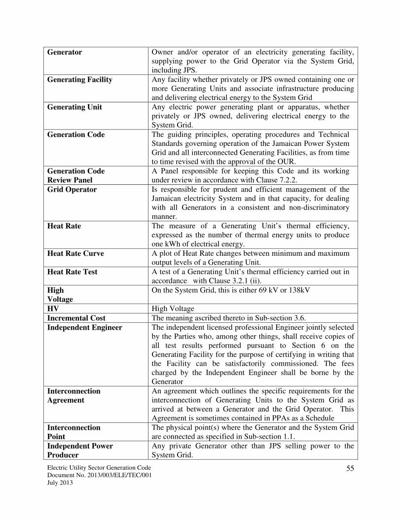
Electric Utility Sector Generation Code Document No. 2013/003/ELE/TEC/001 July 2013
55
Generator Owner and/or operator of an electricity generating facility, supplying power to the Grid Operator via the System Grid, including JPS.
Generating Facility Any facility whether privately or JPS owned containing one or more Generating Units and associate infrastructure producing and delivering electrical energy to the System Grid
Generating Unit Any electric power generating plant or apparatus, whether privately or JPS owned, delivering electrical energy to the System Grid.
Generation Code The guiding principles, operating procedures and Technical Standards governing operation of the Jamaican Power System Grid and all interconnected Generating Facilities, as from time to time revised with the approval of the OUR.
Generation Code
Review Panel
A Panel responsible for keeping this Code and its working under review in accordance with Clause 7.2.2.
Grid Operator Is responsible for prudent and efficient management of the Jamaican electricity System and in that capacity, for dealing with all Generators in a consistent and non-discriminatory manner.
Heat Rate The measure of a Generating Unit’s thermal efficiency, expressed as the number of thermal energy units to produce one kWh of electrical energy.
Heat Rate Curve A plot of Heat Rate changes between minimum and maximum output levels of a Generating Unit.
Heat Rate Test A test of a Generating Unit’s thermal efficiency carried out in accordance with Clause 3.2.1 (ii).
High
Voltage
On the System Grid, this is either 69 kV or 138kV
HV High Voltage
Incremental Cost The meaning ascribed thereto in Sub-section 3.6.
Independent Engineer The independent licensed professional Engineer jointly selected by the Parties who, among other things, shall receive copies of all test results performed pursuant to Section 6 on the Generating Facility for the purpose of certifying in writing that the Facility can be satisfactorily commissioned. The fees charged by the Independent Engineer shall be borne by the Generator
Interconnection
Agreement
An agreement which outlines the specific requirements for the interconnection of Generating Units to the System Grid as arrived at between a Generator and the Grid Operator. This Agreement is sometimes contained in PPAs as a Schedule
Interconnection
Point
The physical point(s) where the Generator and the System Grid are connected as specified in Sub-section 1.1.
Independent Power
Producer
Any private Generator other than JPS selling power to the System Grid.

Electric Utility Sector Generation Code Document No. 2013/003/ELE/TEC/001 July 2013
56
IPP Independent Power Producer
JPS Jamaica Public Service Company Limited
kW Kilowatts.
kWh Kilowatt hours.
Load Demand in watts or multiples thereof.
Low Voltage On the System Grid voltage of 24 kV or less
Load Shedding The automatic or manual disconnection or interruption of the electrical supply to a customer Load by the utility, usually to mitigate the effects of generating Capacity deficiencies or transmission limitations.
LV Low Voltage.
Maintenance Outage An interruption or reduction of the Generating Unit capability that:
i. is not a Scheduled Outage; or ii. has been scheduled and allowed by the Grid Operator in
accordance with Section 5; and iii. is for the purpose of performing work on specific
components, which work could be postponed by at least six (6) Days but not be postponed until the Scheduled Outage.
Merit Order The ranking of Generating Units in the order of Variable Operating Cost. It is used as the basis for committing Generating Units into operation. The Generating Unit with the least Variable Operating Costs is ranked first; the Generating Unit with the next lowest variable operating costs is ranked second and so forth.
Metering System All meters and metering devices (including the Primary and Backup Metering Systems) used to measure the delivery and receipt of Net Energy Output, Dependable Capacity and other parameters pursuant to Section 2 of this Code.
Month A calendar Month according to the Gregorian calendar beginning at 00:00 hours Eastern Standard Time on the last day of the preceding Month and ending at 00:00 hours Eastern Standard Time on the last day of that Month.
MVA Megavolts Amperes
MVAR Megavolt Amperes reactive.
MW Megawatts.
MWh Megawatt hours.
Net Energy Output Net energy delivered by the Generator for sale to the Grid Operator at the Interconnection Point in accordance with a valid Dispatch Instruction.
Nominal Operating Voltage Voltage that is required electrically at any point of the System Grid
Non-Dispatchable
Generating Units
Generating Units will be classed as Non-Dispatchable when it is not practical to control or dictate the required level of output

Electric Utility Sector Generation Code Document No. 2013/003/ELE/TEC/001 July 2013
57
of these units to the System Grid on an ongoing basis.
Non-Spinning Reserve That reserve in MW not connected to the System but capable of serving Demand within a specified time.
Operating Reserve Generating capability in MW above firm System Demand available to provide for regulation, load forecasting error, equipment forced and scheduled outage. It consists of Spinning and Non Spinning Reserve.
Operations Log A record of significant operating events, plans, requests and instructions.
OUR Office of Utilities Regulation. The Regulatory Authority for Jamaica’s utility sector
Partial Load Rejection The partial or complete loss of power consumers without the separation of a generating unit from the grid with the generating unit initially operating at full load
Parties System Grid Operator and Generator
Party System Grid Operator or Generator
Peak Hours The hours between 5:00 pm and 9:00 pm Eastern Standard Time every day of the week.
Power Factor (pf) Ratio of Megawatt output to corresponding MVA.
Power Purchase Agreement
(PPA)
An agreement between a Generator and the Grid Operator which defines the technical, commercial and legal terms of the arrangements related to the power interchange between the entities.
Primary Metering
System
All meters and metering devices (financed by the Generator but owned by the Grid Operator) used to measure the delivery and receipt of Net Energy Output, Dependable Capacity and other parameters pursuant to Section 2 of this Code.
Prudent Utility
Practice The practices generally followed by the electric utility industry in respect to the design, construction, operation, and maintenance of electric generating, transmission, and distribution facilities, including, but not limited to, the engineering, operating, and safety practices generally followed by such utility industries.
Qualifying Entity or QE a residential or non-residential entity which is the legal owner of the QF
Qualifying Facility or QF an approved intermittent renewable energy system with nameplate capacity less than or equal to 100 kW
Rapid Start The ability for a generating set to be started and synchronized in less than 10 minutes after an instruction is given to do so by the grid operator.
Rated Capacity A measure of the ability to generate electric power continuously usually expressed in Megawatts or kilo Watts.
Reactive Power The Wattless component of the product of voltage and current, which the Generating Unit shall provide to or absorb from the System Grid and which is measured in MVAR.

Electric Utility Sector Generation Code Document No. 2013/003/ELE/TEC/001 July 2013
58
Rural Area Area of Jamaica that does not fall within the Corporate Area
Scheduled Outage A planned interruption of the Generator's generating capability that:
i. is not a Maintenance Outage; ii. has been scheduled and allowed by the Grid Operator in
accordance with Section 5; and iii. is for inspection, testing, preventive maintenance,
corrective maintenance or improvement.
Spinning Reserve Unloaded generating capacity in MW which is synchronized and ready to serve additional Demand.
Sequence of Events Record of power system activities with respect to time.
Substation Grouping of equipment inclusive of transformers, circuit breakers, switches and protective devices used to facilitate among other things the transformation of voltages and switching operations. A combination of generation, transmission, and distribution components within a specially defined area.
System Control
Center The System Control Center located in Kingston, Jamaica, or such other control center designated by the Grid Operator from time to time (but not more than one at any time) from which the Grid Operator shall issue Dispatch instructions to the Generators.
System Control Engineer
Person appointed by the Grid Operator and on duty at System Control Center with responsibility for controlling the generation, transmission and distribution of electrical energy.
System Emergency A condition or situation that, materially and adversely, or is likely to materially and adversely; (i) affect the ability of the Grid Operator to maintain safe, adequate and continuous electrical service to its customers, or (ii) endanger the security of person, plant or equipment.
System Grid The Interconnection Facilities and any other transmission or distribution facilities on the Grid Operator' side of the Interconnection Point(s) through which the electrical energy output from the Generating Unit(s) will be distributed by the Grid Operator to users of electricity.
Synchronization The controlled interconnection of System facilities to operate in phase at the same frequency and voltage.
Technical Standards All standards as outlined in Clause 1.2.1 or any other acceptable benchmark or method as defined or in use by the Grid Operator.
Ten Minutes Reserve An additional amount of operating reserve sufficient to reduce generation deficiency within ten minutes following the loss of generating capacity;
Transmission System That section of the System Grid between the Generator interconnection point and the HV side of the Distribution Substation. This System is operated at 69 kV and 138 kV.

Electric Utility Sector Generation Code Document No. 2013/003/ELE/TEC/001 July 2013
59
Unit Controller Person designated by the Generator to oversee the operation of any of the Generating Units and to liaise with System Control Engineer in this process.
Unit Commitment Schedule
The sequence of startup and shutdown time of thermal Generating Units which minimizes the total production cost including startup and shutdown costs over a period of at least 24 hours or up to a week, given the load forecast, and taking into account the Maintenance Schedule, generation reserve requirement and System security.
Variable Operating Cost Costs that vary with production of electricity.
VOM Variable Operation and Maintenance cost
Week A period of seven (7) consecutive Days beginning at 00:00 hours Eastern Standard Time falling between a Saturday and a Sunday.
Year Each twelve (12) Month period commencing on 00:00 hours Eastern Standard Time on December 31 and ending on 00:00 hours Eastern Standard Time the following December 31 during the term of this Code.

Electric Utility Sector Generation Code Document No. 2013/003/ELE/TEC/001 July 2013
60
SCHEDULE B: REQUIRED COMMUNICATION EQUIPMENT The Communication Systems used for System Operations are in two basic forms –VHF
Radio for general operational communications (including mobile units), and a point-to-
point telephone system for Substations and Generating Stations operation. For switching
operations, the primary form of communication is radio while the secondary
communication is telephone. For all other operations, telephone is the primary form of
communication and radio is the secondary form. Proper use of these facilities is described
in detail in the Grid Operator’s Policies and Procedures Manual for System Operation.
However the following principles are especially noteworthy:
� The VHF radio system should be operated in accordance with stipulated protocols.
� Transmitter/receiver sets are located at all District offices, Power Stations, major
Substations and in the Generator’s Operating vehicles
� Communication equipment should be properly maintained and any malfunction of
such equipment be reported to System control promptly
� In the event of loss of communication (including Public Telephone facilities) between
a generating station and System Control, the Generator’s management must assume
full direction and control of the Station. All actions taken and their corresponding
times must be logged and reported to system control as soon as communication is
restored. In any such event the first priority is safety and then system integrity. The
Generator shall not change the operations and shall maintain the last dispatch while
maintaining safety.
SUPERVISORY CONTROL AND DATA ACQUISITION
The Supervisory Control And Data Acquisition (SCADA) System is currently used to
monitor and record status and analogue values at relevant data collection points
throughout the system. Required points for monitoring include circuit breakers, switches,
potential transformers and current transformers.
The SCADA system performs constant scanning of all data points and logs a status
update every two seconds, unless a significant non-transient change occurs that results in
a monitored value exceeding its predefined limits, in which case the resolution of the data
recorded is in milliseconds. It is therefore necessary that the monitoring/control devices

Electric Utility Sector Generation Code Document No. 2013/003/ELE/TEC/001 July 2013
61
installed at the Generating Station be capable of sub second response to a degree equal to
or better than that of the System’s SCADA equipment.
REQUIRED COMMUNICATION EQUIPMENT
Each Generator shall install and maintain at each Generating Station at its sole cost and
expense:
i) Compatible Remote Terminal Units (“RTUs”) to allow interfacing of SCADA
status and analog signals from the generating station to the centralized SCADA
system at system control, specifically transmitting:
a) Three phase values of watts, vars, voltage, and current as well as busbar
frequency
b) Status (open, closed) of the relevant circuit breakers
ii) Adequate Power Line Carrier Channels to System Control Centre for the purpose
of tele-metering, protection and telecommunications.
iii) An extension of System Control Centre PBX System in the Generating Units
control room to facilitate (hotline) voice communication between the Generator
control room and System Control Centre.
iv) Telecommunications facilities such as Internet and landline telephones in the
Generating Units control room to transmit and receive telecopies/facsimiles and
electronic mail to and from System Control Centre respectively.
v) UHF and VHF radio equipment to permit voice communication between the
Generating Unit control room and System Control Centre.
vi) Microwave equipment to transmit data to System Control Centre.
vii) A synchronized digital GPS Clock to allow time stamping of all analog and status
communications especially those logged by the Sequence of Events recorder.
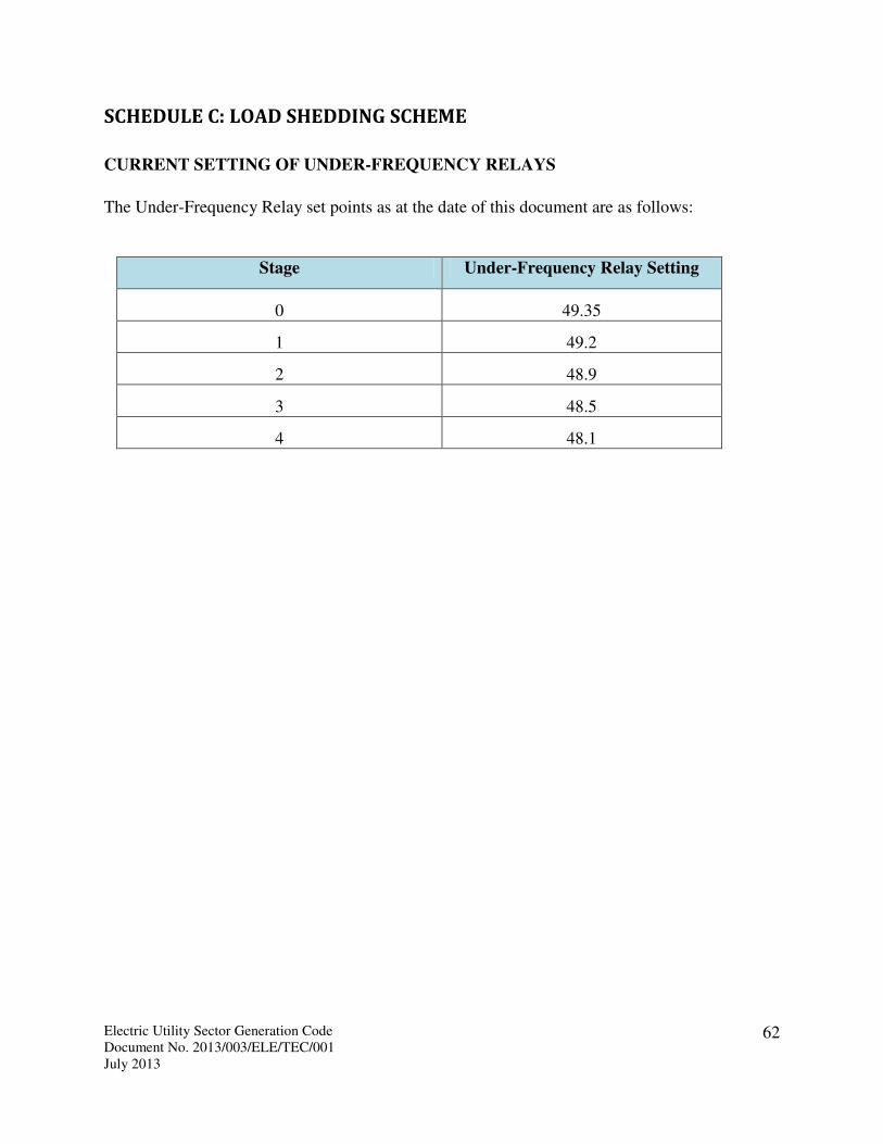
Electric Utility Sector Generation Code Document No. 2013/003/ELE/TEC/001 July 2013
62
SCHEDULE C: LOAD SHEDDING SCHEME
CURRENT SETTING OF UNDER-FREQUENCY RELAYS
The Under-Frequency Relay set points as at the date of this document are as follows:
Stage Under-Frequency Relay Setting
0 49.35
1 49.2
2 48.9
3 48.5
4 48.1

Electric Utility Sector Generation Code Document No. 2013/003/ELE/TEC/001 July 2013
63
SCHEDULE D: RESERVE MARGIN POLICY
SPINNING RESERVE POLICY:

Electric Utility Sector Generation Code Document No. 2013/003/ELE/TEC/001 July 2013
64
SCHEDULE E: EXISTING GENERATING SYSTEM
Unit Capacity
(MW)
Technology Fuel
Type
Location Remarks
RF#1 20.0 Slow Speed Diesel HFO Rockfort
RF#2 20.0 Slow Speed Diesel HFO Rockfort
OH#1 30.0 Steam HFO Old Harbour Out of service
OH#2 60.0 Steam HFO Old Harbour
OH#3 65.0 Steam HFO Old Harbour
OH#4 68.5 Steam HFO Old Harbour
HB#B6 68.5 Steam HFO Hunt’s Bay
GT#5 21.5 ADO Fired Gas Turbine ADO Hunt’s Bay
GT#10 32.5 ADO Fired Gas Turbine ADO Hunt’s Bay
GT#3 21.5 ADO Fired Gas Turbine ADO Bogue
GT#6 14.0 ADO Fired Gas Turbine ADO Bogue
GT#7 14.0 ADO Fired Gas Turbine ADO Bogue
GT#8 14.0 ADO Fired Gas Turbine ADO Bogue
GT#9 20.0 ADO Fired Gas Turbine ADO Bogue
GT#11 20.0 ADO Fired Gas Turbine ADO Bogue
Bogue Combined Cycle 114.0 ADO-CCGT ADO Bogue
Maggotty 6.0 Run of River Hydro Maggotty
Lower White River 4.75 Run of River Hydro White River
Upper White River 3.19 Run of River Hydro White River
Roaring River 4.05 Run of River Hydro Roaring River
Rio Bueno "A" 2.5 Run of River Hydro Rio Bueno
Rio Bueno "B" 1.1 Run of River Hydro Rio Bueno
Constant Spring Hydro 0.75 Run of River Hydro Constant Spring
JPPC - IPP 60.0 Slow Speed Diesel HFO Rockfort
JEP - IPP 124.2 Medium Speed Diesel HFO Old Harbour
WKPP - IPP 65.5 Medium Speed Diesel HFO Hunts Bay
Wigton Wind Farm I 20.7 Wind Turbines Wigton Energy only
Wigton Wind Farm II 18.0 Wind Turbines Wigton Energy only
Munro College 0.25 Wind Turbine Munro
JPS Munro Wind 3.0 Wind Turbines Munro
Jamaica Broilers as-available Slow Speed Diesel HFO Spring Village
JAMALCO 11.0 Steam - Cogen HFO May Pen
JAMALCO as-available Alternative St Jago, Clarendon ADO Automotive Diesel Oil GT Gas Turbine HB Hunts Bay HFO Heavy Fuel Oil IPP Independent Power Producer JEP Jamaica Energy Partners JPPC Jamaica Private Power Company OH Old Harbour RF Rockfort WKPP West Kingston Power Partners

Electric Utility Sector Generation Code Document No. 2013/003/ELE/TEC/001 July 2013
65
LAYOUT OF JAMAICA’S GENERATION AND TRANSMISSION SYSTEMS

Electric Utility Sector Generation Code Document No. 2013/003/ELE/TEC/001 July 2013
66
SCHEDULE F: GRID OPERATOR INTERCONNECTION CRITERIA
GENERATING UNIT(S) CONNECTED TO THE JAMAICAN TRANSMISSION SYSTEM
Category System Operations
Criteria/Parameters
Plant/Generator Design
Criteria
Comments Generation/
Transmission
Code Ref.
Transmission
System Security
Interconnection
Voltage
Generating Unit(s) at rated
capacity >10MW shall be
connected to the Transmission
system at 69kV or 138kV.
The Grid Operator on the
basis of System Security,
Stability and Safety shall
determine the
interconnection voltage.
GC 1.1.2
Reliability of
Generating Unit(s)
Grid Connection
Points
All substations shall have the
capability to disconnect or
separate, from the System Grid,
any transmission line and/or
generating unit that is
interconnected to the substation.
Substations (including
Generation substations) with
more than three (3)
transmission lines or generating
units shall be of a “breaker and a
half configuration”.
GC 1.1.3
Loss of Generation For the loss of one transmission
element there shall be no loss of
generation > 60MW.
The loss of any single
transmission element
connecting a generating unit(s)
shall not result in a loss of
generation greater than 60MW.
Therefore generation greater
than 60MW shall be designed on
the N-1 principle.
GC 1.1.1

Electric Utility Sector Generation Code Document No. 2013/003/ELE/TEC/001 July 2013
67
Category Operations
Mode
Unit System Operations
Criteria/
Parameters
Plant/Generator Design Criteria Comments Code Ref.
Plant
Performance
Frequency Nominal Hz 50 Generating plant and auxiliary
apparatus shall be designed to operate
at this nominal frequency (continuous
operation).
Intermittent and/or renewable
type generating plant shall
maintain active power output as
per the turbine/generator
power curve characteristics.
GC – Sect.
1.2.2
Normal
Operating
Band
Hz 49.5 – 50.5 Maintain constant Active Power output
at any load point. Generating plant and
auxiliary apparatus shall be designed to
operate in this range.
GC – Sect.
1.2.2
Abnormal Hz 48.5 – 49.5
50.5 – 52.5
Maintain constant Active Power output
at any load point. Plant and Apparatus
shall be designed to operate in this
range (continuous operation)
Intermittent and/or renewable
type generating plant shall
define the limitations of
generating unit(s) to meet these
criteria for review and approval
by the Grid Operator.
GC – Sect.
1.2.2
Hz 48.0 – 48.5 Maintain, for at least one (1) second,
Active Power within 95% and 100% of
output loading levels before abnormal
frequencies occurred. Generating plant
and auxiliary apparatus shall be
designed to operate in this range.
Hz <48.0 Generator trip settings shall be as
agreed with the Grid Operator.
Voltage Nominal KV 69kV or 138kV Reactive power output shall be fully
available under steady state conditions.
GC – Sect.
1.3
Normal
Operating
Band
(± nominal
kV)
% ± 5% Reactive power output shall be fully
available under steady state conditions
(continuous operation). The Generating
Unit shall not be affected by voltage
changes in this operating band.
Generating plant requiring
reactive power support (e.g.
induction generators) shall
provide their full reactive
power
compensation within the
specified voltage operating
bands (normal and abnormal)
GC – Sect.
1.3
Abnormal % ± 10% Reactive power output shall be fully
available under steady state conditions

Electric Utility Sector Generation Code Document No. 2013/003/ELE/TEC/001 July 2013
68
Category Operations
Mode
Unit System Operations
Criteria/
Parameters
Plant/Generator Design Criteria Comments Code Ref.
(continuous operation) as per the
capability curve of the plant. The Unit(s)
and auxiliaries shall not lose
synchronism or trip by voltage changes
in this operating band.
Voltage Dips
(Fault Ride
Through
Capability)
Abnormal % of
nominal
bus kV
10% to 90% VOLTAGE DIPS OF DURATION ≤
120ms
The generating unit(s) shall remain
stable and connected to the system
without tripping or losing synchronism
for transmission voltage dips less than
or equal to 120ms in duration.
See FIGURE A for Low Voltage
Ride Through (LVRT) Curve.
VOLTAGE DIPS OF DURATION >
120ms
For transmission voltage dips occurring
due to system disturbances greater than
120ms (6 cycles) in duration the
generating unit(s) shall:
During Voltage Dip
1. Remain transiently stable and
connected to the system for at least 1
second without tripping/losing
synchronism.
2. Provide Active Power output during
voltage dips at least in proportion to
the retained balanced voltage at the
Interconnection Point.
Immediately After Voltage Dip
3. Restore Active Power output at the
Interconnection Point to 90% of
nominal levels (available
immediately before the occurrence of
the dip) within 1 second of
restoration of steady state voltage
conditions. That is, within the normal
voltage operating band of 69kV ± 5%

Electric Utility Sector Generation Code Document No. 2013/003/ELE/TEC/001 July 2013
69
Category Operations
Mode
Unit System Operations
Criteria/
Parameters
Plant/Generator Design Criteria Comments Code Ref.
Negative
Phase -
Sequence
Component of
phase voltage
Normal % <1% Sustained operation at any load
(continuous operation)
(Unbalance
loading
withstand
capability)
abnormal % ≤2% Sustained operation at any load
(continuous operation)
Negative
Phase -
Sequence
Component of
phase voltage
cont’d
(Unbalance
loading
withstand
capability)
faults Generating unit shall withstand, without
tripping, the negative phase sequence
loading incurred by clearance of a close-
up phase-to-phase fault by system back-
up protection on the Transmission
System.
The Grid Operator shall provide
relay settings upon request.
Plant Output Normal MW Rated Generating
Unit output shall be
provided in the
Interconnection or
Power Purchase
Agreement.
Supply rated Active Power (MW) at any
point between limits 0.85 pf lagging and
0.95 pf leading at generator terminals.
Reactive power output shall be fully
variable between these limits.
Intermittent and/or renewable
type generating plant shall
maintain Active Power (MW)
output as per the
turbine/generator power curve
characteristics.
Synchronisati
on
Normal 1. Synchronise and parallel/load
transfer with grid without
causing voltage fluctuation at
Interconnection Point >±5% of
voltage at Interconnection
Point.
2. Synchronise to Grid within
voltage ±5% of nominal and
frequency 50±0.5Hz
Abnormal Synchronise to Grid within voltage

Electric Utility Sector Generation Code Document No. 2013/003/ELE/TEC/001 July 2013
70
Category Operations
Mode
Unit System Operations
Criteria/
Parameters
Plant/Generator Design Criteria Comments Code Ref.
±10% of nominal and frequency
50±0.5Hz
Controls
Frequency
Control
Normal Each generating unit shall be capable of
contributing to frequency control by
continuous modulation of Active Power
supplied to the Transmission system.
The unit shall be fitted with a fast-acting
speed governing system that shall have
an overall speed droop characteristic of
five (5) percent or less.
The speed governor deadband shall be
no greater than 0.1 Hz.
Applicable on a Case-by-Case
basis for intermittent and/or
renewable type generating
plant.
The droop setting shall be 5%.
Voltage
Control
Normal Each generating unit shall be capable of
contributing to voltage control by
continuous changes to the Reactive
Power supplied to the Transmission
system.
Automatic Voltage Regulator:
Deadband: not exceeding 0.5%
Controls: Capability to control voltage
continuously between 90% and upper
limit of rated voltage of the generator
from no load to full load. This range
shall be covered linearly in
approximately 1 minute.
Applicable on a Case-by-Case
basis for intermittent and/or
renewable type generating
plant.
Excitation
Control
Excitation
Control
(cont’d)
Normal
Normal
Provide Constant Terminal voltage
control of the synchronous generating
unit without instability over the entire
operating range of the unit
Excitation System (Large Signal
Response):
Voltage Response Time: less than 0.1
Applicable on a Case-by-Case
basis for intermittent and/or
renewable type generating
plant.

Electric Utility Sector Generation Code Document No. 2013/003/ELE/TEC/001 July 2013
71
Category Operations
Mode
Unit System Operations
Criteria/
Parameters
Plant/Generator Design Criteria Comments Code Ref.
second for a voltage step change not to
exceed 5% in terminal voltage
Ceiling Voltage: minimum 160% of
generator rated load field voltage.
Protection
Generator
Protection
Abnormal Protect against:
• Loss of
Excitation
• Under
Excitation
• Unbalanced
Load Operation
• Stator Phase
Faults and Earth
Faults
• Reverse Power
• Unit Over and
Underfrequency
• Thermal
Overload: Stator
Over
Temperature,
• Generator
Overspeed
• Restricted Earth
Fault
Meet system protection requirements
for all synchronous generating units.
Protection requirements for
asynchronous generators to be
reviewed and approved by the
Grid Operator.
GC – Sect.
1.2.4
Generating
Unit Step Up
Transformer
(GSU)
Protect against:
• Phase and earth
faults (HV and
LV) within the
GSU zone
• Transformer
Tank Sudden
pressure,
• Differential
Current
• Backup
protection if
Meet system protection requirements
for all GSU.

Electric Utility Sector Generation Code Document No. 2013/003/ELE/TEC/001 July 2013
72
Category Operations
Mode
Unit System Operations
Criteria/
Parameters
Plant/Generator Design Criteria Comments Code Ref.
failure of the
plant local
breaker to
operate
o The plant owner
to provide
breaker fail
signal to Grid
Operator
switchyard
Interconnecti
on Protection
Abnormal Protect against:
• Phase and
Earth Faults
(tie-lines, bus)
• Failure of Grid
Operator (JPS)
remote
protection to
clear grid
phase and
earth faults
(b/up
protection)
oGrid Operator
(JPS) to
provide
breaker fail
signal to
generator
owner
switchyard
• Failure of plant
local breaker
to operate
(breaker fail
Meet system protection requirements at
Interconnection Point.
Protective system to be applied
at the Interconnection Point
shall be designed, coordinated
and tested to achieve speed,
sensitivity and selectivity in
fault clearing. Relay types to be
approved by the Grid Operator
(JPS).

Electric Utility Sector Generation Code Document No. 2013/003/ELE/TEC/001 July 2013
73
Category Operations
Mode
Unit System Operations
Criteria/
Parameters
Plant/Generator Design Criteria Comments Code Ref.
protection)
oThe generator
owner to
provide
breaker fail
signal to Grid
Operator
(JPS)
switchyard
Fault Clearing
Times
Transmission
bus
(point of grid
interconnect-
ion)
Maximum
time
Milli-
seconds
(ms)
To be provided in
Power Purchase
Agreement (PPA)
documents.
In the absence of the
requirement in PPA
documents, fault
clearing time (from
fault inception to arc
extinction) shall not
be slower than:
69kV – 120ms
138kV – 100 ms
Meet or exceed system fault clearing
times. The generating unit shall remain
transiently stable and connected to the
system without tripping for a close-up
solid three phase fault or any
unbalanced short circuit fault on the
Transmission System up to the
maximum total fault clearance time.
During the period of the fault the
generating unit shall generate maximum
reactive current without exceeding the
transient rating limit of the generating
unit.
Fault Levels Transmission
bus
(point of grid
interconnect-
ion)
Amps (A) To be provided in
Power Purchase
Agreement (PPA)
documents.
The maximum fault levels at the grid
Interconnection Point shall be below
80% of the interrupting capacity of
substation and plant apparatus
determined using generator transient
impedances.

Electric Utility Sector Generation Code Document No. 2013/003/ELE/TEC/001 July 2013
74
The owner of the Generating Unit(s) is required to submit to the Grid Operator all Generating Unit and Generating Unit Step-
Up (GSU) transformer parameters upon completion of plant, apparatus and equipment designs.

Electric Utility Sector Generation Code Document No. 2013/003/ELE/TEC/001 July 2013
75
FIGURE A: Low Voltage Ride-Through (LVRT) Curve
Generating Units must remain connected to the grid in the region above the Low Voltage Ride-Through (LVRT) curve.
JPS LVRT Requirement
1.120.12
0
0.1
0.2
0.3
0.4
0.5
0.6
0.7
0.8
0.9
1
1.1
-0.3 -0.2 -0.1 0 0.1 0.2 0.3 0.4 0.5 0.6 0.7 0.8 0.9 1 1.1 1.2 1.3 1.4 1.5 1.6 1.7 1.8 1.9 2 2.1 2.2 2.3 2.4
Time (s)
Vo
lta
ge
(p
u)
Voltage (pu)
UNITS MUST
REMAIN
CONNECTED TO
THE GRID UNITS NOT REQUIRED TO REMAIN
CONNECTED TO THE GRID