j u.s. department circular - federal aviation … by inspecting the fuel system fillers and...
TRANSCRIPT
J U.S. Department ot Transportation FodomlAvianon Circular
Subject: RECIPROCATING ENGINE POWER- Date: 6/15/98 AC No: 20-105B LOSS ACCIDENT PREVENTION AND TREND MONITORING
Initiated by: AFS-340 Change:
1. PURPOSE. This advisory circular (AC) updates statistical information and brings to the attention of aircraft owners, operators, manufacturers, and maintenance personnel the circumstances surrounding engine power-loss accidents with recommendations on how, through individual effort and consideration, those accidents can be prevented. This AC will also offer procedures on how to set up a reciprocating engine trend monitoring program to improve both engine and related system reliability over the recommended operating life of the engine.
2. CANCELLATION. AC 20-105A, Engine Power-Loss Accident Prevention, dated November 20, 1980, is canceled.
3. BACKGROUND. Four and six cylinder reciprocating engines presently installed in Civil
’ Aviation Regulation (CAR) 3 and Title 14 of the Code of Federal Regulations (14 CFR) part 23 type-certificated aircraft are the engine of choice for small single engine and multi-engine aircraft because of their reliability. The recommended time between overhaul (TBO) for reciprocating engines range between 1500/l 800 hours for high performance six cylinder engines to 2000 hours for low compression 4 cylinder engines. Despite improvements over the years, in engine design and performance, a review of National Transportation Safety Board (NTSB) reciprocating engine failure accident records covering a three year period from 1994 through 1996, revealed that the overall causes of reciprocating engine failures remain the same as the early 1960’s.
a. Of the 1,007 accidents analyzed, 5 18 or 5 1% of the accidents were attributed to pilot error, such as poor preflight planning, inspection, or improper use of engine controls. Three hundred and two accidents or 30% were attributed to mechanical failure such as valve or cylinder failure, and the remaining 187 accidents or 19% were attributed to improper maintenance and/or inspection of the aircraft. It is the Federal Aviation Administration’s (FAA) belief that approximately 70% of these engine power loss accidents could have been avoided if the owner/operator instituted an aggressive training program for pilots and mechanics and incorporated a trend monitoring program.
b. This AC is divided into two major sections. The first section will review operational causes and recommend corrective actions to be taken to prevent or reduce the chances for an engine failure. The second section presents and explains a sample program for engine trend monitoring system. A

AC 20-105B 6/l 5198 4. DISCUSSION OF OPERATIONAL ENGINE FAILURES.
a. Lack Of Pilot Training. Mismanagement of engine control system(s) by the pilot continues to be the leading cause of engine failure. Most of these types of failures result from improper preflight planning or improper fuel management procedures. Fuel starvation (fuel on board the aircraft but not supplied to the engine(s), and fuel exhaustion (no fuel on board the . aircraft) account for over 5 1% of all engine power-loss accidents. Pilots and operators should review their aircraft’s fuel and engine system operating requirements to ensure that:
(1) The pilot is completely familiar with both the airframe and engine operating manuals, especially the chapters concerning fuel management, engine power settings, use of carburetor heat and each of the aircraft’s systems design, locations, and controls.
(2) The pilot adheres to all manufacturer’s operating instructions, placards, and other limitations and avoids overtemp, overheat, overboost, and overspeed operations.
(3) The use of the aircraft’s checklist during normal and emergency operations is stressed.
(4) Recurrent training is a continuing process. Both pilots and mechanics should keep abreast of technical information related to the aircraft’s fuel, oil, replacement parts, airworthiness directives, and manufacturer’s technical publications.
b. Inadequate Preflight Inspection. A large number of engine power loss accidents could have been avoided if the pilot took the time to plan the flight and performed a good preflight. Each year the accident records show a high number of accidents that were caused by pilots running out of fuel. For good flight planning the pilot should include at least the following information in his or her pre-flight check list.
(1) Pilots should know the total USABLE fuel on board the aircraft before each flight. The UNUSABLE fuel (fuel in the tanks but due to design of the tank, cannot be used by the engine(s)) should not be considered as usable fuel when planning a flight.
(2) Check each fuel tank drain for operation. Check for water or debris in the fuel. Also check the color of the fuel to ensure that Jet A has not been mixed with Aviation gasoline (Av- kw).
(3) Check the under wing fuel tank vents to ensure that they are open. In the early spring and summer months you might want to use a pipe cleaner as a probe to ensure that insects have not built a nest in the vent line. Also on unpressured tanks, the fuel cap has a small vent built into it, Ensure that this vent is not covered over with dirt, wax, or polish.
(4) Ensure that the fuel selector works as advertised. A number of engine power loss accidents were caused by the pilot who was unable to move the seized fuel tank selector handle from the empty tank to the full one, or failed to lock the fuel tank selector into the proper detent. These mechanical problems are usually caused by a worn or galled fuel selector valve.
Page 2 Par4
6/l S/98 AC 20-105B To prevent fuel selector failure prior to taxi, exercise the selector valve by switching tanks and ensuring that there is fuel flow from each selected tank to the engine(s). Remember to allow sufficient time (3 to 4 minutes) for each check as the carburetor/fuel injector lines hold fuel from the previous selected tank. Do not forget to monitor the fuel pump pressure. At least once a month, check thatme fuel selector’s fuel shut off position to ensure it will stop the fuel flow to the engine. Remember it will take a few minutes at low RPM setting for the engine to drain the fuel from the fuel lines/carburetor/fuel injector and cause the engine to quit. This check is very important because in case of an engine fire, the fuel shut off valve will stop fuel flow on the cabin side of the fire wall, effectively preventing an engine fire from being fed from the aircraft fuel tanks. If a worn or galled fuel selector is suspected, have a mechanic lubricate or replace the valve, as needed.
c. Fuel Contamination. There are two basic kinds of fuel contamination, solid and water. Solid contaminates, such as sand, rust, and other debris can be found by inspecting the low areas/sumps of each (empty and properly purged) fuel tank with an explosion proof flashlight, and by inspecting the fuel system fillers and carburetor/injector in-line filter screen for solid particulate contamination. If solid particle contamination continues to occur on a frequent basics, the primary fuel supplier may be the source of the problem.
(1) Water contamination continues to be a major cause of fuel related accidents. There are three ways water can enter a fuel system. The first is condensation, or the reduction process in which the moisture in warm air is reduced into liquid water. This phenomenon is exactly what causes windows in a warm house to “sweat” during the winter months. In an aircraft, condensation can happen inside a less than full fuel tank. When a temperature difference occurs between the walls of the fuel tank and the air in the tank, water droplets will form on the inside top part of the fuel tank walls and drain down into the fuel. The effects of condensation can be reduced by keeping the fuel tanks full while the aircraft is parked.
(2) The second way water gains access to the fuel system is through the fuel filler caps. Rain water or snow runoff entry into the fuel system is made easier if the fuel filler caps have cracked or nicked “0” rings, scored, or deformed filler necks. Many high performance general aviation aircraft have flush mounted fuel caps that have at least two “0” rings. The most visible “0” ring is the one on the circumference of the fuel cap that provides the seal between the cap and the filler neck wall. The second “0” ring is frequently overlooked by both mechanics and pilots and is located in the center of the cap and seals the fuel cap lock assembly. Because of the design, the fuel cap lock sits in a well in the center of the fuel cap. The well provides a catch basin for water runoff. If the smaller “0” ring is defective, water will find a way into the tank. This potential hazard can be avoided by an aggressive filler neck/cap inspection and “0” ring replacement schedule.
(3) The third way water can enter a fuel system is when it is refueled. Careless fuel dispensing practices such as refueling when it is raining, or poor maintenance of the fuel truck/fuel farm, filters, water separators, or lack of adequate inspections or dispensing procedures are generally the causal factors. To prevent dispensing contaminated fuel, fixed base operators
, (FBO) should ensure that their fuel handling personnel are adequately trained, the fuel dispensing equipment is functional and clean, the fuel, both in the storage tanks and trucks are checked at
Par4 Page 3
AC 20-105B 6/l S/98 least once a day for overall quality and indications of water or other contaminates. Each inspection should be documented. (See AC 20-125, Water in Aviation Fuels, for additional information.)
d. Misfueling Accidents. This occurs when Jet A, a turbine engine fuel is substituted for aviation gasoline. When Jet A contaminates a reciprocating engine powered aircraft’s fuel system the overall impact is not readily apparent. Depending on the amount of Jet A pumped into the aircraft fuel tank, even a close inspection of a fuel sample may not always indicate misfueling has occurred. Even the engine start up and taxi may appear to be normal because the Av-gas, that is still in the fuel supply system line and filters from the last flight is not contaminated and it usually takes the engine a few minutes at relatively high power settings to draw contaminated fuel from the selected tank. This is why a large number of misfueling accidents occurs at high power setting usually during or shortly after takeoff.
(1) Reciprocating engines that burn Jet A at high power settings, suffer detonations, rapid loss of power, and high cylinder head temperatures, quickly followed by complete engine failure. Switching to another uncontaminated fuel tank as soon as possible after the engine detonation occurs may relieve some of the major symptoms, and the engine may develop enough power to stiely land. Unfortunately, internal damage to the engine that occurs in the first 10 to I5 seconds is usually severe enough to require a tear-down inspection and engine rebuild. In all cases, follow the engine manufacturer’s instructions if the engine has been operated with the wrong fuel.
(2) The potential for misfueling can be reduced if the pilot personally oversees the refueling operation. The pilot should carefully check the fueling receipt for both the quantity and type of fuel added. Also check before and after refueling for clarity, color, and indication of water in the fuel. It is suggested that the aircraft’s owner/operator ensure that the fuel filler ports are properly marked with the proper type and octane of the fuel to be used, and the capacity of the tank.
, (3) It is also suggested that the owners of turbo-charged, reciprocating engine aircraft remove those decals from the cooling or fuselage that reference the words “Turbo or Turbo- Charged.” In the past, these decals have given the wrong impression to inexperienced refueling personnel that the turbo-charged reciprocating engine is a turbine engine and serviced the aircraft with Jet A (see AC 20-43, Aircraft Fuel Control, and AC 20-l 16, Marking Aircraft Fuel Filler Openings with Color Coded Decals, for additional information.)
e. Fuel Tank (Bladders). Fuel cells or bladder tanks are made of a heavy, rubberized material. The cell sits in a wing cavity designed to support the fuel tank. The top of the cell is held to the top of the wing by clips or snap buttons. Over time the snaps or clips fail and the fuel tank collapses on itself. When the tank is partially collapsed, it limits the amount of fuel that the tank can hold, interferes with fuel tank venting/supply and fuel quantity indicating system. Mechanics should inspect all fuel cells for proper installation at each annual or 100 hour inspection or whenever fuel cell clip/snap failure is suspected.
Page 4 Par4

6/l 5198 AC 20-105B f. Exceeding TBO Time. Another cause of engine failure is allowing the engine to run past
the manufacturer’s recommended Time Between Overhauls (TBO). TBO time is computed by the engine manufacturer and is a reliable estimate of the number of hours the engine could perform reliably within the established engine parameters and still not exceed the service wear limits for overhaul for major component parts such as the crankshaft, cam shaft, cylinders, connecting rods, and pistons.
(1) Running the engine past TBO time usually accelerates the overall wear of the engine due to bigger bearing tolerances, loss of protective materials such as plating or nitrating on the cylinder walls, and vibration caused by engine reciprocating parts that have worn unevenly and are now out of balance.
(2) The TBO times are make and model specific and the recommended overhaul times are usually identified in the engine manufacturer’s Service Bulletin or Letter. For 14 CFR part 91 operations compliance to the TBO time is not a mandatory maintenance requirement. However, for engines in 14 CFR part 12 1 or part 135 service TBO compliance is mandatory. It is recommended that TBO be observed by part 91 owners for two reasons: first, an overhaul at TBO will ensure safety and reliability, and the second: an engine overhaul at TBO is usually less expensive than an engine that has been run an additional 200 or 300 hours.
g. Poor Operating Technique. Reciprocating engine reliability depends on the engine operating within a narrow performance range. This operating range has specific limits such as I
RPM, fuel flow and mixture settings, manifold pressure, cylinder head temperature, oil pressure and temperature that should not be exceeded. Furthermore, all reciprocating engines are temperature sensitive. Engine cylinders and valves can be damaged by thermal shock if the engine is not properly warmed up, prior to full power applications, or the cylinder heads can crack by allowing the engine temperature to cool off too rapidly in long gliding descents at reduced power.
h. Maintenance. Maintenance performed on reciprocating engines should be of the highest quality and performed in accordance with the current manufacturer’s instructions. Areas that have the biggest impact on reliability and need constant maintenance are oil/filter changes, timely replacement of air/fuel filters, inspection of engine baffling and seals for condition and operation, engine magneto timing, and condition of the spark plugs and ignition harness. Engine maintenance should not be performed by inexperienced persons (e.g., apprentices) unless supervised by a certificated mechanic. Additional areas that require maintenance are:
(1) Engine Primer. The primer is a simple system in which raw fuel is drawn from the engine supply line and injected into two or more of the engine’s cylinders by means of a small hand operated pump. If the primer pump handle is not locked in the closed positi,on, raw fuel will continue to be drawn into the cylinders by the suction created in the affected cylinders during the intake cycle. The engine will run rough at low RPM, mimicking magneto problems, but will smooth out above 1700 RPM. The exhaust at low RPM will be black and smoky, and the fuel/air mixture will be extremely rich in the affected cylinders. Leaning the engine manually may restore smoother operation but excessive leaning will raise the cylinder head temperature in the cylinders not equipped with engine primer lines. A similar operating condition may exist if
Par4 Page 5
AC 20-105B 6/l 5198 the “0” rings in the primer pump are nicked or cracked which allows fuel to pass the “0” rings and into the cylinder even if the pump handle is stowed and locked. If this condition is suspected have a certificated mechanic check the primer system.
(2) Engine Controls. Throttle, mixture, carburetor heat, and propeller RPM controls are simple in design and construction. Each control is basica!ly a flexible metal wire inside a stainless steel housing. Due to the inherent flexibility of the design, if the cable housing is not secured at least every 12 inches, the cable will bend in the middle, severely limiting the amount of control movement available at the carburetor or propeller governor. Mechanics should ensure that the controls are lubricated, smooth and positive in operation, and that the length of cable movement ensures full travel and hits the stops. It is suggested that mechanics ensure that controls with rod ends have large area washers on both ends of the attaching bolt to serve as a safety in case of failure of the rod end ball.
(3) Propeller Ground Strikes. Any kind of a propeller ground strike is a very serious situation that requires immediate attention. Engines that have suffered a propeller strike should be inspected in accordance with the manufacturer’s instructions. Ground strikes have been known to cause crankshaft cracks, bend propeller flanges, and cause rod end bolts to fail.
(4) Internal Failures of Mufflers. Engines can experience substantial power reductions and even failure when the internal bafIling of the muffler breaks loose and partially covers over the muffler’s exhaust pipe. Indications of this kind of problem are a large reduction in RPM, rich mixture indication, rough running, vibration, and after firing. It is recommended that each annual or 100 hour, the mufIler be inspected internally for cracks and condition,
(5) Propeller Maintenance. Propellers seem to get the least attention of type-certificated products, yet they handle high thrust and torsional loads on every flight, and serve as a tow bar for parking the aircraft. Have a qualified maintenance person dress out propeller blade nicks, dents, scratches, etc., as necessary, to prevent fatigue cracks that could cause propeller blade failure resulting in power-loss. The dressing of propeller blades should be done following the propeller manufacturer’s recommended procedures. Excessive dressing could alter the airfoil shape of the propeller blades to the point where propeller efficiency is lost, causing insufficient propeller thrust. In the case of a twin engine aircraft that loss of thrust could prevent the aircraft from maintaining flight with one engine inoperative. Avoid pushing or pulling on the propeller in order to park the aircraft because the force used on the propeller to move the aircraft is not spread out over the length of the propeller but focused in a single area which may induce a stress riser (crack) on one of the blades.
(6) Sticking Valves. Engines that are hard to start, or run rough for 3 to 5 minutes after starting and then smooth out, may have one or more sticking valves. Sticking valves are caused by lead and carbon deposits in the valve guide. Over time, build up can reduce the valve stem to the guide clearance. This reduction becomes an interference fit and the valve seizes in the guide causing the push rod to bend, splitting the push rod housing and leaking oil, and loss of power for the affected cylinder. To repair a sticking valve, the cylinder must be removed and the valve guides reamed to remove the carbon and varnish deposits.
Page 6 Par4

6/l S/98 AC 20-I 05B (7) Spark Plug Fouling. Spark plugs that consistently foul can be an indication of worn
rings, excessive rich mixture, improper spark plug heat range, shortignition harness, cracked cigarettes, wrong fuel, spark plug barrels that are dirty or wet with moisture, ignition timing off, low speed open&n and idle, improper leaning procedures and rapid cool down of the engine in long gliding descents. Frequent inspection, cleaning, gapping, and rotation of the spark plugs may prove helpful in reducing fouling. Refer to the Pilot’s Operating Handbook for approved engine operating procedures.
(8) Low Cylinder Compression. A compression test is a procedure in which 80 pounds per square inch (psi) air is introduced into a cylinder with its piston at top center to determine how tight the cylinder holds the fuel/air mixture when it is compressed. The pressurized air is controlled with a differential pressure gauge that has two gauges. One gauge reads supply air, and the other gauge reads the air pressure in the cylinder. The ideal compression reading on the differentiation gauge should be 80/80 psi at top dead center. However, the maximum loss of compressed air should be no more than 25%, or a reading of 60/80 psi. If the cylinder reading is lower than 60/80 psi reading, then perform the following test. When the 80 psi compressed air is still being introduced into the cylinder, and an experienced person holding the propeller so it will not rotate, listen at the exhaust pipe outlet for an air leak. If an air leak is present, the exhaust valve or guide or both is worn and leaking. Perform the same test by listening for an air leak at the air cleaner, if you hear an air leak then the intake and/or intake valve guide is worn and leaking. To check, if the compression rings are worn, remove the oil dip stick, and listen at the oil dip stick tube. If you hear an air leak the piston rings or cylinder walls are worn. A good visual inspection of the cylinder can be accomplished by means of a borescope to check for scoring of the cylinder walls and condition of the valves and seats.
(9) Air Filters/Carburetor Heat Control, Alternate Air. Unfiltered air, whether it comes from a dirty air cleaner, carburetor heat control or alternate air door left on/open during taxi, allows dirt, sand, and other debris to be ingested by the engine and will score the cylinder walls and increase piston ring damage, causing lower compression readings and increasing oil consumption and blow-by. As a rule of thumb, air filters should be changed at least once a year, and carburetor/alternate air controls should be used sparingly on the ground.
5. TREND MONITORING PROGRAM.
a. Trend monitoring is a data collection system in which periodically a select number of engine readings/indications are recorded, analyzed, and from such data analysis an airworthiness decision is made. The purpose of a trend monitoring program is to predict a failure mode before it happens. A trend monitoring program for reciprocating engines should address at least three engine areas for monitoring. They are:
(1) Area #l . Engine case components such as crankshaft, camshaft, cam followers, lifters, bearings, connecting rods, and accessory gears are housed inside a split engine case. Because of their location, visual inspection for condition and measurement of wear of these components cannot be adequately accomplished without first disassembling the engine. The only proven effective procedures for determining the condition of this area are an oil analysis program, oil filter, and oil screen inspection.
Par4 Page 7

AC 20-105B 6/l 5198 (2) Area #2. Cylinder assembly includes the cylinder, piston and pin, intake and exhaust
valves and seats. These components can be removed for an in-depth inspection but normally an inspection of the spark plugs and a compression test will give a good overview of the cylinder’s condition. Spark plugs are checked for wear and fouling. Fouled spark plugs can indicate too rich a mixture, or compression ring wear.
(3) Area #3. Accessories including the magnetos, harness, spark plugs, exhaust, generator, or alternator drive belts, generator or alternator, carburetor/fuel injection unit and vacuum or pressure pump, are easily removable for inspection and testing and usually give the pilot an indication of their operating condition by instrumentation and gauges in the cockpit.
b. A generic trend monitoring program is found in Appendix 1 and 2. Appendix 1 is a sample data form that the mechanic and pilot will fill out. Appendix 2 is a sample tracking sheet in which all tracked items collected on the data form are listed together in sequence for easier comparison and analysis. The actual analysis of the airworthiness items should be accomplished by comparing the readings obtained and noting the trend as measured against the manufacturer’s recommended reading. For example, if the engine manufacturer recommended a cruise oil pressure of 55 to 60 psi and the indicated reading in cruise was 48 psi the mechanic should check oil viscosity, oil quantity, oil relief valve setting, oil filter, bearing wear, indications of blow by/leaks, and the accuracy of the oil pressure gauge. The mechanic can also cross check with the results of the oil analysis, cylinder head temperatures, oil temperatures, spark plug condition, and cylinder compression readings.
NOTE: A trend monitoring program is only as good as the information that it collects and analyzes. Before incorporating an engine trend monitoring program, the owner/operator should ensure that the following aircraft’s instruments and gauges have been tested for accuracy; RPM gauge, oil pressure, oil temperature, cylinder head temperature, Exhaust Gas Temperature (EGT), fuel gauges, and manifold gauge, if applicable.
c. An engine trend monitoring program is required under certain provisions of part 135 of Title 14 of the CFR. Those provisions are covered under OMB control no. 2 120-06 19.
6. SUMMARY. Through the individual and collective efforts of the aviation community, we hope to eliminate factors that have caused engine power-loss accidents. This AC is one of many efforts to try to reduce the “power loss” type of accidents. The simple act of “keeping the engine running” could appreciably reduce the number of accidents.
Thomas E. Stuckey’ ’ Acting Director, Flight Standards Services
Page 8 Par5

6/l 5198 AC 20-105B Appendix 1
APPENDIX 1. ENGINE TREND MONITORING DATA FORM
INSTRUCTIONS: Form is to be filled out by both the pilot and mechanic prior to or durjng inspection interval. Asterisk (*) items are pilot functions.
DATE OPERATOR “N” NUMBER MODEL NUMBER TOTAL TIME TOTAL TIME SINCE OVERHAUL
SIN MFG. TYPE OF OIL USED
HOBBWTACH
AREA #l ENGINE CASE COMPONENTS:
OIL ANALYSIS: DATE TAKEN LABORATORY SILICON ALUMINUM IRON
CHROMIUM COPPER
*OIL PRESSURE @ CRUISE RPM *OIL TEMPERATURE @ CRUISE RPM *STATIC RPM (FIXED PITCH) *MANIFOLD PRESSURE @ TAKEOFF OIL FILTER CONDITION:
OK
TAKE OFF RPM(CONT. PITCH)
MAGNETIC PARTICLES NONMAGNETIC PARTICLES
QUANTITY
OIL SCREEN CONDITION: OK MAGNETIC PARTICLES QUANTITY NONMAGNETIC PARTICLES QUANTITY
OIL CONSUMPTION QTS PER HOUR(S)
AREA #2 CYLINDER/PISTON ASSEMBLIES:
*CYLINDER HEAD TEMF @ CRUISE ALT +EGT @ CRUISE ALT
Page 1

AC 20-105B Appendix 1 6/l 5/98
APPENDIX 1. - continued
ENGINE COMPRESSION RESULTS: #l #2 #3 #4 #5 #6 #7 #8
SPARK PLUG CONDITION: 1 = good 2 = worn 3 = oil fouled 4 = carbon fouled
#l CYLINDER TOP BOTTOM
#2 CYLINDER TOP BOTTOM
#3 CYLINDER TOP BOTTOM
#4 CYLINDER TOP BOTTOM
#5 CYLINDER TOP BOTTOM
#6 CYLINDER TOP BOTTOM
#7 CYLINDER TOP BOTTOM
#8 CYLINDER TOP BOTTOM
*FUEL CONSUMPTION GALLONS PER HOUR @ CRUISE
*OUTSIDE AIR TEMPERATURE
Page 2

6/l 5198
APPENDIX 1. - continued
AC 20-l 05B Appendix 1
AREA #3 ACCESSORIES:
*MAGNETO DROP @ 1500/1700 RPM LT *VACUUM GAUGE @2lOORst!l *ELECTRICAL GAUGE AMPS/VOLTS @ 2 100 RPM AIR FILTER CONDITION (1 = OK 2 = DIRTY)
Page 3

OPERATOR TYPE OF OIL USED “IT’ NUMBER SiN MODEL NUMBER MFG.
DATE: TOTAL TIME: TOH: INSPECTION INTERVAL (50/l OO/ANNUAL):
AREA #l
OIL ANALYSIS: ALUMINUM IRON COPPER SILICON
INSP. 1 INSP. 2 INSP. 3 INSP. 4 INSP. 5 INSP. 6 INSP. 7 INSP. 8
CHROMIUM OIL PRESSURE OIL TEMPERATURE OIL FILTER OIL SCREEN OIL CONSUMPTION
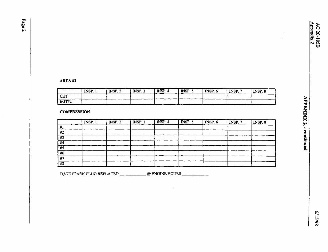
AREA #2
CHT EGT#2
JNSP. 1 lNSP. 2 INSP. 3 INSP. 4 INSP. 5 INSP. 6 INSP. 7 INSP. 8
COMPRESSION
\ I
#6 #7 #8
DATE SPARK PLUG REPLACED @ ENGINE HOURS

SPARK PLUG CONDITION: 1 = good 2 = worn 3 = oil fouled 4 = carbon fouled

FUEL BURN GPH
lNSP. 1 MSP. 2 INSP. 3 MSP. 4 INSP. 5 MSP. 6 INSP. 7 INSP. 8
AREA #3 ACCESSORIES
MAGNETO DROP @ 1500/1700 RPM
INSP. 1 INSP. 2 lNSP. 3 INSP. 4 l-tap. 5 MSP. 6 MSP. 7 INSP. 8 RT LT RT LT RT LT RT LT RT LT RT IT RT LT RT LT
VACUUM GAUGE @ 1500/1700 RPM ELECTRICAL VOLT/AMP @J 2100 RPM
n
MSP. 1 INSP. 2 INSP. 3 INSP. 4 INSP. 5 INSP. 6. INSP. 7 INSP. 8
h
AIR FILTER CONDITION
DATE AIR FILTER REPLACED
INSP.l 1 INSP.2 1 l-NSP.3 1 INSP.4 1 lNSP.5 ) INSP.6 1 INSP.7 1 lNSP.8
I I I I I I I