j. p. sheehan*, y. raitses**, n. hershkowitz*, i...
TRANSCRIPT
Plasma Science CenterPredictive Control of Plasma Kinetics
A comparison of inflection point and floating point emissive probe techniques for electric potential measurements in a
Hall thruster plasmaJ. P. Sheehan*, Y. Raitses**,
N. Hershkowitz*, I. Kaganovich**,and N. J. Fisch**
*University of Wisconsin – Madison
http://cae.wisc.edu/~sheehan
** Princeton Plasma Physics Laboratory

Plasma Science CenterPredictive Control of Plasma Kinetics
AbstractAccurate measurements of the plasma potential is a critical challenge especially for complex plasmas such as magnetized and flowing. We compare various emissive probe techniques for measurements of the plasma potential. The measurements were conducted in a low-pressure magnetized discharge of the Hall thruster. The thruster was operated with xenon gas in subkilowatt power range and the discharge voltage range of 200-450 V. The probe was placed at the channel exit where, the electron temperature is in the range of 10 to 60 eV and the plasma potential is in the range of 50 to 250 V. The floating point method is expected to give a value ~Te below the plasma potential. The experimental results are consistent with these expectations. Specifically, it is shown that the floating potential of the emissive probe is 1.5-2.5 Te below the plasma potential. It is observed that the separation technique varies wildly and does not give a good measure of the plasma potential.

Plasma Science CenterPredictive Control of Plasma Kinetics
Emissive probes can estimatethe plasma potential
• When heated, Langmuir probes thermionically emit electrons
• Generally, electrons can be emitted when the probe is biased below the plasma potential, but not when biased above the plasma potential
• Using emissive probes reduces the uncertainty of the measurement to the order of a wire temperature as opposed to an electron temperature with a collecting probe
• Emissive probes can measure the plasma potential in complex (e.g. flowing) plasmas
J. R. Smith, N. Hershkowitz, and P. Coakley. Inflection-point method of interpreting emissive probe characteristics. Review of Scientific Instruments, 50(2):210, 1979.

Plasma Science CenterPredictive Control of Plasma Kinetics
Motivation for evaluating emissive probe techniques
• There has been no rigorous comparison between any of the techniques
• All four methods analyzed here have been widely applied and are still currently used
• Disagreement between the techniques has been noted
J. R. Smith, N. Hershkowitz, and P. Coakley. Inflection-point method of interpreting emissive probe characteristics. Review of Scientific Instruments, 50(2):210, 1979.

Plasma Science CenterPredictive Control of Plasma Kinetics

Plasma Science CenterPredictive Control of Plasma Kinetics
Emissive probe construction
• 0.1mm diameter tungsten wire
• Boron nitride tube reduces secondary electrons emitted from probe shaft
• λde ~ rprobe, rL >> rprobe (rL is the Lamour radius), so on the edge of orbital motion limited regime
L. Dorf, Y. Raitses and N. J. Fisch, Review of Scientific Instruments 75 (5), 1255-1260 (2004).

Plasma Science CenterPredictive Control of Plasma Kinetics
Hall thruster setup with probe holder
L. Dorf, Y. Raitses and N. J. Fisch, Review of Scientific Instruments 75 (5), 1255-1260 (2004).

Plasma Science CenterPredictive Control of Plasma Kinetics
Parameters of Hall thruster plasma• Te ~ 10 to 60 eV
• ne ~ 109 to 1010 cm-3
• Neutral density ~ 1012 to 1013 cm-3
• Outer diameter: 123mm (~4.8 in)
• Inner diameter: 73mm (~2.9 in)
• Measurements taken 5mm from the thruster exit, 0 – 3mm radial inward from the outer wall
• Anode bias: 250 – 450 V
• Working gas: Xenon
• Mean free paths of electrons, ions, and neutrals are larger than the thruster size (~12cm diameter, ~2.5cm width)
• B field maximum ~ 100G
• B field at measurement locations ~50G

Φw ~TeΦ(x)
For Xe and γ =0 Φw ≈ 5.27Te
ew Tee e
mTn Φ−=Γπ2
MTn e
ion =Γ
eEM Γ=Γ γ
11e ionγ
Γ = Γ−
( )
−−≈Φ γ
π1
2ln
mMTew
ΓEM can be due to secondary electron emission or thermionic emissionIf γ →1: The walls act as an effective energy sink.
Effects of electron emission on plasma-wall sheath (Fluid theory): the plasma potential at the floating emissive wall is above the wall potential
Plasma Science CenterPredictive Control of Plasma Kinetics
Plasma Science CenterPredictive Control of Plasma Kinetics
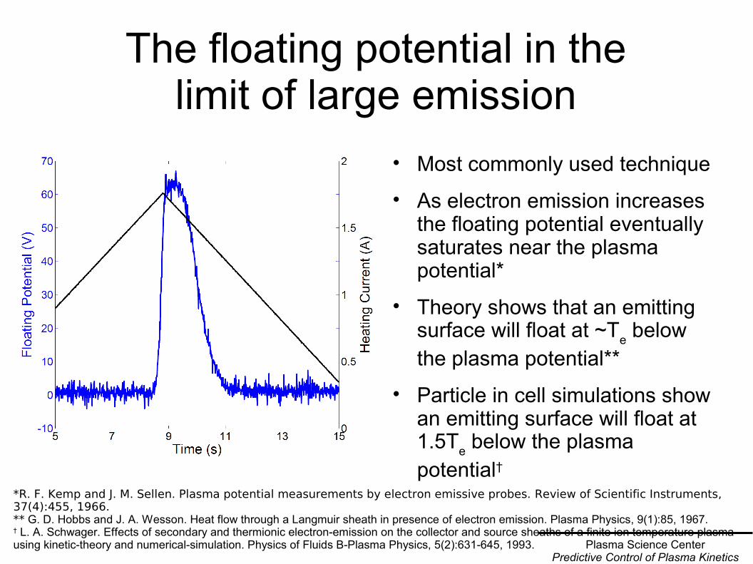
The floating potential in thelimit of large emission
• Most commonly used technique
• As electron emission increases the floating potential eventually saturates near the plasma potential*
• Theory shows that an emitting surface will float at ~Te below the plasma potential**
• Particle in cell simulations show an emitting surface will float at 1.5Te below the plasma potential†
*R. F. Kemp and J. M. Sellen. Plasma potential measurements by electron emissive probes. Review of Scientific Instruments, 37(4):455, 1966.** G. D. Hobbs and J. A. Wesson. Heat flow through a Langmuir sheath in presence of electron emission. Plasma Physics, 9(1):85, 1967.† L. A. Schwager. Effects of secondary and thermionic electron-emission on the collector and source sheaths of a finite ion temperature plasma using kinetic-theory and numerical-simulation. Physics of Fluids B-Plasma Physics, 5(2):631-645, 1993.

Plasma Science CenterPredictive Control of Plasma Kinetics
Inflection point in thelimit of zero emission
• Probe theory states that the inflection point of an emissive I-V curve approaches the plasma potential as emission goes to zero
• Reduces plasma perturbation as compared to the floating method
• Finding inflection points at a few (~5) emission levels and then extrapolating to zero emission gives the plasma potential
J. R. Smith, N. Hershkowitz, and P. Coakley. Inflection-point method of interpreting emissive probe characteristics. Review of Scientific Instruments, 50(2):210, 1979.
Plasma Science CenterPredictive Control of Plasma Kinetics
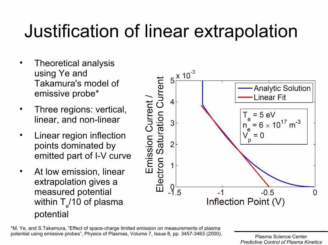
Justification of linear extrapolation • Theoretical analysis
using Ye and Takamura's model of emissive probe*
• Three regions: vertical, linear, and non-linear
• Linear region inflection points dominated by emitted part of I-V curve
• At low emission, linear extrapolation gives a measured potential within Te/10 of plasma potential
*M. Ye, and S.Takamura, ”Effect of space-charge limited emission on measurements of plasma potential using emissive probes”, Physics of Plasmas, Volume 7, Issue 8, pp. 3457-3463 (2000).

Plasma Science CenterPredictive Control of Plasma Kinetics
Inflection point of a warm, but not emissive probe
• Heating probe below emission level keeps it clean
• Probe theory indicates that there is an inflection point in the I-V curve at the plasma potential*
• Inflection point occurs at the transition from the exponential region to the linear region
• More uncertainty than the inflection point in the limit of zero emission method because only one measurement is taken.
*V. A. Godyak, R. B. Piejak, and B. M. Alexandrovich. Measurements of electron energy distribution in low-pressure rf discharges. Plasma Sources Science and Technology, 1(1):36, 1992.

Plasma Science CenterPredictive Control of Plasma Kinetics
Separation point method
• Plasma potential taken to be the point at which a cold I-V curve and an emissive I-V curve separate*
• Applied in the differential emissive probe technique
• No theoretical basis*Francis F. Chen. Electric probes. In Richard H. Huddlestone and Stanley L. Leonard, editors, Plasma Diagnostic Techniques, page 184. Academic Press, New York, 1965.

Plasma Science CenterPredictive Control of Plasma Kinetics
Comparing the different methods• Methods are compared
when thruster is at approximately the same discharge parameters and probe is in the same position
• Each measurement is normalized to the electron temperature taken at the same time
• Te is determined from the slope of the linear region of the semilog plot of a cold I-V trace (see figure)
Slope = 0.0568 V-1
Te = 17.6 eV

Plasma Science CenterPredictive Control of Plasma Kinetics
The floating method gives results lower than all other methods

Plasma Science CenterPredictive Control of Plasma Kinetics
Analysis of method comparison
• Inflection point in the limit of zero emission and the warm inflection point method yield approximately the same values
• Floating potential is expected to be Te – 1.5Te below the plasma potential*
• Since probe regime borders on orbital motion limit, this difference is expected to be reduced**
• Floating potential is ~2Te below the values of inflection point methods
*G. D. Hobbs and J. A. Wesson. Heat flow through a Langmuir sheath in presence of electron emission. Plasma Physics, 9(1):85, 1967. L. A. Schwager. Effects of secondary and thermionic electron-emission on the collector and source sheaths of a finite ion temperature plasma using kinetic-theory and numerical-simulation. Physics of Fluids B-Plasma Physics, 5(2):631-645, 1993.**L. Dorf, Y. Raitses and N. J. Fisch, Review of Scientific Instruments 75 (5), 1255-1260 (2004).

Plasma Science CenterPredictive Control of Plasma Kinetics
The separation method gives results inconsistent with all other methods

Plasma Science CenterPredictive Control of Plasma Kinetics
Uncertainty• Floating point method uncertainty from
identifying start of plateau region and is typically ~0.1Te
• Warm inflection point method uncertainty from identifying correct peak of dI/dV curve and is typically ~0.5Te
• Inflection point in the limit of zero emission uncertainty comes principally from uncertainty in linear fit and is typically ~0.1Te
• Separation point uncertainty due to large region over which separation occurs and is typically ~0.3Te
• There is an additional uncertainty of ~2V due to the voltage drop across the filament
Warm Inflection Point
Hot Inflection Point

Plasma Science CenterPredictive Control of Plasma Kinetics
Conclusions• Inflection point methods (emissive and cold probes) consistently agree with
each other
• The use of biased emissive probe with inflection point technique in the limit of zero emission allows to obtain less uncertainty than the inflection point of a biased cold probe
• The floating potential of an emissive probe is ~2Te below other measures of the plasma potential
• Separation point method does not accurately measure the plasma potential
• Current data suggests that the inflection point method in the limit of zero emission agrees with theoretical predictions and gives an accurate measure of the electric potential, though more work remains
• Simulations and detailed measurements of space charge effects are needed to definitively prove that the inflection point in the limit of zero emission is the plasma potential

Acknowledgments● This work was supported by US Department of Energy
grans No. DE-AC02-09CH11466, No. DE-FG02-97ER54437, No. 3001346357, and the Fusion Energy Science Fellowship
● Special thanks to Martin Griswold and Lee Ellison for all of their help
● For a copy of this poster, leave your email address or visit http://www.cae.wisc.edu/~sheehan