j. de haas. j. h. kamerlingh - dwc the two types as type i and type ii respectively. always as ......
TRANSCRIPT
Physics. - .. On the magnetic disturbance of the supraconductivity wlth mercury". I. By W. J. DE HAAS. G. J. SJzoa and H. KAMERLINGH
ONNES. (Comm. N°. 180d from the Physical Laboratory at Leiden).
(Communicated at the meeting of November 28. 1925).
§ 1. Purpose and method of the experiments. As was mentioned in § 5 of the preceding communication 1). the
purpose of the investigation which is to be recorded here. was to find out if the magnetic disturbance of the supraconductivity with mercury shows a similar hysteresis. as was observed with tin. In that case. there would be no doubt that this hysteresis had to be considered as a property of the supraconductivity and not as due to a contamination with iron.
The result of the investigation was not only that the hysteresis really exists. but besides that the graphs of the magnetic disturbance show verg sharp discon tin uities.
The measurements were carried out with mercury threads. enclosed in glasscapillaries which were provided with four platinum wires.
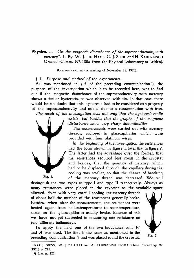
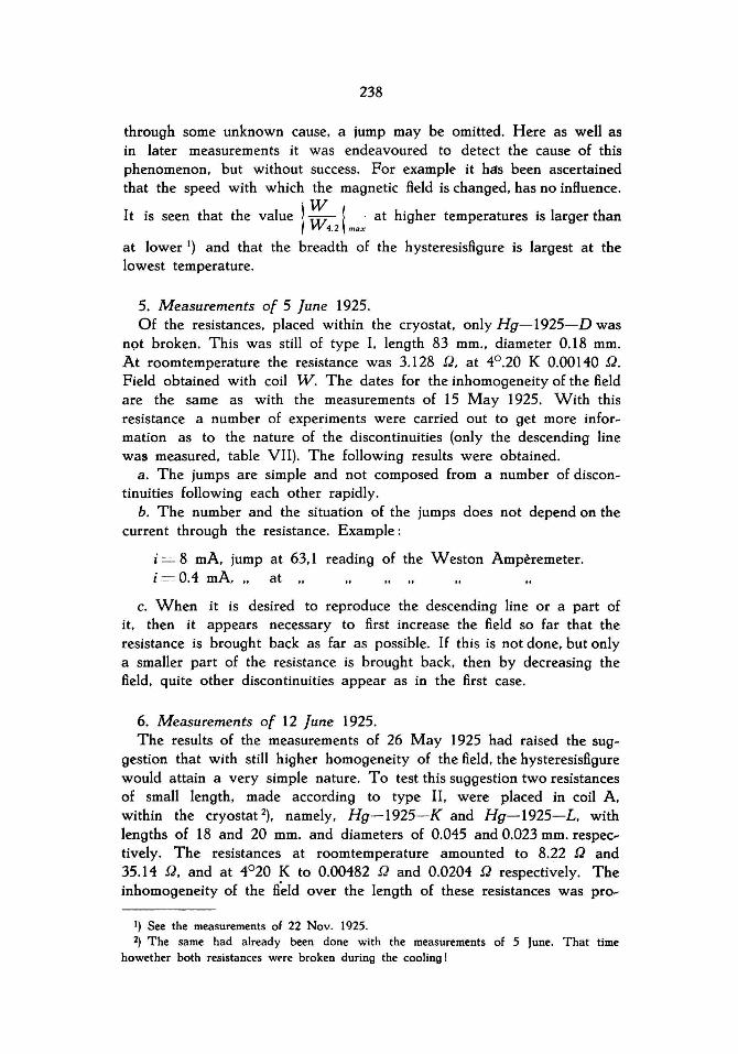
In the beginning of the investigation the resistances had the form shown in figure 1. later th at in figure 2. The latter had the advantage over the former. that the resistances required less room in the cryostat and besides. that the quantity of mercury. which had to be displaced through the capillary during the cooling was smaller. so that the chance of breaking
Fig. 1. of the mercury thread was decreased. We will distinguish the two types as type I and type II respectively. Always as many resistances were placed in the cryostat as the available space allowed. Even with very careful cooling the mercury threads of about half the number of the resistances generally broke. Besides. when af ter the measurements. the resistances were heated again from heliumtemperatures to roomtemperature. some on the glasscapillaries usually broke. Because of this we have not yet succeeded in measuring one resistance on two different heliumdays.
T 0 apply the field one of the two inductance coils W and A was used. The first is the same as mentioned in the preceding communication 2) and was placed round the cryostat. Fig. 2.
1) G. J. SIZOO. W. J. DE HAAS and A. KAMERLINGH ONNES. These Proceedings 29 (1926) p. 221.
2) L. c. p. 222.

234
The second was placed in the cryostat. lts length amounted to 16.5 cm .. internal diameter 2.10 cm.. number of turns 1500. In the beginning of the investigation the length of the resistances was rather great - e. g. 8 cm. Afterwards much smaller on es were used (10-15 mm.) For these latter the BeId obtained with coil A may be considered as practically homogeneous.
Only once we measured with a transverse BeId. obtained by means of an electromagnet with broad polepieces. between which the outer glass of the cryostat ju st fitted.
The resistances were measured again with the compensatiori apparatus. For the way in which the temperatures were determined we may refer to a preceding communication 1).
For the sake of sharp and quick observing of the discontinuous changes in the resistances the cOQperation of two ob servers appeared desirabie.
While by the first one the current through the coil was changed by means of variabie resistances as slowly and continuously as possible. the galvanometer was observed by the second. The appearance of a jump in the resistance was shown by a sudden deflection of the galvano~ meter. which by compensation had Brst been brought back to its nullpoint.
As soon as this happened the BeId was kept constant and the new value of the resistance measured.
By repetition the situation of a jump could be usually determined to some tenths of a gauss (0.1 to 0.2 scale division of the reading on the Weston~ampèremeter. with which the current was measured 2)).
§ 2. The measurements. As there were no data on the magnetic disturbance of the supracon~
ductivity with mercury. our Brst measurements had to be of an orienting nature.
We will record the course of the research in chronological order:
1. Measurements of 18 March 1925. Used resistance Hg-1925-A. Model 1. length of the capillary 11.5 cm ..
diameter 0.095 mmo Field obtained with coil W. Owing to lack of time the existance of the hysteresis could be only qualitatively ascertained.
2. Measurements of 30 April 1925. Used resistance Hg-1925-C, model I. length of the capillary 83 mm ..
1) These Proceedings 27 (1925) p. 656. 2) Of course the question arose during the investigation and especially in the beginning
as to whether the cause of the discontinuities did not lie in the apparatus. We therefore took all precautions to exclude this possibility (e.g. replacement of the SIEMENS and HALSKE
galvanometer by a ZERNIKE galvanometer with a sensibility three times as high. and a time of leg of only three seconds; the use of carbon rheostats. which might he varied in a very continuous way; the use of varipus calibrated milli-ampèremeters; of various leads etc.).

235
diameter 0.2 mmo Resistance at roomtemperature 2.648 Q. Field obtained with coil W. Data for the inhomogeneity of the field. I)
Amax = 0.783;
Aa.f/ = 0.765 ;
A min = 0.699 ; AAmtn = 0.893; max
Ha.fj (in gauss) = 35.09 i (i in ampères).
The results of the measurement, carried out 4°.036 K are contained in table I. The number of points is too small to show the form of the hysteresisfigure with certainty. The "descending line" shows a horizontal part, which raised the suspicion of discontinuity.
3. Measurements of 15 Mag 1925. Resistance Hg-I925-E, model I, leng th 83 mm., diameter 0.2 mmo
The hysteresisfigure was determined at a temperature of 3°.796 K., with a longitudinal field (coil W) as weil as with a transverse field (electro~
magnet) . In both cases in the descending curves discontinuities were observed. (See tables II and IlI).
For the longitudinal field we had:
Amax = 0.783;
A •• g = 0.765;
Am'n = 0.699;
Ha.g = 35.09 i.
Amax = 0.893; Am;n
The inhomogeneity of the transversal field was not determined. The mean point for us was to know whether or not there existed ah essential difference between the behaviour of the resistance in a longitudinal and a transverse field . This appeared not to be the case. Although not all jumbs in the descending curves were determined with certainty, still it is sure, that neither their number nor their situation were the same in both cases. The ascending lines are not observed with sufficient accuracy to decide the pres en ce or absence of discontinuities. A remarkable result of this measurement was further that the maximum value of the resistance, which could be brought back by the magnetic field, amounts only to 70 010 of the resistance at 4°.20 K., just above the "vanishing~point". In the tables are given, besides the values of the resistances, the ratios of these values to the value of the resistance at 4°.20 K. These quotients are called
W W . The maximum value of this quotient amounts to 0.70 for the
1.2
longitudinal and 0.706 for the transverse field. This partial return of the resistance, confirmed by all further measurements, was later especially investigated. 2)
4. Measurements of 26 Mag 1925. Used resistance Hg~1925~G, model Llength 24 mm., diameter 0.052 mmo
Resistance at roomtemperature 8.20 Q; at 4°20 K. 0.00378 Q.
The length of the resistance was made short to get a higher homo~
I) See preceding communication. These Proceedings 29 (1926) p. 222 . 2) See measurements of 22 Nov. 1925, mentioned in second part of th is communication.
16 Proceedings Royal Acad. Amsterdam. Vol. XXIX.

236
geneity of the field over the length of the resistance. With th is measure~ ment the jumps were observed for the first time on the method. mentioned in § 1. The field was obtained with coil W.
In the ascending as weU as in the descending line discontinuities were observed.
The tables IV and V contain the results of the measurements. carried out at temperatures of 3°.796 and 3°.962 K. with currents of 4 and 2 mA. respectively. For these measurements the resistance was placed. as usual in the middle of the coil. The values of A were
Amax = 0.783; A m /n = 0.778; AAmin = 0.994; max
A ovil = 0.781 ;
1.00
0.80
0.60
0 .40
0.20
w W ('2 0 :00
62 -H
H ovil = 35.82 i.
I
I
; r
67 72 77G
Fig. 3.
To detect the influence of the inhomogeneity of the field. the coil was displaced ab out 6 cm. in reference to the resistance. so that this now situated in a much less homogeneous field. The data of the inhomogeneity now were:
A mox = 0.705;
AI/om = 0.657 ;
A min = 0.596 ;
H llom = 30.13 i. AAmin = 0.845;
max

237
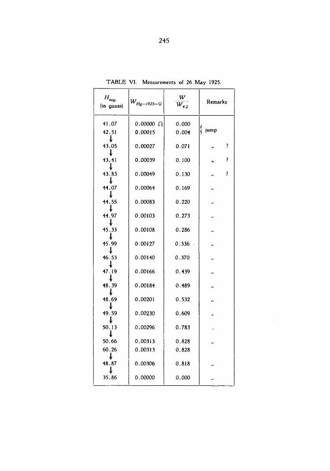
The results. stated in table VI were th us obtained. The temperature again amounted to 3°.962 K. the measuring current was 2 mA.
The data from table IV are represented in fig . 3. those from tab Ie V and VI in fig. 4.
From fig. 4 it is c1ear that the influence of the inhomogeneity of the field is feIt principally in the increase of the number of jumps in the ascending line 1). The descending line retains its simple nature. which
1.00,.--------,-----,.-------,------,
0.601----H- f--- ----,!j-·--- - - _+_
j 1 0.401-----+··· -- - - .- .. _- - -If----._---fl-t-------j
inhomogeneous field
seems to indicate that the resistance o{ a part ot the thread can only disappear when over its whole length the field strength has (allen be/ow a certain value. The dotted parts in both figures show that sometimes.
1) As the resistances are plotted against the average va lues of the field a displacement of the ascending line to the side of the lower fields would he expected rat her than the displacement to the higher fields. which is seen from the figure . The latter may be due to an error in the measurement of the dis placement of the coi! (perhaps th is amounted to 7 cm. instead of 6 cm.). Because of this uncertainty we did not try to compare the both figures from a quantitative point of view. (Note added in the translation).
16*
238
through some unknown cause, a jump may be omitted. Here as weIl as in later measurements it was endeavoured to detect the cause of th is phenomenon, but without success. For example it has been ascertained th at the speed with which the magnetic field is changed, has no influence.
' W It is seen th at the value 'W ! . at higher temperatures is larger than
, 4.2 \ max
at lower 1) and that the breadth of the hysteresisfigure is largest at the lowest temperature.
5. Measurements of 5 June 1925. Of the resistances, placed within the cryostat, only Hg-1925-D was
n<;>t broken. This was still of type I. length 83 mm., diameter 0.18 mmo At roomtemperature the resistance was 3.128 Q. at 4°.20 K 0.00140 Q. Field obtained with coil W . The dates for the inhomogeneity of the field are the same as with the measurements of 15 May 1925. With this resistance a number of experiments were carried out to get more infor~ mation as to the nature of the discontinuities (only the descending line was measured, table VII). The following results were obtained.
a. The jumps are simple and not composed from a number of discon~ tinuities following each other rapidly.
b. The number and the situation of the jumps does not depend on the current through the resistance. Example :
i = 8 mA, jump at 63,1 reading of the Weston Ampèremeter. i=0.4 mA." at
c. When it is desired to reproduce the descending line or a part of it, th en it appears necessary to first increase the field so far that the resistance is brought back as far as possible. If this is not done, but only a smaller part of the resistance is brought back, th en by decreasing the field, quite other discontinuities appear as in the first case.
6. Measurements of 12 June 1925. The results of the measurements of 26 May 1925 had raised the sug~
gestion that with still higher homogeneity of the field, the hysteresisfigure would attain a very simple nature. To test this suggestion two resistances of small length, made according to type 11, were placed in coil A. within the cryostat 2), namely, Hg-1925-K and Hg-I925-L. with lengths of 18 and 20 mmo and diameters of 0.045 and 0.023 mmo respec~ tively. The resistances at roomtemperature amounted to 8.22 Q and 35.14 Q, and at 4°20 K to 0.00482 Q and 0.0204 Q respectively. The inhomogeneity of the fi'eld over the length of these resistances was pro~
1) See the measurements of 22 Nov. 1925. 2) The same had already been done with the measurements of 5 June. That time
howether both resistances Wf're breken during the cooling!

239
bably too small to have any influence : Amax = A tnin = A.ug = 0.992. H = 113.3i. At 3°.790-3°.793 K. for both resist~nces the hysteresisfigures we re determined: table VIII (Hg-1925-L); table IX (Hg-1925-K) and figure 5. The figure shows. how. notwithstanding the homogeneity of the field. the hysteresisfigures are not so simple as was expected.
The ascending lines in both cases are continuous again . As the gal~ vanometer was observed continuously during the gradually increasing of the field. the absence of discontinuities is more certain than is indicated
1.00
0 _80 1--------- - -- - - - - r-~-=--
-~ '"
1 ( ( - -
I
J t r"-
I/
0.60
0 .40
I
) l/ 0.20
6-1 66 tI 18 8\0
Fig 5.
o I V \ Hg-1925-L 81 X \ Hg-1925-K
by the few number of measured points. The descending curves show -4 and 3 jumps respectively and the breadth of the figure is particularly great. The unexpectedness of these results gave us cause to suppose. that perhaps local inhomogeneities in the magnetic field would cause the discontinuities. To test this possibility it was resolved to measure a hysteresisfigure with coil A as well as with coil W . This was carried out during the:
240
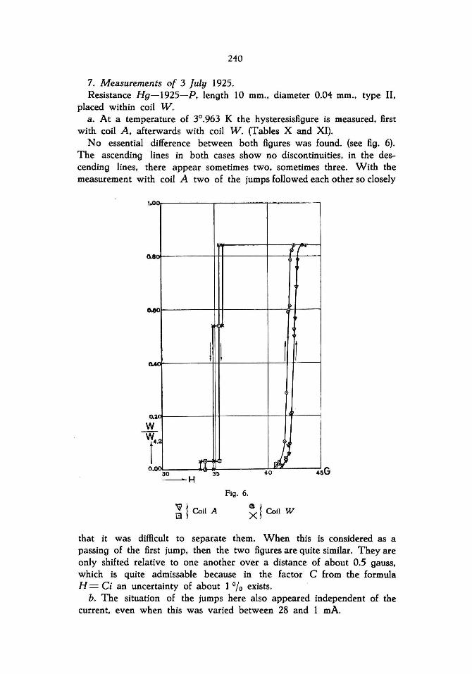
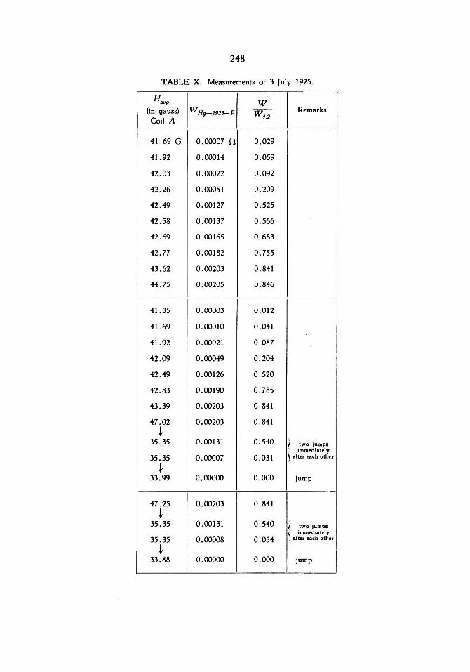
7. Measurements of 3 July 1925. Resistance Hg-1925-P, length 10 mm., diameter 0.04 mm., type I1,
placed within coil W. a. At a temperature of 3°.963 K the hysteresisfigure is measured, first
with coil A, afterwards with coil W. (Tables X and XI). No essential difference between both figures was found. (see fig. 6).
The ascending lines in both cases show no discontinuities, in the descending lines. there appear sometimes two, sometimes three. With the measurement with coil A two of the jumps followed each other so c10sely
1.0
8
....
a.~
w W
r2
0.'"
;
l I f 1
.,~
rr-:' JJ 30 ~H
40
Fig. 6.
~ \ Coil A ~d Coi! W
that it was difficult to separate them. When this is considered as a passing of the first jump, then the two figures are quite similar. Theyare only shifted relative to one another over a distance of about 0.5 gauss, which is quite admissable because in the factor C from the formula H = Ci an uncertainty of about 1 % exists.
b. The situation of the jumps here also appeared independent of the current, even when this was varied between 28 and 1 mA.

TABLE I. Measurements of 30 April 1925.
I H I) H BU9·
W Hg-1925-C 8"9 -
W Hg- 1925- C (in gauss) (in gauss)
21 .05 0 .00000 n 22.67 0.00072 n 21 .56 0.000"10 21.79 0 .00012
28 .07 0 .00107 21 . 05 0.00013
31 .58 0.00111 20 . 35 0.00011
35 . 09 0.00113 19 .65 0 .00009
38. 60 0.00111 18 .95 0 .00000
35 .09 0 .00112 19 . 65 0 .00000
31. 58 0 .00112 20 .12 0.00000
21.56 0 .00112 21 .05 0.00002
TABLE 11. Measurements of 15 May 1925.
Hovg . W
(in gauss) WHg-1925-E --- Remarks
transversal W 1.2
56.78 0 .00000 n 0.00
61.8"1 0 .00011 0.10
69 .00 0.00025 0.2"1
73 . 15 0.00058 0 . 55
77 . 22 0.00068 0 .65
81.87 0 .00075 0.71
89 . 93 0.00079 0 . 75
85 . 29 0.00075 0.71
77.11 0 .00076 0 . 72
69 .00 0.00071 0 . 70
65 . 71 0.00071 0.70 I jump
65.33 0 .00061 0.58 \
61.60 0.00061 0 . 58
62.72 0 . 00055 0.52
61. 91 0 .00055 0.52
60. 85 0.00055 0.52
59 .63 0 .00055 0 .52 I ) ..
58 . "11 0 .0003"1 0 . 32 ! ? ..
56.78 0.00025 0.2"1 i ..
51 . 99 0 . 00013 0.12 \
53.76 o 00013 0 . 12
52 . 13 0 . 00013 0.12
"18.63 0 .00013 0 . 12 I .. ?
0 .00000 0 .00 Î
I) When there is nothing mentioned to the contrary the magnetic field was longitudlnal. i. e., parallel to the lenght of the mercury thread.
242
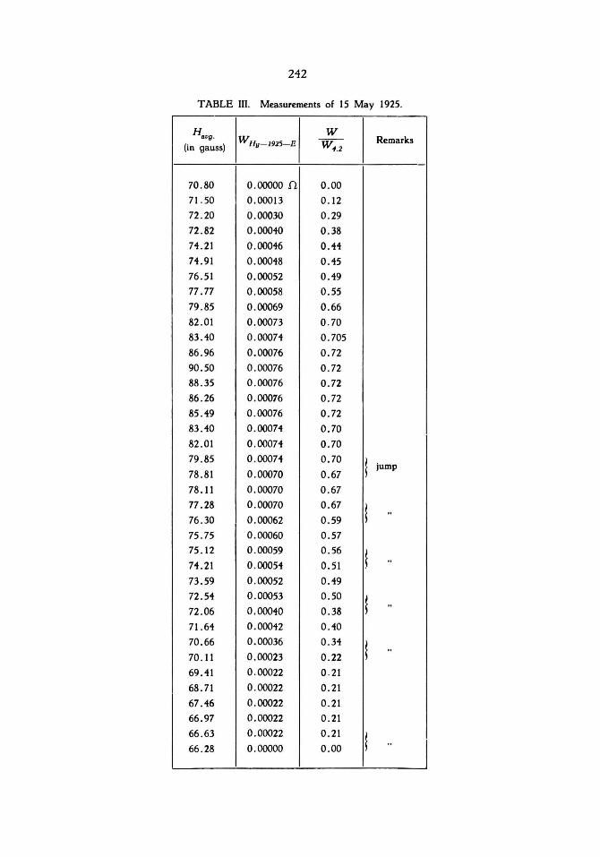
T ABLE lIl. Measurements of 15 May 1925.
H W avg. WHg- J9Z5-E W 4.Z
Remarks (in gauss)
70.80 0.00000 n 0.00 71 .50 0.00013 0 . 12 72 .20 0.00030 0.29 72 .82 0.00040 0 .38 74 .21 0 .00046 0.44 74 .91 0.00048 0.45 76.51 0.00052 0.49 77.77 0.00058 0 .55 79.85 0.00069 0.66 82 .01 0.00073 0.70 83 .40 0.00074 0 .705 86.96 0.00076 0.72 90.50 0 .00076 0 .72 88 .35 0 .00076 0.72 86 .26 0.00076 0.72 85 .49 0.00076 0.72 83 .40 0.00074 0.70 82 .01 0.00074 0.70 79 .85 0.00074 0. 70
t 78 .81 0.00070 0.67 jump
78.11 0.00070 0.67 77 .28 0 .00070 0.67
t .. 76.30 0 .00062 0 .59 75 .75 0.00060 0.57 75 . 12 0.00059 0 .56
t 74.21 0.00054 0. 51 ..
73.59 0.00052 0.49 72.54 0 .00053 0 .50
t 72 .06 0.00040 0 .38 ..
71.64 0.00042 0.40 70.66 0.00036 0.34
t .. 70 . 11 0.00023 0.22 69.41 0.00022 0 .21 68.71 0.00022 0.21 67 .46 0.00022 0.21 66.97 0.00022 0.21 66.63 0 .00022 0.21
t 66 .28 0 .00000 0 .00 ..

243
T ABLE IV. Measurements of 26 May 1925. I)
I H a,'g. W
WHg - J925 - G - - Remarks
(in gauss) W 4.2
71 . 56 0.00000 11 0.000
\ 71.70 0.00016 0.042 jump
t 72.16 0 .00035 0.093 ..
t 72.34 0 .00042 0.112 ..
t 72.77 0.00046 0.121 ..
t 72 .91 0 .00049 0.131 ..
t 73.34 0 . J0053 0 . 141 ..
t 73.91 0.00068 0.179 ..
t 74.19 0.00072 0 . 192 ..
t 74.26 0.00089 0 . 236 .. ?
t 74.41 0.00175 0.463 .. ?
t 74.6 0 .00282 0.746 .. 94.6 0 .00282 0.746
t 69.8 0 .00271 0.718 ..
t 66.57 0 . 00000 0.000 .,
1) The arrows in this and the following tables indicate that during the changing of the magnetic neld the resistance remained nrst constant and then suddenly changed to a new value. Thus they correspond with the horizontal parts of the disturbance-lines.
Very of ten between two jumps it was controlled by special measurement that the reslstance did not alter. These measurements have been omitted in the tab les and ngures. Where there was no certainty as to the presence of ajump. this has been queried in the tables.

244
TABLE V. Measurements of 26 May 1925.
H W avg.
W Hg-1925-G W~.2 Remarks
(in gauss)
37 . 77 0 .00000 n 0.000 ! 38 .06 0.00017 0.045 jump
i 39.34 0.00025 0 .065 ..
i 39.84 0.00039 0.104 ..
i 40 .20 0 .00047 0 . 123 ..
i 40.48 0 .00054 0 . 142 ..
i 41.20 0 .00059 0.155 ..
i 41 .48 0.00069 0.181 ..
i 41.62 0.00076 0.201 ..
i 41 .98 0 .00225 0 .596 .. ?
i 42.12 0.00288 0.762 ..
i 42.55 0.00313 0.828 .. 53 .81 0.00313 0.828
i 35.06 0.00032 0 .085 ..
i 34.42 0.00000 0.000 ..
53.81 0.00313 0.828
i 36.78 0.00306 0.810 jump
i 35.14 0 .00032 0 .085 ..
i 34.40 0.00000
I 0.000 ..
53.81 0.00313 0.828 i
36.85 0.00306 0.810 jump
i I 35.06 0.00000 0.000 ..
245
T ABLE VI. Measurements of 26 May 1925.
H W aug . WHg-1925-G W~.2
Remarks (in gauss)
41 .07 0.00000 n 0 .000 l jump 42.51 0 .00015 0.004 ~
43 .05 0.00027 0.071 .. ?
~ 43.41 0.00039 0.100 "
?
~ 43.83 0.00049 0.130 .. ?
~ 41.07 0.00064 0.1 69 ..
~ 41.55 0.00083 0.220 ..
~ 44 .97 0 .00103 0 .273 ..
~ 45.33 0.00108 0.286 ..
~ 45.99 0.00127 0 .336 ..
t 46 .53 0.00140 0.370 ..
~ 47.19 0.00166 0.439 ..
~ 48.39 0.00184 0.489 ..
t 48 .69 0 .00201 0 .532 ..
~ 49 .59 0.00230 0.609 ..
~ 50 . 13 0.00296 0 . 783 ..
~ 50 .66 0.00313 0.828 .. 60 .26 0.00313 0.828
t 48.87 0.00306 0 .818 ..
~ 35 .86 0.00000 0.000 ..

246
TABLE VII. Measurements of 5 June 1925.
Ha.g. W WHg-1925-D Wo
Remarks (in gauss)
96 .36 0.00107 11 0.764
~ 55.41 0.00102
~ 0.728 jump
53.69 0 .00100 0.714 "
~ 50.18 0.00081 0.578 "
~ 49.34 0.00076 0 .540 "
~ 41.56 0.00037 0 .261 "
~ 42.74 0.00031 0.218 "
~ 41.62 0 .00010 0.070 ..
~ 36.84 0.00000 0.000 "
TABEL VIII. Measurements of 12 June 1925.
Ha.g. W WHg-1925-L W 4.2
Remarks (in gauss)
69.91 G 0.0000011 0.000
72 .10 0 .00071 0.035
75.23 0.00364 0. 179
76.25 0.00684 0.336
77 .27 0 .01169 0.574
78.06 0 .01455 0.715
79 .31 0 .01519 0 .746 jump7
87 . 13 0.01526 0.750
113.3 0.01519 0 .746
~ 67 .87 0 .01341 0.660 jump
~ 64.35 0.00995 0.489 "
~ 57.22 0.00000 0.000 "

247
TABLE IX. Measurements of 12 June 1925.
H / W Hg- 1925-K/
W
/
8."9· - --- Remarks (in gauss) W~.2
69 .68 0.00000 [l 0.000
70 .24 0.00012 0.025
70 .81 0.00076 0.158
71.38 0.00185 0 .384
72.29 0.00325 0.674
73 .42 0.00343 0.712
73.65 0.00353 0.732
73.98 0 .00360 0. 747
74.44 0.00348 0.722
75 .00 0.00370 0.768
7568 0 .00372 0.772
77.61 0.00372 0.772
84.40 0.00377 0.782
91.43 0.00375 0.778 t
64.81 0.00330 0.685 jump t
61.86 0 .00232 0 .481 .. t
60 .84 0.00148 0.307 .. t
I 57.56 0.00000 0.000 ..
69 . 23 0.00000 0 .000
70 .36 0.00017 0.035
71.04 0.00042 0.087
71.27 0 .00067 0.139
71.61 0.00141 0.293
71.95 0.00192 0.398
72.29 0.00232 0.481
72.85 0 .00321 0.666 jump?
73 .42 0.00335 0 .695 .. ?
73.65 0.00335 0.695
73.98 0.00350 0.726
74.78 0.00362 0.751
248
TABLE X. Measurements of 3 July 1925.
H W I 81)9·
(in gauss) WHg-192S-P W.,.2 Remarks
Coil A
41.69 G 0.00007 n 0.029
41.92 0.00014 0 .059
42.03 0.00022 0 .092
42.26 0.00051 0.209
42 .49 0.00127 0.525
42 .58 0.00137 0.566
42.69 0.00165 0.683
42.77 0 .00182 0.755
43.62 0 .00203 0.841
44 .75 0.00205 0.846
41.35 0.00003 0 .012
41.69 0.00010 0.041
41.92 0.00021 0.087
42.09 0 .00049 0.204 I
42.49 0.00126 0.520
42.83 0.00190 0.785
43.39 0.00203 0.841
47.02 0.00203 0.841 ~
35.35 0.00131 0.540 ) two jumps > immediately
35.35 0 .00007 0.031 ~ aher each other
~ 33 .99 0.00000 0.000 jump
47.25 0.00203 0 .841 ~
35 .35 0 .00131 0 .540 ~ two jumps \ immediately
35 .35 0.00008 0.034 .hu each other
~
I 33.88 0.00000 0.000 jump

249
TABLE XI. Measurements of 3 July 1925.
H W aug.
(in gauss) WHII-1925- P - - Remarks
Coi! W W 1.2
40 .70 0 .00003 I 0.012
41 .04 0.00006 0.024
41 . 56 0.00025 0.102
41.92 0 .00113 0.590
42 .06 0 .00148 0.612
42.12 0 .00190 0.785
42 .26 0.00198 0.821
43 .26 0 .00203 0.841
~ 56 . 70 0.00203 0 .841
~ 35 . 70 0.00131 0.540 jump ~
34 .80 0 .00000 0.000 ..
40.70 0.00005 002
41.06 0 .00005 0.02
41 . 76 0.00069 0 .285
41 .98 0 .00144 0.597 "
42.48 0 .00203 0.841
56.70 0 .00203 0. 841
~ 35 .80 0 .00131 0.540 jump
~ 34.78 0.00010 0 .041 n
~ 33.56 0 .00000 0 .000 ..