j b.tech. (sem. - gndec.ac.inlibrarian/question papers/q-papers 2009/b.tec... · ......
TRANSCRIPT

RQII No. ......................
Total No. of Questions : 09]
'.j., [Total No. of Pages: 04
B.Tech. (Sem. -3rd)
MACHINE DRAWINGSUBJECT CODE: PE -203
. .
Paper ID : [A0203]
[Note: Please fill subject code and paper ID on OMR]
Time: 03 Hours
Instruction to Candidates:
1) Section -A is Compulsory.
2) Attemptany Fou.rquestionsfrom Section- B.3) Attempt any Two questions'from SectioR- C. ~
Q1)
Maximum Marks: 60
Section -A
(10 X 2 =20)
a)
b)
c) ,
d)
e)
t)
g)
h)
i)
j)
What is engineering drawing?
Name the different types of sections.
Why dimensioning is necessary?
Draw a symbol of single V-butt welding.
Draw the symbol of third angle projection~.
Name the different types of couplings,
What is the function' of cross-head?
What is an isometric projection?
What is the size of A4 sheet?
Sketch the convention of a centre line.
Section -B
. (4 x 5 =20)
Q2) (a) .. State the parts ~hich are not to be shown in sectiqn, althoughthe sectionplane 'may cut them.
(b) Show the convention representation 'of plywood, w~x and kerosene.
Q3) What are multi start threads? Where these ar~'used' and why?. .
Q4) What is the difference between ~sometric and.orthographic projections? - .
M-J88/1859} P.T.o. .

(25) Make the freehand sketches of the (a) single rivetedjoint (b) welded joint.
Q6} Twoviews of an I.C. engine piston are given in Figure 1. Draw its front vi~~full in section. ~
Lat"""),.
,"f'ii
2.5
-,-0 Q)
~.:10 .. L .
Figure 1
M-188 2
Section - C
. (2 XJ 0 =20)
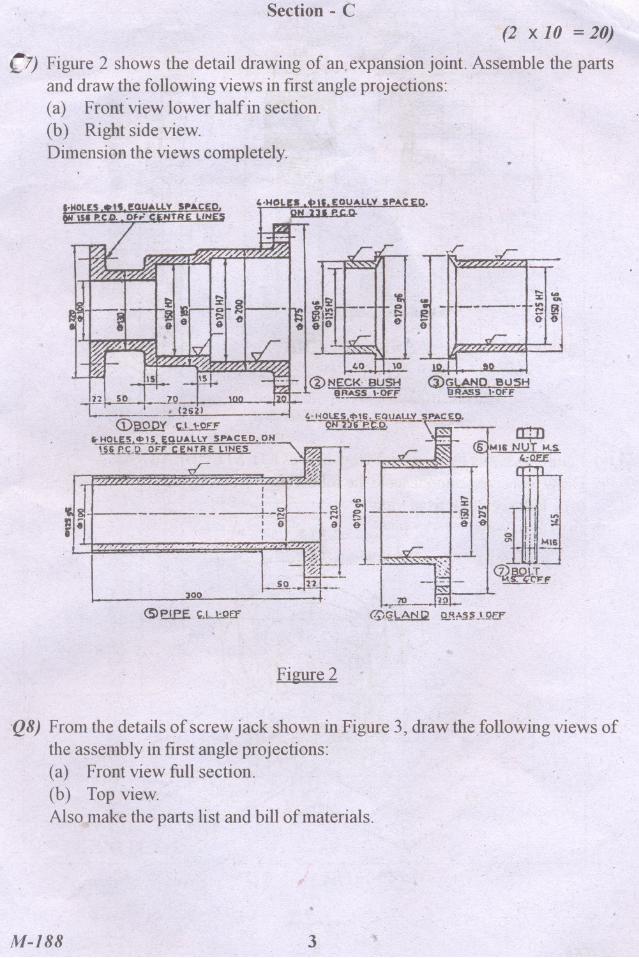
L7) Figure 2 shows the detail drawing of an, expansion joint. Assemble the partsand draw the followingviews in first angle projections: '
(a) Front'view lower half in section.(b) Right side view.Dimensionthe views completely.
..r
"'"
,
...:z; ...
-"' gri
Jt.j
'~
!1~!!--c.:= ,..!..l1ill<DI2QID' 'c.!..1:2ff
~HOlE5.~I~EQUAlLY SPACED.~~Uif'.t;J2 OFF CENTRE lINES
rr.'~ ,'".,-err7/7?,"," ,.,
V
SPA'<.Eo. rrt'T\6 EQ\JAI~, ~"~4>;-P.~b-:- ~~ r
NUT M.S-. - ((j~" IdlU
,
=1-re
/I.IL_~I -I eII ,
"Tn7"C-CT'.'7:='~~0:-'-"" '0''',' """,,? /n~ ~;-o-;~. .
!Q.-~~ffi=,-300 ' .1.
---'--
<S> eJ.eE ~L!:QEf
Figure 2
'Q8) From the details ofscrewj'ack shown in Figure 3, draw the Jollowing views ofthe assembly in first angle projections:(a) Frontview full section.(b) Top view.Also make the parts list and bill of materials. '
.M-188 3

..i..:,.1
'I
Figure 3
~-'
-0 <i).
~.' ~',
/ 51I
.
.
. .Q9) Figure 4 shows the pictorial view of a'FOOT STEP BEARING
Draw to a conventional scale the following:(a) Full sectional ITontview(b) Top View.
Figllre4PI~cf>31 lONG 10
M-J88DDD
4