j a'* sfi 5> operators manual and snow blowers blower... · the principle components and...
TRANSCRIPT
;-i .:: j
i t;. -.,'.:
FHIj A'* sfi * 5">Operators ManualH80 and H84Snow Blowers
Win. Form No. 9-35302
INTRODUCTION
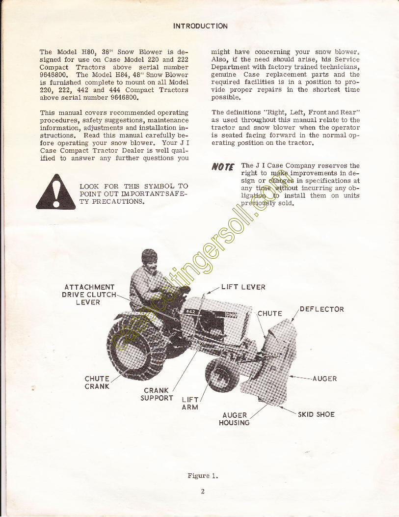
The Model H80, 38t' Snow Blower is de-signed for use on Case Model 220 and 222Compact Tractors above serial number9646800. The Model H84, 48" Snow Bloweris furnished complete to mount on aII Model220, 222, 442 and 444 Compact Tractorsabove serial number 9646800.
This manual covers recommended operatingprocedures, safety suggestions, maintenanceinformation, adjustments and installation in-structions. Read this manual carefully be-fore operating your snow blower. Your J ICase Compact Tractor Dealer is well qual-ified to answer any further questions you
LOOK FOR THIS SYMBOL TOPOINT OUT IMPORTANT SAFE.TY PRECAUTIONS"
ATTACHMENTDRIVE CLUTCH
LEVER
CHUTECRANK
CRANKSUPPORT
might have concerning your snow blower"AIso, if the need should arise, his ServiceDepartment with factory trained technicians,genuine Case replacement parts and therequired facilities is in a position to pro-vide proper repairs in the shortest timepossible.
The definitions "Right, Left, Front and Rear"as used throughout this manual relate to thetractor and snow blower when the operatoris seated facing forward in the normal op-erating position on the tractor.
tQfE The J I Case Company reserves theright to make improvements in de-sign or changes in specifications atany time without incurring any ob-Iigation to install them on unitspreviously sold.
DEFLECTOR
*-__- AUGER
AUGERHOUSING
SKID SHOE
LIFTARM
Figure 1.
2
The principle components and controls ofthe tractor and snow blower are identifiedin Figure 1 with the same description usedthroughout this manual. Refer to the trac-tor Operator's Manual for identification ofall tractor controls.
The chute crank, attachment drive clutchand lift lever controls are aII convenienilv
OPERATING CONTROLS
OPERAT ING SAF ETY SUGGESTIONS
located near the operator's position on thetractor. The auger is placecl in motion bypulling outward on the tractor attachmentdrive clutch lever. The chute crank adjuststhe direction of snow discharge and thedeflector angle controls the distance thesnow is blown.
Read Safety Precautions Care-fully.
o
10.
11.
12.
13.
t4.
15.
1.
2.
e
5.
6.
7.
B.
Regard your snow blower as a piece ofpower equipment and be sure this isunderstood by all who operate it.
Never allow children or young teen-agers to operate the tractor and snowblower.
Be sure you know how to stop the trac-tor and auger at a moment's notice.
Instruct children to keep away from thearea of operation at all times.
Check the tractor and blower to makecertain both are in good operating con-dition"
FiIl gas tank out of doors and avoidspilling gasoline. Do not fill tank withgasoline while smoking or while engineis running.
Give complete and undivided attentionto the job at hand.
#
Keep the area clear of all persons,particularly small children.
Stop engine and disengage attachmentdrive clutch when tractor is unattended.
Disengage attachment drive clutch whensomeone approaches.
Do not allow anyone other than the op-erator to ride on the tractor or to betowed behind.
Extreme caution should be exercisedun-der slippery conditions. Reduce for-ward speed. Install tire chains andwheel weights to traction wheels foradded safety.
DO NOT ATTEMPT TO CLEAR AUGEROR DISCHARGE CHUTE WHILE ENGINEIS RUNNING.
When changing position of the deflector,disengage the attachment drive clutchand stop engine.
Never direct snow discharge at peopleor buildings.
Disengage attachment drive clutch whentransporting.
16.
OPERATING TIPS
A
5.
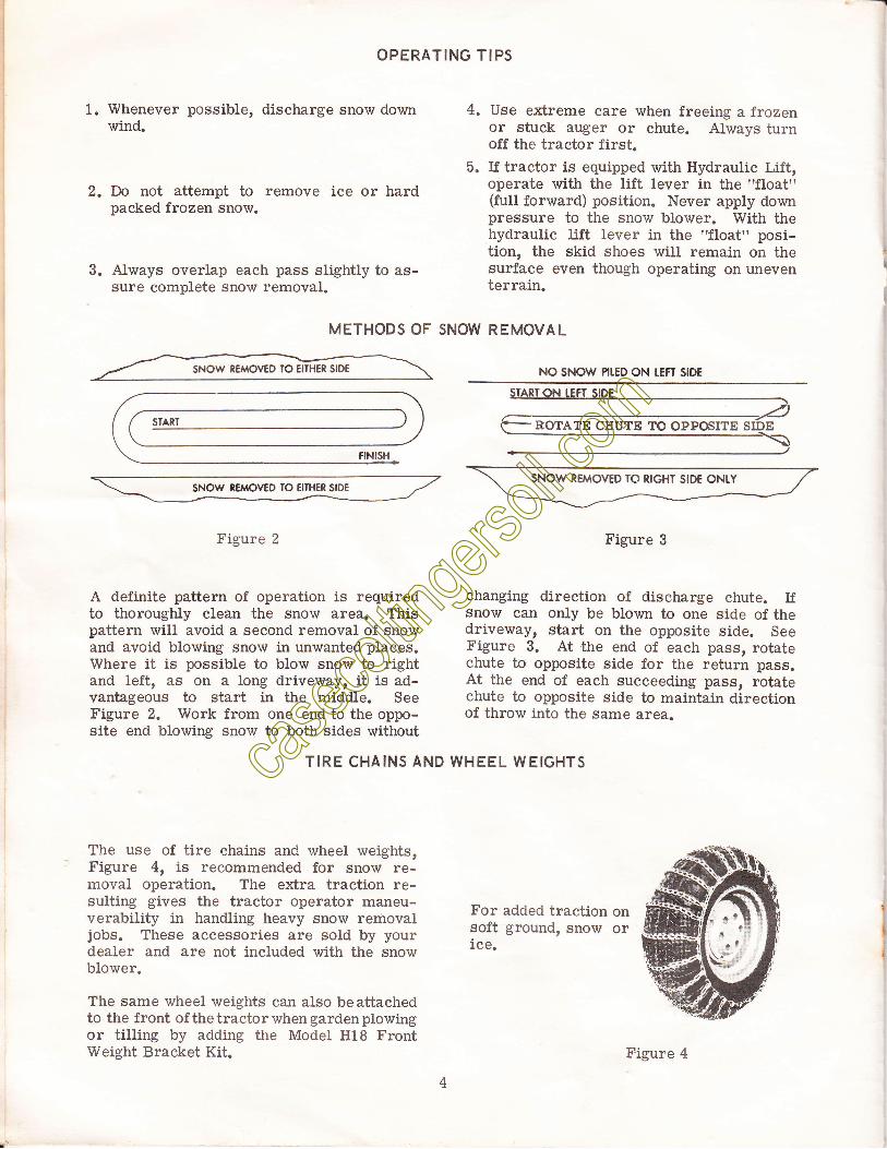
1. Whenever possible, discharge snow downwind.
Do not attempt to remove ice or hardpacked frozen snow.
Always overlap each pass slightly to as-sure complete snow removal.
Use extreme care when freeing a frozenor stuck auger or chute. Always turnoff the tractor first.If tractor is equipped with Hydraulls T,iff,operate with the lift lever in the "float"(full forward) position. Never apply downpressure to the snow blower. With thehydraulic lift lever in the ?'floatrr posi-tion, the skid shoes will remain on thesurface even though operating on uneventerrain.
,.
3.
METHODS OF SNOW REMOVAL
Fisure 2
A definite pattern of operation is requiredto thoroughly clean the snow area. Thispattern wiII avoid a second removal of snowand avoid blowing snow in unwanted places.Where it is possible to blow snow to rightand left, as on a long driveway, it is ad-vantageous to start in the middle. SeeFigure 2. Work from one end to the oppo-site end blowing snow to both sides without
NO SNOW PILED ON IEFT SIDE
Figure 3
changing direction of discharge chute. Ifsnow can only be blown to one side of thedriveway, start on the opposite side. SeeFigure 3. At the end of each pass, rotatechute to opposite side for the return pass.At the end of each succeeding pass, rotatechute to opposite side to maintain directionof throw into the same area.
TIRE CHAINS AND WHEEL WEIGHTS
The use of tire chains anC r,vheel weights,Figure 4, is recommended for snow re-moval operation. The extra traction re-sulting gives the tractor operator maneu-verability in handling heavy snow removaljobs. These accessories are sold by yourdealer and are not included with the snowblower.
The same wheel weights can also be attachedto the front of thetractorwhengardenplowingor tilling by adding the Model H18 FrontWeight Bracket Kit.
For added traction onsoft ground, snow orice. I
I
ROTATE CEUTE TO OPPSITE
Figure 4
II
PREPARING FOR SNOW REMOVAL
Disengage the attachment driveclutch when starting engine andwhen transporting the snowblower. Before the first snow-fall, the area in which snow re-moval is to take place shouldbe cleared of all stones, sticks,etc., which might be picked upby the snowblower. OBSTACLESSUCH AS DRTVEWAY MARKERS,WATER OR GAS SHUT OFFS,
ETC" SHOULD BE MARKED SO THEIR LO-CATIONS UNDER THE SNOW ARE VERYOBVIOUS.
To become familiar with the controls, op-erate the tractor and snow blower in a cleararea before removing snow. The morefamiliar you become with the snow blower,the better results you wiil have in its use.
SNOW CONDITIONS
Snow removal conditions vary so greatlyfrom the first light fiuffy snowfall to wetor heavy snow that operating instructionsmust be flexible. The operator must op-erate according to depth of snow, wind di-rection, temperature, and surface conditions.
The auger speed and blowing distance aredirectly related to the engine speed. Formaximum removal volume and distance,maintain high engine RPM (three -quartersto fuII governed throttte). Operatingatlowerthrottle settings will reduce the blowing dis-tance and increase fuel economy. Alwaysoperate the tractor in low range for safe andefficient snow removal. The speed controllever should be operated to provide a groundspeed most compatible with the snow re-moval conditions.
In extremely deep snow, raise snow blowerinto transport and remove top layer first.Lower the snow blower to the ground andrepeat process to remove the balance ofsnow. Working with repeated passes intoand out of drifts will eventually move eventhe deepest of snow piles.
A light coat of wax applied to the insidesurfaces of the discharge chute anddeflectorwiII help to prevent snow and slush fromsticking. The inside of chute and deflectorshould be waxed several times during thesnow removal season. Use any good com-mercial grade of paste wax or spray sili-cone which is available from your dealeror from your local hardware store.
Allow ample engine warm up time beforestarting snow removal.
Best results are obtained when snow is re-moved as soon as possible aJter it falls.
Check each item covered in the "ADJUST-MENTS" and "MAINTENANCE" sections ofthis manual before operating the snow blower.
AEJUSTMENTS
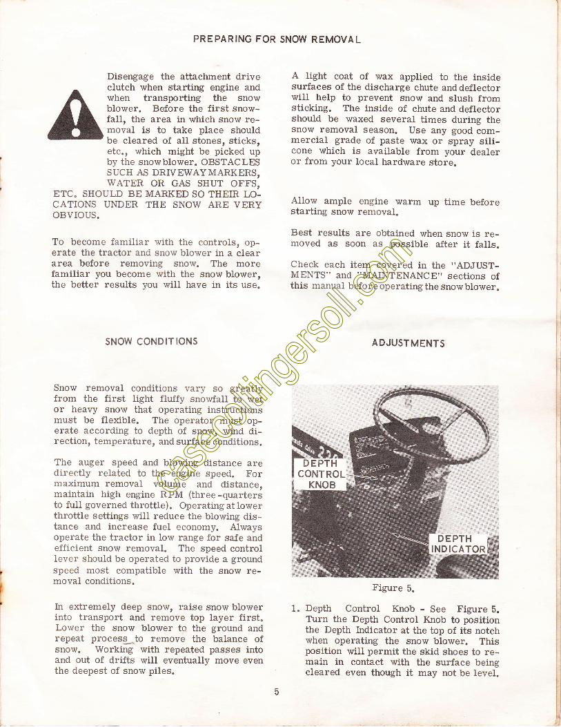
Figure 5.
1. Depth Control Knob - See Figure 5.Ttrrn the Depth Control Knob to positionthe Depth Indicator at the top of its notchwhen operating the snow blower. Thisposition will permit the skid shoes to re-main in contact with the surface beingcleared even though it may not be level.
DEPTHINDICATOR
AUGER DRIVE CHAINIDLER BOLT
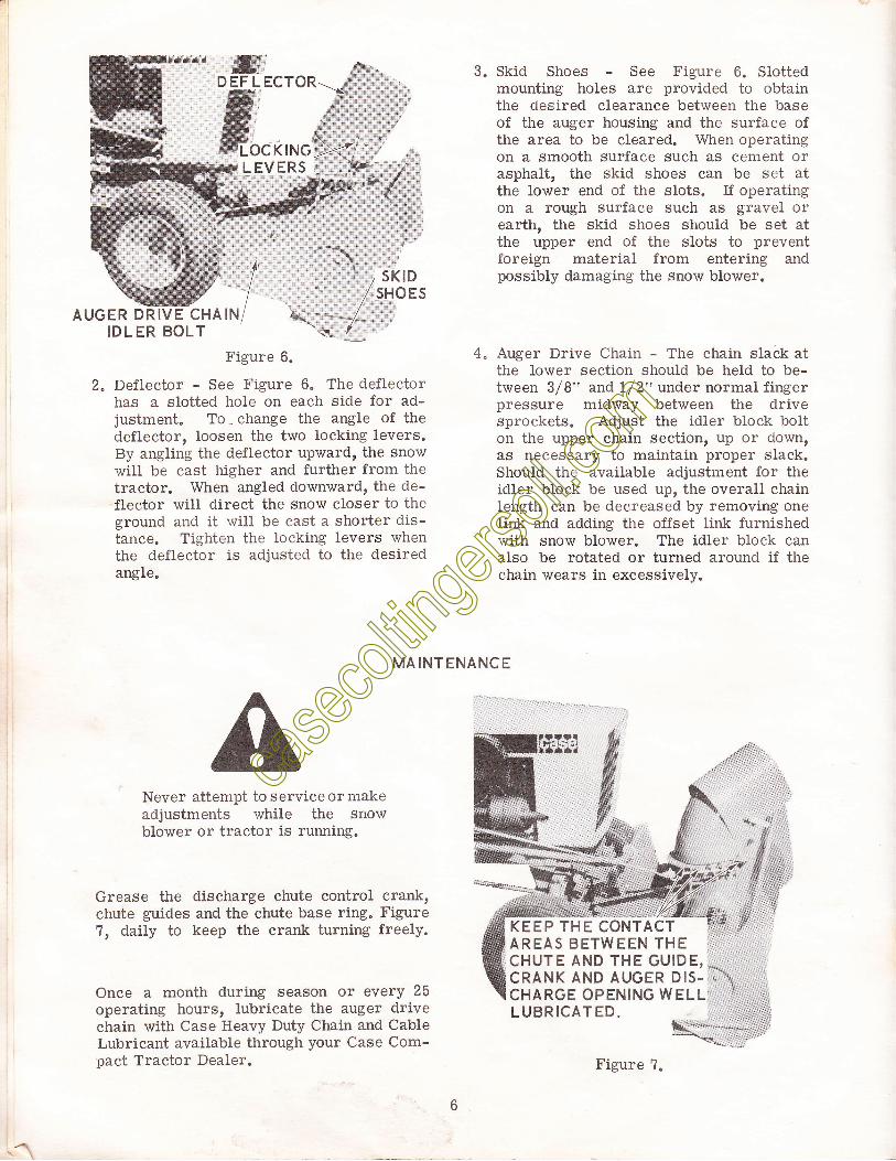
ryrD EF L ECTORffiffiffiLOC KING
L EVERS
Figure 6.
2" Deflector - See Figure 6. The deflectorhas a slotted hole on each side for ad-justment. To - change the angle of thedeflector, loosen the two Iocking levers.By angling the deflector upwardr the snowwill be cast higher and further from thetractor. When angled downward, the de-flector wili direct the snow closer to theground and it will be cast a shorter dis-tance. Tighten the locking levers whenthe deflector is adjusted to the desiredangle"
4,
'I1...I/q"
3. Skid Shoes - See Figure 6. Slottedmounting holes are provided to obtainthe oesired clearance between the baseof the auger housing and the surface ofthe area to be cleared. When operatingon a smooth surface such as cement orasphalt, the skid shoes can be set atthe lower end of the slots. ff operatingon a rough surface such as gravel orearth, the skid shoes should be set atthe upper end of the slots to preventforeign material from entering andpossibly damaging the snow blower.
4" Auger Drive Chain - The chain slack atthe lower section should be held to be-tween 3/8" and 1/2" under normal fingerpressure midway between the drivesprockets. Adjust the idler block bolton the upper chain section, up or down,as necessary to maintain proper slack.Should the available adjustment for theidler block be used up, the overall chainIength can be decreased by removing oneIink and adding the offset link furnishedwith snow blower. The idler block canalso be rotated or turned around if thechain wears in excessively.
MAINTENANCE
Never attempt to service or makeadjustments while the snowblower or tractor is running.
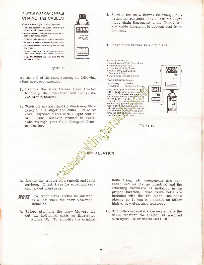
Grease the discharge chute control crank,chute guides and the chute base ring. Figure1, daily to keep the crank turning freely.
Once a month during season or every 25
operating hours, lubricate the auger drivechain with Case Heavy Duty Chain and CableLubricant available through your Case Com-oact Tractor Dealer.
rc @tff;:irjrjrJJir:tJtiJr jti J:7"::irird
KEEP THE CONTACTAREAS BETWEEN THECHUTE AND THE GUIDE, *CRANK AND AUGER DIS- .-A1
CHARGE OPENING WELL :
LUBRTCATED x* -. ,
E---
Figure 7.
--rf
A LITTLE DIRT CAN CRIPPLE
CHAINS and CABLESCheck these high quality features:. Provides constant lubri€tion, p€rmining a
smmth running chain or €ble. Allows maimum load carrying capacrtaes on
high or low sp6ed chains.
. Reduces lrictaon drags on sudden overloads
. Preventsdripping on slow speed or idle cha,ns
. Penetrates inward-llows freely into the linksand strands.
. Serues the purpo* ol a high quality.ust preventive to exmsed o( idle chains and cables
. Helps prevent cable and chain breakage andoremature failure.
Figure B.
At the end of the snow season, the followingsteps are recommended:
1. Remove the snorv blo.,ver from tractorfollowing the procedure outlined at theend of this manual.
2. Wash off any salt deposit which may havedried on the auger and chute. Paint orcover exposed metal with a light coat ofoil. Case Touch-up Enamel is avail-able through your Case Compact Trac-tor Dealer.
3. Service the snow blower following lubri-cation instructions above. Oil the augerdrive chain thoroughly using Case Chainand cable Lubricant to prevent rust fromforming.
4" Store snow blower in a dry place.
. Giossier Than lv'iost
. Gloss Lives on Whrle Other Chalk
. Matches Original Parnl
. Exceptional Hiding Power
. Same Formula As OngrnalEquipment Paint
. Outstanding Package Siaortrry
CASE PAINT is ToughStays Glossy ls StableHides Better Matches the Or grnat
Case Paint goes to Florida to rooxb€tter longer. After a pajnt samplepasses the Case weathercmeter cy-cle, it must endure a more severetest In sunny Flo|da In lhe sub-troprcal regron, West ol Miamr, thedeteriorating action of high tempera-ture, relative humrdity, annual rarn-fall. salt atmosphere and solar raora-tion combine to attack Case parnrOnly the best paints suryive to earnthe "Genuine" Case Lab€l
Figure 9.
INSTALLATION
A. Locate the tractor on a smooth and levelsurface. Check tires for equal and rec-ommended pressures.
t|lE The^^front tires should be inflatedto 20 nsi when the snow blower isinstallld.
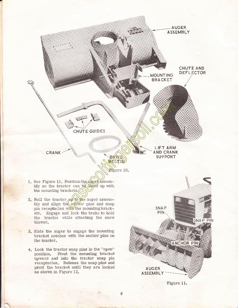
B. Before attaching the snow blower, layout the individual parts as illustratedir1 Figure 10. To simplify the original
installation, aII components are pre-assembled as far as practical and theattaching hardware is installed in itsproper location. Two drive belts areincluded with the 48" Model HB4 snowblower so it can be mounted on eitherhigh or low clearanee tractors.
C. The following installation sequence is thesame whether the tractor is equippedwith hydraulic or mechanical lift.
F
\
.z:
::
\ ontvsBELr(S)
Figure 1
LIFT ARMAND CRANK
SUPPORT
SNA PPIN
CHUTE ANDD EF L ECTOR
\
ANCHOR PIN
*MOUNTINGi ERICKET
G*\., CHUTE GUIDES
\..
CRANK /'- \ \
0.
1 See Figure 11. Position the auger assem-bly so the tractor can be lined up withthe mounting brackets"
RolI the tractor up to the auger assem-bly and align the anchor pins and snappin receptacles rvith the mountingbrack-ets. Engage and lock the brake to holdthe tractor while attachins the snowblower.
Slide the auger to engage the mountingbracket notches with the anchor pins onthe tractor.
Lock the tractor snap pins in the "open"position. Pivot the mounting bracketupward and into the tractor snap pinreceptacles. Release the snap pins andpivot the bracket until they are lockedas shown in Figure 12.
,-ffi
ffiAP PIN
3.
4"
Figure 11.
AUGER
CHUTE AND-DEFLEcToR
HEX HEAD
CRANKSPIROL
8.5.
9.6.
10.
Figure 12.
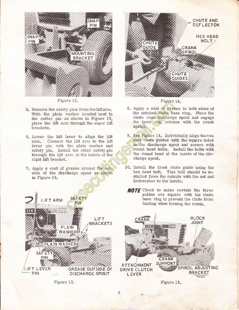
Remove the safety pins fromtheliftarm.With the plain washer located next tothe cotter pin as shown in Figure 13,place the lift arm through the auger liftbrackets.
Iower the lift lever to align the liftarm. Connect the lift arm to the liftlever pin with the plain washer andsafety pin. i::stall the other safety pinthrough the lift arm at the inside of theright lift bracket.
?. Apply a coat of grease around the out-side of the discharge spout as shownin Figure 13.
LIFT ARM 5AF ETYPIN
LIFT
PLAINWASHER
PLAIN WASHER
GREASEDISCHARGE SPOUT
Figure 13.
Figure 14.
Apply a coat of grease to both sides ofthe notched chute base ring. Place thechute over discharge spout and engagethe base ring notches with the crankspirol.
See Figure 14. Individualiy align thetwoside chute guides with the square holesin the discharge spout and secure withround head bolts. Install the bolts withthe round head at the inside of the dis-charge spout.
Install the front chute guide using thehex head bolt. This bolt should be in-stalled from the outside with the nut andlockwasher to the inside.
lQfE Check to make certain the threeguides are square with the chutebase ring to prevent the chute frombinding when turning the crank.
BLOCKJOINT
--'#RANK
:&\1
SUPPORTSPIROL ADJUSTING
BRACKETqd:;i$,,,,,,.
SAFPIN
ATTACHMENTDRIVE CLUTCH
L EVER
Figure 15.
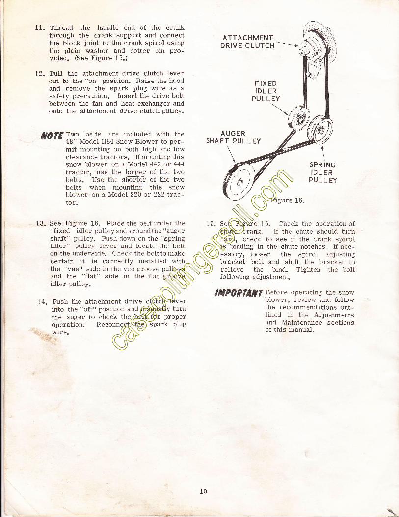
11. Thread the handle end of the crankthrough the crank support and connectthe block joint to the crank spirol usingthe plain washer and cotter pin pro-vided. (See Figure 15.)
12. PuIl the attachment drive clutch leverout to the "on" position. Raise the hoodand remove the spark plug wire as asafety precaution. Insert the drive beltbetween the fan and heat exchanger andonto the attachment drive clutch pulley.
JA]?'l''utn, holtg are included with thetv t 3 iti;:*"i.i H84 snow Blower to per-mit mounting on both hi.gh and lowclearance tractors. If mounting thissnow blower on a Model 442 or 444tractor, use the lgngq" of the twobelts. Use the shorter of the twobelts when mountlng tiris snowblower on a Model 220 or 222 ftac-tor.
13. See Figure 16. Place the belt under the"fixed" idler pulieyand aroundthe "augelshaft" pulley. Push down on the "springidler" pulley lever and locate the belton the underside. Check the belttomakecertain it is correctly installed withthe "vee" side in the vee groove pulleysand the "flat" side in the flat grooveidler pulley.
14. Push the attachment drive clutch leverinto the "off" position and manually turnthe auger to check the belt for properoperation. Reconnect the spark plugwire.
ATTACHMENTDRIVE CLUTCH -------i
F IXEDIDLER
PUL L EY
AUGERSHAFT PULLEY
Figure 16.
15. See Figure 15. Check the operation ofchute crank. If the chute should turnhard, check to see if the crank spirolis binding in the chute notches. If nee-essary, loosen the spirol adjustingbracket bolt and shift the bracket torelieve the bind. Tighten the boltfollowing adjustment.
HP0Pfltflt Before operating the snowblower, review and followthe recommendations out-Iined in the Adjustmentsand Maintenance sectionsof this manual.
\
SPRINGIDL ER
PUL L EY
l0
\
lI
I
REMOVING THE SNOW
1. Disconnect spark plug wire a_s a safetyprecaution, pull the attachment driveclutch lever out to the "on" position.
2. Push the "spring idler" puiley down toIoosen and remove the belt. Push theclutch lever back into the "off" positionand reconnect the spark plug wire.
REMOUNTING THE SNOW BLOWER
BLOWER
Disconnect the tift arm from the tractorIift lever. Remove the safety pin fromthe front of the lift arm. Slide the tiftarm part way out of the auger lift brack-ets to clear the tractor. Swing the liftarm with crank attached over the auserassembly.
Pull the snap pins out to release themountlng bracket and back the tractoraway.
:z
3. Disconnect spark plug wire as a safetyprecaution. PuIl the clutcfr lever outand install the belt as explained in para-graph 13 of the Installation Section.
low clearance tractor belt
High clearance tractor belt
3.
A
1.
,.
With brakes locked, slide auger assemblyto position mounting bracket slots ontothe anchor pins. Pivotthe mounting brack-et upward and engage the snap pins.
Connect lift arm to tractor lift lever andsecure with plain washers and safety pinsat both front and rear ends.
t0rEThe J I Case Company reserves theright to make improvements in de-sign or changes in specifications atany time without incurring any ob-Iigation to install them on unitspreviously sold.
AII of the information and instructions contained in the updated op-erators Manual for HBO and Hg4 snow blowers g-sb3Oi R-l oatidL0/22/71 are applicable to the J series snow blowers.
The significant change in the J series are longer drive belts to ac-commodate installation on 1973 model tractors. Fotlowing is the drivebelt cross reference chart for interchange installationbetweenH seriesand J series snow blowers.
HBO.C1649B
H84-C16499
JBO-C1B?06
J84-CtB?0?
Printed in U.S.A. 40d
11
"FJNBO
3ys.'_;!lINSTALLATION INSTRUC TION SUPPLEMENT
MoDEL HBo sNow BLowERS, s/N Fzota2 AND ABovE
H84 sNow BLowERs, s/N Gzlzol AND ABovE
4.1.
5.
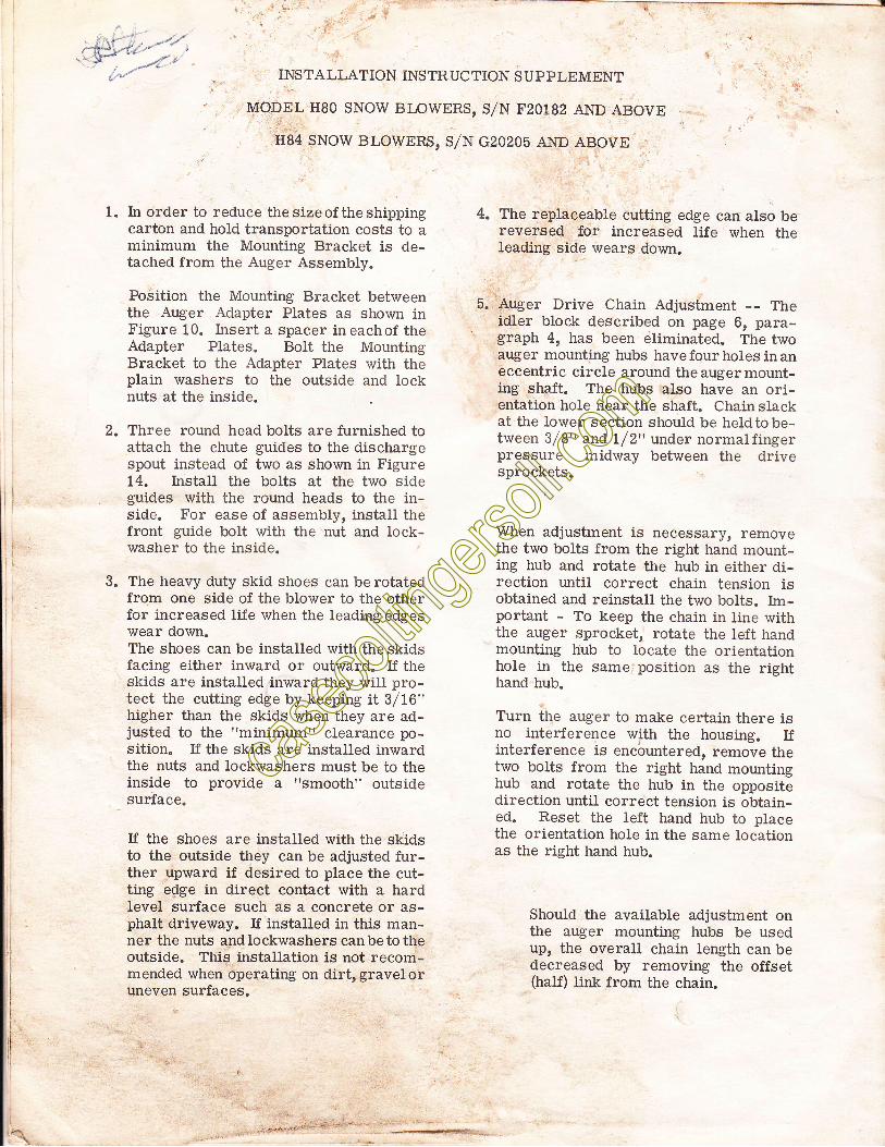
In order to reduce thesizeof theshippingcarton and hold transportation costs to aminimum the Mounting Bracket is de-tached from the Auger Assembly.
Position the Mounting Bracket betweenthe Auger Adapter P1ates as shown inFigure 10. hsert a spacer in eachof theAdapter Plates. Bolt the MountingBracket to the Adapter Plates with theplain washers to the outside and locknuts at the inside.
Three round head bolts are furnished toattach the chute guides to the dischargespout instead of two as shown in Figure14. InstaII the bolts at the two sideguides with the round heads to the in-side. For ease of assembly, install thefront guide boit with the nut and lock-washer to the inside.
The heavy duty skid shoes can be rotatedfrom one side of the blower to the otherfor increased life when the leading edgeswear down.The shoes can be installed with the skidsfacing either inward or outward. If theskids are installed inward they wiII pro-tect the cutting edge by keeping it 3/16"higher than the skids when they are ad-justed to the "minimum" clearance po-sition" If the skids are installed inwardthe nuts and lockwashers must be to theinside to provide a "smooth" outsidesuriace.
If the shoes are installed with the skidsto the outside they can be adjusted fur-ther upward if desired to place the cut-ting e$ge in direct contact with a hardlevel surface such as a concrete or as-phalt driveway. If installed in this man-ner the nuts andlockwashers canbetotheoutside. This installation is not recom-mended when operating on dirtrgraveloruneven surfaces.
The replaceable cutting edge can also bereversed for increased life when theleading side_ wears down.
Auger Drive Chain Adjustment -- Theidler block described on page 6, para-graph 4, has been eliminated. The twoauger mounting hubs have four holes in aneccentric circle around the auger mount-ing shaft. The hubs also have an ori-entation hole near the shaft. Chainslackat the lower section should be heldtobe-tween 3/8" and lf 2" under normalfingerpressure midway between the drivesprockets.
When adjustment is necessary, removethe two bolts from the right hand mount-ing hub and rotate the hub in either di-rection until correct chain tension isobtained and reinstall the two bolts. lm-portant - To keep the ehain in line withthe auger sprocket, rotate the left handmounting hub to locate the orientationhole in the same position as the righthand hub.
Turn the auger to make certain there isno interference with the housing. Ifinterference is encountered, remove thetwo bolts from the right hand mountinghub and rotate the hub in the oppositedirection until correct tension is obtain-ed. Reset the left hand hub to placethe orientation hole in the same locationas the right hand hub.
Should the available adjustment onthe auger mounting hubs be usedup, the overall chain length can bedecreased by removing the offset(half) lirk from the chain.
,
il
ii
3.
t
.,j