ix series - aiphone · ix series ix-1as / ix-10as 2-wire network adaptor installation &...
TRANSCRIPT
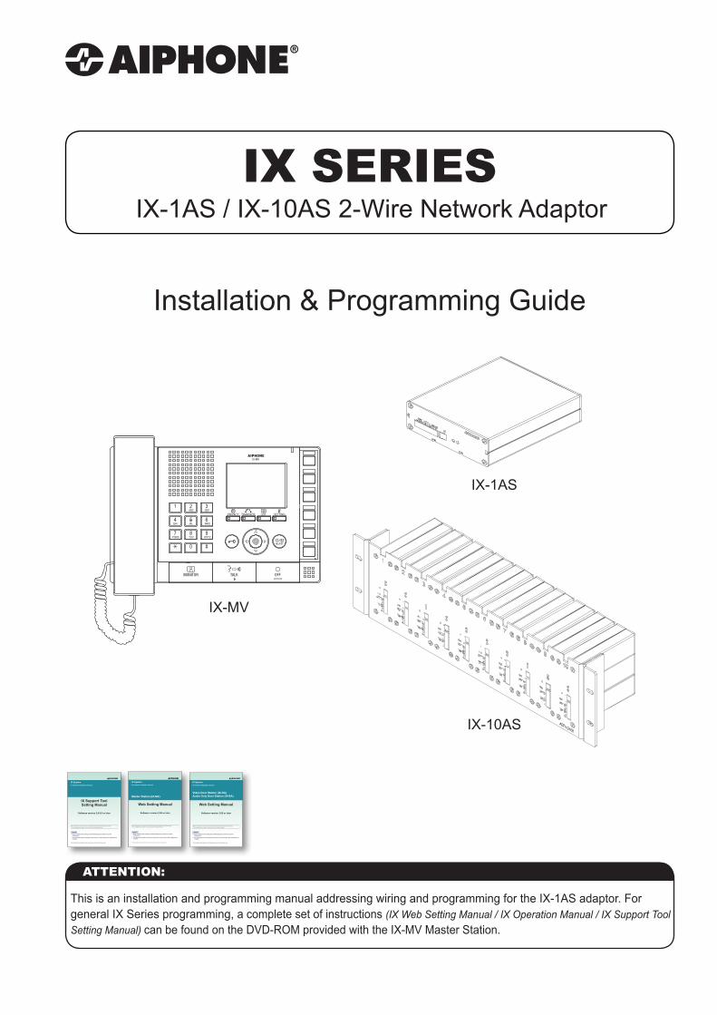
IX SERIESIX-1AS / IX-10AS 2-Wire Network Adaptor
Installation & Programming Guide
This is an installation and programming manual addressing wiring and programming for the IX-1AS adaptor. For general IX Series programming, a complete set of instructions (IX Web Setting Manual / IX Operation Manual / IX Support Tool Setting Manual) can be found on the DVD-ROM provided with the IX-MV Master Station.
ATTENTION:
IX SystemIP network-compatible intercom
Video Door Station (IX-DA)Audio Only Door Station (IX-BA)
Web Setting Manual
Software version 2.00 or later
Important
Begin installation after reading and understanding the procedures for system configuration.The setting data should be backed up and stored in a safe location after configuration is complete.
The illustrations and images in this manual may vary from the actual ones.
Before configuring and using the system, read Setting Manual and Operation Manual (PDF) carefully.*For the installation and connection of each device, refer to Installation Manual.
IX SystemIP network-compatible intercom
Master Station (IX-MV)
Web Setting Manual
Software version 2.00 or later
Important
Begin installation after reading and understanding the procedures for system configuration.The setting data should be backed up and stored in a safe location after configuration is complete.
The illustrations and images in this manual may vary from the actual ones.
Before configuring and using the system, read Setting Manual and Operation Manual (PDF) carefully.*For the installation and connection of each device, refer to Installation Manual.
IX SystemIP network-compatible intercom
IX Support ToolSetting Manual
Software version 2.0.0.0 or later
Important
Begin installation after reading and understanding the procedures for system configuration.The setting data should be backed up and stored in a safe location after configuration is complete.
The illustrations and images in this manual may vary from the actual ones.
Before configuring and using the system, read Setting Manual and Operation Manual (PDF) carefully.*For the installation and connection of each device, refer to Installation Manual.
SETTING
1
4GHI
7PQRS
#0
ABC
JKL
TUV
5
8
2
6
9WXYZ
MNO
3DEF
TRANSFERPRIVACY LIST
IX-MV
IX-1AS
IX-10AS
2 | IX-1AS Installation & Programming Guide
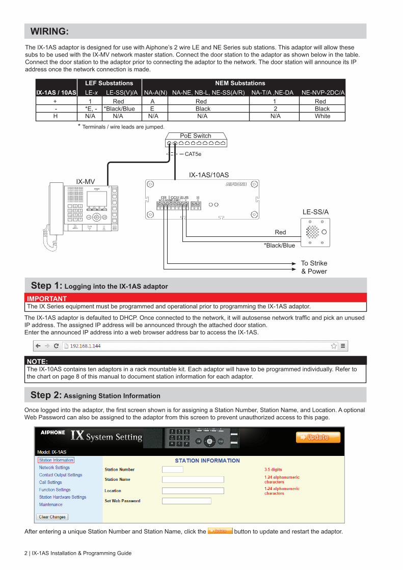
Step 1: Logging into the IX-1AS adaptor
The IX-1AS adaptor is designed for use with Aiphone’s 2 wire LE and NE Series sub stations. This adaptor will allow these subs to be used with the IX-MV network master station. Connect the door station to the adaptor as shown below in the table. Connect the door station to the adaptor prior to connecting the adaptor to the network. The door station will announce its IP address once the network connection is made.
The IX-1AS adaptor is defaulted to DHCP. Once connected to the network, it will autosense network traffic and pick an unused IP address. The assigned IP address will be announced through the attached door station.Enter the announced IP address into a web browser address bar to access the IX-1AS.
Step 2: Assigning Station Information
Once logged into the adaptor, the first screen shown is for assigning a Station Number, Station Name, and Location. A optional Web Password can also be assigned to the adaptor from this screen to prevent unauthorized access to this page.
After entering a unique Station Number and Station Name, click the button to update and restart the adaptor.
IX-1AS/10AS
LE-SS/A
Red
*Black/Blue
PoE Switch
SETTING
1
4GHI
7PQRS
#0
ABC
JKL
TUV
5
8
2
6
9WXYZ
MNO
3DEF
TRANSFERPRIVACY LIST
IX-MV
CAT5e
To Strike & Power
IX-1AS / 10AS LE-x LE-SS(V)/A NA-A(N) NA-NE, NB-L, NE-SS(A/R) NA-T/A ,NE-DA NE-NVP-2DC/A + 1 Red A Red 1 Red - *E, - *Black/Blue E Black 2 Black H N/A N/A N/A N/A N/A White
LEF Substations NEM Substations
* Terminals / wire leads are jumped.
WIRING:
IMPORTANT:The IX Series equipment must be programmed and operational prior to programming the IX-1AS adaptor.
NOTE:The IX-10AS contains ten adaptors in a rack mountable kit. Each adaptor will have to be programmed individually. Refer to the chart on page 8 of this manual to document station information for each adaptor.
3
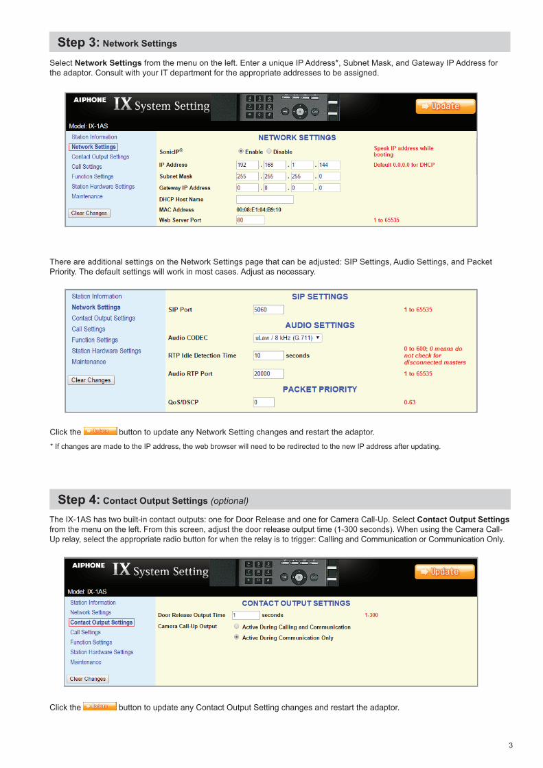
Step 3: Network Settings
Step 4: Contact Output Settings (optional)
Select Network Settings from the menu on the left. Enter a unique IP Address*, Subnet Mask, and Gateway IP Address for the adaptor. Consult with your IT department for the appropriate addresses to be assigned.
There are additional settings on the Network Settings page that can be adjusted: SIP Settings, Audio Settings, and Packet Priority. The default settings will work in most cases. Adjust as necessary.
Click the button to update any Network Setting changes and restart the adaptor.
The IX-1AS has two built-in contact outputs: one for Door Release and one for Camera Call-Up. Select Contact Output Settings from the menu on the left. From this screen, adjust the door release output time (1-300 seconds). When using the Camera Call- Up relay, select the appropriate radio button for when the relay is to trigger: Calling and Communication or Communication Only.
Click the button to update any Contact Output Setting changes and restart the adaptor.
* If changes are made to the IP address, the web browser will need to be redirected to the new IP address after updating.
4 | IX-1AS Installation & Programming Guide
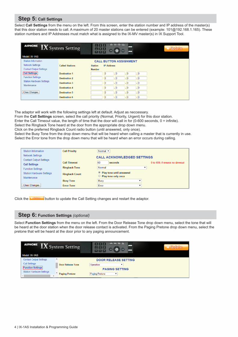
Step 5: Call SettingsSelect Call Settings from the menu on the left. From this screen, enter the station number and IP address of the master(s) that this door station needs to call. A maximum of 20 master stations can be entered (example: [email protected]). These station numbers and IP Addresses must match what is assigned to the IX-MV master(s) in IX Support Tool.
The adaptor will work with the following settings left at default. Adjust as neccessary.From the Call Settings screen, select the call priority (Normal, Priority, Urgent) for this door station. Enter the Call Timeout value, the length of time that the door will call in for (0-600 seconds, 0 = infinite). Select the Ringback Tone heard at the door from the appropriate drop down menu. Click on the preferred Ringback Count radio button (until answered, only once). Select the Busy Tone from the drop down menu that will be heard when calling a master that is currently in use. Select the Error tone from the drop down menu that will be heard when an error occurs during calling.
Click the button to update the Call Setting changes and restart the adaptor.
Step 6: Function Settings (optional)
Select Function Settings from the menu on the left. From the Door Release Tone drop down menu, select the tone that will be heard at the door station when the door release contact is activated. From the Paging Pretone drop down menu, select the pretone that will be heard at the door prior to any paging announcement.
5
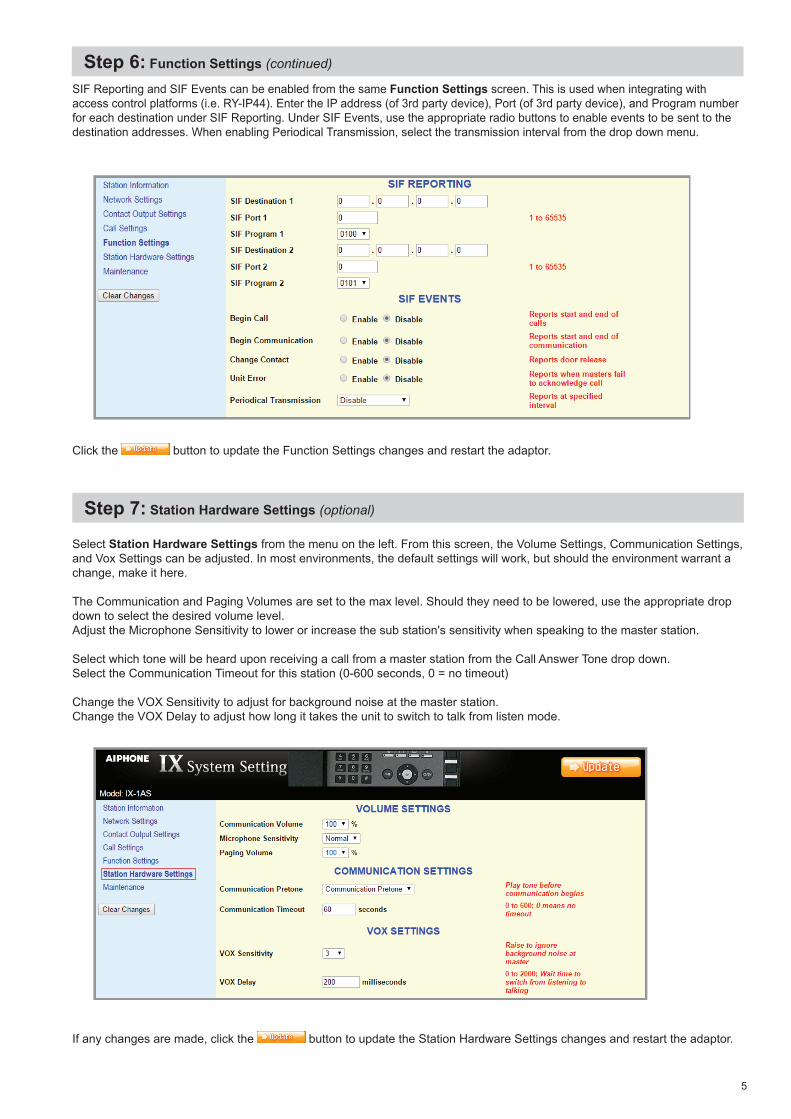
Step 6: Function Settings (continued)
SIF Reporting and SIF Events can be enabled from the same Function Settings screen. This is used when integrating with access control platforms (i.e. RY-IP44). Enter the IP address (of 3rd party device), Port (of 3rd party device), and Program number for each destination under SIF Reporting. Under SIF Events, use the appropriate radio buttons to enable events to be sent to the destination addresses. When enabling Periodical Transmission, select the transmission interval from the drop down menu.
Click the button to update the Function Settings changes and restart the adaptor.
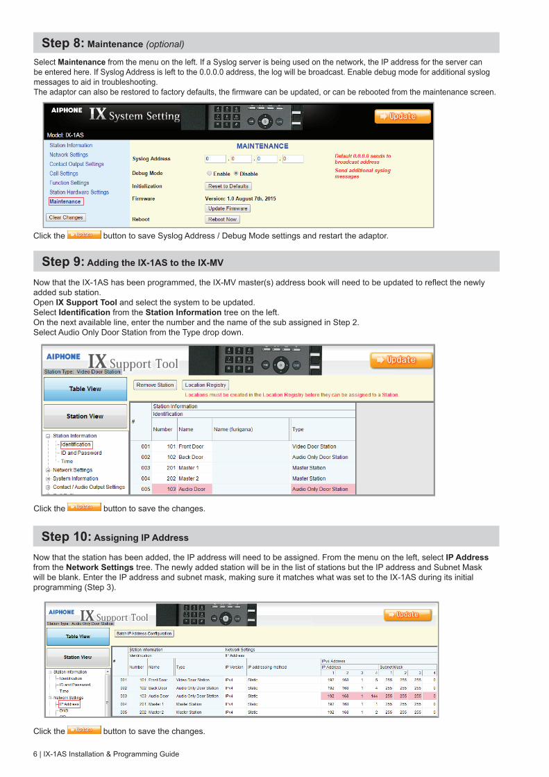
Step 7: Station Hardware Settings (optional)
Select Station Hardware Settings from the menu on the left. From this screen, the Volume Settings, Communication Settings, and Vox Settings can be adjusted. In most environments, the default settings will work, but should the environment warrant a change, make it here. The Communication and Paging Volumes are set to the max level. Should they need to be lowered, use the appropriate drop down to select the desired volume level.Adjust the Microphone Sensitivity to lower or increase the sub station's sensitivity when speaking to the master station.
Select which tone will be heard upon receiving a call from a master station from the Call Answer Tone drop down. Select the Communication Timeout for this station (0-600 seconds, 0 = no timeout)
Change the VOX Sensitivity to adjust for background noise at the master station.Change the VOX Delay to adjust how long it takes the unit to switch to talk from listen mode.
If any changes are made, click the button to update the Station Hardware Settings changes and restart the adaptor.
6 | IX-1AS Installation & Programming Guide
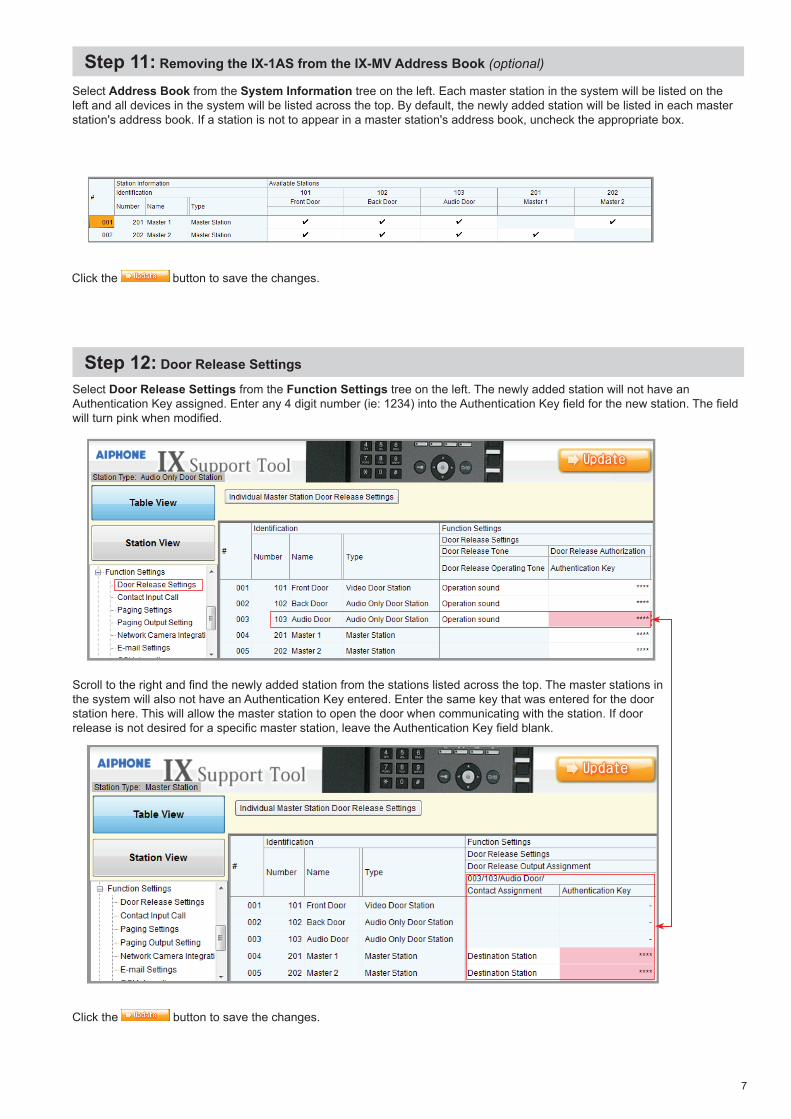
Step 8: Maintenance (optional)
Select Maintenance from the menu on the left. If a Syslog server is being used on the network, the IP address for the server can be entered here. If Syslog Address is left to the 0.0.0.0 address, the log will be broadcast. Enable debug mode for additional syslog messages to aid in troubleshooting.The adaptor can also be restored to factory defaults, the firmware can be updated, or can be rebooted from the maintenance screen.
Step 9: Adding the IX-1AS to the IX-MV
Now that the IX-1AS has been programmed, the IX-MV master(s) address book will need to be updated to reflect the newly added sub station. Open IX Support Tool and select the system to be updated.Select Identification from the Station Information tree on the left. On the next available line, enter the number and the name of the sub assigned in Step 2. Select Audio Only Door Station from the Type drop down.
Click the button to save the changes.
Step 10: Assigning IP Address
Now that the station has been added, the IP address will need to be assigned. From the menu on the left, select IP Address from the Network Settings tree. The newly added station will be in the list of stations but the IP address and Subnet Mask will be blank. Enter the IP address and subnet mask, making sure it matches what was set to the IX-1AS during its initial programming (Step 3).
Click the button to save the changes.
Click the button to save Syslog Address / Debug Mode settings and restart the adaptor.
7
Select Address Book from the System Information tree on the left. Each master station in the system will be listed on the left and all devices in the system will be listed across the top. By default, the newly added station will be listed in each master station's address book. If a station is not to appear in a master station's address book, uncheck the appropriate box.
Click the button to save the changes.
Step 11: Removing the IX-1AS from the IX-MV Address Book (optional)
Step 12: Door Release Settings
Click the button to save the changes.
Select Door Release Settings from the Function Settings tree on the left. The newly added station will not have an Authentication Key assigned. Enter any 4 digit number (ie: 1234) into the Authentication Key field for the new station. The field will turn pink when modified.
Scroll to the right and find the newly added station from the stations listed across the top. The master stations in the system will also not have an Authentication Key entered. Enter the same key that was entered for the door station here. This will allow the master station to open the door when communicating with the station. If door release is not desired for a specific master station, leave the Authentication Key field blank.
8 | IX-1AS Installation & Programming Guide
SpecificationsPower: Power-over-Ethernet (IEEE 802.3af, class 0)Current Consumption: Maximum 250mA per IX-1ASDoor Release Relay: 24VDC, 500mACamera Call Up Relay: 24VDC, 500mACommunication: Hands-free Half duplex, VOXLAN: Ethernet (10BASE-T, 100BASE-TX)Audio Codec: G.711Protocol: IPv4, TCP, UDP, SIP, HTTP, RTP, RTCP, IGMP, DHCPOperating Temperature: 32°F ~ 122°F (0°C ~ 50°C)Material: Aluminum (IX-1AS) Steel (IX-10AS)Color: Silver (IX-1AS) Black (IX-10AS)Dimensions: 1-½” H x 4-¼” W x 4-15⁄16” D (IX-1AS) 5-¼” H x 16-¾” W x 4-15⁄16” D (IX-10AS)
Aiphone Corporation | www.aiphone.com/home | [email protected] | P: 800.692.0200
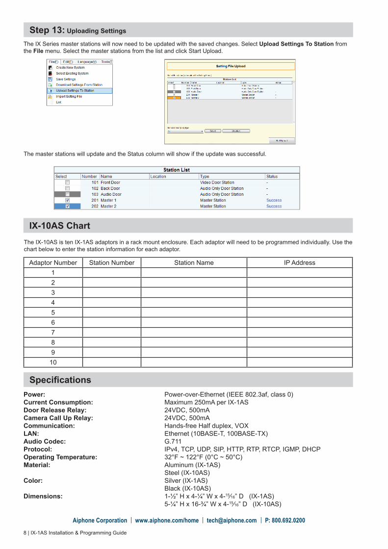
The IX Series master stations will now need to be updated with the saved changes. Select Upload Settings To Station from the File menu. Select the master stations from the list and click Start Upload.
Step 13: Uploading Settings
The master stations will update and the Status column will show if the update was successful.
IX-10AS ChartThe IX-10AS is ten IX-1AS adaptors in a rack mount enclosure. Each adaptor will need to be programmed individually. Use the chart below to enter the station information for each adaptor.
Adaptor Number Station Number Station Name IP Address12345678910