iuid-enabled serialized item management in operations and ... · iuid-enabled serialized item...
TRANSCRIPT

IUID-Enabled Serialized Item Management in Operations and Maintenance
Logistics IUID Task Force
November 2011

IUID-Enabled Serialized Item Management in Operations and Maintenance
Author:Logistics IUID Task Force
LMI Point of Contact: Ronald G. Nolte
November 2011

iii
Contents
BENEFITS OF IUID IMPLEMENTATION ................................................................................... 1SERIALIZED ITEM MANAGEMENT FOR MATERIEL MAINTENANCE ............................................. 3USES OF IUID-ENABLED SIM IN MAINTENANCE .................................................................... 4CATEGORIZING MAINTENANCE INTO LEVELS ......................................................................... 5O-LEVEL IUID-ENABLED SIM ............................................................................................. 7
Capturing and Recording O-Level Use and Preventative Maintenance ..................... 7Capturing and Recording O-Level Corrective Maintenance ....................................... 9Capturing and Recording O-Level QA/QC and Safety Inspections .......................... 10O-Level IUID-Enabled SIM in Maintenance Process in Action ................................. 11
I-LEVEL IUID-ENABLED SIM ............................................................................................. 14Capturing and Recording I-Level Preventative Maintenance ................................... 14Capturing and Recording I-Level Corrective Maintenance ....................................... 16Capturing and Recording I-Level QA/QC and Safety Inspections ............................ 17I-Level IUID-Enabled SIM in Maintenance Process in Action .................................. 18
D-LEVEL IUID-ENABLED SIM ........................................................................................... 19Capturing and Recording the Induction of Items into Depot Maintenance ............... 19Capturing and Recording D-Level Maintenance in Back Shops .............................. 20Capturing and Recording D-Level Piece Part Maintenance and Sourcing ............... 21Capturing and Recording D-Level Maintenance Reassembly .................................. 22Final Assembly in Depot Maintenance ..................................................................... 23D-Level IUID-Enabled SIM in Maintenance Process in Action ................................. 24
IUID DISCREPANCIES DISCOVERED DURING MAINTENANCE ................................................. 26Resolving Physical Mark Errors ............................................................................... 28Resolving Data Errors .............................................................................................. 28
APPENDIX A. IUID TASK FORCE REQUIREMENTS FOR INTERMEDIATE MAINTENANCE
APPENDIX B. IUID TASK FORCE REQUIREMENTS FOR DEPOT MAINTENANCE
APPENDIX C. PROCESS MAPS LEGEND
APPENDIX D. IUID-ENABLED SIM IN MAINTENANCE PROCESS MAPS
APPENDIX E. ABBREVIATIONS

iv
FIGURES
Figure 1. DoD Maintenance Construct ....................................................................... 6Figure 2. Capturing and Recording O-Level Use and Preventive Maintenance ......... 8Figure 3. Capturing and Recording O-Level Corrective Maintenance ...................... 10Figure 4. Capturing and Recording O-Level QA/QC and Safety Inspections ........... 11Figure 5. Capturing and Recording I-Level Preventative Maintenance .................... 15Figure 6. Capturing and Recording I-Level Corrective Maintenance ........................ 16Figure 7. Routing Materiel to Back Shops or Higher Maintenance .......................... 17Figure 8. Capturing and Recording I-Level QA/QC and Safety Inspections ............. 17Figure 9. Capturing and Recording the Induction of Items
into Depot Maintenance ...................................................................................... 20Figure 10. Capturing and Recording D-Level Maintenance in Back Shops ............. 21Figure 11. Capturing and Recording D-Level Piece Part Maintenance
and Sourcing ...................................................................................................... 22Figure 12. Capturing and Recording D-Level Reassembly ...................................... 23Figure 13. Final Assembly and Quality Assurance in Depot
Maintenance Process ......................................................................................... 24Figure 14. Resolving Physical Marking Errors ......................................................... 28Figure 15. Resolving Data Errors ............................................................................. 31

1
IUID-Enabled Serialized Item Management in Operations and Maintenance
In its June 2010 report1
The report went on to recommend the Department target for IUID implementation items whose item-level traceability and management bring the greatest value to DoD in three areas:
to the Joint Logistics Board, the Logistics Item Unique Identification (IUID) Task Force highlighted the great potential and value of us-ing IUID in the logistics areas of the Department of Defense. The report recom-mended IUID be implemented as soon as is practicable, as the benefits are substantial.
Product lifecycle management (PLM)
Intensive item management (IIM)
Property accountability (PA).
BENEFITS OF IUID IMPLEMENTATION The task force found numerous examples of increased efficiency and capability in each of these areas when automated practices, condition-based maintenance, and IUID-enabled serialized item management (SIM) were enabled.
In the area of PLM, using unique item identification (UII) for SIM results in more timely, accurate, reliable, and actionable information. UII for SIM also improves maintenance and materiel management. These benefits derive from harvesting the serial item data through IUID and utilizing the data to make PLM programs (such as reliability, availability, and maintainability [RAM] analysis) more effective. Using IUID to enable SIM can achieve significant RAM, readiness, and materiel management improvements and reduce safety and other risks.
IIM requires automated processes to decrease the risk of human error and to faci-litate more frequent and expedited inventories of items that are intensively ma-naged because of their sensitivity. A standard approach to SIM will improve the management of these items across all supply chain nodes. The IUID program en-hances current SIM programs by standardizing previously disparate serial number schemas into a globally unique identification program and using a standard machine-readable mark for all IUID-eligible items procured by DoD. UII, when
1 Implementation of Item Unique Identification in DoD Logistics Processes, Logistics Item
Unique Identification Task Force, June 8, 2010.

2
correctly assigned and maintained, provides the granularity of information neces-sary to correctly manage this population of sensitive items.
Users at the base level often make item identification errors; in fact, item identifi-cation can be so technically complex that correct identification requires a certified engineer. A machine-readable UII would rectify this issue. Implementation of an IUID program and the integrated procedures will provide DoD with the means for enhancing its IIM capability throughout the Department by significantly decreas-ing the potential for human error and confusion. Managers of these types of items have consistently emphasized the value that DoD-wide implementation of an IUID program and standard procedures would provide.
The task force expects that business benefits will be realized by each supply chain node as a byproduct of IIM. Items within four categories—nuclear weapons–related materiel and classified, sensitive, and critical safety items—often carry a high price tag, so managing them would prevent substantial financial losses. Of course, financial benefits are not the primary focus of this value chain. The cost of not implementing an IUID or SIM program includes the potential loss of critical items and military-unique technology. The benefits of implementation include the strict accountability and control of the Department’s most critical assets to ensure the security and safety of these assets.
In the area of PA, the benefits of IUID-enabled SIM includes making the required linkage of Department- and component-level financial and logistics data, thus im-proving the availability of mission-critical information to acquisition decision makers, better equipping the armed forces for missions, and complying with fed-eral regulations, the law, and DoD policy. Other expected benefits include ensur-ing better control over government property.
The enterprise-level implementation of IUID will permit the tracking of military equipment and general equipment assets across their lifecycle by tying them to accountable property officers in accountable property systems of record (which link to custodial owners, location, condition, status, inventory history, and histori-cal maintenance and warranty-related information). As an example, unique identi-fication will ensure the military services’ staffs and commanders know which assets they control and the related maintenance and supply history of those assets. Once condition and location information is available at an enterprise-level, deci-sions can be made about cross-leveling equipment and finding replacements near at hand, which may help to replace losses faster. Information on assets controlled and their condition would also be available to commanders at the battalion-level in the Army and Marine Corps and at the wing-level in the Air Force and Navy. When physical asset records are linked to financial asset records, information about asset value and the remaining useful life could be accessible as well.
Finally, the use of automated information technology and systems (AIT/AIS) will improve the accuracy of information recorded on equipment assets and will strengthen the components’ ability to achieve greater accuracy with physical

3
inventories. The use of AIT/AIS will also decrease the time and cost to complete physical inventories.
SERIALIZED ITEM MANAGEMENT FOR MATERIEL MAINTENANCE
Serialized item management for materiel maintenance is prescribed in DoD In-struction (DoDI) 4151.19. That instruction requires the military departments and defense agencies to
identify populations of select items (parts, components, and end items);
mark all items in each population with a unique item identifier; and
generate, collect, and analyze maintenance, logistics, and usage data about each specific item.
The intent is to develop a broad-based, data-rich enterprise capability that leve-rages automation to easily produce error-free item-related data that is compatible and interoperable across military departments and defense agencies. The goals of SIM are to
improve the effectiveness and efficiency of DoD design, procurement, manufacturing, maintenance, and logistics operations;
improve weapons system readiness, reliability, and safety; and
reduce ownership costs.
A key element of SIM is unique identification of items. It is necessary to have a unique identifier for each instance of a particular item so that it can be distinguished from another like item. Thus, the unique attributes of that item can be compared with attributes of similar items to measure its performance against design specifica-tions, to assess reliability and maintainability attributes, and to eliminate bad actors. The Department has determined that this unique identifier is the IUID.2
Physically, IUID is a machine-readable UII applied to property that meets pre-scribed criteria.
3
In maintenance, this ability allows maintainers and artisans to launch electronic maintenance procedures, technical data, and item attributes (such as repair history and life remaining) to perform precise maintenance and make repair decisions
The UII allows for the unambiguous automated identification of a certain instance of a particular item. It also enables an ability to automate access to computer-based information about the item.
2 DoD Directives 8320.03 and 8320.04, along with the DoD Guide to Uniquely Identified
Items describes the specific details of IUID. 3 DoDI 8320.04 prescribes IUID criteria.

4
specific to the unique item in the maintenance process. By scanning the UII, oper-ators, crews, and maintainers launch electronic item attributes for review and up-date. They also order repair parts, and record maintenance actions electronically. Configuration information is updated and recorded through UII scans, and de-tailed maintenance procedures and technical data (those relevant to the unique item in maintenance) can be launched electronically. These and other automated functions are enabled by the automated identification of unique items.
External to the maintenance domain, the enterprise relies on maintenance as the foundation to record and report weapon system performance. Data richness, accu-racy, and reliability are improved tremendously by IUID-enabled SIM. Accurate identification of items and their condition, as determined by maintenance, im-proves distribution of items within the supply chain. With better visibility of item attributes, reliability engineers and logistics analysts can better access accurate and timely data about specific items or populations of items to analyze perfor-mance, identify material problems and solutions, and improve reliability, maintai-nability, design, and weapon system availability.
The IUID task force validated the requirements for field and depot maintenance based on existing policy and analysis. These requirements align to the uses of IUID in maintenance. The primary focus of the task force requirements, in both field and depot maintenance, can be grouped into three categories: policy, plan-ning, and management. This grouping allows for a systematic approach to imple-menting, monitoring, and controlling tangible items of personal property. Once the initial policy and planning activities are completed and execution of the pro-gram has begun, progress of the work can be tracked, monitored, and controlled regularly via the identified management requirements. A full description of the requirements associated with each category can be found in Appendix A for in-termediate maintenance and Appendix B for depot maintenance.
Visibility of items and materiel within the maintenance environment aligns with visibility requirements for other business, logistics, and operational processes and functions. In addition, the enterprise relies on maintenance to determine the con-dition of items and materiel. Therefore, the achievement of accurate and reliable visibility of materiel within maintenance information systems is critical to other materiel management systems, processes, and procedures used throughout DoD.
USES OF IUID-ENABLED SIM IN MAINTENANCE The task force identified six fundamental uses of IUID-enabled SIM in mainten-ance. This document focuses on the visibility and attributes of SIM items and how IUID improves the accuracy of this visibility, which also improves the effective-ness and efficiency of maintenance. It is important that this visibility penetrates the maintenance environment and item attributes are considered in the mainten-ance processes, updated when affected by maintenance functions, and accurately rec-orded for use across the enterprise. Because the focus is on improving maintenance

5
through item visibility and attributes, we have identified fundamental uses of IUID-enabled SIM in the maintenance processes at each level where visibility or attributes can enhance the process or where they are affected in similar ways. This allows us to focus on IUID-enabled precision maintenance rather than on the maintenance levels themselves.
Maintenance uses the UII to electronically
associate operators and maintainers to the items they operate and maintain,
validate that operators and maintainers are certified on the items they are operating and maintaining,
launch maintenance procedures and technical data,
update parent-child relationships (i.e., configuration) during disassembly and assembly,
record and report the custody and condition of items in maintenance, and
record maintenance and inspection at the point of maintenance (location, time, and date) as it occurs.
It is important to note that these six fundamental uses of IUID-enabled SIM facili-tate precision maintenance through automated data access and data gathering. It is the richness of the data and ease in accessing that data that improve the efficiency and effectiveness of maintenance, equipment availability, and the greater logis-tics enterprise.
CATEGORIZING MAINTENANCE INTO LEVELS Maintenance4 can be categorized in a finite number of levels. The materiel, in-formation, labor, technical data, and associated equipment, parts, and processes used in sustaining a given level of readiness, capability, condition, or performance can be aligned to these maintenance levels.5
4 Maintenance is any materiel repair activity, organization, operation, facility, or their asso-
ciated systems and processes designed to retain materiel in a serviceable condition or restore mate-riel to a serviceable condition.
For example, preparing a specific piece of equipment for operations holds to the same essential process and out-come for the Army as it is does for the Air Force, Navy, and Marine Corps—although the details of each organization’s process may be very different. But in-specting and preparing the equipment for operation follows practically the same information and materiel process paths in any service for all types of materiel.
5 This categorization of maintenance by levels should not be construed as an attempt to over-simplify complex maintenance constructs. What is described in this document is merely basic ma-teriel sustainment events as they typically occur in maintenance rather than the specific details of a unique maintenance construct.

6
In this document, we categorize maintenance into three general maintenance le-vels and discuss the primary uses of IUID-enabled SIM accordingly:
Operator, crew, and organizational (O-level) maintenance.
Intermediate (I-level) maintenance.
Depot (D-level) maintenance.
This categorization is consistent with DoD’s two-level maintenance construct: field and depot maintenance. The O- and I-levels comprise field maintenance, as depicted in Figure 1.
Figure 1. DoD Maintenance Construct
The processes described (and mapped) in the remainder of this report represent the physical flow of SIM items through each level of maintenance. The IUID-enabled information flow is arrayed at points in the process where its use is most applicable. Solid black lines and arrows depict the physical flow. Dotted lines de-pict the automated IUID-enabled information flow leveraged by the processing and data management capability within a notional maintenance management in-formation system (MMIS). This is a very critical point; MMIS automation, not just the presence of IUID-enabled SIM, empowers operators and maintainers and supplies SIM programs with the capability to capture and exchange large amounts of data. This data is needed to create usable information for informed manage-ment decisions as well as highly optimized, or precise, maintenance processes. The MMIS is the critical facilitator for use of SIM items and their attributes with-in automated processes as the MMIS is the relational data source and assigner of SIM attribute data to unique items.
Organizational Intermediate
Depot
Increasing complexity of maintenance
Increasing volume of maintenance
More frequent tasks that require less facilitization and skills
Less frequent tasks that require more facilitization and skills
Field

7
The maps6
O-LEVEL IUID-ENABLED SIM
include call-out boxes that elaborate fundamental uses at certain points in the process. They also identify any interfaces with the supply chain.
O-level maintenance is the cornerstone of the DoD’s capability to retain mate-riel in a serviceable condition. Soldiers, marines, sailors, airmen, contractors, and DoD civilians who operate DoD materiel are the first to inspect and prepare materiel for its intended daily use. In the course of these activities, they perform preventative maintenance, conduct repairs that are within their capability, and report any problems that are beyond their capability to the next higher level of maintenance, normally intermediate maintenance. They also record and report usage so that scheduled maintenance and special inspections can be planned, and time change components replaced.
O-level maintenance is always performed on the platform or weapon system. Opera-tors and O-level maintainers do not perform maintenance on subassemblies, compo-nents, and modules that have been removed from a platform or weapon system.
IUID-enabled SIM enhances O-level maintenance in all six of the fundamental uses. The MMIS creates a record of association between the operator or organiza-tional maintenance personnel and the SIM item. This occurs through a scan of the SIM item’s UII and the operator or maintainer’s common access card, or CAC, which also has a machine-readable unique identification code. The MMIS vali-dates the operator or unit maintenance personnel’s certification to operate or maintain the SIM item. As personnel begin to use or perform maintenance on the item, they launch electronic maintenance procedures and technical data by scan-ning the SIM item’s UII.
While performing maintenance, the operator or maintainer can automatically up-date parent-child relationships of SIM items and record the condition of them. The maintenance and any quality assurance or quality control (QA/QC) checks performed are also captured and recorded in the MMIS.
Capturing and Recording O-Level Use and Preventative Maintenance
O-level maintenance begins when an asset (e.g., a tank, truck, rifle, vessel, or aircraft) is issued to an operator or crew for use or to a maintainer to prepare it for use. At this point, the UII on the asset is scanned, along with the unique identifier on the individ-ual’s CAC. The MMIS verifies the individual is certified to operate the specific asset and associates the operator or maintainer to the asset for historical information.
6 For clarity, portions of the maps are presented along with a description. Complete maps are
found in Appendix D.

8
The operator or crew then uses the asset, performs preventive maintenance checks and services (PMCS), or records usage information. If a record of either PMCS or usage is required, the operator or maintainer must log into the MMIS using a CAC and then perform the specified tasks. When logging in, the MMIS checks the individ-ual’s credentials to verify that operator or maintainer is certified to perform the speci-fied tasks. The MMIS then launches appropriate electronic maintenance instructions for the operator or maintainer to follow.
If a fault is detected while performing the PMCS, the operator or maintainer performs maintenance to the extent of his capabilities. (The fault detection portion of the process is discussed in more detail later.) If no faults are found, the operator or main-tainer coordinates for any required QA/QC checks. (The QA/QC subroutine is de-scribed in more detail later.) After all checks and services are complete and no faults are found, the operator or maintainer records the maintenance performed in the MMIS, logs out of the MMIS, and either uses the asset for its intended purpose or leaves it in a “ready” state. The capture and recording of O-level use and preventative maintenance is depicted in Figure 2.
Figure 2. Capturing and Recording O-Level Use and Preventive Maintenance
Notes: IAW = in accordance with.

9
Capturing and Recording O-Level Corrective Maintenance If the operator or maintainer detects a fault (or faults) while performing PMCS or while using the asset, they log into the MMIS (if not already logged in) to launch appropriate maintenance instructions to inspect, test, diagnose, and troubleshoot the fault. If they have the capability7
The MMIS uses the UII of SIM items to ensure the correct replacement part is ordered, disassociate the removed part from the asset’s configuration, and asso-ciate the new SIM item. When the operator or maintainer scans the UIIs of the parts being exchanged, the MMIS updates the configuration record. After any needed parts are obtained, the operator or maintainer conducts maintenance, following the electronic maintenance instructions. If the fault is not corrected or another fault is found, the operator or maintainer repeats the fault detection por-tion of the process until all faults are corrected or the asset is sent to the next higher level of maintenance for repair.
to repair the fault, the MMIS helps the oper-ator or maintainer accurately identify and order any needed repair parts.
Once all faults are corrected, the operator or maintainer completes any required entries in the MMIS for tasks performed, reports readiness in accordance with es-tablished procedures, and logs out of the MMIS. The MMIS then has a record of tasks performed, who performed them, the time to complete them, consumables and expendables used, usage information, and the updated configuration of the asset. The asset is then ready for continued use or it can be returned to the “ready” pool. If the asset is returned to the ready pool, its UII is scanned so the MMIS can capture custody information.
The capture and recording of O-level corrective maintenance is depicted in Figure 3.
7 If the operator or maintainer does not have the capability to repair the fault, they notify the
next higher level of maintenance (normally I-level maintenance) and reports readiness in accor-dance with established procedures.

10
Figure 3. Capturing and Recording O-Level Corrective Maintenance
Capturing and Recording O-Level QA/QC and Safety Inspections
QA/QC or safety checks are sometimes required during and always required at the end of O-level maintenance. This phase of O-level maintenance—a critical phase for many weapon systems—involves ensuring
the asset is operationally safe and ready for use,
the maintenance that was performed meets technical specifications, and
all faults were adequately corrected.
This is the role of the QA/QC inspector.
When QA/QC or safety checks are required, IUID enhances the inspector’s effec-tiveness and efficiency in several ways. First, the inspector can quickly launch technical information and procedures that are applicable to the item being checked by scanning the asset’s UII. Second, IUID associates the inspector to the

11
item being checked and validates the inspector was at the item (location, date, and time) when the inspection occurred. Third, the MMIS captures and records the completion of the QA/QC or safety check.
Figure 4 depicts the QA/QC subroutine.
Figure 4. Capturing and Recording O-Level QA/QC and Safety Inspections
O-Level IUID-Enabled SIM in Maintenance Process in Action The IUID-enabled SIM process is mostly automated, which vastly reduces the administrative overhead associated with record-keeping and technical data and increases accountability and accuracy. The following discussion is an example of how a fault would be rectified at the O-level under the IUID-enabled SIM process, in comparison to how it is currently corrected.
SCENARIO
A routine O-level post-flight maintenance check of a helicopter reveals a leaking intermediate tail rotor gearbox.
IUID-ENABLED SIM PROCESS
In this scenario, the crew chief uses his CAC to log into the MMIS, record the fault, and access maintenance instructions. These instructions inform the crew chief that he is authorized to remove and replace the gearbox, and a QA/QC verification is required. The QA/QC inspector uses his CAC to log into the MMIS and grounds the aircraft for intermediate gearbox replacement. At this point, the helicopter is no longer in a ready state.
The crew chief removes the gearbox and scans its UII to dissociate it from the parent item (the helicopter). Since he is authorized to perform the replacement, he orders a replacement; MMIS ensures the correct replacement gearbox is ordered.

12
The leaking gearbox is turned into the supply chain and routed for repair accord-ing to condition code.
Once the replacement gearbox is received from the supply chain or other source, the crew chief scans its UII to update the helicopter’s configuration record and install it. Since the replacement of the gearbox has a QA/QA call out, the MMIS informs an inspector that a replacement inspection is required. MMIS also advises the crew chief that a maintenance test flight is required. Once the O-level main-tenance is complete and the fault is corrected, the crew chief logs out of MMIS.
This replacement process has generated an automated record of the tasks per-formed, who performed them, time to perform, consumables used, usage informa-tion, and an updated configuration record. The inspector logs into MMIS using his CAC, performs the required gearbox replacement inspection, and logs out. Be-cause a maintenance test flight is required, the maintenance test pilot is notified so he can accomplish the test flight.
The maintenance test pilot logs into MMIS using his CAC and performs the re-quired maintenance test flight and any other associated and required tasks. If the test flight is successful, the maintenance test pilot logs out of MMIS (task com-pleted) and reports the helicopter’s readiness. The helicopter is now in a ready state. If the test pilot encounters faults during the maintenance test flight, he records them in the MMIS. The crew chief is notified, and the process starts over.
CURRENT PROCESS
In comparison, the current manual O-level repair process is far more cumbersome and protracted.
The crew chief uses existing maintenance instructions (i.e., technical manuals) to verify the fault and manually complete a record to report the aircraft is grounded and record the fault (e.g., intermediate tail rotor gearbox input seal leaking). The crew chief then notifies maintenance of the fault. Since the repair of the gearbox is above the capability of O-level maintenance, the aircraft must be evacuated to the I-level for repair. (In this scenario, internal coordination has tak-en place between the O-level and I-level to have the gearbox repaired and re-turned to the user.)
The crew chief then follows maintenance instructions in existing manuals to re-move the unserviceable gearbox from the aircraft. He also completes the aircraft inspection and maintenance record, entering the fault description and the aircraft hours, time, date, etc. He completes the related maintenance actions record to note each related maintenance action. For example, “removed number 4 and 5 tail rotor drive shaft retaining clamps,” “removed number 4 and 5 tail rotor drive shafts,” and “removed intermediate tail rotor gearbox retaining nuts and removed inter-mediate gearbox.”

13
Before forwarding the unserviceable gearbox to intermediate maintenance, the crew chief must complete a component removal and repair and overhaul record for the gearbox. This form contains historical usage data for the component; it is forwarded to I-level maintenance facility with the component. The crew chief also updates the aircraft component historical record by completing information about the gearbox’s removal. An unserviceable (repairable) tag is completed, signed by a technical inspector, and attached to the unserviceable gearbox.
The transfer of the gearbox from the O-level to the I-level is facilitated by the or-ganizational unit completing a maintenance request form, with all pertinent com-ponent information and a description of the fault, and entries in the maintenance request register. The gearbox is then transported to the I-level facility along with all documentation. (This scenario continues in I-level maintenance section for re-pair of the gearbox).
The crew chief is notified once the replacement gearbox is received by the unit’s tech supply. For installation, the crew chief inspects the replacement intermediate gearbox for condition and the inclusion of a properly completed component re-moval and repair/overhaul record. He then installs the gearbox, following main-tenance instructions in technical manuals, and completes the related maintenance actions record (installed gearbox and torqued, installed 4 and 5 tail rotor drive shafts, etc.). He also completes the aircraft inspection and maintenance record, indicating the serial number of the new gearbox.
Next, using the component removal and repair/overhaul record for the replace-ment gearbox, the crew chief completes the required usage entries from this record and enters the data in the aircraft component historical record. He also completes the oil analysis log with the due date of the new intermediate gearbox sample.
The next step is to summon the QA/QC technical inspector. The inspector would sign off on the Related Maintenance Actions Record.
Once all maintenance entries are signed off and cleared by the technical inspector, the crew chief or technical inspector enters the requirement for a maintenance test flight for the replacement of the intermediate tail rotor gearbox on the aircraft sta-tus information record.
A maintenance test pilot conducts the test flight in accordance with established procedures. Upon successful completion of the maintenance test flight, the test pilot signs the aircraft status information record and the aircraft is returned to an airworthy or ready condition.
14
I-LEVEL IUID-ENABLED SIM I-level maintenance (whether on and off the platform or weapon system) involves three major functions.
First, I-level maintenance supports the retention of materiel in a servicea-ble condition at the O-level by performing scheduled maintenance at pre-scribed intervals. This scheduled maintenance is more extensive than what is performed at the O-level; it often entails some amount of disassembly of the asset. Scheduled maintenance highlights the importance of recording and reporting accurate usage information. Accurate usage information, which is enabled by IUID, provides maintenance managers with real-time data to make informed decisions and better plan for maintenance. Usage—the operation of materiel by operators and crews—and time pre-dicate I-level scheduled maintenance cycles.
Second, I-level maintenance restores materiel to a serviceable condition. Use deteriorates materiel, which sometimes lead to, or causes, failures. When the O-level does not have the capability to correct these faults, I-level maintenance is employed.
Third, I-level maintenance determines the suitability of restoring materiel to a serviceable condition. When a repair exceeds the capability of I-level maintenance, whether for economic or other reasons, I-level maintenance classifies (determines the appropriate condition code) the materiel and sends it to supply for disposition. The condition, once assigned to the item, is accessible anywhere in the supply chain for appropriate disposition.
As with O-level maintenance, IUID creates the opportunity for I-level maintenance to launch electronic maintenance procedures and technical data. I-level mainten-ance is the first level of maintenance at which specialized skills and equipment are found. A simple scan of an asset’s UII quickly informs the maintainer about skills and equipment required to complete maintenance tasks.
All six fundamental uses of IUID-enabled SIM enhance the efficiency and effec-tiveness of I-level maintenance.
Capturing and Recording I-Level Preventative Maintenance When materiel is sent to I-level maintenance for routine preventive maintenance checks and services, a service work order is created in the MMIS. After logging into the MMIS using their CAC, the assigned maintainer receives the work order and scans the asset’s UII. This associates the maintainer to the specific item being serviced and validates they are certified to perform maintenance on the asset. It also launches item-specific electronic maintenance instructions and technical data that may aid the maintainer in performing the specific tasks.

15
The MMIS delivers precision preventive maintenance, tailored to the specific as-set based on configuration and usage. If faults are detected during the service process, the maintainer inspects, tests, diagnoses, troubleshoots, and identifies the failure mode. (The actions taken when faults are found are discussed in more de-tail later.) If no faults are found, the maintainer coordinates for any required QA/QC checks, ensures the materiel passes inspection, completes the tasks in the MMIS, and returns the asset to the customer.
The MMIS captures tasks performed, who preformed them, how long it took to perform them, and any consumables and expendables used. It also updates the configuration if changes were made.
Figure 5 depicts the capture and recording of I-level preventative maintenance.
Figure 5. Capturing and Recording I-Level Preventative Maintenance
16
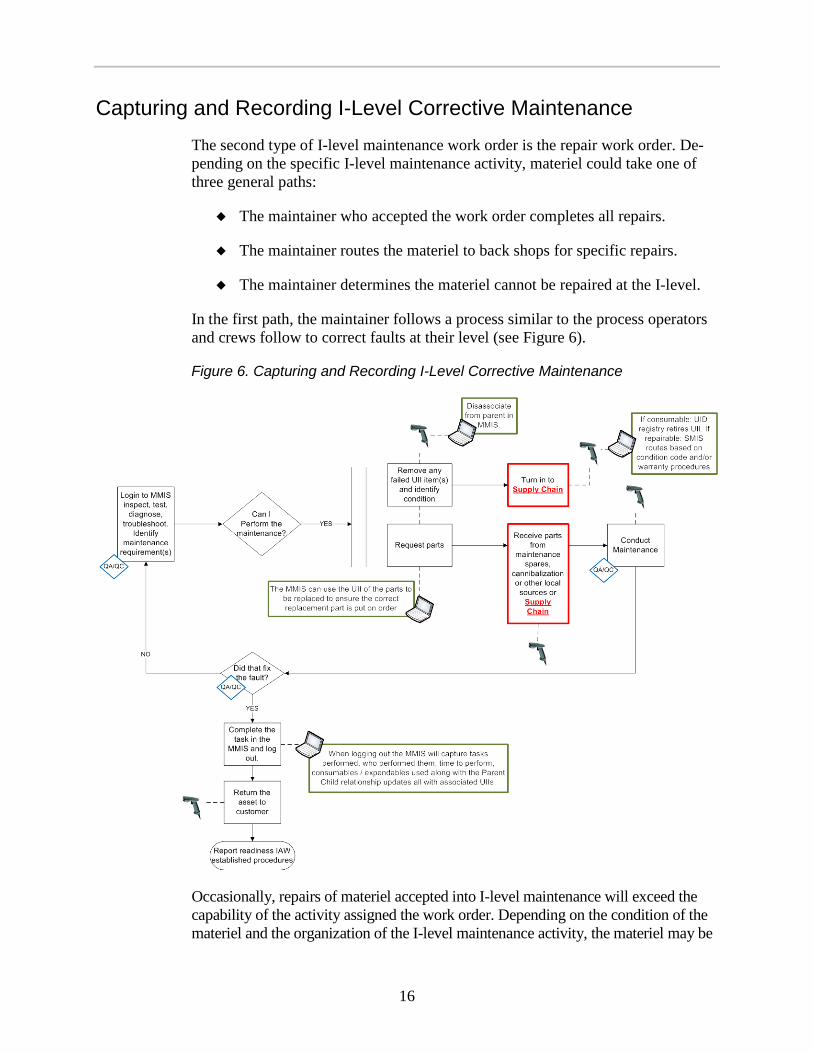
Capturing and Recording I-Level Corrective Maintenance The second type of I-level maintenance work order is the repair work order. De-pending on the specific I-level maintenance activity, materiel could take one of three general paths:
The maintainer who accepted the work order completes all repairs.
The maintainer routes the materiel to back shops for specific repairs.
The maintainer determines the materiel cannot be repaired at the I-level.
In the first path, the maintainer follows a process similar to the process operators and crews follow to correct faults at their level (see Figure 6).
Figure 6. Capturing and Recording I-Level Corrective Maintenance
Occasionally, repairs of materiel accepted into I-level maintenance will exceed the capability of the activity assigned the work order. Depending on the condition of the materiel and the organization of the I-level maintenance activity, the materiel may be

17
routed to a back shop for specific repairs, sent to the next higher level of mainten-ance, or determined to be not-repairable. Back shop maintainers follow the same re-pair process described above. When materiel is either sent to higher maintenance or deemed not-reparable, the maintainer assigns a materiel condition code and sends the materiel to supply for disposition. It is important the UII of the materiel be scanned when the asset is turned-in to supply to record the transfer of custody.
Figure 7 illustrates the process for routing materiel to back shops or a higher maintenance level.
Figure 7. Routing Materiel to Back Shops or Higher Maintenance
Capturing and Recording I-Level QA/QC and Safety Inspections
The final step in I-level maintenance is the QA/QC process and verification that all faults have been corrected. This process, which is identical to the O-level cap-ture and recording of QA/QC and safety inspections, is depicted in Figure 8.
Figure 8. Capturing and Recording I-Level QA/QC and Safety Inspections

18
I-Level IUID-Enabled SIM in Maintenance Process in Action
SCENARIO
The intermediate tail rotor gearbox that was discovered to be leaking during a routine O-level post-flight maintenance check of a helicopter arrives at I-level maintenance for repair.
IUID-ENABLED SIM PROCESS
At the I-level, the leaking gearbox from the O-level scenario is received and in-spected for condition and the proper documentation. Once the gearbox is received by I-level maintenance, it is inspected to determine its condition. The maintainer logs into MMIS using his CAC and scans the UII of the gearbox for proper docu-mentation. MMIS provides the work order information. Once the work order is ac-cepted, MMIS generates the necessary entries for the maintenance request register.
The gearbox is then sent to the appropriate back shop for repair. Once at the back shop, the maintainer assigned to the repair logs into MMIS, which confirms the maintainer is authorized to perform the repair. MMIS then provides all necessary instructions for the disassembly of the gearbox for faulty seal replacement. As the work progresses, MMIS captures each step of the process and captures the fault and fault-repair information that would otherwise be associated with an aircraft technical inspection worksheet and the related maintenance actions record.
As the work continues, the maintainer discovers that one of the gearbox bearings is rough. Replacement of this gearbox bearing is above I-level. The maintainer requests technical inspector verification through MMIS and the inspector verifies the fault. The maintainer reassembles the gearbox and scans the UII back into MMIS and en-ters “not repairable this station.” MMIS closes the work order, updates the informa-tion normally included on the aircraft component removal and repair/overhaul record, and prepares the necessary information for the unserviceable/repairable tag, which is attached to the gearbox. The technical inspector logs into the MMIS and signs the tag. The MMIS then closes the maintenance request register and advises the main-tainer to turn-in the gearbox to tech supply for a replacement.
Tech supply then log into the MMIS and scans the UII of the gearbox. MMIS provides tech supply the necessary shipping information for the appropriate depot overhaul facility.
All data concerning this gearbox to this point has been stored in the MMIS for depot use.

19
CURRENT PROCESS
At the-I level, the gearbox is received and inspected for condition and the proper documentation. It is then logged in for maintenance by completing a maintenance request register.
The gearbox is then sent to the appropriate back shop for repair, where an aircraft technical inspection worksheet is prepared and an initial inspection of the gearbox is performed. Faults are entered in this worksheet as the repair progresses. All re-lated maintenance actions are recorded on the related maintenance actions record, and any sub-component parts that are replaced are recorded on the maintenance request form.
As the gearbox is disassembled for replacement of the faulty seal, the mechanic notes that one of the gearbox bearings is rough. Replacement of this gearbox bearing assembly is a depot-level task. The gearbox must be returned to depot for repair.
At this point, the mechanic reassembles gearbox, updates the aircraft component removal and repair/overhaul record with the latest fault information, and com-pletes a new unserviceable/repairable tag. The unserviceable/repairable tag is signed by a technical inspector and attached to the gearbox.
A new gearbox is then ordered for the using unit, the maintenance request form is completed, and the maintenance request register is updated. The gearbox is turned into tech supply, which sends it to the depot for repair.
D-LEVEL IUID-ENABLED SIM The pinnacle of organic maintenance capability is inherent in the specialized skills and equipment found within the depots. The maintenance performed on ma-teriel at the depot is generally more comprehensive in both scope and composition than anywhere else in DoD’s organic maintenance structure. As such, the effect of maintenance on the attributes of items is greatest in the depot.
The IUID-enabled ability to capture, update, and record these actions in an auto-mated fashion brings the greatest improvements to the efficiency and effective-ness of depot maintenance.
Capturing and Recording the Induction of Items into Depot Maintenance
Items flow into depot maintenance according to a pre-planned master work sche-dule. As a specific item is inducted, an artisan scans its UII to record the accep-tance of the item into his or her custody. The artisan also launches electronic work

20
instructions automatically based on this scan. At this point, the artisan is mainly disassembling the item.
As IUID sub-assemblies, components, and modules are removed, the artisan scans their UIIs. This action disassociates the child sub-assembly, component, or mod-ule from its parent, thus automating the configuration update. These items are then routed to back shops.
The induction process is depicted in Figure 9.
Figure 9. Capturing and Recording the Induction of Items into Depot Maintenance
Capturing and Recording D-Level Maintenance in Back Shops
After being disassembled from the parent item, the subassemblies, components, and modules are routed to back shops to be repaired. When SIM items arrive at the back shops, they are scanned to record custody in the depot maintenance process. Once custody is established, a QA inspector inspects and tests all sub-assemblies and modules to diagnose or troubleshoot the fault and determine which of them should be repaired. The inspector scans the UII of SIM items, which confirms the inspection (inspector, location, date, and time) and allows for automated access to electronic technical data to aid in the repair decision.
Items that should not be repaired are turned-in to the supply system for disposal and the MMIS updates the IUID registry with the disposal action. Items that can be repaired are further disassembled according to work instructions that are pro-vided electronically to the artisan. Again, the UIIs of SIM items are scanned as they are removed from their parent. Once the individual piece parts of the sub-assemblies, components, and modules are ready to be inspected, the QA inspector scans the UIIs of any SIM items to confirm the inspection and accesses technical data to assess their condition and determine which should be disposed, reused, or repaired in the next steps of the process.

21
Figure 10 depicts this portion of the depot maintenance process.
Figure 10. Capturing and Recording D-Level Maintenance in Back Shops
Capturing and Recording D-Level Piece Part Maintenance and Sourcing
The next step in the depot maintenance process is to obtain parts that will be as-sembled into the final subassembly, component, or module that will be returned to the main line for final assembly into the end product. These parts can be obtained in one of three ways.
First, any item that cannot be repaired (that is, it cannot be returned to a serviceable condition) is turned-in to the supply chain for disposal and a replacement part is ordered and received through supply.
Second, the original item is reused, usually after it is, at a minimum, cleaned. SIM items must have their UII checked and reapplied as needed.
Third, the original item is remanufactured, fabricated, or modified. In some instances, the artisan might need additional parts to complete the modification or manufacture. If so, the artisan orders and receives these parts from the supply chain.
Whatever method is used to obtain replacement parts, it is important the custody of SIM items be tracked and recorded. This is accomplished through a scan of the

22
unique items’ UII as they enter and exit this portion of the depot maintenance process. In this fashion, the MMIS provides managers with real-time accurate da-ta about the custody of items throughout the process. Also, the MMIS can deliver maintenance instructions, parts information, and records maintenance actions at the point of maintenance.
This portion of the depot maintenance process is depicted in Figure 11.
Figure 11. Capturing and Recording D-Level Piece Part Maintenance and Sourcing
Capturing and Recording D-Level Maintenance Reassembly All the disassembled subassemblies, components, and modules are now ready for reassembly into their final form before being delivered to the main line for reassembly into the end product.
This portion of the process begins with the artisan scanning the UIIs of the unique items he or she is to reassemble. This updates the custody of the item in the MMIS. As the items are reassembled, additional scans are taken, as needed, to record the parent-child relationship (i.e., configuration) of the items as they are assembled. The MMIS provides the artisan with maintenance procedures, which are made available after each relevant UII scan.
After the item is reassembled, QA/QC inspects and tests the item, following procedures made available electronically after each relevant UII scan. The MMIS records the inspection took place at the item, which is confirmed by the scan. Items that pass the QA/QC inspection are either returned to stock or the assembly line. Items that fail inspection are re-inducted into the back shop.
The capture and recording of D-level reassembly is depicted in Figure 12. If the item is to be returned to stock, it is routed to supply as shown in Figure 13.

23
Figure 12. Capturing and Recording D-Level Reassembly
Final Assembly in Depot Maintenance The assembly line receives subassemblies, components, and modules either as new items, items from stock, or items that have gone through maintenance in back shops. As each unique item is received, the artisan scans its UII so the MMIS can maintain the custody record. After all items are received, the artisan begins reas-sembly, scanning UIIs as needed to record configuration in the MMIS. The final assembled items then are inspected.
The QA/QC inspector scans the UII which serves to record the location, date, and time of the inspection and provides automated access to electronic inspection and testing procedures. When items pass this inspection, they are ready for issue. Items that fail the inspection are re-inducted into the assembly line process.
This portion of the depot maintenance process, which ends with items being re-turned to stock in a ready-for-issue condition, is depicted in Figure 13.

24
Figure 13. Final Assembly and Quality Assurance in Depot Maintenance Process
Note: BOM = bill of materials; RFI = ready for issue.
D-Level IUID-Enabled SIM in Maintenance Process in Action
SCENARIO
The intermediate tail rotor gearbox that was found to be leaking during the O-level routine post flight maintenance check and was found to have a rough bearing at the I-level arrives at depot maintenance for repair.
IUID-ENABLED SIM PROCESS
The gearbox is received at the depot facility, where the UII is scanned. The MMIS opens a work order and completes the entries for the maintenance request register. The gearbox is routed to the back shop, where the maintainer logs into MMIS and scans the UII of the gearbox. The MMIS verifies the maintainer’s credentials and provides the maintainer with instructions on the proper disassembly, inspection, and repair procedures.
The MMIS initiates the data that would otherwise be associated with the aircraft technical inspection worksheet. The initial inspection is conducted, followed by various in-process inspections when QC call-outs are indicated. The MMIS noti-fies the technical inspector when to log in and complete the required inspection.
All repair actions associated with the overhaul are captured in the MMIS, as they would be with the related maintenance action record. All repair parts and the times associated with the replacement of components are similarly captured in the MMIS, which identifies for the maintainer any required technical upgrades.

25
After the gearbox is fully overhauled, and all inspections performed, the MMIS updates the database with the new information that previously would have been recorded on a new aircraft component removal and repair/overhaul record and modification work order. With information from scans and inputs from the main-tainer, the MMIS also completes the necessary information for the serviceable materiel tag, requests technical inspector signature, and instructs the maintainer to attach the tag to the serviceable gearbox.
The information applicable to the maintenance request form is updated in the MMIS, and the maintenance request register is closed, with instruction to turn the item into supply.
Once the gearbox is returned to supply, the supply technician scans its UII to veri-fy all documentation in the MMIS and places the gearbox in a ready-for-issue status. The gearbox is now available for delivery, when required.
CURRENT PROCESS
Once the gearbox is received at the depot maintenance facility, a maintenance re-quest form is completed and the gearbox is logged into the system using the main-tenance request register. The gearbox is then moved to the appropriate back shop for disassembly, cleaning, inspection, and repair.
The back shop technician initiates the process with an aircraft technical inspection worksheet, entering the nomenclature and serial number of the gearbox with the type of inspection—in this case overhaul. This is when the various inspection in-tervals are documented (i.e., initial, in-progress, and final). All repair actions as-sociated with the overhaul are documented on the related maintenance action record.
The gearbox is completely disassembled and all sub-components are cleaned. This is followed by an in-depth inspection of sub-components, with any unservi-ceable sub-components discarded. An initial inspection would likely be conducted at this point to verify sub-component serviceability.
Reassembly of the gearbox begins with in-progress inspections completed at critical assembly points. Any outstanding modification work orders are documented by completing an equipment modification record. Any serialized components that were replaced are recorded on the related maintenance action record. All component parts replaced are captured on the maintenance request form, along with hours it took to complete the maintenance.
Once the gearbox is fully assembled and all maintenance entries are completed, a fi-nal inspection is performed. A new aircraft component removal and repair/overhaul record is filled in, showing zero time since overhaul. That aircraft component remov-al and repair/overhaul record is packed with the gearbox. If a modification work order was completed, the equipment modification record is also included.

26
Finally, a serviceable materiel tag is completed, signed by a technical inspector, and attached to the gearbox. The serviceable materiel tag reflects the same data used to create the aircraft component removal and repair/overhaul record, in case the former is lost.
The maintenance request is then completed, the maintenance register is closed out, the maintenance records filed, and the gearbox is returned to supply in a ready-for-issue condition.
IUID DISCREPANCIES DISCOVERED DURING MAINTENANCE Maintenance may encounter incidents in which a item’s UII is damaged or miss-ing or the data from the UII does not match the data in a MMIS, and action must be taken.
When a maintainer encounters a serially managed item and scans or attempts to scan its UII, the MMIS should assist the maintainer in resolving any discrepan-cies. The desired outcomes are as follows:
No affect on maintenance turnaround time
No significant burden on the maintainer
The incident is resolved by the authorized military service activity
Items are suspended in the maintenance process only as absolutely neces-sary (e.g., safety critical)
No significant cost to maintenance or the customer.
Possible UII discrepancy solutions include the following:
Correct the discrepancy within the current maintenance cycle.
Note the discrepancy in the MMIS, indicating the serially managed item does not match, but continue to process it in maintenance.
The authorized military service activity resolves the identity issue and updates the MMIS, the UII, or both. The discovery of a damaged or incorrect UII could happen at any point in the maintenance process, whenever the UII is scanned. When a SIM item that arrives in maintenance has a damaged or incorrect UII, it is incumbent upon maintenance to
not use discrepant items if they are safety critical, controlled, or classi-fied, until the discrepancy is resolved;

27
correct the discrepancy within the current maintenance cycle, if reasonable; and
record and report the discrepancy (if not corrected) while continuing to process the item through the maintenance cycle.
In the discussion above, we identified where and how AIT can be used in the main-tenance process to improve its efficiency and effectiveness. Resolving discrepan-cies should not hinder the maintenance process when safety or other risks of using the discrepant item are not present. This basic rule is applicable regardless of the method used to track and report maintenance. In other words, an item that cannot be definitively identified would not be used if its use could negatively affect safety. The difference between the current manual process and IUID-enabled SIM is the latter leverages the power of automation to allow maintainers and maintenance managers to make better and faster decisions about resolving the use of discrepant materiel.
This section describes the general process that automation uses to resolve the dis-crepancy and inform the maintainer of what action to take.
There are at least five discrepancy modes that could be discovered during main-tenance operations. These five modes can be grouped into two categories: physi-cal mark errors and data errors. The following are among the physical mark errors that could be discovered in maintenance:
The MMIS indicates the item was previously marked, but no mark is evident.
There is a problem with the UII’s quality or condition (e.g., its location, adhesion, or a read error).
The item is supposed to have a UII (per technical data, Federal Logistics Information System, or service/agency plans), but the UII is not present.
The following are among data errors that could be discovered:
When the item’s UII is scanned, its data does not match MMIS data for that item.
An item received in maintenance is not what supply said it was going to send (e.g., wrong item or packaging and item UII do not match).
As SIM items are processed through maintenance (as described in the preceding sections), maintainers and artisans will scan the item’s UII at certain points in the maintenance process. It is at these points that the automated discrepancy resolu-tion process occurs. It is important to note that this resolution process is unnoticed by the maintainer unless the item must be suspended until the discrepancy is re-solved or if the maintainer needs to manually enter the item’s identification data.

28
Resolving Physical Mark Errors
During the maintenance process the maintainer is prompted to scan the SIM item’s UII. If the UII is not present or is damaged and cannot be scanned, the maintainer must determine if he or she can still use the item. If the item can be definitively identified using human-readable markings or another means and the correct UII can be determined, it might be feasible for the item to be marked or remarked within the current maintenance cycle, but only if it is within the authori-ty and capability of the maintenance activity to apply the mark.
But if the item cannot be definitively identified and it is a safety-critical, con-trolled, classified, or other type of item whose use would present risk, then the item should be suspended from use until the discrepancy is resolved. If using the item does not present risk, the discrepancy should be recorded and the item should continue through the maintenance process. This resolution process is depicted in Figure 14.
Figure 14. Resolving Physical Marking Errors
Resolving Data Errors
When the SIM item’s UII is present and can be scanned, the MMIS will compare the scanned data to expected data. Expected data comes from a number of sources, including the known configuration of the item, the service or agency’s IUID repository, the DoD IUID Registry, or advance ship notices from supply.

29
If the data matches, maintenance continues. If the data does not match then the UII is incorrect or the MMIS is incorrect or both. If the MMIS is correct, but the UII is not, then the resolution is to correct the mark which is the same process re-quired to resolve physical mark errors described above. If the MMIS data is not correct, and the maintenance activity has the authority to correct it, then it should correct it and proceed with maintenance. If the maintenance activity does not have the authority to correct the MMIS data, it should submit a corrective change re-quest and proceed with maintenance, as long as using the item does not present risk. If both the UII and the MMIS data are incorrect, then both resolutions must be pursued.
The process for data error resolution is depicted in Figure 15.

31
Figure 15. Resolving Data Errors
A-1
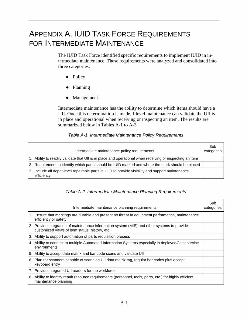
APPENDIX A. IUID TASK FORCE REQUIREMENTS FOR INTERMEDIATE MAINTENANCE
The IUID Task Force identified specific requirements to implement IUID in in-termediate maintenance. These requirements were analyzed and consolidated into three categories:
Policy
Planning
Management.
Intermediate maintenance has the ability to determine which items should have a UII. Once this determination is made, I-level maintenance can validate the UII is in place and operational when receiving or inspecting an item. The results are summarized below in Tables A-1 to A-3.
Table A-1. Intermediate Maintenance Policy Requirements
Intermediate maintenance policy requirements Sub
categories
1. Ability to readily validate that UII is in place and operational when receiving or inspecting an item 2. Requirement to identify which parts should be IUID marked and where the mark should be placed 3. Include all depot-level repairable parts in IUID to provide visibility and support maintenance
efficiency
Table A-2. Intermediate Maintenance Planning Requirements
Intermediate maintenance planning requirements Sub
categories
1. Ensure that markings are durable and present no threat to equipment performance, maintenance efficiency or safety
2. Provide integration of maintenance information system (MIS) and other systems to provide customized views of item status, history, etc.
3. Ability to support automation of parts requisition process 4. Ability to connect to multiple Automated Information Systems especially in deployed/Joint service
environments
5. Ability to accept data matrix and bar code scans and validate UII 6. Plan for scanners capable of scanning UII data matrix tag, regular bar codes plus accept
keyboard entry
7. Provide integrated UII readers for the workforce 8. Ability to identify repair resource requirements (personnel, tools, parts, etc.) for highly efficient
maintenance planning

A-2
Table A-3. Intermediate Maintenance Management Requirements
Intermediate maintenance management requirements Sub categories
1. Ability to track item location, custody, and status through the field maintenance process
Capture and store UII locally for uses as may be required
Maintain strict accountability within storage and maintenance facilities by UII for most intensively ma-naged items
Provide visibility of item location, condition, status, history, etc.
2. Ability to record item configuration changes by UII in system of record
3. Ability to validate the mark is in place and operational If mark is not in place/operational, take discrepancy actions in accordance with military service instructions
4. Ability to capture positive item identification Including two-person signoff on custody transfer as necessary
5. Perform unit level inventory using UII Receiver at field maintenance (FM) activity will col-lect UII via AIT and update the accountability record
6. Ability to capture part configuration, status, and usage data sufficient to support determination of military equipment valuation and useful life
7. Ability to easily enter accurate data generated in FM operations
8. Ability to retrieve essential maintenance information at the point of maintenance
9. For end item UII not marked, take appropriate steps to create record in IUID registry in accordance with service instructions
10. Ability to support precision maintenance and perfor-mance management with history and technical information
Configuration, status, and installation—to positively identify the item, link it to the higher assembly, and identify the correct repair parts
Discrepancy, sensor, and diagnostic information linked to UII to support rapid and accurate diagnosis including prognostics
Link technical data, interactive electronic technical manuals, directives, and repair authorizations for accurate and precise repair capability and decisions
11. Ability to identify warranty condition and disposition items accordingly
12. Ability to automatically provide repair requirements (technical directives, time changes/time-based actions, etc.)
13. Ability to support reliability analysis (Bad actors, relia-bility centered maintenance [RCM], condition based maintenance plus [CBM+], etc.) with maintenance history tracking from across the logistics enterprise

B-1
APPENDIX B. IUID TASK FORCE REQUIREMENTS FOR DEPOT MAINTENANCE
The IUID Task Force also identified specific requirements for implementing IUID in depot maintenance. These requirements were analyzed and consolidated into three separate categories:
Policy
Planning
Management.
The results are summarized in Tables B-1 through B-3.
Table B-1. Depot Maintenance Policy Requirements
Depot maintenance policy requirements Sub categories
1. Identify Marking Requirements 2. Assign UII Must be done prior to induction/receipt and attach to
travelers/tags 3. Establish and execute QA requirements per military
standards Mark items per Military-Standard (MIL-STD-130) (e.g. tech data, work scope)
Mark packaging per MIL-STD-129 and work scope Mark depot maintenance (DM) capital equipment/
tooling per Department of Defense Instruction 8320.04 Mark government furnished property (GFP)
per MIL-STD-130 Mark per service/agency-unique marking require-
ments, implementation strategies, and plans 4. Common Automated Identification Technology tools
to read markings and connect to Automated Infor-mation Systems
Table B-2. Depot Maintenance Planning Requirements
Depot maintenance planning requirements Sub categories
1. Plan marking requirements in normal work scope 2. Establish depot maintenance capability to mark
parts and packaging for applicable items in the depot repair cycle
3. Define depot maintenance work requirements Based upon optimal repair processes, using UII (precision maintenance)
Apply shop findings to adjust work requirements and build standards
Provide inputs to future workload planning

B-2
Table B-2. Depot Maintenance Planning Requirements
Depot maintenance planning requirements Sub categories
4. Automate recording of disposable/demilitarized actions to applicable system of record
5. Verification of marking prior to shipment Verify pack and item marking match prior to issue.
Table B-3. Depot Maintenance Management Requirements
Depot maintenance management requirements Sub categories
1. Repair/replace lost or damaged marks 2. Access life cycle history information of inbound
items prior to receipt Tailor work requirement and align necessary resources Perform warranty management by UII
Scope special handling (matched assemblies, foreign military sales, bad actor, etc.) via UII
Provide access to DM maintenance actions and find-ings for analysis (RCM, CBM+, RAM, bad actor, no fault found, etc.)
Provide repair cost and cycle time history to support total ownership cost reduction, readiness optimization, and business process reengineering
3. Acknowledge inbound receipt of physical assets via UII (if available)
4. Track item identification, location, status, find-ings/actions taken via UII through repair cycle
Support work-in-process inventory and disposal/ demilitarization
Enable process and PLM analysis including repair cycle time/turn- around time
Verify inbound receipt and outbound issue of UII items 5. Track depot maintenance capital equipment usage
and condition by UII
6. Close out depot maintenance tracking at hand-off to next node (receipt verification)
7. Capture/store UII information per service/agency requirements
RCM, CBM+, total ownership cost reduction, warranty management, configuration management, safety, etc.
8. Maintain positive inventory control through repair cycle by UII
9. Track fabricated/modified items and incorporation of GFP by UII
10. Document demilitarization/disposal actions by UII Query UII to identify previously disposed/demilitarized assets
11. Link item UII to life cycle management data by service/agency-specific identification mechanism
12. Facilitate connectivity via UII related databases Single key to echelons, enterprise, partners, Services, agencies, etc.

B-3
Table B-3. Depot Maintenance Management Requirements
Depot maintenance management requirements Sub categories
13. Tailor work requirement and align necessary resources
Conduct pre-induction supportability analysis
14. Manage maintenance repair and overhaul work flow including induction, location delays
Remove individual bad actors from the repair cycle Link personnel to work performed to identify training and other requirements
Streamline management of life-limited and matched assembly parts
Maximize depot maintenance capital equipment/tooling capacity uptime
Automate production reporting, expedite financial transactions
Conduct cost, schedule, and quality analysis 15. Report/document depot maintenance assets by UII
(work in progress, capital equipment, tooling, etc.) supporting IIM/primary inventory control point, property book, and recall
16. Use UII to improve forecast requirements, asset management for spares, and resources output projections
17. Generate updated configuration management in-formation to support project manager’s modification programs
18. Support valuation and accountability functions by capturing modifications, fabrication/manufacture, service life extension, GFP incorporation, and disposal actions by UII
19. Apply UII to support quality deficiency report/ malfunction defect report/warrant programs
20. Interrogate UII registry, related systems of record 21. Use UII as key link for integrated access to multiple
MIS and other systems to provide customized views of item status, history
Production management and quality assurance systems Usage and repair history systems Maintenance management information systems
Property and accountability systems Configuration management systems Supply and distribution information systems Disposal systems

C-1
APPENDIX C. PROCESS MAPS LEGEND Table C-1 describes the symbols, shapes, and marks that appear in each process map.
Table C-1. Process Map Descriptions
Shape, symbol, or mark Description Definition
Solid black line with an ar-row at one or both ends
Depicts the physical flow of SIM items through the process.
Dashed black line without arrows
Depicts a bidirectional flow of data.
Oval Represents the beginning and end of the process.
Diamond Represents a decision point in the process. Departing depends on the answer to the ques-tion stated within it. The answer will be yes or no. This leads to the next step in the process indicated by the appropriate arrow.
Rectangle Represents a predefined process.
Parallel lines (horizontal or vertical)
Represents a parallel process.
Text box with a green border
Represents an automated process.
Text box with a red border Represents a handoff or transition point from the specific maintenance process to another maintenance process or supply.
Circle with a brown border Represents a point in the process where a SIM item is scanned. It always numbered to indicate why the scan is needed. It is always accompanied by a lettered circle with a green border to indicate that the AIS must verify and validate the scan.
Circle with a green border Represents a defined automated process.

C-2
Table C-1. Process Map Descriptions
Shape, symbol, or mark Description Definition
Circle with a brown border and the number one
Change of Custody Scan. The MMIS notifies the maintainer that the item has a UII and to scan it to confirm the process and associate the individual to the work being performed.
Circle with a brown border and the number two
Inspection/Safety Scan. The MMIS notifies the maintainer that the item has a UII and to scan it to associate the inspector to the asset and confirm inspector was at the asset (location, date, and time).
Circle with a brown border and the number three
Serialized Configuration Scan. The MMIS noti-fies the maintainer that the item has a UII and to scan it when it is removed or installed.
Circle with a green border and the letter A
The MMIS verifies and validates UII. The MMIS compares the UII data to recorded data. If discrepancies are found, the MMIS will pro-vide discrepancy resolution instructions.
Circle with a green border and the letter B
Represents the automated process that takes place when the user, maintainer, or artisan logs into the MMIS; associates the individual to the specific asset and checks their certification.
Circle with a green border and the letter C
The MMIS provides tech data (e.g., instruc-tions, tools required) based on the configura-tion of the items in maintenance.
Diamond with a blue border and the letters QA/QC
Refers to the QA/QC subroutine when QA/QC is required or requested.
Image of a scanner Represents the points in the process where AIT is used to capture the unique identity of a SIM item.
Image of a laptop Represents the MMIS and the interface be-tween the maintainer and the AIT. Indicates where automation is used to enable the process.

D-1
APPENDIX D. IUID-ENABLED SIM IN MAINTENANCE PROCESS MAPS
The IUID-Enabled Serialized Item Management in Operations and Maintenance discussion provided a description of how maintenance actions would be captured and reported utilizing the tenets of IUID serialized item management. It focused on preventive and corrective maintenance at the organizational and intermediate levels, to include quality control, and described how depot maintenance actions would be accomplished. Discrepancy resolution was also discussed. Each discus-sion was followed by a figure graphically briefly depicting the process flow.
Figures D-1, D-2, and D-3 show the O-level, I-level, and D-level processes in their entirety.

D-3
Figure D-1. IUID-Enabled SIM in Operator/Crew/Organizational Maintenance Process

D-5
Figure D-2. IUID-Enabled SIM in Intermediate Maintenance Process

D-7
Figure D-3. IUID-Enabled SIM in Depot Maintenance Process

E-1
APPENDIX E. ABBREVIATIONS AIT/AIS automated information technology and systems
CAC common access card
CBM+ condition based maintenance plus
DM depot maintenance
DODI DoD Instruction
FM Field Maintenance
GFP Government Furnished Property
IIM intensive item management
IUID Item Unique Identification
MIL-STD military standard
MIS maintenance information system
MMIS maintenance management information system
PA property accountability
PLM product lifecycle management
PMCS preventive maintenance checks and services
QA/QC quality assurance or quality control RAM reliability, availability, and maintainability
RCM reliability-centered maintenance
SIM serialized item management
UII unique item identification

IUID-Enabled Serialized Item Management in Operations and Maintenance
Logistics IUID Task Force
November 2011