itu-t g.681
TRANSCRIPT
8/10/2019 ITU-T G.681
http://slidepdf.com/reader/full/itu-t-g681 1/39
INTERNATIONAL TELECOMMUNICATION UNION
TELECOMMUNICATIONSTANDARDIZATION SECTOROF ITU
(10/96)
SERIES G: TRANSMISSION SYSTEMS AND MEDIA,DIGITAL SYSTEMS AND NETWORKSTransmission media characteristics – Characteristics ofoptical components and sub-systems
ITU-T Recommendation G.681(Previously CCITT Recommendation)

8/10/2019 ITU-T G.681
http://slidepdf.com/reader/full/itu-t-g681 2/39
ITU-T G-SERIES RECOMMENDATIONS
For further details, please refer to ITU-T List of Recommendations.
INTERNATIONAL TELEPHONE CONNECTIONS AND CIRCUITS G.100–G.199
GENERAL CHARACTERISTICS COMMON TO ALL ANALOGUE CARRIER-TRANSMISSION SYSTEMS
G.200–G.299
INDIVIDUAL CHARACTERISTICS OF INTERNATIONAL CARRIER TELEPHONESYSTEMS ON METALLIC LINES
G.300–G.399
GENERAL CHARACTERISTICS OF INTERNATIONAL CARRIER TELEPHONESYSTEMS ON RADIO-RELAY OR SATELLITE LINKS AND INTERCONNECTIONWITH METALLIC LINES
G.400–G.449
COORDINATION OF RADIOTELEPHONY AND LINE TELEPHONY G.450–G.499
General G.600–G.609
Symmetric cable pairs G.610–G.619Land coaxial cable pairs G.620–G.629Submarine cables G.630–G.649Optical fibre cables G.650–G.659
TERMINAL EQUIPMENTS G.700–G.799DIGITAL NETWORKS G.800–G.899DIGITAL SECTIONS AND DIGITAL LINE SYSTEM G.900–G.999

8/10/2019 ITU-T G.681
http://slidepdf.com/reader/full/itu-t-g681 3/39
ITU-T RECOMMENDATION G.681
FUNCTIONAL CHARACTERISTICS OF INTEROFFICE AND LONG-HAULLINE SYSTEMS USING OPTICAL AMPLIFIERS, INCLUDING
OPTICAL MULTIPLEXING
Summary
This Recommendation covers the functional characteristics of interoffice and long-haul line systemsusing optical amplifiers, including optical multiplexing. It represents a bridge between
reference/physical configurations of SDH interoffice systems described in Recommendations G.782,G.783, G.958 and between functional transport network architectures described in RecommendationsG.803 and G.805. Extended or new "functional blocks, functions and sub-functions" of SDHequipment (e.g. line termination, optical/electrical/optical regenerator and optical non-regenerativerepeater) are mapped on "compound functions, atomic functions and processes" of transportnetworks. Optical channel layer, optical multiplex section layer and optical amplifier section layerare identified for optical transport systems. In addition optical safety considerations, includingAutomatic Power Shutdown (APSD) and Optical Surge Prevention (OSP), and the OpticalSupervisory Channel (OSC) are topics of this Recommendation.
In future Recommendations on "optical media-based transport network architectures", there will be
standardized "optical path layer with optical add and drop multiplexers and optical cross-connects"and "optical circuit layer with optical switches" which are not in the scope of this Recommendation.
Source
ITU-T Recommendation G.681 was prepared by ITU-T Study Group 15 (1993-1996) and wasapproved by WTSC (Geneva, 9-18 October 1996).
8/10/2019 ITU-T G.681
http://slidepdf.com/reader/full/itu-t-g681 4/39
ii Recommendation G.681 (10/96)
FOREWORD
ITU (International Telecommunication Union) is the United Nations Specialized Agency in the field of telecommunications. The ITU Telecommunication Standardization Sector (ITU-T) is a permanent organ of the ITU. The ITU-T is responsible for studying technical, operating and tariff questions and issuing
Recommendations on them with a view to standardizing telecommunications on a worldwide basis.The World Telecommunication Standardization Conference (WTSC), which meets every four years,establishes the topics for study by the ITU-T Study Groups which, in their turn, produce Recommendationson these topics.
The approval of Recommendations by the Members of the ITU-T is covered by the procedure laid down inWTSC Resolution No. 1.
In some areas of information technology which fall within ITU-T’s purview, the necessary standards areprepared on a collaborative basis with ISO and IEC.
NOTE
In this Recommendation, the expression "Administration" is used for conciseness to indicate both atelecommunication administration and a recognized operating agency.
INTELLECTUAL PROPERTY RIGHTS
The ITU draws attention to the possibility that the practice or implementation of this Recommendation mayinvolve the use of a claimed Intellectual Property Right. The ITU takes no position concerning the evidence,validity or applicability of claimed Intellectual Property Rights, whether asserted by ITU members or othersoutside of the Recommendation development process.
As of the date of approval of this Recommendation, the ITU had/had not received notice of intellectualproperty, protected by patents, which may be required to implement this Recommendation. However,implementors are cautioned that this may not represent the latest information and are therefore strongly urgedto consult the TSB patent database.
ITU 1997
All rights reserved. No part of this publication may be reproduced or utilized in any form or by any means,electronic or mechanical, including photocopying and microfilm, without permission in writing from the ITU.
8/10/2019 ITU-T G.681
http://slidepdf.com/reader/full/itu-t-g681 5/39
Recommendation G.681 (10/96) iii
CONTENTS
Page
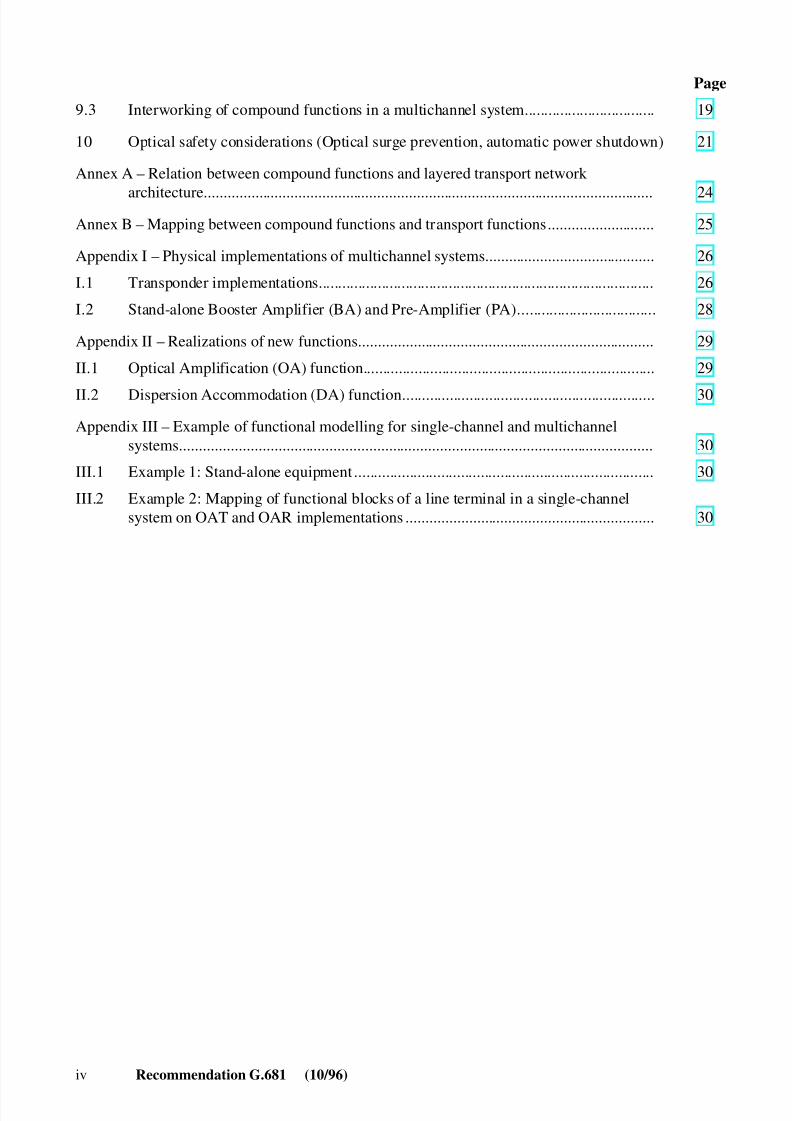
1 Scope........................................................................................................................... 1
2 References................................................................................................................... 1
3 Terms and definitions ................................................................................................. 2
3.1 Definitions .................................................................................................................. 3
3.2 Terms defined in other Recommendations ................................................................. 3
4 Abbreviations.............................................................................................................. 3
5 Applications................................................................................................................ 6
5.1 System types ............................................................................................................... 6
5.2 System components .................................................................................................... 7
6 Types of transmission medium................................................................................... 7
7 Definitions of functions and compound functions (Functional blocks)...................... 7
7.1 Functions defined in other Recommendations............................................................ 7
7.2 New functions and compound functions (Functional blocks) .................................... 7
7.2.1 Optical Channel Adaptation and Termination (OCA/OCT) compoundfunction.......................................................................................................... 8
7.2.2 Optical Supervisory Channel Adaptation/Optical Channel Termination(OSCA/OCT) compound function................................................................. 10
7.2.3 Optical Multiplex Section Adaptation and Termination (OMSA/OMST)compound function ........................................................................................ 10
7.2.4 Optical Amplifier Section Adaptation and Termination (OASA/OAST)compound function ........................................................................................ 11
7.2.5 Other functions/processes for internetworking.............................................. 13
8 Reference configurations for single-channel systems................................................. 14
8.1 Compound functions describing single-channel systems ........................................... 14
8.2 Functional configuration for single-channel interoffice line (IOL) systems............... 14
8.2.1 Without in-line function capabilities ............................................................. 14
8.2.2 In-line non-regenerative repeater................................................................... 14
8.2.3 Regenerator.................................................................................................... 15
9 Reference configurations for multichannel systems................................................... 17
9.1 Functional blocks describing multichannel systems................................................... 17
9.2 Functional configurations for a multichannel interoffice line system ........................ 17
9.2.1 Without in-line function capabilities ............................................................. 17
9.2.2 Non-regenerative repeater.............................................................................. 189.2.3 Regenerator.................................................................................................... 18
8/10/2019 ITU-T G.681
http://slidepdf.com/reader/full/itu-t-g681 6/39
iv Recommendation G.681 (10/96)
Page
9.3 Interworking of compound functions in a multichannel system................................. 19
10 Optical safety considerations (Optical surge prevention, automatic power shutdown) 21
Annex A – Relation between compound functions and layered transport network
architecture.................................................................................................................. 24Annex B – Mapping between compound functions and transport functions........................... 25
Appendix I – Physical implementations of multichannel systems........................................... 26
I.1 Transponder implementations..................................................................................... 26
I.2 Stand-alone Booster Amplifier (BA) and Pre-Amplifier (PA)................................... 28
Appendix II – Realizations of new functions........................................................................... 29
II.1 Optical Amplification (OA) function.......................................................................... 29
II.2 Dispersion Accommodation (DA) function................................................................ 30
Appendix III – Example of functional modelling for single-channel and multichannelsystems........................................................................................................................ 30
III.1 Example 1: Stand-alone equipment ............................................................................ 30
III.2 Example 2: Mapping of functional blocks of a line terminal in a single-channelsystem on OAT and OAR implementations ............................................................... 30
8/10/2019 ITU-T G.681
http://slidepdf.com/reader/full/itu-t-g681 7/39
Recommendation G.681 (10/96) 1
Recommendation G.681
FUNCTIONAL CHARACTERISTICS OF INTEROFFICE AND LONG-HAULLINE SYSTEMS USING OPTICAL AMPLIFIERS, INCLUDING
OPTICAL MULTIPLEXING
(Geneva 1996)
1 Scope
This Recommendation applies to the functional characteristics of interoffice and long-haul linesystems using Optical Amplifiers (OAs), including optical multiplexing. Existing Recommendationssuch as G.958, and the G.780-Series have not considered these new technologies. As such thisRecommendation is the first attempt to characterize the functions that OAs and optical multiplexingrequire to describe these capabilities. Its present structure and contents describe the systems whereoptical interfaces for single-channel systems with optical amplifiers and optical interfaces formultichannel systems with optical amplifiers are implemented.
This Recommendation represents a bridge between reference/physical configurations of SDHinteroffice systems in Recommendations G.782, G.783, G.958 and between functional network architectures described in Recommendations G.803 and G.805. Thus, it is structured in a way that isintended to complement the directions that the network architecture and the network managementactivities are following. The guiding principles of these areas have been used in developing thisdescription. The description is based on a client/server approach. In order to provide this, thefunctional blocks described in this Recommendation were derived from rules developed from layeredtransport architecture techniques. The functions related to management were developed from anunderstanding of information flows. It is not in the scope of this Recommendation to identify howthe management messages are formatted or the protocols by which they are conveyed.
The line systems described within this Recommendation are intended to provide transversecompatibility, i.e. the possibility of mixing various manufacturers’ equipments within a particularsystem. The use of optical transmission capabilities including optical multiplexing and amplificationrequires management solutions.
This Recommendation describes how a supervisory signal is combined with user information.
NOTE – This Recommendation has been prepared from the experience with Erbium-doped silica-based fibreamplifiers (EDFA), operating in the 1550 nm wavelength region. Future optical amplifiers (e.g. semi-conductor optical amplifiers or optical amplifiers based on different active fibres, possibly in the 1310 nm
wavelength region) are not intended to be excluded from this Recommendation and may lead to additionalfunctions, as well as to modifications of the existing ones.
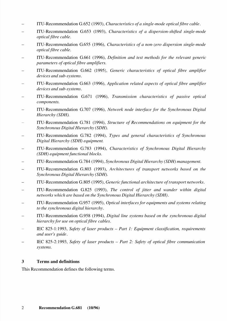
2 References
The following ITU-T Recommendations and other references contain provisions which, throughreference in this text, constitute provisions of this Recommendation. At the time of publication, theeditions indicated were valid. All Recommendations and other references are subject to revision; allusers of this Recommendation are therefore encouraged to investigate the possibility of applying themost recent edition of the Recommendations and other references listed below. A list of the currentlyvalid ITU-T Recommendations is regularly published.
8/10/2019 ITU-T G.681
http://slidepdf.com/reader/full/itu-t-g681 8/39
2 Recommendation G.681 (10/96)
– ITU-Recommendation G.652 (1993), Characteristics of a single-mode optical fibre cable .
– ITU-Recommendation G.653 (1993), Characteristics of a dispersion-shifted single-modeoptical fibre cable .
– ITU-Recommendation G.655 (1996), Characteristics of a non-zero dispersion single-modeoptical fibre cable .
– ITU-Recommendation G.661 (1996), Definition and test methods for the relevant generic parameters of optical fibre amplifiers .
– ITU-Recommendation G.662 (1995), Generic characteristics of optical fibre amplifier devices and sub-systems .
– ITU-Recommendation G.663 (1996), Application related aspects of optical fibre amplifier devices and sub-systems .
– ITU-Recommendation G.671 (1996), Transmission characteristics of passive opticalcomponents .
– ITU-Recommendation G.707 (1996), Network node interface for the Synchronous Digital Hierarchy (SDH) .
– ITU-Recommendation G.781 (1994), Structure of Recommendations on equipment for theSynchronous Digital Hierarchy (SDH) .
– ITU-Recommendation G.782 (1994), Types and general characteristics of Synchronous Digital Hierarchy (SDH) equipment .
– ITU-Recommendation G.783 (1994), Characteristics of Synchronous Digital Hierarchy(SDH) equipment functional blocks .
– ITU-Recommendation G.784 (1994), Synchronous Digital Hierarchy (SDH) management .
– ITU-Recommendation G.803 (1993), Architectures of transport networks based on theSynchronous Digital Hierarchy (SDH) .
– ITU-Recommendation G.805 (1995), Generic functional architecture of transport networks .
– ITU-Recommendation G.825 (1993), The control of jitter and wander within digitalnetworks which are based on the Synchronous Digital Hierarchy (SDH) .
– ITU-Recommendation G.957 (1995), Optical interfaces for equipments and systems relatingto the synchronous digital hierarchy .
– ITU-Recommendation G.958 (1994), Digital line systems based on the synchronous digitalhierarchy for use on optical fibre cables .
– IEC 825-1:1993, Safety of laser products – Part 1: Equipment classification, requirementsand user's guide .
– IEC 825-2:1993, Safety of laser products – Part 2: Safety of optical fibre communicationsystems .
3 Terms and definitions
This Recommendation defines the following terms.

8/10/2019 ITU-T G.681
http://slidepdf.com/reader/full/itu-t-g681 9/39
Recommendation G.681 (10/96) 3
3.1 Definitions
3.1.1 optical amplifier : The optical amplifier is an element that alters the amplitude of theincident signals but does not perform timing recovery or decision thresholding. Many optical signalscan be accommodated simultaneously. It can communicate to the system management facility using adata messaging channel, which may be of optical and electrical means. The optical supervisory signalis for monitoring in-line optical amplifiers. The electrical supervisory signal approach is used insystems without in-line amplifiers.
3.1.2 wavelength : Whilst wavelength is used throughout this Recommendation, it is recognizedthat future multichannel systems will be defined in frequency spacing. Wavelength and frequency areinterchangeable for the purposes of this Recommendation.
3.1.3 optical channel : The optical channel in an optical interoffice link or regenerator sectionstarts at the access point, AP, of an OCA/OCT in a line termination (or regenerator) and ends at theaccess point, AP, of an OCA/OCT in a line termination (or regenerator).
3.1.4 compound function : The compound function contains a number of atomic functions in asingle layer.
3.1.5 atomic function : The atomic function is a function, which, if divided into simpler functionswould no longer be uniquely defined for transmission hierarchies. It is therefore indivisible from anetwork point of view. Atomic functions are composed of a number of processes. The atomicfunctions associated with each layer are the trail termination function and adaptation function.
3.1.6 process : A process is a generic term for an action or collection of actions. A process receivesinput messages in defined format, processes the inputs in a defined way, and generates outputmessages in defined format.
3.2 Terms defined in other Recommendations
– optical/electrical/optical regenerator (REG): see Recommendation G.958;– Optical Amplifier (OA): see Recommendations G.661, G.662 and G.663;
– optical multiplexer/demultiplexer: see Recommendation G.671;
– regenerator section overhead (RSOH): see Recommendation G.782;
– regenerator section termination (RST): see Recommendation G.782;
– S/R reference points: see Recommendations G.955 and G.957;
– A, ..., L reference points: see Recommendations G.955 and G.957;
– SDH physical interface (SPI): see Recommendations G.782, G.783 and G.958;
– section overhead (SOH): see Recommendation G.707;– Synchronous Digital Hierarchy (SDH): see Recommendation G.707;
– Synchronous Equipment Management Function (SEMF): see Recommendation G.782;
– Synchronous Transport Module (STM): see Recommendation G.707.
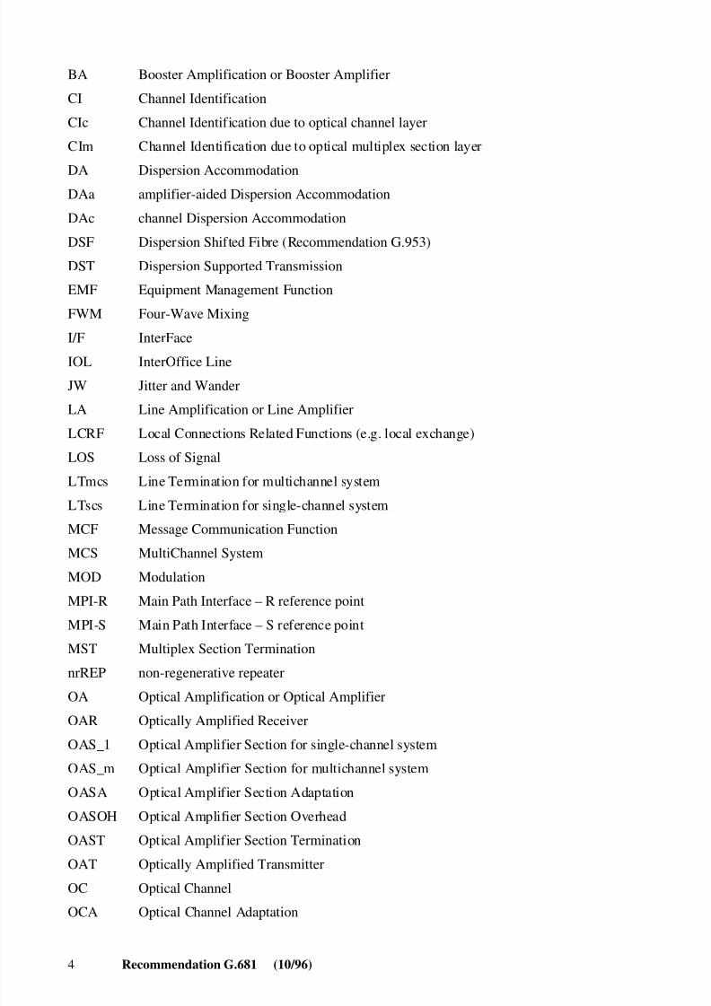
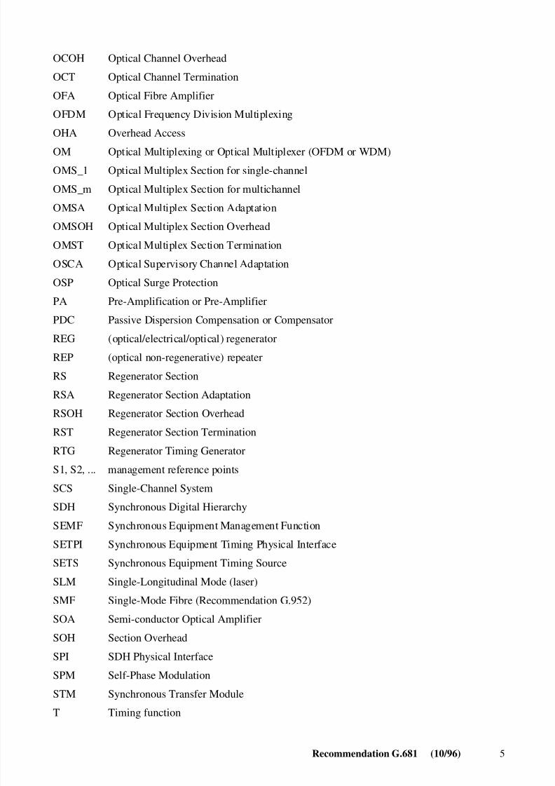
4 Abbreviations
This Recommendation uses the following abbreviations.
ALS Automatic Laser Shutdown
AP Access PointAPSD Automatic Power Shutdown
8/10/2019 ITU-T G.681
http://slidepdf.com/reader/full/itu-t-g681 10/39
4 Recommendation G.681 (10/96)
BA Booster Amplification or Booster Amplifier
CI Channel Identification
CIc Channel Identification due to optical channel layer
CIm Channel Identification due to optical multiplex section layer
DA Dispersion AccommodationDAa amplifier-aided Dispersion Accommodation
DAc channel Dispersion Accommodation
DSF Dispersion Shifted Fibre (Recommendation G.953)
DST Dispersion Supported Transmission
EMF Equipment Management Function
FWM Four-Wave Mixing
I/F InterFace
IOL InterOffice Line
JW Jitter and Wander
LA Line Amplification or Line Amplifier
LCRF Local Connections Related Functions (e.g. local exchange)
LOS Loss of Signal
LTmcs Line Termination for multichannel system
LTscs Line Termination for single-channel system
MCF Message Communication FunctionMCS MultiChannel System
MOD Modulation
MPI-R Main Path Interface – R reference point
MPI-S Main Path Interface – S reference point
MST Multiplex Section Termination
nrREP non-regenerative repeater
OA Optical Amplification or Optical Amplifier
OAR Optically Amplified Receiver
OAS_1 Optical Amplifier Section for single-channel system
OAS_m Optical Amplifier Section for multichannel system
OASA Optical Amplifier Section Adaptation
OASOH Optical Amplifier Section Overhead
OAST Optical Amplifier Section Termination
OAT Optically Amplified Transmitter
OC Optical Channel
OCA Optical Channel Adaptation
8/10/2019 ITU-T G.681
http://slidepdf.com/reader/full/itu-t-g681 11/39
Recommendation G.681 (10/96) 5
OCOH Optical Channel Overhead
OCT Optical Channel Termination
OFA Optical Fibre Amplifier
OFDM Optical Frequency Division Multiplexing
OHA Overhead AccessOM Optical Multiplexing or Optical Multiplexer (OFDM or WDM)
OMS_1 Optical Multiplex Section for single-channel
OMS_m Optical Multiplex Section for multichannel
OMSA Optical Multiplex Section Adaptation
OMSOH Optical Multiplex Section Overhead
OMST Optical Multiplex Section Termination
OSCA Optical Supervisory Channel Adaptation
OSP Optical Surge Protection
PA Pre-Amplification or Pre-Amplifier
PDC Passive Dispersion Compensation or Compensator
REG (optical/electrical/optical) regenerator
REP (optical non-regenerative) repeater
RS Regenerator Section
RSA Regenerator Section Adaptation
RSOH Regenerator Section OverheadRST Regenerator Section Termination
RTG Regenerator Timing Generator
S1, S2, ... management reference points
SCS Single-Channel System
SDH Synchronous Digital Hierarchy
SEMF Synchronous Equipment Management Function
SETPI Synchronous Equipment Timing Physical Interface
SETS Synchronous Equipment Timing Source
SLM Single-Longitudinal Mode (laser)
SMF Single-Mode Fibre (Recommendation G.952)
SOA Semi-conductor Optical Amplifier
SOH Section Overhead
SPI SDH Physical Interface
SPM Self-Phase Modulation
STM Synchronous Transfer Module
T Timing function
8/10/2019 ITU-T G.681
http://slidepdf.com/reader/full/itu-t-g681 12/39
6 Recommendation G.681 (10/96)
TCRF Transit Connections Related Functions (e.g. transit exchange)
WA Wavelength Assignment
WC Wavelength (frequency) Conversion
WDM Wavelength Division Multiplexing
Wref Wavelength referencing
5 Applications
5.1 System types
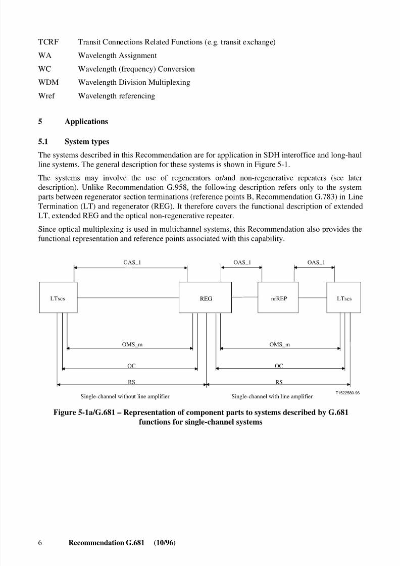
The systems described in this Recommendation are for application in SDH interoffice and long-haulline systems. The general description for these systems is shown in Figure 5-1.
The systems may involve the use of regenerators or/and non-regenerative repeaters (see laterdescription). Unlike Recommendation G.958, the following description refers only to the system
parts between regenerator section terminations (reference points B, Recommendation G.783) in LineTermination (LT) and regenerator (REG). It therefore covers the functional description of extendedLT, extended REG and the optical non-regenerative repeater.
Since optical multiplexing is used in multichannel systems, this Recommendation also provides thefunctional representation and reference points associated with this capability.
T1522580-96
OC
RS
OAS_1 OAS_1
OMS_m
OAS_1
OC
RS
OMS_m
LTscs
Single-channel without line amplifier Single-channel with line amplifier
REG nrREP LTscs
Figure 5-1a/G.681 – Representation of component parts to systems described by G.681functions for single-channel systems
8/10/2019 ITU-T G.681
http://slidepdf.com/reader/full/itu-t-g681 13/39
Recommendation G.681 (10/96) 7
T1522590-96
OAS_m OAS_m
OMS_m
OAS_m
OMS_m
LTmcs
OC
RS
Multichannel without line amplifier Multichannel with line amplifier
REG nrREP
OC
RS
LTmcs
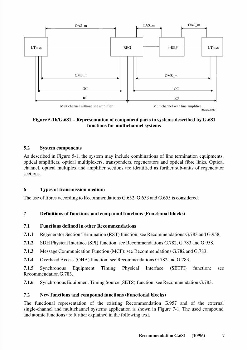
Figure 5-1b/G.681 – Representation of component parts to systems described by G.681functions for multichannel systems
5.2 System components
As described in Figure 5-1, the system may include combinations of line termination equipments,optical amplifiers, optical multiplexers, transponders, regenerators and optical fibre links. Opticalchannel, optical multiplex and amplifier sections are identified as further sub-units of regeneratorsections.
6 Types of transmission medium
The use of fibres according to Recommendations G.652, G.653 and G.655 is considered.
7 Definitions of functions and compound functions (Functional blocks)
7.1 Functions defined in other Recommendations
7.1.1 Regenerator Section Termination (RST) function: see Recommendations G.783 and G.958.
7.1.2 SDH Physical Interface (SPI) function: see Recommendations G.782, G.783 and G.958.7.1.3 Message Communication Function (MCF): see Recommendations G.782 and G.783.
7.1.4 Overhead Access (OHA) function: see Recommendations G.782 and G.783.
7.1.5 Synchronous Equipment Timing Physical Interface (SETPI) function: seeRecommendation G.783.
7.1.6 Synchronous Equipment Timing Source (SETS) function: see Recommendation G.783.
7.2 New functions and compound functions (Functional blocks)
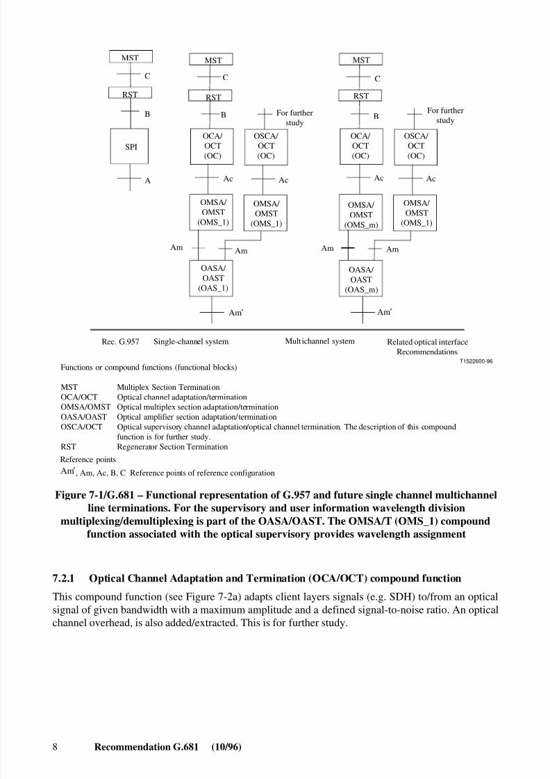
The functional representation of the existing Recommendation G.957 and of the externalsingle-channel and multichannel systems application is shown in Figure 7-1. The used compoundand atomic functions are further explained in the following text.
8/10/2019 ITU-T G.681
http://slidepdf.com/reader/full/itu-t-g681 14/39
8 Recommendation G.681 (10/96)
A
C
B
C
B
C
B
T1522600-96
MST
RST
MST
RST
Ac
Am
MST
RST
Ac
OASA/ OAST(OAS_m)
OMSA/ OMST
(OMS_m)
OMSA/ OMST
(OMS_1)
OCA/ OCT(OC)
OSCA/ OCT(OC)
OCA/ OCT(OC)
OSCA/ OCT(OC)
For further study
For further study
Am Am Am
OASA/ OAST
(OAS_1)
OMSA/ OMST
(OMS_1)
OMSA/ OMST
(OMS_1)
Rec. G.957 Single-channel system Mult ichannel system
Functions or compound functions (functional blocks)
MST Multiplex Section TerminationOCA/OCT Optical channel adaptation/termination
OMSA/OMST Optical multiplex section adaptation/terminationOASA/OAST Optical amplifier section adaptation/terminationOSCA/OCT Optical supervisory channel adaptation/optical channel termination. The description of this compound function is for further study.RST Regenerator Section Termination
Related optical interfaceRecommendations
Reference points
SPI
Ac Ac
Am ′ Am ′
, Am, Ac, B, C Reference points of reference configurationAm′
Figure 7-1/G.681 – Functional representation of G.957 and future single channel multichannelline terminations. For the supervisory and user information wavelength division
multiplexing/demultiplexing is part of the OASA/OAST. The OMSA/T (OMS_1) compoundfunction associated with the optical supervisory provides wavelength assignment
7.2.1 Optical Channel Adaptation and Termination (OCA/OCT) compound function
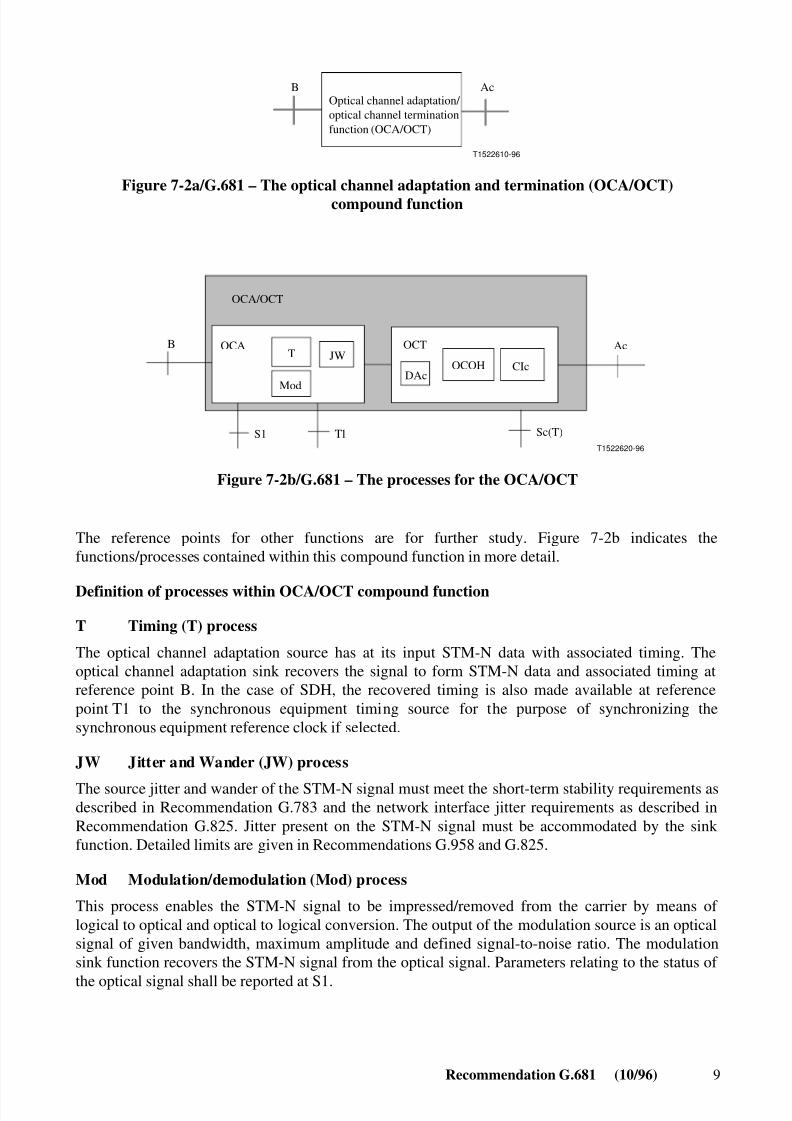
This compound function (see Figure 7-2a) adapts client layers signals (e.g. SDH) to/from an opticalsignal of given bandwidth with a maximum amplitude and a defined signal-to-noise ratio. An opticalchannel overhead, is also added/extracted. This is for further study.
8/10/2019 ITU-T G.681
http://slidepdf.com/reader/full/itu-t-g681 15/39
Recommendation G.681 (10/96) 9
T1522610-96
Optical channel adaptation/ optical channel terminationfunction (OCA/OCT)
B Ac
Figure 7-2a/G.681 – The optical channel adaptation and termination (OCA/OCT)compound function
TB
T1T1522620-96
JWOCOH
OCA/OCT
OCA
Mod
S1 Sc(T)
AcOCT
CIcDAc
Figure 7-2b/G.681 – The processes for the OCA/OCT
The reference points for other functions are for further study. Figure 7-2b indicates thefunctions/processes contained within this compound function in more detail.
Definition of processes within OCA/OCT compound function
T Timing (T) process
The optical channel adaptation source has at its input STM-N data with associated timing. Theoptical channel adaptation sink recovers the signal to form STM-N data and associated timing atreference point B. In the case of SDH, the recovered timing is also made available at referencepoint T1 to the synchronous equipment timing source for the purpose of synchronizing thesynchronous equipment reference clock if selected.
JW Jitter and Wander (JW) process
The source jitter and wander of the STM-N signal must meet the short-term stability requirements asdescribed in Recommendation G.783 and the network interface jitter requirements as described inRecommendation G.825. Jitter present on the STM-N signal must be accommodated by the sink function. Detailed limits are given in Recommendations G.958 and G.825.
Mod Modulation/demodulation (Mod) process
This process enables the STM-N signal to be impressed/removed from the carrier by means of logical to optical and optical to logical conversion. The output of the modulation source is an opticalsignal of given bandwidth, maximum amplitude and defined signal-to-noise ratio. The modulationsink function recovers the STM-N signal from the optical signal. Parameters relating to the status of
the optical signal shall be reported at S1.
8/10/2019 ITU-T G.681
http://slidepdf.com/reader/full/itu-t-g681 16/39
10 Recommendation G.681 (10/96)
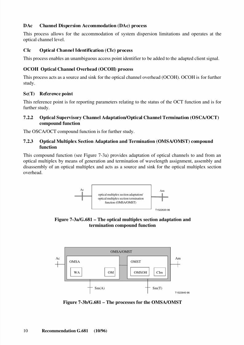
DAc Channel Dispersion Accommodation (DAc) process
This process allows for the accommodation of system dispersion limitations and operates at theoptical channel level.
CIc Optical Channel Identification (CIc) process
This process enables an unambiguous access point identifier to be added to the adapted client signal.OCOH Optical Channel Overhead (OCOH) process
This process acts as a source and sink for the optical channel overhead (OCOH). OCOH is for furtherstudy.
Sc(T) Reference point
This reference point is for reporting parameters relating to the status of the OCT function and is forfurther study.
7.2.2 Optical Supervisory Channel Adaptation/Optical Channel Termination (OSCA/OCT)compound function
The OSCA/OCT compound function is for further study.
7.2.3 Optical Multiplex Section Adaptation and Termination (OMSA/OMST) compoundfunction
This compound function (see Figure 7-3a) provides adaptation of optical channels to and from anoptical multiplex by means of generation and termination of wavelength assignment, assembly anddisassembly of an optical multiplex and acts as a source and sink for the optical multiplex sectionoverhead.
T1522630-96
AmAc
optical multiplex section adaptation/ optical multiplex section termination
function (OMSA/OMST)
Figure 7-3a/G.681 – The optical multiplex section adaptation andtermination compound function
T1522640-96
AcOMSA
WA OM
OMST
OMSOH CIm
Sm(A) Sm(T)
Am
OMSA/OMST
Figure 7-3b/G.681 – The processes for the OMSA/OMST

8/10/2019 ITU-T G.681
http://slidepdf.com/reader/full/itu-t-g681 17/39
Recommendation G.681 (10/96) 11
The reference points for other functions are for further study. Figure 7-3b indicates thefunctions/processes contained within this compound function in more detail.
Definition of processes within OMSA/OMST compound function
CIm Multiplex Channel Identification (CIm) process
This process enables a local channel identifier to be added to the optical channels contained in theoptical multiplex section.
OM Optical Multiplexing (OM) process
This process multiplexes/demultiplexes a number of optical channels together and separates them.For OMS_1 this process provides a one-to-one mapping (optical wavelength or frequencyconversion) and represents the WA process.
WA Wavelength assignment process
This process generates and terminates wavelength assignment to optical channels.
Wref Wavelength referencing process (Wref)
This process allows the verification of the channel wavelength within the multiplex. For furtherstudy.
OMSOH Optical Multiplex Section Overhead (OMSOH) process
This process acts as a source and sink for the Optical Multiplex Section Overhead (OMSOH). Forfurther study.
Sm(A) Reference point
This reference point is for reporting parameters relating to the status of the OMSA function and is forfurther study.
Sm(T) Reference point
This reference point is for reporting parameters relating to the status of the OMST function and is forfurther study.
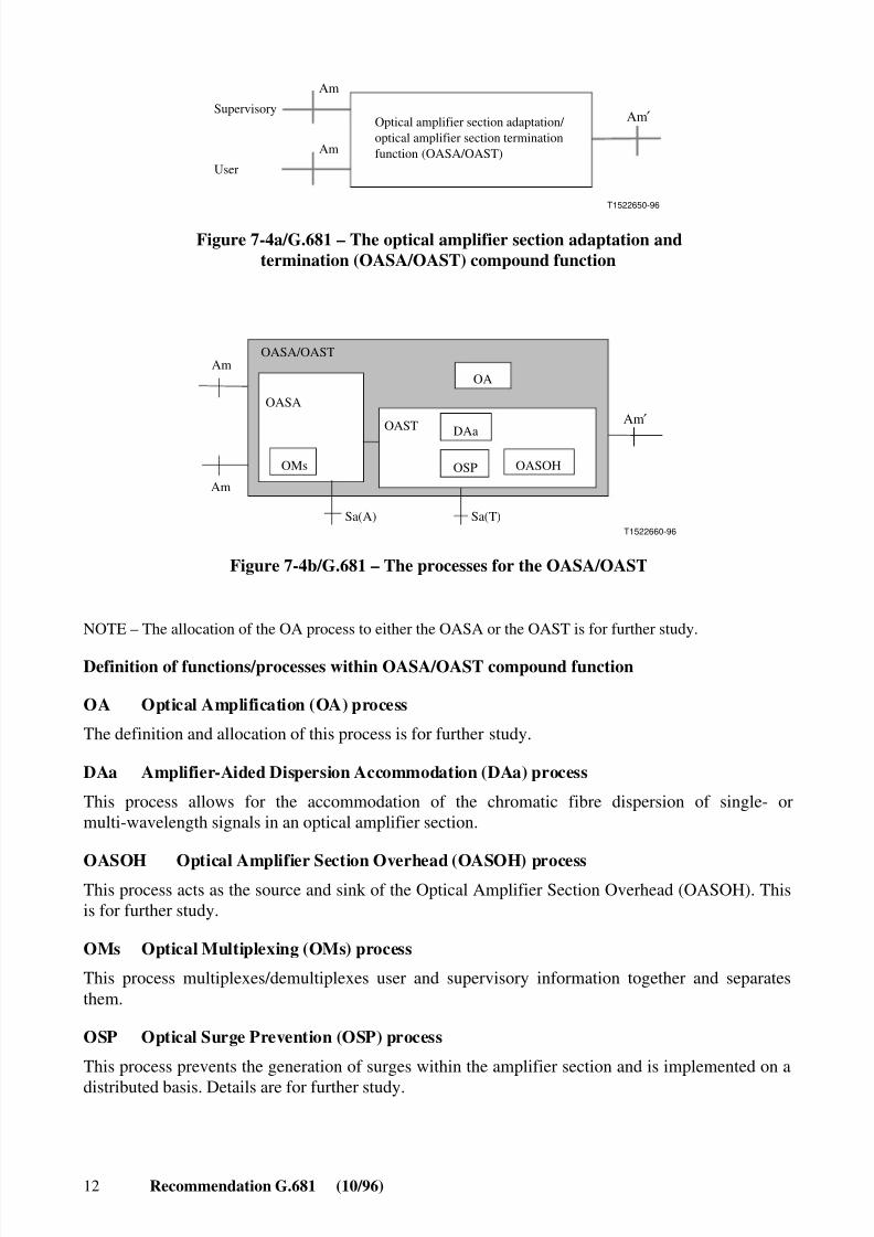
7.2.4 Optical Amplifier Section Adaptation and Termination (OASA/OAST) compoundfunction
The OASA/OAST (see Figure 7-4a) compound function, comprising Optical Amplification (OA)and fibre Dispersion Accommodation (DA) processes, provides the interface between the physicaltransmission medium at reference point Am ′ and the OMSA/OMST compound function at referencepoints Am. The interface signal at Am ′ shall be one of those specified in Recommendations G.690Series and the Recommendations on multichannel systems (see Figure 7-4a).
8/10/2019 ITU-T G.681
http://slidepdf.com/reader/full/itu-t-g681 18/39
12 Recommendation G.681 (10/96)
T1522650-96
Am
Supervisory
User
Optical amplifier section adaptation/ optical amplifier section terminationfunction (OASA/OAST)Am
Am ′
Figure 7-4a/G.681 – The optical amplifier section adaptation andtermination (OASA/OAST) compound function
T1522660-96
OASA/OASTAm
Am
OMs
OASA
OASTDAa
OSP
OA
OASOH
Sa(A) Sa(T)
Am ′
Figure 7-4b/G.681 – The processes for the OASA/OAST
NOTE – The allocation of the OA process to either the OASA or the OAST is for further study.
Definition of functions/processes within OASA/OAST compound function
OA Optical Amplification (OA) process
The definition and allocation of this process is for further study.
DAa Amplifier-Aided Dispersion Accommodation (DAa) process
This process allows for the accommodation of the chromatic fibre dispersion of single- ormulti-wavelength signals in an optical amplifier section.
OASOH Optical Amplifier Section Overhead (OASOH) processThis process acts as the source and sink of the Optical Amplifier Section Overhead (OASOH). Thisis for further study.
OMs Optical Multiplexing (OMs) process
This process multiplexes/demultiplexes user and supervisory information together and separatesthem.
OSP Optical Surge Prevention (OSP) process
This process prevents the generation of surges within the amplifier section and is implemented on adistributed basis. Details are for further study.

8/10/2019 ITU-T G.681
http://slidepdf.com/reader/full/itu-t-g681 19/39
Recommendation G.681 (10/96) 13
Sa(A) Reference point
This reference point is for reporting parameters relating to the status of the OASA function and is forfurther study.
Sa(T) Reference point
This reference point is for reporting parameters relating to the status of the OAST function and is forfurther study.
7.2.5 Other functions/processes for internetworking
7.2.5.1 Wref Wavelength reference process (Wref): see 7.2.3
7.2.5.2 EMF Equipment Management Function/process (EMF)
This function is for further study. The definition is similar to the definition of SEMF inRecommendations G.783 and G.784.
7.2.5.3 OHA Overhead access function/process (OHA)
The overhead access (OHA) function is defined in Recommendation G.783 for SDH equipment. Theextension of this function for optical non-SDH equipment is for further study.
7.2.5.4 MCF Message Communication Function (MCF)
This function is already defined in Recommendation G.783.
NOTE 1 – Annex A provides a graphical description for the links between the compound functions(functional blocks) described in 7.2 and a transport network architecture representation. It also provides adefinition of the layers and identifies the reference points and their relation to the compound functions(functional blocks).
NOTE 2 – Annex B provides a table that relates both the compound functions and the transport (adaptation ortermination) functions to the functions/processes defined in 7.2.
8/10/2019 ITU-T G.681
http://slidepdf.com/reader/full/itu-t-g681 20/39
14 Recommendation G.681 (10/96)
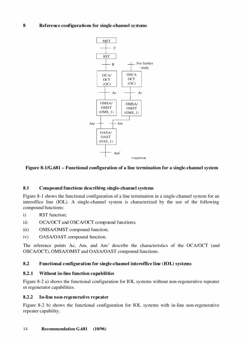
8 Reference configurations for single-channel systems
C
B
T1522670-96
MST
RST
Ac
Am
OCA/ OCT(OC)
OSCAOCT(OC)
For further study
OMSA/ OMST
(OMS_1)
OMSA/ OMST
(OMS_1)
OASA/ OAST
(OAS_1)
Ac
Am
Am ′
Figure 8-1/G.681 – Functional configuration of a line termination for a single-channel system
8.1 Compound functions describing single-channel systems
Figure 8-1 shows the functional configuration of a line termination in a single-channel system for aninteroffice line (IOL). A single-channel system is characterized by the use of the followingcompound functions:
i) RST function;
ii) OCA/OCT and OSCA/OCT compound functions;
iii) OMSA/OMST compound function;
iv) OASA/OAST compound function.
The reference points Ac, Am, and Am ′ describe the characteristics of the OCA/OCT (andOSCA/OCT), OMSA/OMST and OASA/OAST compound functions.
8.2 Functional configuration for single-channel interoffice line (IOL) systems
8.2.1 Without in-line function capabilities
Figure 8-2 a) shows the functional configuration for IOL systems without non-regenerative repeateror regenerator capabilities.
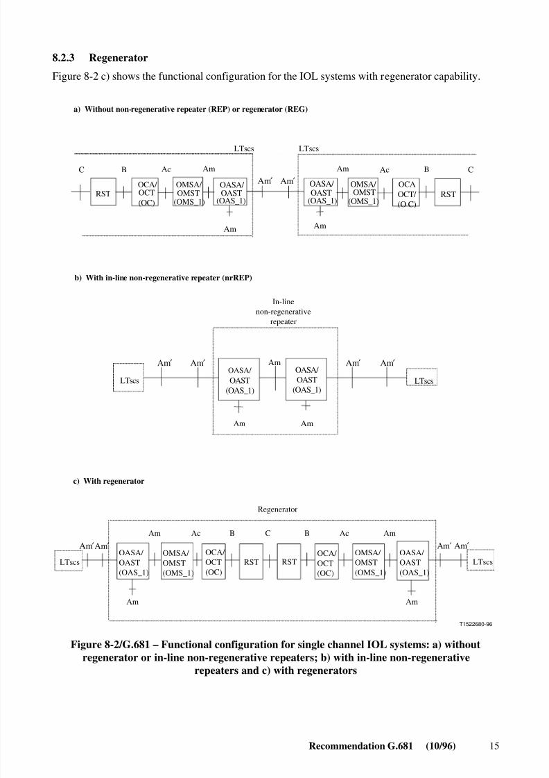
8.2.2 In-line non-regenerative repeater
Figure 8-2 b) shows the functional configuration for IOL systems with in-line non-regenerativerepeater capability.
8/10/2019 ITU-T G.681
http://slidepdf.com/reader/full/itu-t-g681 21/39
Recommendation G.681 (10/96) 15
8.2.3 Regenerator
Figure 8-2 c) shows the functional configuration for the IOL systems with regenerator capability.
T1522680-96
LTscs
Am
LTscs
Am Am
OASA/ OAST
(OAS_1)
OASA/ OAST
(OAS_1)
RSTRST
Am Am
BAc C
LTscs
AmB AcC
LTscs
Am
OCAOCT/ (O C)
LTscsOASA/ OAST(OAS_1)
OMSA/ OMST(OMS_1)
OCA/ OCT(OC)
RST RSTOCA/ OCT(OC)
OMSA/ OMST(OMS_1)
OASA/ OAST(OAS_1)
LTscs
Am Ac B C B Ac Am
Am Am
OMSA/ OMST
(OMS_1)
c) With regenerator
b) With in-line non-regenerative repeater (nrREP)
a) Without non-regenerative repeater (REP) or regenerator (REG)
Regenerator
In-linenon-regenerative
repeater
OASA/ OAST
(OAS_1)
OASA/ OAST
(OAS_1)
OMSA/ OMST
(OMS_1)
OCA/ OCT(OC)
Am′ Am ′
Am′ Am′Am′ Am′
Am′ Am ′ Am ′ Am ′
Figure 8-2/G.681 – Functional configuration for single channel IOL systems: a) withoutregenerator or in-line non-regenerative repeaters; b) with in-line non-regenerative
repeaters and c) with regenerators
8/10/2019 ITU-T G.681
http://slidepdf.com/reader/full/itu-t-g681 22/39
16 Recommendation G.681 (10/96)
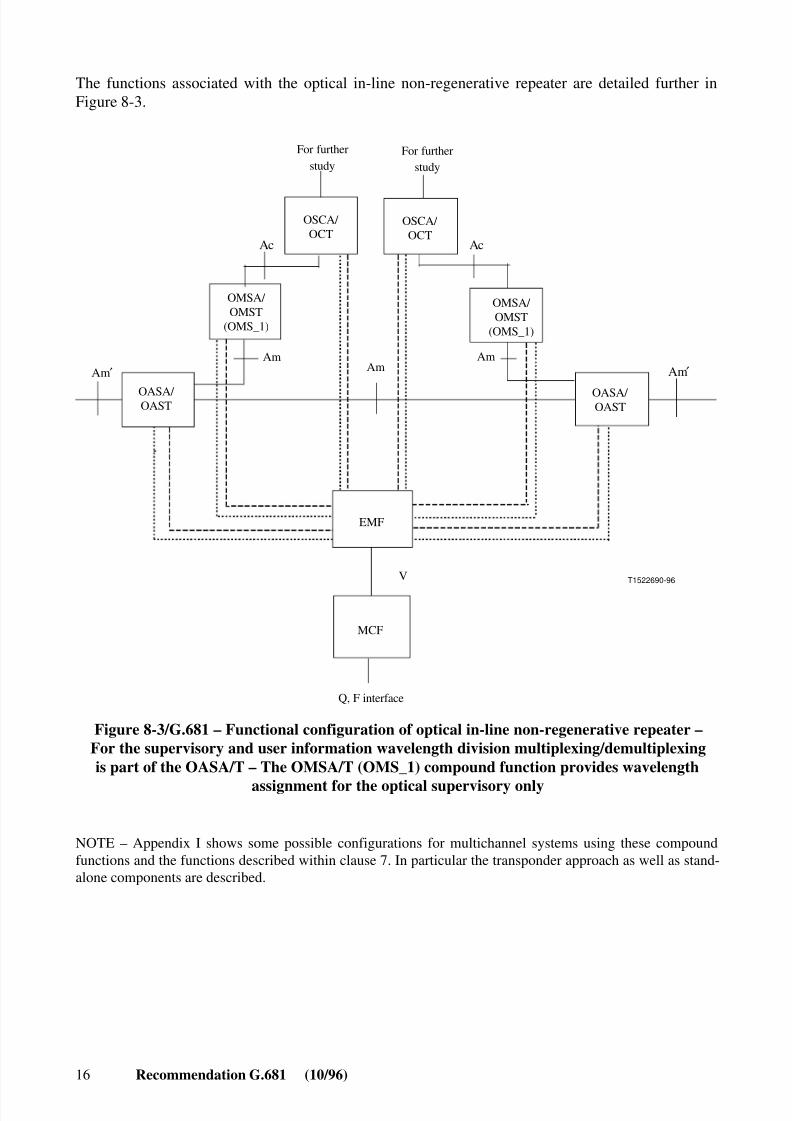
The functions associated with the optical in-line non-regenerative repeater are detailed further inFigure 8-3.
T1522690-96
AmAm Am
Ac Ac
For furtherstudy
For furtherstudy
Q, F interface
EMF
MCF
V
OSCA/ OCT
OSCA/ OCT
OMSA/ OMST
(OMS_1)
OMSA/ OMST
(OMS_1)
OASA/ OAST
OASA/ OAST
Am′Am ′
Figure 8-3/G.681 – Functional configuration of optical in-line non-regenerative repeater –For the supervisory and user information wavelength division multiplexing/demultiplexingis part of the OASA/T – The OMSA/T (OMS_1) compound function provides wavelength
assignment for the optical supervisory only
NOTE – Appendix I shows some possible configurations for multichannel systems using these compoundfunctions and the functions described within clause 7. In particular the transponder approach as well as stand-alone components are described.
8/10/2019 ITU-T G.681
http://slidepdf.com/reader/full/itu-t-g681 23/39
Recommendation G.681 (10/96) 17
9 Reference configurations for multichannel systems
9.1 Functional blocks describing multichannel systems
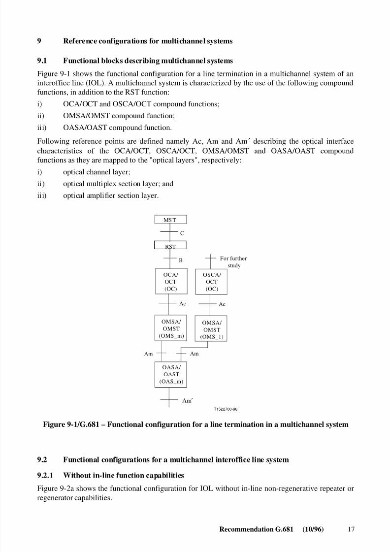
Figure 9-1 shows the functional configuration for a line termination in a multichannel system of aninteroffice line (IOL). A multichannel system is characterized by the use of the following compoundfunctions, in addition to the RST function:
i) OCA/OCT and OSCA/OCT compound functions;
ii) OMSA/OMST compound function;
iii) OASA/OAST compound function.
Following reference points are defined namely Ac, Am and Am ′ describing the optical interfacecharacteristics of the OCA/OCT, OSCA/OCT, OMSA/OMST and OASA/OAST compoundfunctions as they are mapped to the "optical layers", respectively:
i) optical channel layer;
ii) optical multiplex section layer; and
iii) optical amplifier section layer.
T1522700-96
Ac
Am
Ac
Am
OCA/ OCT
(OC)
OSCA/ OCT
(OC)
OMSA/ OMST
(OMS_1)
OMSA/ OMST
(OMS_m)
OASA/ OAST
(OAS_m)
MST
RST
C
B For further study
Am ′
Figure 9-1/G.681 – Functional configuration for a line termination in a multichannel system
9.2 Functional configurations for a multichannel interoffice line system
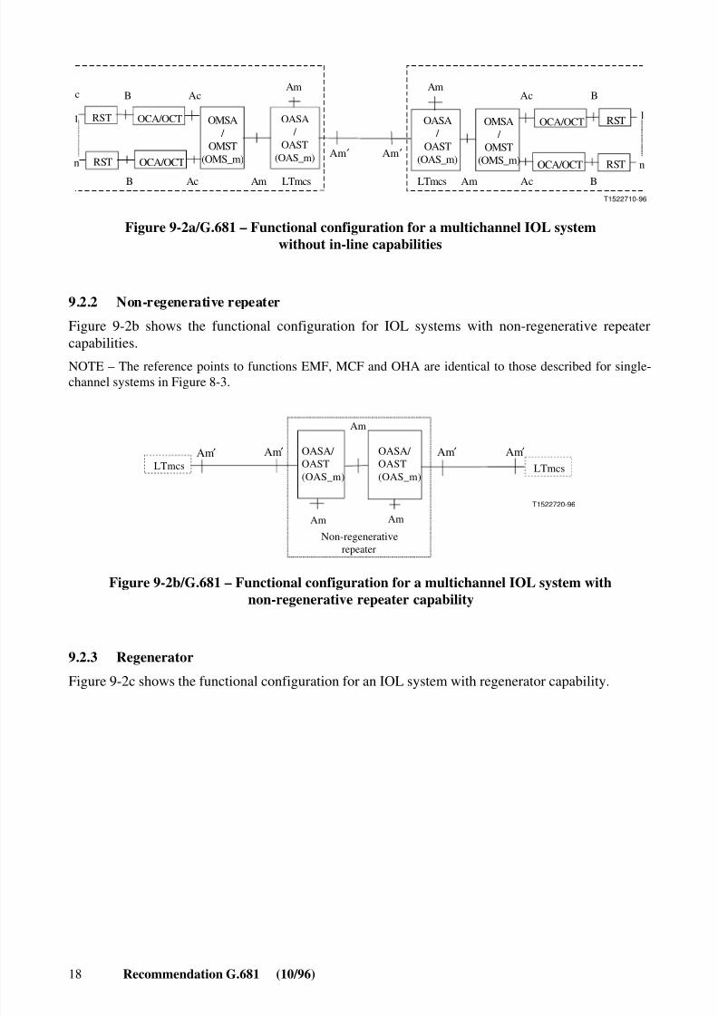
9.2.1 Without in-line function capabilities
Figure 9-2a shows the functional configuration for IOL without in-line non-regenerative repeater orregenerator capabilities.
8/10/2019 ITU-T G.681
http://slidepdf.com/reader/full/itu-t-g681 24/39
18 Recommendation G.681 (10/96)
c
B
B
1
n
B
B
1
n
T1522710-96
RST
Ac Am
RST
OCA/OCT
OCA/OCT
Ac
RST
AcAm
RST
OCA/OCT
OCA/OCT
Ac
LTmcsLTmcs
Am Am
OMSA /
OMST(OMS_m)
OMSA /
OMST(OMS_m)
OASA /
OAST(OAS_m)
OASA /
OAST(OAS_m)Am ′ Am ′
Figure 9-2a/G.681 – Functional configuration for a multichannel IOL systemwithout in-line capabilities
9.2.2 Non-regenerative repeater
Figure 9-2b shows the functional configuration for IOL systems with non-regenerative repeatercapabilities.
NOTE – The reference points to functions EMF, MCF and OHA are identical to those described for single-channel systems in Figure 8-3.
T1522720-96
Am
LTmcs LTmcs
Am Am
OASA/ OAST(OAS_m)
OASA/ OAST(OAS_m)
Non-regenerativerepeater
Am′ Am′ Am′ Am′
Figure 9-2b/G.681 – Functional configuration for a multichannel IOL system withnon-regenerative repeater capability
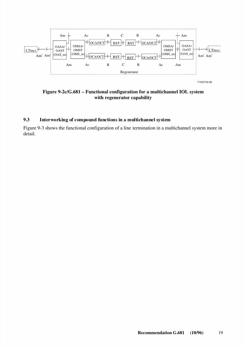
9.2.3 Regenerator
Figure 9-2c shows the functional configuration for an IOL system with regenerator capability.
8/10/2019 ITU-T G.681
http://slidepdf.com/reader/full/itu-t-g681 25/39
Recommendation G.681 (10/96) 19
T1522730-96
OCA/OCT RST
Am
B
OCA/OCT
Ac
Ac
RST
OCA/OCTRST
Am
B
OCA/OCT
Ac
Ac
RST
BC
C
LTmcs LTmcs
AmAm
OASA/ OAST
(OAS_m)
OMSA/ OMST
(OMS_m)
OMSA/ OMST
(OMS_m)
OASA/ OAST
(OAS_m)
B
Regenerator
Am ′ Am ′ Am ′ Am ′
Figure 9-2c/G.681 – Functional configuration for a multichannel IOL systemwith regenerator capability
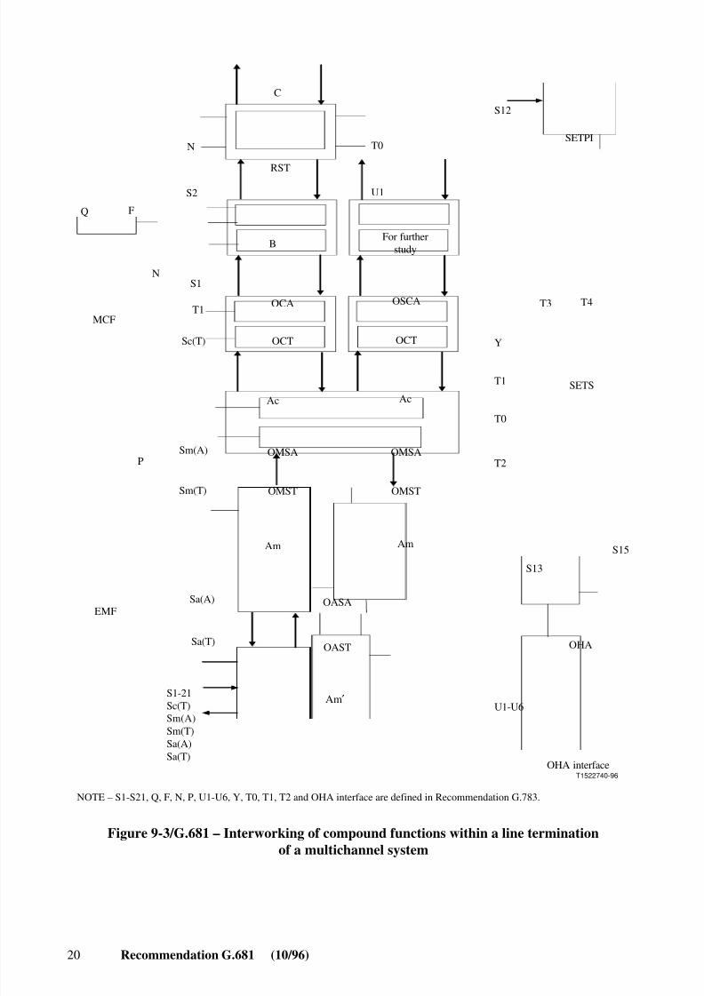
9.3 Interworking of compound functions in a multichannel systemFigure 9-3 shows the functional configuration of a line termination in a multichannel system more indetail.
8/10/2019 ITU-T G.681
http://slidepdf.com/reader/full/itu-t-g681 26/39
20 Recommendation G.681 (10/96)
T1522740-96
OAST
Am Am
EMF
OHA
S15
S13
U1-U6
OHA interface
Sa(T)
S1-21Sc(T)Sm(A)Sm(T)Sa(A)Sa(T)
OASASa(A)
OMSA
OMST
OMSA
OMST
OCA
OCT
OSCA
OCT
Ac Ac
MCF
P
SETS
T3 T4
Y
T0
T1
T2
S1
T1
Sc(T)
Sm(A)
Sm(T)
RST
C
B
Q F
N
N
S2
SETPI
S12
T0
U1
For furtherstudy
NOTE – S1-S21, Q, F, N, P, U1-U6, Y, T0, T1, T2 and OHA interface are defined in Recommendation G.783.
Am ′
Figure 9-3/G.681 – Interworking of compound functions within a line terminationof a multichannel system

8/10/2019 ITU-T G.681
http://slidepdf.com/reader/full/itu-t-g681 27/39

8/10/2019 ITU-T G.681
http://slidepdf.com/reader/full/itu-t-g681 28/39
8/10/2019 ITU-T G.681
http://slidepdf.com/reader/full/itu-t-g681 29/39
Recommendation G.681 (10/96) 23
T1522770-96
Optical signal at MPI-R
LOS detection at terminal "receiver"
Optical signal at MPI-S
Shutdown completed within 700 ms after t=0
Shutdown command after 500 ms after LOS recognitionLOS recognition time
t=0
At least 500 ms
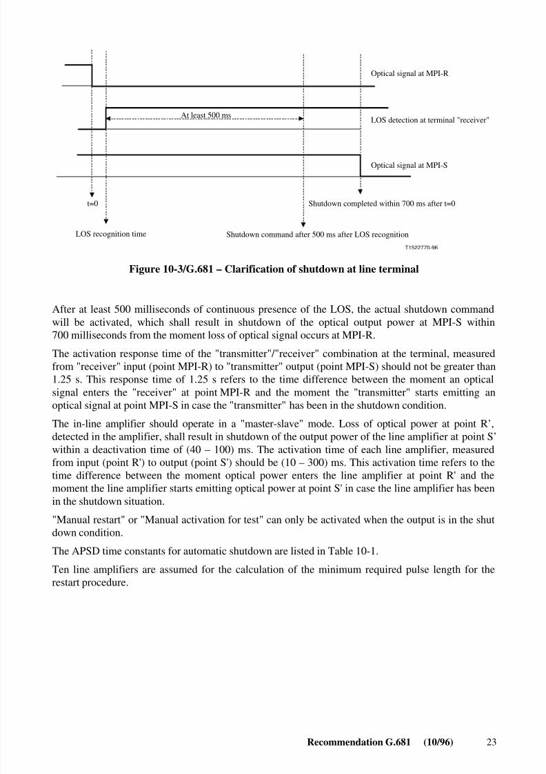
Figure 10-3/G.681 – Clarification of shutdown at line terminal
After at least 500 milliseconds of continuous presence of the LOS, the actual shutdown commandwill be activated, which shall result in shutdown of the optical output power at MPI-S within700 milliseconds from the moment loss of optical signal occurs at MPI-R.
The activation response time of the "transmitter"/"receiver" combination at the terminal, measuredfrom "receiver" input (point MPI-R) to "transmitter" output (point MPI-S) should not be greater than1.25 s. This response time of 1.25 s refers to the time difference between the moment an opticalsignal enters the "receiver" at point MPI-R and the moment the "transmitter" starts emitting an
optical signal at point MPI-S in case the "transmitter" has been in the shutdown condition.The in-line amplifier should operate in a "master-slave" mode. Loss of optical power at point R’,detected in the amplifier, shall result in shutdown of the output power of the line amplifier at point S’within a deactivation time of (40 – 100) ms. The activation time of each line amplifier, measuredfrom input (point R') to output (point S') should be (10 – 300) ms. This activation time refers to thetime difference between the moment optical power enters the line amplifier at point R' and themoment the line amplifier starts emitting optical power at point S' in case the line amplifier has beenin the shutdown situation.
"Manual restart" or "Manual activation for test" can only be activated when the output is in the shutdown condition.
The APSD time constants for automatic shutdown are listed in Table 10-1.
Ten line amplifiers are assumed for the calculation of the minimum required pulse length for therestart procedure.
8/10/2019 ITU-T G.681
http://slidepdf.com/reader/full/itu-t-g681 30/39
24 Recommendation G.681 (10/96)
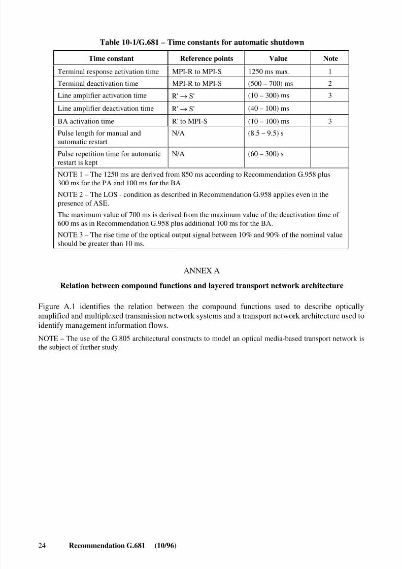
Table 10-1/G.681 – Time constants for automatic shutdown
Time constant Reference points Value Note
Terminal response activation time MPI-R to MPI-S 1250 ms max. 1
Terminal deactivation time MPI-R to MPI-S (500 – 700) ms 2
Line amplifier activation timeR'
→ S'
(10 – 300) ms 3
Line amplifier deactivation time R' → S' (40 – 100) ms
BA activation time R' to MPI-S (10 – 100) ms 3
Pulse length for manual andautomatic restart
N/A (8.5 – 9.5) s
Pulse repetition time for automaticrestart is kept
N/A (60 – 300) s
NOTE 1 – The 1250 ms are derived from 850 ms according to Recommendation G.958 plus300 ms for the PA and 100 ms for the BA.
NOTE 2 – The LOS - condition as described in Recommendation G.958 applies even in thepresence of ASE.
The maximum value of 700 ms is derived from the maximum value of the deactivation time of 600 ms as in Recommendation G.958 plus additional 100 ms for the BA.
NOTE 3 – The rise time of the optical output signal between 10% and 90% of the nominal valueshould be greater than 10 ms.
ANNEX A
Relation between compound functions and layered transport network architecture
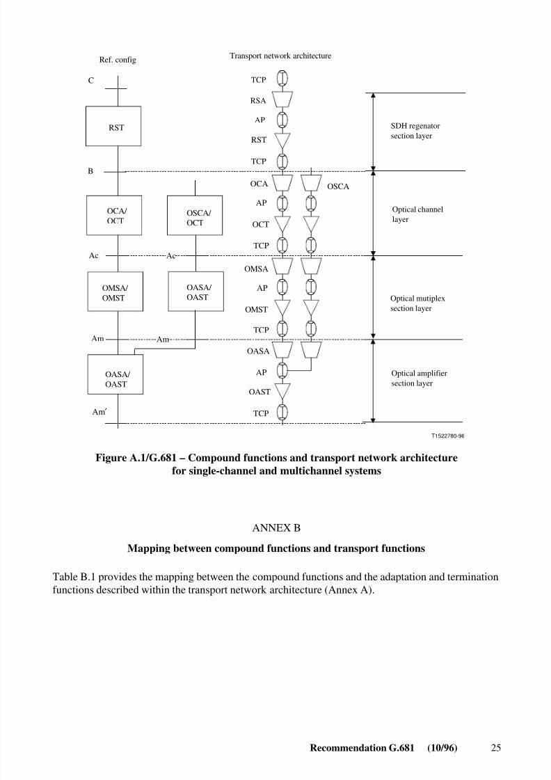
Figure A.1 identifies the relation between the compound functions used to describe opticallyamplified and multiplexed transmission network systems and a transport network architecture used toidentify management information flows.
NOTE – The use of the G.805 architectural constructs to model an optical media-based transport network isthe subject of further study.
8/10/2019 ITU-T G.681
http://slidepdf.com/reader/full/itu-t-g681 31/39
Recommendation G.681 (10/96) 25
T1522780-96
OMSAAP
AP
OAST
TCP
Optical amplifiersection layer
AmAmTCP
OASA
OASA/ OAST
OASA/ OAST
OMSA/ OMST Optical mutiplex
section layerOMST
C
B
Ref. config Transport network architecture
Ac
OCA
OCT
AP
TCP
RST
AP
RSA
TCP
TCPAc
OSCA
OCA/ OCT
OSCA/ OCT
Optical channellayer
SDH regenator
section layer
RST
Am ′
Figure A.1/G.681 – Compound functions and transport network architecturefor single-channel and multichannel systems
ANNEX B
Mapping between compound functions and transport functions
Table B.1 provides the mapping between the compound functions and the adaptation and terminationfunctions described within the transport network architecture (Annex A).
8/10/2019 ITU-T G.681
http://slidepdf.com/reader/full/itu-t-g681 32/39
26 Recommendation G.681 (10/96)
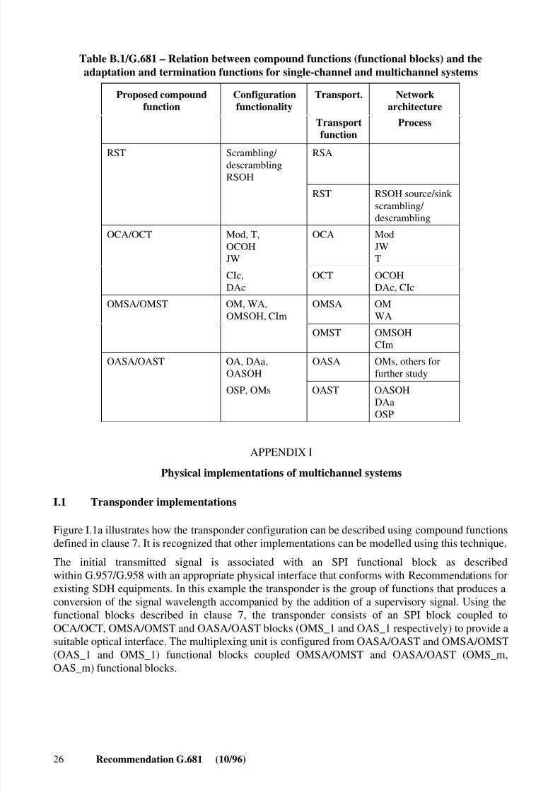
Table B.1/G.681 – Relation between compound functions (functional blocks) and theadaptation and termination functions for single-channel and multichannel systems
Proposed compoundfunction
Configurationfunctionality
Transport. Networkarchitecture
Transport
function
Process
RST Scrambling/ descramblingRSOH
RSA
RST RSOH source/sink scrambling/ descrambling
OCA/OCT Mod, T,OCOHJW
OCA ModJWT
CIc,DAc
OCT OCOHDAc, CIc
OMSA/OMST OM, WA,OMSOH, CIm
OMSA OMWA
OMST OMSOHCIm
OASA/OAST OA, DAa,OASOH
OASA OMs, others forfurther study
OSP, OMs OAST OASOHDAa
OSP
APPENDIX I
Physical implementations of multichannel systems
I.1 Transponder implementations
Figure I.1a illustrates how the transponder configuration can be described using compound functionsdefined in clause 7. It is recognized that other implementations can be modelled using this technique.
The initial transmitted signal is associated with an SPI functional block as describedwithin G.957/G.958 with an appropriate physical interface that conforms with Recommendations forexisting SDH equipments. In this example the transponder is the group of functions that produces aconversion of the signal wavelength accompanied by the addition of a supervisory signal. Using thefunctional blocks described in clause 7, the transponder consists of an SPI block coupled toOCA/OCT, OMSA/OMST and OASA/OAST blocks (OMS_1 and OAS_1 respectively) to provide asuitable optical interface. The multiplexing unit is configured from OASA/OAST and OMSA/OMST(OAS_1 and OMS_1) functional blocks coupled OMSA/OMST and OASA/OAST (OMS_m,OAS_m) functional blocks.
8/10/2019 ITU-T G.681
http://slidepdf.com/reader/full/itu-t-g681 33/39
Recommendation G.681 (10/96) 27
T1522790-96
A
A
SP I SPI
AmAmAm
OMS_1
OAS_1 OAS_1 OAS_m
OMS_mOMS_1
Ac Ac
RST
BB
OCA/
OCTMultiplexer
Transponder
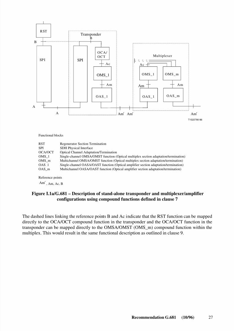
Functional blocks
RST Regenerator Section TerminationSPI SDH Physical InterfaceOCA/OCT Optical Channel Adaptation/TerminationOMS_1 Single-channel OMSA/OMST function (Optical multiplex section adaptation/termination)OMS_m Multichannel OMSA/OMST function (Optical multiplex section adaptation/termination)OAS_1 Single-channel OASA/OAST function (Optical amplifier section adaptation/termination)OAS_m Multichannel OASA/OAST function (Optical amplifier section adaptation/termination)
Reference points
Am′ Am′ Am′
, Am, Ac, BAm ′
Figure I.1a/G.681 – Description of stand-alone transponder and multiplexer/amplifierconfigurations using compound functions defined in clause 7
The dashed lines linking the reference points B and Ac indicate that the RST function can be mappeddirectly to the OCA/OCT compound function in the transponder and the OCA/OCT function in thetransponder can be mapped directly to the OMSA/OMST (OMS_m) compound function within themultiplex. This would result in the same functional description as outlined in clause 9.
8/10/2019 ITU-T G.681
http://slidepdf.com/reader/full/itu-t-g681 34/39
28 Recommendation G.681 (10/96)
T1522800-96
C
RST
B
AcAc
Am
xM
AmAm
OMS_1 OMS_1 OMS_m
OAS_1 OAS_1 OAS_m
OCA/ OCT Multiplexer
Single-channelsystem
Am′
Am ′ Am ′
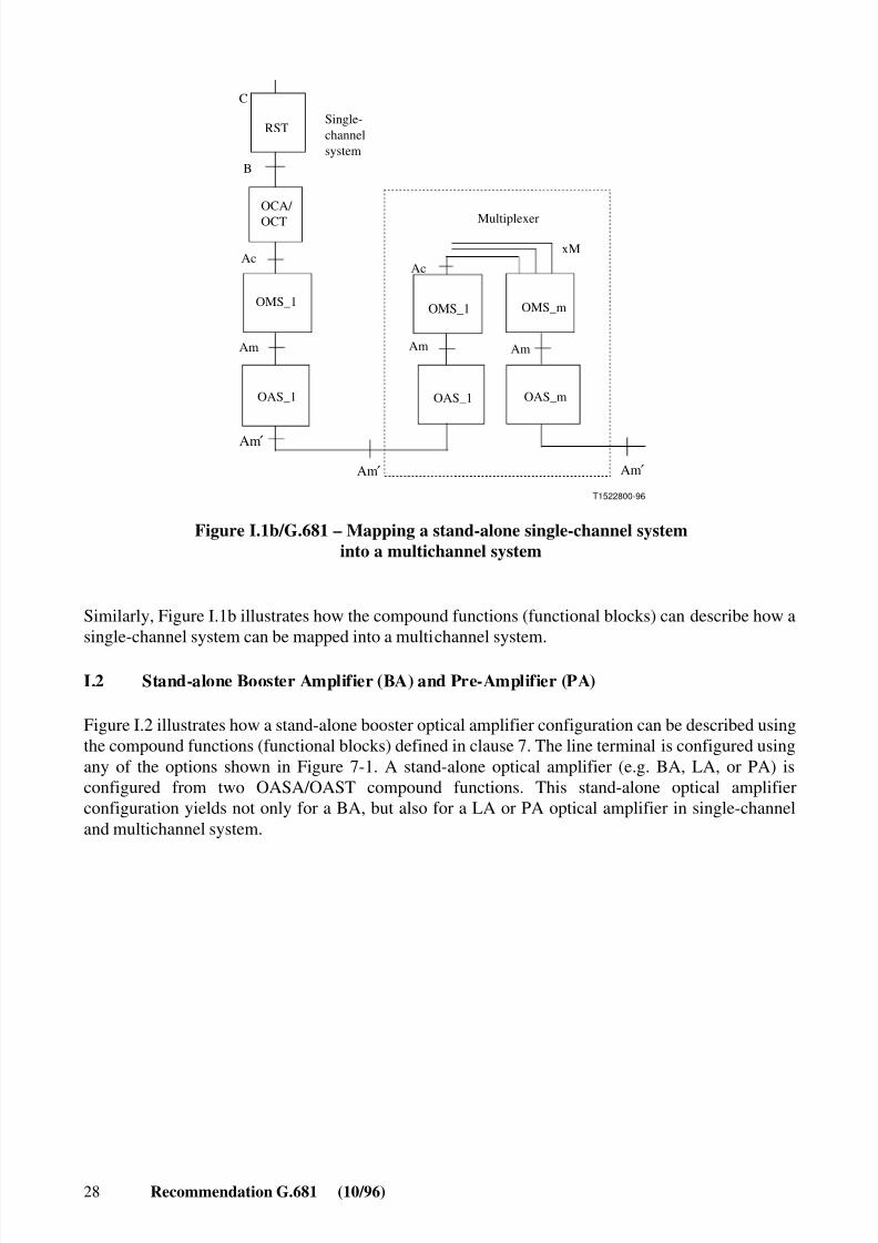
Figure I.1b/G.681 – Mapping a stand-alone single-channel systeminto a multichannel system
Similarly, Figure I.1b illustrates how the compound functions (functional blocks) can describe how asingle-channel system can be mapped into a multichannel system.
I.2 Stand-alone Booster Amplifier (BA) and Pre-Amplifier (PA)
Figure I.2 illustrates how a stand-alone booster optical amplifier configuration can be described usingthe compound functions (functional blocks) defined in clause 7. The line terminal is configured usingany of the options shown in Figure 7-1. A stand-alone optical amplifier (e.g. BA, LA, or PA) isconfigured from two OASA/OAST compound functions. This stand-alone optical amplifierconfiguration yields not only for a BA, but also for a LA or PA optical amplifier in single-channeland multichannel system.

8/10/2019 ITU-T G.681
http://slidepdf.com/reader/full/itu-t-g681 35/39
Recommendation G.681 (10/96) 29
T1522810-96
OASA /
OAST
OASA /
OAST
Am
LT ofsomesort
Stand-alone BAOFA
Am′ Am′ Am′
Figure I.2/G.681 – Description of stand-alone optical amplifier configuration using thecompound functions (functional blocks) defined in clause 7
A symmetrical configuration applies at the receiver side with a pre-amplifier instead of the boosteramplifier.
APPENDIX II
Realizations of new functions
II.1 Optical Amplification (OA) function
The OA function as OASA/OAST compound function is introduced into Recommendation G.681,single-channel and multichannel systems for the line termination (LT), the regenerator (REG) and forthe optical non-regenerative repeater (nrREP) in single-channel and multichannel optical interofficeline systems up to STM-64 bit rate.
Physical realizations of the OA function in SDH equipments or systems up to the STM-64 level canbe:
– physically integrated together with the E/O or O/E function as optically amplified;
– transmitter (OAT) or as Optically Amplified Receiver (OAR), respectively; and
– implemented in a specific stand-alone equipment (booster amplifier, pre-amplifier and line
amplifier).Optical amplifier characteristics, especially those of Optical Fibre Amplifiers (OFAs), are defined inRecommendations G.661, G.662 and G.663.
Optical amplifiers are implemented as Optical Fibre Amplifiers (OFAs) and as Semi-conductorOptical Amplifiers (SOAs). Proposed OFAs are the Erbium-doped fibre amplifier (EDFA) or theErbium-doped fluoride fibre amplifier (EDFFA) for the 1550 nm wavelength region and thepraseodymium-doped fluoride-fibre amplifier (PDFA) for the 1310 nm fibre window. Also a SOAfor the 1310 nm window is in discussion. These optical amplifiers can be a Booster Amplifier (BA)on the transmitter side and a Pre-Amplifier (PA) on the receiver side of a LT or REG as well as aLine Amplifier (LA) for instance as implementation of an optical non-regenerative repeater (nrREP).

8/10/2019 ITU-T G.681
http://slidepdf.com/reader/full/itu-t-g681 36/39
30 Recommendation G.681 (10/96)
The introduction of the OA function into LT, REG and nrREP functional groups will lead to newinteroffice line system structures:
– LT(OA)/nrREP(OA)/LT(OA); and
– LT(OA)/nrREP(OA)/REG(OA)/nrREP(OA)/LT(OA).
II.2 Dispersion Accommodation (DA) functionInteroffice line systems, regenerator sections and optical amplifier (non-regenerative repeater)sections require for a higher bit rate (e.g. STM-64) and a greater line length or repeater span (e.g. 80,120 or 160 km) not only Optical Amplifiers (OA), but also a certain fibre dispersion accommodation(DA) technique on the transmitter and receiver side of a line termination (LT) or of anoptical/electrical/optical regenerator (REG), as well as on the input and output side of anon-regenerative repeater (nrREP), to overcome fibre dispersion limitation.
The generic DA function allows different implementations of DA techniques. Identified have beenlinear fibre Dispersion Accommodation (DA) techniques like:
– Dispersion Supported Transmission (DST) method applying optical FSK/ASK signalconversion along the fibre;
– linear pre-chirping technique in laser diode or external modulator;
– Passive Dispersion Compensator (PDC),
and non-linear fibre Dispersion Accommodation (DA) techniques utilizing non-linear fibre-opticeffects like:
– Self-Phase Modulation (SPM),
alone or in connection with:
– external AM or PM modulators (e.g. electro-absorption EA modulator or electro-optical
mach-zehnder MZ modulator).Other DA techniques, like:
– multilevel (e.g. duobinary) modulation; and
– mid-system spectral inversion (MSI) by four-wave-mixing (FWM),
are not specifically considered within the scope of this Recommendation.
APPENDIX III
Example of functional modelling for single-channel and multichannel systems
Some examples for the mapping of functional architectures on implementations are shown in thefollowing subclauses.
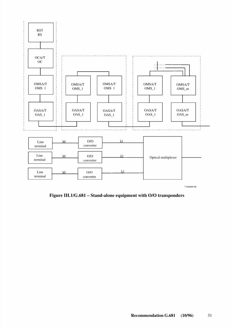
III.1 Example 1: Stand-alone equipment
See Figure III.1.
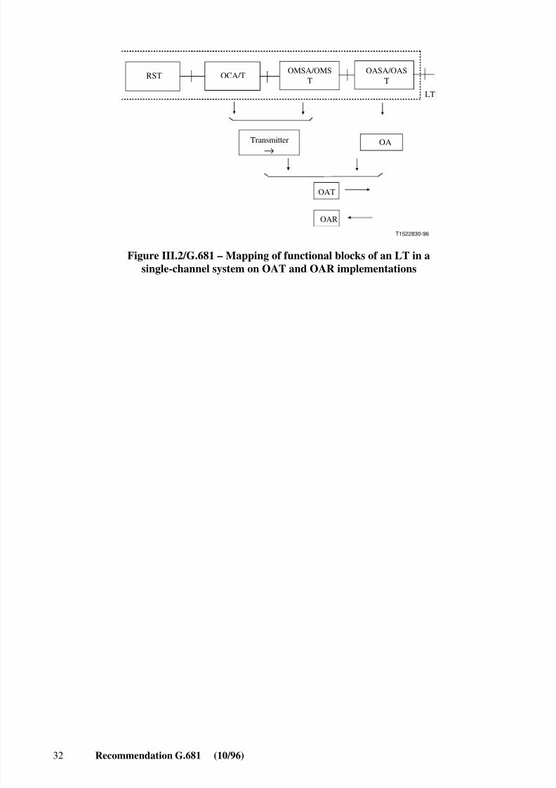
III.2 Example 2: Mapping of functional blocks of a line terminal in a single-channel systemon OAT and OAR implementations
See Figure III.2.
8/10/2019 ITU-T G.681
http://slidepdf.com/reader/full/itu-t-g681 37/39
Recommendation G.681 (10/96) 31
T1522820-96
RSTRS
OCA/TOC
OMSA/TOMS_1
OMSA/TOMS_1
OMSA/TOMS_1
OMSA/TOMS_1
OMSA/TOMS_m
OASA/T
OAS_m
OASA/T
OAS_1
OASA/T
OAS_1
OASA/T
OAS_1
OASA/T
OAS_1
λ0
λ0
λ0
λ1
λ2
λ3
Optical multiplexer
Lineterminal
Lineterminal
Lineterminal
O/Oconverter
O/Oconverter
O/Oconverter
Figure III.1/G.681 – Stand-alone equipment with O/O transponders
8/10/2019 ITU-T G.681
http://slidepdf.com/reader/full/itu-t-g681 38/39
32 Recommendation G.681 (10/96)
→
T1522830-96
RST OCA/T
OA
OAT
OAR
LT
OMSA/OMST
OASA/OAST
Transmitter
Figure III.2/G.681 – Mapping of functional blocks of an LT in asingle-channel system on OAT and OAR implementations

8/10/2019 ITU-T G.681
http://slidepdf.com/reader/full/itu-t-g681 39/39