ittc – recommended 7.6-02-09 procedures and guidelines ...that ensures the alignment of hour.its...
TRANSCRIPT

ITTC – Recommended Procedures and Guidelines
7.6-02-09 Page 1 of 25
Calibration of Load Cells Effective Date 2002
Revision 00
Updated / Edited by Approved
Quality Systems Group of the 28th ITTC
23rd ITTC 2002
Date 01/2017 Date 09/2002
ITTC Quality System Manual
Sample Work Instructions
Work Instructions
Calibration of Load Cells
7.6 Control of Inspection, Measuring and Test Equipment
7.6-02 Sample Work Instructions
7.6-02-09 Calibration of Load Cells

ITTC – Recommended Procedures and Guidelines
7.6-02-09 Page 2 of 25
Calibration of Load Cells Effective Date 2002
Revision 00
Table of Contents
1. PURPOSE ............................................ 4
2. TECHNICAL REQUIREMENTS ..... 4
2.1 Label ................................................. 4
2.2 General Condition ........................... 4
2.3 Classification. ................................... 4
2.4 Basic Characteristics. ...................... 4
2.4.1 Load characteristics: ................... 4
2.4.2 Electric characteristics: ............... 4
2.4.3 Temperature characteristics: ....... 4
2.4.4 Creep characteristics: ................. 6
2.5 Drift ................................................... 6
2.6 Other Relevant Technical Characteristics ................................. 6
3. CALIBRATION CONDITIONS ........ 6
3.1 Standard Calibration Condition. ... 6
3.2 Loading condition ............................ 7
3.3 Temperature balance period. ......... 7
3.4 Preheating. ....................................... 7
3.5 Atmospheric pressure. .................... 7
3.6 Relevant Technical Indices ............. 7
3.7 Precision Indices .............................. 8
3.8 Thermostat Container. .................... 8
4. ITEMS AND METHOD OF CALIBRATION FIRST TIME CALIBRATION FOR A NEW LOAD CELL OR AFTER REPAIR .............. 8
4.1 Preparations ..................................... 8
4.2 Calibration Method ......................... 8
4.3 Asymmetry ..................................... 10
4.4 Relative Deviation ......................... 10
4.5 Creep .............................................. 10
4.6 Influence of Temperature ............. 12
4.7 Random Calibration. .................... 14
4.8 Repeat Calibration. ....................... 14
4.9 Check - Accept Calibration .......... 14
4.10 Treatment of calibration result and calibration period .......................... 15
4.10.1 Initial Calibration ..................... 15
4.10.2 Re-Calibration .......................... 15
4.10.3 Calibration Period .................... 15
APPENDIX A : COVER PAGE FORMAT OF VERIFICATION CERTIFICATE ................................. 16
APPENDIX B : INSIDE PAGE FORMAT OF VERIFICATION CERTIFICATE ................................. 17
APPENDIX C : CALIBRATION RECORD OF LOAD CHARACTER ................................... 18
APPENDIX D : CALIBRATION RECORD OF LOAD CHARACTER ................................... 19
APPENDIX E : CALIBRATION RECORD OF ELECTRIC CHARACTER ................................... 21

ITTC – Recommended Procedures and Guidelines
7.6-02-09 Page 3 of 25
Calibration of Load Cells Effective Date 2002
Revision 00
APPENDIX F : CALIBRATION
RECORD OF TEMPERATURE CHARACTER ................................... 22
APPENDIX G : CALIBRATION RECORD OF CREEP ....................... 23
APPENDIX H : CALIBRATION RECORD OF NATURAL FREQUENCY .................................... 24
APPENDIX I : CALIBRATION RECORD OF ZERO DRIFT .............................. 25
Source: Verification regulation of load cell [Issued on July.18, 1985 and put into effect since May 1, 1986 by National Technical Bureau - JJG 391—85, National Measuring Verification Regulation of People’s Republic of China]
ITTC – Recommended Procedures and Guidelines
7.6-02-09 Page 4 of 25
Calibration of Load Cells Effective Date 2002
Revision 00
Calibration of Load Cells
1. PURPOSE
This procedure can be applied to the calibra-tion of strain gauge load cells for force measur-ing and weighing in both directions tension-, compression - or tension and compression serv-ing dual purpose (hereinafter referred to as load cell). It applies to new load cells, to gauges in service, and after repair. The calibration of other type of electric measuring load cells can be car-ried out in reference to this work instruction.
2. TECHNICAL REQUIREMENTS
2.1 Label
The load cell and its suspensions should be steadily fastened in a solid box. The name of the producer (or the producer sign), type, specifica-tion, production number, production date of the load cell should be marked on its nameplate.
2.2 General Condition
The load cell and its suspensions shouldn’t have any surface default which could affect its technical performance. The mounting parts should be all available. Normally they are not allowed to be exchanged.
The load cell should work well at room con-ditions.
2.3 Classification.
The classification of the grade of the load cell is shown in Table 1. The assessment period of the stability should be normally taken as 3 months, half year or one year, not less than 3 months.
2.4 Basic Characteristics.
The following 17 basic technical character-istics should be normally stated and available for each load cell.
2.4.1 Load characteristics:
nominal loading, safe overload capacity, sensitivity, linearity, hysteresis, repeatability and stability. The allowable error of sensitivity should be given for new or repaired load cells.
2.4.2 Electric characteristics:
input resistance, output resistance, insulation resistance, zero output, rated voltage.
2.4.3 Temperature characteristics:
influence of zero point temperature, influ-ence of temperature on output, temperature compensation range.

ITTC – Recommended Procedures and Guidelines
7.6-02-09 Page 5 of 25
Calibration of Load Cells Effective Date 2002
Revision 00
Table 1 Classification: Grade of Load Cells
Grade High precision Precision Normal Name
Code name
A B C
0.02S 0.03S 0.05S 0.1S 0.3S 0.5S 1S For cells with stability index given
0.02 0.03 0.05 0.1 0.3 0.5 1 For cells without stability index given
Allowable error I
L
±0.02 ±0.03 ±0.05 ±010 ±0.30
±0.50 ±1.0 L — linearity (%FS) H — hysteresis (%FS) R — repeatability (%FS) St — influence of temperature output (%FS/10K) Zt — influence of zero point temperature (%FS/10K) Cp — creep (%FS/30min)
H R
St / /
Zt / /
Cp / /
II Sb ±0.04 ±0.06 ±0.10 ±0.20 ±0.60 ±1.0 ±2.0 Sb — stability of sensitivity (%FS/×month)
Note: (1) If the load cells of A and B grade temporarily cannot be calibrated covering the six main indexes of the allowable error I shown in Table 1, because of the limitation of the calibration condition, it is allowed that the grade may be determined on the basis of the calibration results of 4 indexes --- L、H、
R、Zt. (2) If it is difficult to rapidly increase loading or to keep the load constant by use of the standard force exerting machine or the loading equipment, the creep recovery Cr is allowed to be used instead of the creep Cp. Its allowable error is the same as the one of Cp.

ITTC – Recommended Procedures and Guidelines
7.6-02-09 Page 6 of 25
Calibration of Load Cells Effective Date 2002
Revision 00
Table 2
Grade A B C
Allowable error (%FS) ±1.0 ±2.0 ±5.0
2.4.4 Creep characteristics:
The manufacturer should normally supply 17 basic technical characteristics for each load cell. Normally the following 9 properties should be calibrated: sensitivity S, linearity L, hystere-sis H, repeatability R, zero output Z, influence of zero point temperature Zt, influence of output temperature St, creep Cp (or creep recovery Cr ) and stability Sb. Note: If the requirements of this clause temporarily cannot be met because of the limitation of the calibration condition, the manufacturer must at least supply the other 14 basic technical characteristics except stability, influence of output temperature and creep. The metrological department must at least calibrate the 5 technical characteristics of S、L、H、R and Z. The zero output of the load cell Z should com-ply with the data in Table 2.
2.5 Drift
At indoor conditions the percentage of the zero drift over the rated output of the load cell should over a time of 2 hours not exceed half of the acceptble error I shown in Table 1.
2.6 Other Relevant Technical Characteris-tics
The other relevant technical characteristics of the load cell (such as overload capacity, in-fluence of non-axial load, natural frequency, cir-culation life, influence of external magnetic fields, vibration resistance property) should meet the requirements of the relevant technical documents (such as relevant national standards, shop instructions etc.).
3. CALIBRATION CONDITIONS
3.1 Standard Calibration Condition.
The calibration must be carried out under the following conditions:
a) Ambient temperature: 20±2°. b) Relative humidity: ≤70%. c) Atmospheric pressure: 90~106 kPa
(680~800mmHg)
Note: (1) If the above standard calibration con-dition cannot be met, the calibration can be car-ried out under the following room conditions which should then be noted in the calibration re-port with the calibration result. The ambient temperature change must not exceed 1° per hour during the load cell calibration. This note is also

ITTC – Recommended Procedures and Guidelines
7.6-02-09 Page 7 of 25
Calibration of Load Cells Effective Date 2002
Revision 00
suitable as standard calibration condition in any other item of this work instruction.
Room condition:
d) Temperature: 20±10°. e) Relative humidity: ≤90%. f) Atmospheric pressure: 90~106 kPa
(680~800mmHg)
(2) Deviations of the relevant technical charac-teristics caused by the actual service condition should be noticed. The calibration results can be revised when necessary.
3.2 Loading condition
• The load cell should be installed in a way that ensures the alignment of its main shaft line and its loading shaft line so that the in-fluence of a loading declination or eccentric loading is reduced to a minimum.
• Compression
1. The quality of the loading contact surface must be taken care of for any loading device. Both the support surface and the bottom sur-face of the load cell should be smooth with-out any rusty erosion, bruise and impurity.
2. The load cell should normally have high, or low pressure-bearing cushions.
• Tension. The two ends of the load cell should have proper connection elements in-stalled.
3.3 Temperature balance period.
The load cell should be kept under the stand-ard calibration conditions for a time long enough to make sure that its temperature is sta-
ble and corresponds to the required standard cal-ibration condition. The period for the tempera-ture balance is suggested to be not less than 8h.
3.4 Preheating.
Before the calibration the load cell, the dis-play units, the load source and other accessories which are connected with it should be switched on for preheating the system The preheating du-ration should meet the specification of the man-ufacturer. The calibration should not be carried out until all parts are stable.
Note: Load cells , measuring meters or load sources for which no specification is available should normally be preheated for half to one hour.
3.5 Atmospheric pressure.
Changes of the atmospheric pressure which might obviously affect the zero output of the load cell should be noticed.
3.6 Relevant Technical Indices
The relevant technical indices of the stand-ard force-exerting device or the loading device for the load cell calibration should be in princi-ple three times those of the calibrated load cell. The proper standard force-measuring device and loading device should be selected on the basis of the calibration contents and the relevant indexes of the calibrated load cell.

ITTC – Recommended Procedures and Guidelines
7.6-02-09 Page 8 of 25
Calibration of Load Cells Effective Date 2002
Revision 00
3.7 Precision Indices
The precision indices of the used indication meters should be at least three times those of the calibrated load cell during calibration.
The precision indices of the used load source should be at least five times of those of the cali-brated load cell during calibration.
3.8 Thermostat Container.
The adjustable temperature range of the ther-mostat container should not be less than the tem-perature compensation range of the load cell. It should normally be within –30~+70°. The range of variation of the temperature of the environ-ment should normally not exceed ±1°. The tem-perature gradient should normally not exceed 3°/h.
4. ITEMS AND METHOD OF CALI-BRATION FIRST TIME CALIBRATION FOR A NEW LOAD CELL OR AFTER REPAIR
4.1 Preparations
• An exterior inspection can be done accord-ing to the requirement of item 2.2 of this pro-cedure.
• The zero drift Zd of the load cell within 2h should be measured after the load cell and its connected electronic devices have been pre-heated according item 3.4.
[ ]0 max 0 min 100 %FSdn
Z θ θθ−
= ⋅ (1)
where,
θ0max,θ0min --- the maximum and the minimum value of the zero output during the measuring time respectively.
θn --- The rated output of the load cell.
Note: This index is normally measured for one time, at most three times. The mean value will be taken as the final result.
4.2 Calibration Method
The characteristics of the load cell can be calibrated according to the following procedures.
• The ambient conditions and the calibrating conditions should be compared and checked if they meet the requirements given in item 3.
• The load cell should be put on the standard force-exerting machine and preloaded three times, up to the nominal load and then re-turned to zero each time.
Note: This item may not be carried out when the execution for the load characteristics of the load cell is not required under the condition of pre-loading.
• The electric driving mechanism may be in-spected or adjusted if necessary, the measur-ing range and the zero point of the indicating meter should be adjusted and the zero output should be read.
• On having pre-loaded three times, the formal calibration can start in one min.
• The load should be progressively increased up to the nominal one with the same incre-ment. Each load step should be kept for a
ITTC – Recommended Procedures and Guidelines
7.6-02-09 Page 9 of 25
Calibration of Load Cells Effective Date 2002
Revision 00
certain time and the output value may be read when it has stabilized.
Notes:
1. The load keeping time is recom-mended to be 5s, 15s, 30s and 1min 30s. The selection should be noted.
2. The load increment may be not equal, when the loading condition of the stand-ard force-exerting machine is limited. The first load step should normally be 10-20% of the nominal one.
3. The number of load steps must not be less than 5 (zero load is not included), 10 steps are recommended.
• Once the nominal load has been reached the same method can be used for progressive re-ducing. Each load step should be kept for a certain time and the output value may be read when it has stabilized.
• When the load returns to zero and stays there for 1 min., the zero output can then be read. The zero point of the indicating meter can be readjusted when necessary.
• The procedure of loading and unloading should be carried out at least three times.
• The relevant technical indices (see Figure 1) can be calculated from the following formu-lae with the above calibration result.
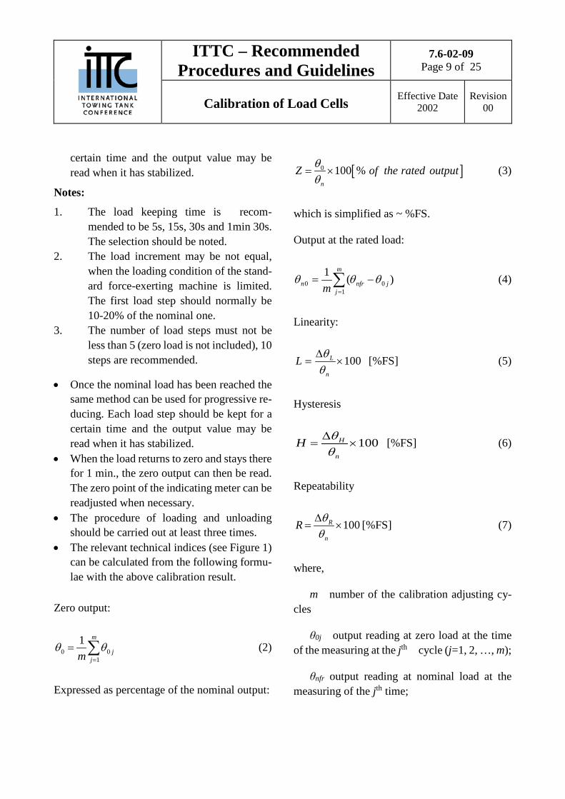
Zero output:
0 01
1 m
jjm
θ θ=
= ∑ (2)
Expressed as percentage of the nominal output:
[ ]0 % 0 10n
of the rated ou pZ t utθθ
= × (3)
which is simplified as ~ %FS.
Output at the rated load:
∑=
−=m
jjnfrn m 1
00 )(1 θθθ (4)
Linearity:
100×∆
=n
LLθθ [%FS] (5)
Hysteresis
100H
n
H θθ∆
= × [%FS] (6)
Repeatability
100R
n
R θθ∆
= × [%FS] (7)
where,
m number of the calibration adjusting cy-cles
θ0j output reading at zero load at the time of the measuring at the jth cycle (j=1, 2, …, m);
θnfr output reading at nominal load at the measuring of the jth time;

ITTC – Recommended Procedures and Guidelines
7.6-02-09 Page 10 of 25
Calibration of Load Cells Effective Date 2002
Revision 00
ΔθL the maximum value of the deviation between the mean advance calibration curve and the straight line of two mean end points;
ΔθH the maximum value of the deviation between the return mean calibration curve and the advance one;
ΔθR the maximum value of the output range at each load point during the repeat-cali-bration.
Figure 1
So output signal, Fn rated load, θn rated out-put, θ0 zero output, ΔθR repeatability, ΔθH hys-teresis, ΔθL linearity,
l calibration curves, 2 output
4.3 Asymmetry
After the loading – unloading procedure has been finished, load cells of grade A should be turned 3times around their main shaft line by 900
respectively, i.e. the angle between the pressure cushion position vector of the standard force-ex-erting machine and the load cell position vector (simplified as direction angle) should be changed from 00 to 900, 1800, and 2700. After each turn the load should be exerted on the load
cell up to the nominal one, the rated output θnφ can be read. The arithmetic mean of θnφ at 4 di-rection positions (including 00 direction position) is taken as the rated output of the load cell θn. The rated output θn of load cells of grade B or C is θn= θn0.
4.4 Relative Deviation
The relative deviation Se between the nomi-nal sensitivity value S0 and the actual measured one S can be calculated and judged whether it meets the requirement for the acceptable error of sensitivity with the following formulae:
US nθ= [mV/V] (8)
0 100eS SS
S−
= × [%FS] (9)
where, U is the mean value of the voltage of the load cell.
4.5 Creep
Creep and creep recovery can be calibrated by the following procedures.
• The environmental condition and the cali-brating condition should checked whether they meet the requirements given in chapter 3.
• The load cell should be installed on the standard force-exerting machine and pre-loaded three times, up to the nominal load and then returned to the zero point each time. The pre-load should not be exerted on a load cell, at least within 24 hours before the cali-bration if the exertion of the pre-load affects the calibration result.
ITTC – Recommended Procedures and Guidelines
7.6-02-09 Page 11 of 25
Calibration of Load Cells Effective Date 2002
Revision 00
• The electric drive may be inspected and ad-
justed if necessary, the measuring range and zero point of the indicating meter should be adjusted and the zero output should be read
• The rated load should be exerted as fast as possible (the loading duration should not usually exceed 5s, static weights are the best), after loading(5s~10s is recommended) the output should be read. Then the follow-ing outputs should read at fix time intervals within 30 min.
• The load should be unloaded as fast as pos-sible (the unloading duration shouldn’t usu-ally exceed 5s), after unloading (5s~10s is recommended) the output should be read. Then the following outputs should be read in fix time intervals within 30 min.
• The relevant technical indices (see Figure 2) can be calculated by the following formulae
Creep 10032 ×−
=n
PCθθθ [%FS] (10)
Creep recovery 10065 ×−
=n
rCθθθ [%FS] (11)
Notes: 1. When creep CP is given, the loading time
(t1-t0) and the first reading time (t2-t1) should be recorded. When the creep re-covery Cr is given, the unloading time (t4-t3) and the first reading time (t5-t4) should be noted.
2. This index is usually measured one time, at most 3 times. The mean value can be taken as the final result for this index. The time interval between two consecu-tive measurements should not be less than half an hour.

ITTC – Recommended Procedures and Guidelines
7.6-02-09 Page 12 of 25
Calibration of Load Cells Effective Date 2002
Revision 00
Figure 2
1 output, 2 positive creep, 3 negative creep, 4 positive creep recovery, 5 negative creep recovery t1-t0 --- the duration from zero load to rated load; t2-t1 --- the duration from the rated load being reached to the first reading (5~10s); t3-t2 --- the duration of the creep observation (30 min); t4-t3 --- the duration of unloading (nearly equals to t1-t0); t5-t4 --- the duration between the zero load being reached and the first reading; t6-t5 --- the duration of the creep recovery observation (30min); θ0,θ2,θ3,θ5,θ6 --- the output readings relevant to the time t0、t2、t3、t5、t6.
4.6 Influence of Temperature
The influences of the difference between the temperatures at zero point and at the output can be calibrated by the following procedure:
• The ambient condition and the calibration condition should be compared with the cri-teria given in chapter 3.
• The load cell should be kept in the thermo-stat container of the standard force-exerting machine (usually with an attached cable of the load cell).
• The load cell should be preloaded three times up to the nominal load and then re-turned to zero point each time. One min after the preloading, the formal calibration can start.

ITTC – Recommended Procedures and Guidelines
7.6-02-09 Page 13 of 25
Calibration of Load Cells Effective Date 2002
Revision 00
• The electric driving mechanism may be in-
spected and adjusted if necessary, the meas-uring range and zero point of the indicating meter should be adjusted and the zero output should be read.
• When the nominal load is exerted, reached and kept for 30s, the output should then be read. After that, the load cell should be un-loaded down to zero and kept for 1 min, and then the zero output should be read. The electric driving mechanism and the zero point of the indicating meter may be re-ad-justed if necessary, the zero output should be read again. This procedure should be contin-uously carried out at least three times.
• The temperature of the thermostat should be increased to the upper range for the load cell. After the temperature is really stable, the above procedures should be repeated.
Note: It is acceptable that the calibration can be carried out at a temperature lower than the upper limit if the temperature of the thermostat cannot reach the upper limit of the compensation tem-perature range.
• The temperature of the thermostat should be decreased to the lower limit of the compen-sation temperature range of the load cell. Af-ter the temperature is stable, the above load-ing and unloading procedures should be re-peated.
Note: It is acceptable that the calibration can be carried out at a temperature higher than the lower limit if the temperature of the thermostat cannot reach the lower limit of the compensa-tion temperature range.
• The temperature of the thermostat should be returned to the standard calibration condi-tion. After the temperature is really stable, the above procedures should be repeated.
• The relevant technical indices can be calcu-lated by the following formulae.
100
10
00
×−
−
=sh
n
sh
th TTZ θθθ
[%FS/10K]
Influence of zero point temperature
100
10
00
×−
−
=sl
n
sl
tl TTZ θθθ
[%FS/10K] (12)
0 0( ) ( )
100
10
nh h ns s
nth
h sS T T
θ θ θ θθ
− − −
= ×−
[%FS/10K]
Influence of output Temperature
0 0( ) ( )
100
10
nl l ns s
ntl
l sS T T
θ θ θ θθ
− − −
= ×−
[%FS/10K]
(13)
Where,
Th, Ts, Tl the upper limit temperature、standard calibration temperature and the low limit tem-perature by the time of calibration respectively;
ITTC – Recommended Procedures and Guidelines
7.6-02-09 Page 14 of 25
Calibration of Load Cells Effective Date 2002
Revision 00
θ0h,θ0s,θ0l the relevant zero output average val-ues of Th, Ts and Tl respectively;
θnh,θns,θnl the relevant output reading average values of Th, Ts and Tl at the rated load respec-tively;
θn --- the rated output.
The bigger one of the absolute values of Zth and Ztl should be taken as the final influence value of the zero point temperature Zt.
The bigger one of the absolute values of Sth and Stl should be taken as the final influence value of the output temperature St.
Note:
(1) If the condition allows, the influences of the zero point temperature and the output tempera-ture can better be calibrated separately.
(2) If the calibration results at the standard tem-perature reached before and after the tempera-ture increasing and decreasing do not coincide, the calculation should be done using these two results. The bigger one of the absolute values should be taken as the final relevant temperature influence index.
4.7 Random Calibration.
For the same lot of load cells of the same type, same dimension, manufactured by the same factory, a random-calibration of zero drift, creep and influence of temperature is allowed. The random-calibration rate must be at least 10% (not less than 3 sets). The random-calibration is only usually suitable to the load cell of B and C
grade. The indices of the worst one must be taken as the one of this lot of load cells.
4.8 Repeat Calibration.
The examination of the exterior, calibration of the load characteristics and the influence of asymmetry should be done during a load cell re-peat-calibration. Z, L, H, R, the sensibility S2 and the stability Sb of this calibration can be calcu-lated upon the calibration results. Sb can be cal-culated by the following formula:
1002
21 ×−
=S
SSSb [%FS] (14)
where, S1 is the sensibility of the load cell meas-ured during the last calibration.
Note: When the calibrator thinks that the change of the other relevant indices from the first time calibration might exceed the allowable error for the original grade, the re-calibration of these in-dices is suggested. The result of the re-calibra-tion should be taken as one of the criteria for judging the grade of the load cell.
4.9 Check - Accept Calibration
New load cells should be in principle cali-brated on the basis of above procedure (item 4.1 to 4.6). If the manufacturer and the user sign other agreements on checking and acceptance, the first calibration can be done following that agreement.
ITTC – Recommended Procedures and Guidelines
7.6-02-09 Page 15 of 25
Calibration of Load Cells Effective Date 2002
Revision 00
4.10 Treatment of calibration result and
calibration period
4.10.1 Initial Calibration
For a load cell which is calibrated the first time, the grade can be determined upon the cal-ibration results and a calibration certificate will be issued normally containing the following ten basic technical indices S, Z, L, H, R, Zt, St, Cp, Se, Zd etc..
Note:
(1) If Z or Zd from the calibration result exceed the values for the relevant grade determination in Table 1, the grade of the load cell grade can be lowered, or the grade stays undetermined with the above-mentioned ten basic technical in-dices given.
(2) The output mean values of the advance and the return may also be attached to the calibration results respectively based on the actual need .
4.10.2 Re-Calibration
For a load cell which is re-calibrated, the grade can be determined by a comparison of L,
H, R, Sb obtained this time and Zt, St, Cp (or Cr), Zd obtained last time with the grade given in Ta-ble 1, then a calibration certificate will be issued containing six indices: S, Z, L, H, R, and Sb and the other technical indices which were obtained by the first calibration adopted. For the stability Sb, the calibration time interval (taken as ~%FS/×month or ~%FS/×year) should be noted.
The treatment of the calibration results can be done the same way as the initial calibration for a new load cell which has been calibrated ac-cording to paragraphs 4.1 - 4.6 . For a new load cell which has been calibrated according to a check-accept agreement between the manufac-turer and the user, the final calibration results can be supplied upon the agreement, the grade can be determined using this work instruction as reference.
4.10.3 Calibration Period
The calibration period of the load cell can be divided into three months, half-year or one year depending on the calibration result of its stabil-ity.

ITTC – Recommended Procedures and Guidelines
7.6-02-09 Page 16 of 25
Calibration of Load Cells Effective Date 2002
Revision 00
: COVER PAGE FORMAT OF VERIFICATION CERTIFICATE
Cover page format of verification certificate
(Name of calibrator)
Certificate of Calibration Load cell Number________ Name of calibrated device ____________________________________ Type and specification _______________________________________ Manufacturer ______________________________________________ Production number __________________________________________ Device number _____________________________________________ Device owner ______________________________________________ Grade of load cell ___________________________________________ Director of laboratory ______________ Checker _________________________ Calibration person _________________ Calibration date _________________ Valid to _______________________

ITTC – Recommended Procedures and Guidelines
7.6-02-09 Page 17 of 25
Calibration of Load Cells Effective Date 2002
Revision 00
: INSIDE PAGE FORMAT OF VERIFICATION CERTIFICATE
Inside page format of verification certificate Measuring range_____ Room temperature____________° Humidity___________% Atmospheric pressure__________kPa
Calibration Result
Sensitivity S (mV/V)
Zero output Z (%FS)
Linearity L (%FS)
Hysteresis H (%FS)
Repeatability R (%FS)
Influence of zero point temperature Zt (%FS/10K)
Influence of temperature output St (%FS/10K)
Creep Cp (or creep recovery Cr) (%FS/30min)
drift of zero point Zd (%FS/ h)
Deviation of sensitivity Se (%FS)
Stability of sensitivity Sb (%FS/ month)
Indicating meter_____________________________________________ Standard force-exerting device________________________________ Driving load source_________________________________________ Driving voltage______________________________________________

ITTC – Recommended Procedures and Guidelines
7.6-02-09 Page 18 of 25
Calibration of Load Cells Effective Date 2002
Revision 00
: CALIBRATION RECORD OF LOAD CHARACTER
Book number_____ Page____________
Temperature____°;Humidity____%;Atmospheric pressure____kPa; Load cell owner_____;Manufacturer______;Type and specification_____;Production number_____ Visual examination: surface state_____;Driving voltage_____V, DC, _____Hz, AC, Variation_____;Preheat_____min; Preloading_____times, upto_____tf, kgf, N;Appendage_____;Electric connecting pieces_____. Output Advance (mV, μV) Return (mV, μV) Direction Pull, press tf, kgf, N
Remark
Zero outputθ0________mV, μV (Z________%FS) ;Sensitivity S________mV/V;Linearity L________%FS;Hysteresis H________%FS; Repeatability R_____%FS;Stability Sb_____%FS/__month;Deviation of sensitivity Se_____%FS. Indicating meter_____;

ITTC – Recommended Procedures and Guidelines
7.6-02-09 Page 19 of 25
Calibration of Load Cells Effective Date 2002
Revision 00
Driving load source_______;Standard force-exerting device_______;Calibrator________;Checker________;Date_______________
: CALIBRATION RECORD OF LOAD CHARACTER
Book number_____ Page____________
Temperature____°;Humidity____%;Atmospheric pressure____kPa; Load cell owner_____;Manufacturer______;Type and specification_____;Production number_____;Electric connector_____; Visual examination: surface state_____;Driving voltage_____V, DC, _____Hz, AC, Variation_____V;Preheat_____min; Preloading_____times, upto_____tf, kgf, N;Appendage_____.
Pull, press tf,kgf,N
Advance (mV,μV) Return (mV,μV) 1 2 3 θi Ri
i
Λ
θ i
Λ
∆θ 1 2 3 θ’i Hi
Remark
Zero outputθ0__________mV, μV (Z__________%FS) ;Sensitivity S___________mV/V;Linearity L___________%FS; Hysteresis H_____%FS;Repeatability R_____%FS;Stability Sb_____%FS/__month;Deviation of sensitivity Se_____%FS;

ITTC – Recommended Procedures and Guidelines
7.6-02-09 Page 20 of 25
Calibration of Load Cells Effective Date 2002
Revision 00
Temperature____°;Humidity____%;Atmospheric pressure____kPa;Indicating meter_____;Driving load source_____; Standard force-exerting device____________;Calibrator____________;Checker____________;Date__________________
ITTC – Recommended Procedures and Guidelines
7.6-02-09 Page 21 of 25
Calibration of Load Cells Effective Date 2002
Revision 00
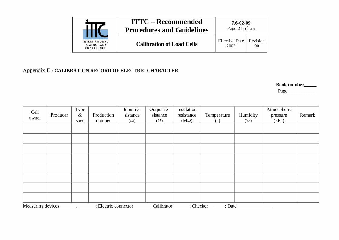
: CALIBRATION RECORD OF ELECTRIC CHARACTER
Book number_____ Page____________
Cell owner Producer
Type &
spec Production
number
Input re-sistance
(Ω)
Output re-sistance
(Ω)
Insulation resistance
(MΩ) Temperature
(°) Humidity
(%)
Atmospheric pressure
(kPa) Remark
Measuring devices_______, _______; Electric connector_______; Calibrator_______; Checker_______; Date_______________
ITTC – Recommended Procedures and Guidelines
7.6-02-09 Page 22 of 25
Calibration of Load Cells Effective Date 2002
Revision 00
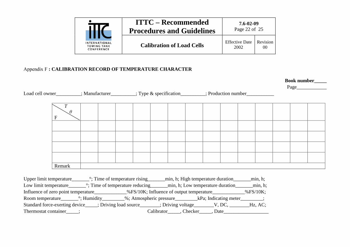
: CALIBRATION RECORD OF TEMPERATURE CHARACTER
Book number_____ Page____________
Load cell owner__________; Manufacturer__________; Type & specification__________; Production number___________
T θ F
Remark
Upper limit temperature_______°; Time of temperature rising_______min, h; High temperature duration_______min, h; Low limit temperature_______°; Time of temperature reducing_______min, h; Low temperature duration_______min, h; Influence of zero point temperature_____________%FS/10K; Influence of output temperature_____________%FS/10K; Room temperature_______°; Humidity_________%; Atmospheric pressure_________kPa; Indicating meter_________; Standard force-exerting device_____; Driving load source________; Driving voltage________V, DC, ________Hz, AC; Thermostat container_____; Calibrator_____, Checker_____, Date__________________

ITTC – Recommended Procedures and Guidelines
7.6-02-09 Page 23 of 25
Calibration of Load Cells Effective Date 2002
Revision 00
: CALIBRATION RECORD OF CREEP
Book number_____ Page____________
Load cell owner_____; Manufacturer______; Type & specification______; Production number______; Temperature______°; Humidity_______%; Atmospheric pressure_______kPa; Driving voltage_______V, DC_______Hz,AC; Preheat_______min, Variation_______V; Preloading_______times, up to_______ft, kgf,N Calibrated items: Cp, Cr ; Register: r= Δt= s, min, h Remark Unit Decade 0 1 2 3 4 5 6 7 8 9
0 1 2 3 4 5 6 7 8
Indicating meter______; Driving load source______; Standard force-exerting device______; Duration of loading ti_______s; Duration of unloading td______s; Stable duration______s; Creep Cp______%FS/30min; Creep recovery Cr______%FS/30min Calibrator________, Checker________, Date______________

ITTC – Recommended Procedures and Guidelines
7.6-02-09 Page 24 of 25
Calibration of Load Cells Effective Date 2002
Revision 00
: CALIBRATION RECORD OF NATURAL FREQUENCY
Book number_____ Page____________
Order number
Unit Manufacturer Type
& spec Production
number Time index (ms/grid)
Amplitude index (V/grid)
Period number
Time (ms)
Natural frequency f0 (Hz)
Remark
Driving load source_____; Driving voltage_____V; Recording device______; Driving method_____; Wave pattern quality____; Temperature_____°; Humidity_____%; Atmospheric pressure______kPa; Calibrator______, Checker______, Date__________

ITTC – Recommended Procedures and Guidelines
7.6-02-09 Page 25 of 25
Calibration of Load Cells Effective Date 2002
Revision 00
: CALIBRATION RECORD OF ZERO DRIFT
Book number_____ Page____________
Load cell owner_____; Manufacturer_____; Type & specification_____; Production number_____; Driving voltage________V, DC, _________Hz, AC; Preheat_________min, Variation_________V
Time Output
(mV, μV)
Temperature
(°)
Humidity
(%)
Atmospheric pressure
(kPa)
Time
Output
(mV, μV)
Temperature
(°)
Humidity
(%)
Atmospheric pressure
(kPa)
Remark
Indicating meter_____; Driving load source_____; Zero drift Zd_____%FS/___h; Temperature____°; Humidity_____%; Atmospheric pressure_____kPa Calibrator________, Checker________, Date____________