its-02-001-202002 delivery specification: variable message
TRANSCRIPT
ITS Specification Variable Message Sign – Fixed
Project Compliance: Mandatory
© Waka Kotahi NZ Transport Agency Published: Effective from: 25/02/2020 Approved by: Russell Pinchen ISBN number (online): Document Status: Draft 3 (Approved Document awaiting ratification) Version number: 0.3
Waka Kotahi NZ Transport Agency Specification – VMS Fixed Approved document awaiting ratification Effective from 25/02/2020
Copyright information
The Waka Kotahi NZ Transport Agency (Waka Kotahi) ITS Standards & Specifications Framework is protected by copyright owned by Waka Kotahi on behalf of the Crown or its licensors. Unless indicated otherwise for specific items or collections of content (either below or within specific items or collections), this copyright material is licensed for re-use under the Creative Commons Attribution 4.0 International licence. You are free to copy, distribute and adapt the material, if you attribute it to Waka Kotahi and abide by the other licence terms.
The permission to reproduce material in this publication does not extend to re-using any logos, emblems and trademarks in the document in other contexts, to the document design elements or material for which the copyright is identified as being held by a third party. Authorisation to reproduce material belonging to a third party must be obtained from the copyright holder(s) concerned.
Disclaimer
Waka Kotahi has endeavoured to ensure material in this document is technically accurate and reflects legal requirements. However, the document does not override governing legislation. Waka Kotahi does not accept liability for any consequences arising from the use of this document. If the user of this document is unsure whether the material is correct, they should refer directly to the relevant legislation and make independent enquiries.
More information
If you have further queries, contact the Standards & Specifications Document Administrator via email: [email protected]
The current version of this document is available on the Waka Kotahi website at http://www.nzta.govt.nz/resources/intelligent-transport-systems/
Page i
Waka Kotahi NZ Transport Agency Specification – VMS Fixed Approved document awaiting ratification Effective from 25/02/2020
Document management plan
1. Purpose The purpose of this document is to specify the minimum requirements for procurement of variable message signs (VMS) by Waka Kotahi. In addition, this specification will detail system integration requirement (eg protocols, interfaces, data standards etc) to ensure compliance with Waka Kotahi systems and standards.
2. Document information
Document name ITS Specification for VMS
Document number ITS-02-001-202002-SPEC-VMS-FIXED
Previous document number/s (if applicable)
ITS-06-01
Document status Draft 3 (Approved Document awaiting ratification)
Document availability This document is in electronic form on the Waka Kotahi ITS website at:
http://www.nzta.govt.nz/resources/intelligent-transport-systems/
Document authors Kirill Yushenko Consultant, Resolve Group
Peter Bathgate Consultant, Resolve Group
Document owner Russell Pinchen (Waka Kotahi)
3. Key words ITS, VMS
Record of amendments (this section is used post-ratification)
Amendment number
Section amended
Description of change Updated by Effective date

Page ii
Waka Kotahi NZ Transport Agency Specification – VMS Fixed Approved document awaiting ratification Effective from 25/02/2020
Record of artefacts for removal from this specification and inclusion in future ITS specifications
This section records any circumstances where a section from this specification will be removed for inclusion in a future ITS specification, where it makes sense to reference this information from more than one specification. For example, generic information about power supply.
PAGE NUMBER
SECTION REFERENCE
FUTURE DOCUMENT CHECKED BY
ACTION
20 l Time Synchronisation – NTP
14 5.1.1 Environmental Conditions Specification
18 6.1 Power Standard
Reference to dependent standards and specifications
Standards and specifications that shall be conformed to in conjunction with this standard or specification. This section records all supporting documents, to assist with reviews and updates.
NAME OF SUPPORTING DOCUMENT REFERENCE
Road vertical signs. Variable message traffic signs EN 12966:2014
Communications protocols Refer to Waka Kotahi
Waka Kotahi ITS specification – General requirements ITS-01-01
Waka Kotahi ITS specification – Handover and commissioning process ITS-10-01
Electromagnetic compatibility – Requirements for household appliances, electric tools and similar apparatus – Emission
AS/NZS CISPR 14.1:2013
Lighting for roads and public spaces; including all supplements of AS/NZS 1158 AS/NZS 1158
Cold-formed structural steel hollow sections AS/NZS 1163:2016
Structural design actions – Permanent, imposed and other actions AS/NZS 1170.1:2002
Structural design actions – Wind actions AS/NZS 1170.2:2011
IP Degree of Protection EN 60529
Coating Standard AS/NZS 2312.1:2014

Page iii
Waka Kotahi NZ Transport Agency Specification – VMS Fixed Approved document awaiting ratification Effective from 25/02/2020
Contents
INTRODUCTION .............................................................................................................. 6
1.1 Strategic context ..................................................................................................................... 6
1.2 Strategic outcomes ................................................................................................................. 6 Outcomes for road users ........................................................................................................... 6
Outcomes for road controlling authorities .................................................................................. 7
1.3 Operational outcomes ............................................................................................................. 7
1.4 In scope ................................................................................................................................... 7
1.5 Out of scope ............................................................................................................................ 7
TERMS AND DEFINITIONS............................................................................................. 8
OPERATIONAL REQUIREMENTS ................................................................................ 10
FUNCTIONAL REQUIREMENTS .................................................................................. 11
4.1 Full colour or monochrome display ....................................................................................... 11
4.2 Display uniformity .................................................................................................................. 11
4.3 Display clarity and visibility ................................................................................................... 11
4.4 Fully operable display ........................................................................................................... 11
4.5 Remote message sources .................................................................................................... 11
4.6 Storage of text and graphics ................................................................................................. 11
4.7 Logging performance parameters including faults ................................................................ 12
4.8 Messages currency (kept up to date) ................................................................................... 12
4.9 Prompt message display ....................................................................................................... 12
4.10 Message queuing and prioritisation .................................................................................. 12
4.11 Handling of fault conditions ............................................................................................... 12
4.12 Compliance with Waka Kotahi protocols and other control interfaces .............................. 12
4.13 Integration with the existing Waka Kotahi traffic management system ............................ 12
PERFORMANCE REQUIREMENTS .............................................................................. 13
5.1 Resistance to the effects of external conditions ................................................................... 13 Mechanical performance requirements ................................................................................... 14
Resistance of electrical / electronic components to the effects of pollution ............................. 14
Page iv
Waka Kotahi NZ Transport Agency Specification – VMS Fixed Approved document awaiting ratification Effective from 25/02/2020
Resistance of discontinuous VMS to surface corrosion ........................................................... 14
Enclosure: ingress protection against water and dust ............................................................. 14
5.2 Visual performance requirements ......................................................................................... 14 Display technology options ...................................................................................................... 14
Key front screen parameters ................................................................................................... 14
LED colour palette ................................................................................................................... 14
Colour ...................................................................................................................................... 15
Luminance ............................................................................................................................... 15
Luminance ratio ....................................................................................................................... 15
Beam width .............................................................................................................................. 15
Uniformity of luminous intensity ............................................................................................... 16
Visible flicker – machine readability ......................................................................................... 16
Design life .............................................................................................................................. 16
Degradation of visual performance ........................................................................................ 16
Pixel pitch .............................................................................................................................. 16
Bezel thickness ...................................................................................................................... 17
TECHNICAL (UNIT) REQUIREMENTS ......................................................................... 18
6.1 Electrical performance requirements .................................................................................... 18 LEDs ........................................................................................................................................ 18
Power supply ........................................................................................................................... 18
Power consumption ................................................................................................................. 18
Nominal voltages ..................................................................................................................... 18
A.C. Operating voltage range .................................................................................................. 19
Mains frequency ...................................................................................................................... 19
Power-up activation ................................................................................................................. 19
Low voltage – switch-off voltage response .............................................................................. 19
Low voltage – voltage interruption ........................................................................................... 19
Low voltage – temporary over-voltage ................................................................................... 19
Electrical safety ..................................................................................................................... 19
Electromagnetic emission and immunity ................................................................................ 19
Electrical surge protection ..................................................................................................... 19
6.2 Systems integration – sign control ........................................................................................ 20 Sign controller .......................................................................................................................... 20
Fault reporting ......................................................................................................................... 20
6.3 Other considerations – physical characteristics .................................................................... 22 Finish ....................................................................................................................................... 22
Front panels ............................................................................................................................. 22
Front screens ........................................................................................................................... 22
Heating and forced ventilation ................................................................................................. 22
Doors and maintenance access .............................................................................................. 22
Vertical alignment .................................................................................................................... 23
Page v
Waka Kotahi NZ Transport Agency Specification – VMS Fixed Approved document awaiting ratification Effective from 25/02/2020
Penetrations ............................................................................................................................ 23
Electrolytic compatibility........................................................................................................... 23
Lifting eyes .............................................................................................................................. 23
Mounting to support structure ................................................................................................ 23
Speed environment and character height .............................................................................. 23
Labelling ................................................................................................................................ 23
Transportation ....................................................................................................................... 23
Pre-award certification ........................................................................................................... 24
Operations and maintenance considerations ......................................................................... 24
General .................................................................................................................................. 24
FAT, SAT and commissioning, spare parts, servicing manuals, warranty, defects liability period 25
Appendix A – Waka Kotahi VMS types ....................................................................................... 26
References ..................................................................................................................................... 27
Page 6
Waka Kotahi NZ Transport Agency Specification – VMS Fixed Approved document awaiting ratification Effective from 25/02/2020
Introduction
The purpose of this document is to specify the minimum requirements for the procurement of variable
message signs (VMS) by Waka Kotahi. In addition, this specification details system integration
requirements (such as protocols, interfaces, data standards etc) to ensure compliance with Waka Kotahi
operational and asset management systems.
The outcomes of the specification are to provide guidance in order to procure high quality, energy efficient
and long-lasting VMS which have a proven track record in a similar operating environment to New Zealand.
Additional requirements to support other applications will be added over time.
The specification does not describe the detailed form and message configuration / limitations of a
VMS; these elements are detailed in the Waka Kotahi VMS standard (under development).
1.1 Strategic context
Waka Kotahi requires tools to disseminate predictive or current information to road users along motorways,
expressways, rural and local roads on traffic conditions or to improve general conditions of network use.
Those tools aim to contribute to improving road safety and user comfort. VMS play an important role for
Waka Kotahi to achieve those goals.
VMS are generally located on motorways, expressways, rural and local roads to provide inter-regional and
tactical messaging capability. This specification shall be applicable to all NZ state highways nationally and
regional roading authorities.
The Waka Kotahi ITS framework is produced for procurement purposes only; it is not a legal instrument
and does not relieve users of legal compliance requirements or regulations.
1.2 Strategic outcomes
By developing this specification, Waka Kotahi is to achieve the following strategic outcomes specifically to
ensure and enhance the Waka Kotahi dynamic, in-trip messaging capability including (but not limited to):
• enhancing road user notification in normal and adverse conditions
• increasing road user awareness of traffic conditions to assist with improved safety, to provide journey options and to reduce congestion
• improving whole-of-life ITS-related costs by supplying quality VMS assets, including reducing the Waka Kotahi environmental footprint through reduced energy consumption
• minimising constraints associated with power and energy requirements to drive assets in rural applications.
Outcomes for road users
VMS are intended to provide a mechanism to advise users of road conditions, route availability and journey
time estimates. The desired outcome is to keep road users well informed at all times and in all weather
conditions, receiving timely information which will help them undertake their journeys safely and efficiently.
VMS infrastructure is used to advise of adverse weather conditions, road closures and detours, and traffic
conditions in real-time, and to warn of advance works or events which may adversely affect road users’
journeys.
Page 7
Waka Kotahi NZ Transport Agency Specification – VMS Fixed Approved document awaiting ratification Effective from 25/02/2020
Outcomes for road controlling authorities
VMS must be effective, reliable and durable as they are deployed in harsh outdoor environments
and exposed to extremes of temperature and weather as required in Performance requirements
(section 5.0). Trouble-free operation for many years is expected (section 5.1) (VMS are tools that
enable road controlling authorities (RCAs) to actively manage incidents and roadworks.
1.3 Operational outcomes
The intended operational outcomes of this Waka Kotahi specification are to:
• increase road user acceptance of the information by improving the quality of information and images on VMS in normal and adverse conditions
• improve quality of transport operations centres’ (TOCs’) operational activities around VMS (VMS status condition and fault logging)
• minimise maintenance costs
• improve renewal cycles.
1.4 In scope
This document specifies procurement requirements for fixed VMS:
Sign Types Motorway /
Expressway Regional Types A to D
Urban Type D
(EJT) Large Type D
1.5 Out of scope
This specification applies only to standard dimension, fixed location, ‘discontinuous’ VMS, ie those on which
messages can be created because the finest individual elements (pixels) can be in multiple states (off or
any available colour).
Continuous signs which are similar to fixed signs, are not covered by this specification. Note that the only
difference between a fixed sign and a continuous VMS is the ability of the latter to show messages by some
electro and/or mechanical means, eg rotating prisms.
This document does not cover any other form of electronic roadside signage such as relocatable (mobile)
VMS, lane control signals, school zone signs, speed-activated warning signs and advance warning signs
(regional intersection or ramp signal types A and B).
VMS types used exclusively by territorial local authorities are outside the scope of this specification.
Design and installation of fixed VMS sites is covered in the VMS standard (under development).
Page 8
Waka Kotahi NZ Transport Agency Specification – VMS Fixed Approved document awaiting ratification Effective from 25/02/2020
Terms and definitions
TERM DEFINITION
API Application programming interface
Bezel Border surrounding the VMS front screen
Cantilever support Support system with a single post and a cantilever arm supporting the VMS over the traffic lane(s)
CCM Code compliance met
Cd Candela
CIE Commission Internationale de L’Eclairage (International Commission on Illumination)
CMS Changeable message sign
Continuous VMS Show sign faces of the types on fixed signs as defined in EN 12899-1:2007. VMS use electro and/or mechanical means to change between sign faces
Control device Equipment used to execute a change of message other than by purely manual means
Discontinuous VMS Create messages using discontinuous individual elements that can be in one of two states (or more) and can thereby create messages on the same sign face
Display surface Visible part of a VMS that contains the elements that may be activated to display the message.
EJT Estimated journey time
Element Basic visual light emitting [and/or reflecting object or cluster of objects] in the display surface of a VMS, activated in conjunction with other elements to form the desired message. Note: words in purple are generic but outside the scope of this specification
Enclosure The housing for the display and the electronics systems immediately associated with the display
External sources VMS are typically monitored and controlled from transport operations centres (TOCs), however this is not universally applicable. VMS must be able to be controlled (with permission) from multiple remote sources
FAT Factory acceptance test
Front screen Screen protecting the display surface or the parts of it against dust, water etc. Note: front screens are not compliant with this specification
Gantry Support system spanning a carriageway with at least one post either side of the carriageway supporting VMS mounted over the traffic lane(s)
GSM Global System for Mobile Communications
IP International Protection Marking (sometimes interpreted as Ingress Protection) classifies the degree of protection provided by mechanical casings and electrical enclosures against intrusion, dust, accidental contact and water [EN 60529]
ITS Intelligent transport systems
Lantern Multiple LEDs grouped uniformly in a circular array
La Luminance with the VMS turned on
Lb Luminance with the VMS turned off
LED Light emitting diode
LoS Level of service
LR Luminance ratio
MAC Media access control
Page 9
Waka Kotahi NZ Transport Agency Specification – VMS Fixed Approved document awaiting ratification Effective from 25/02/2020
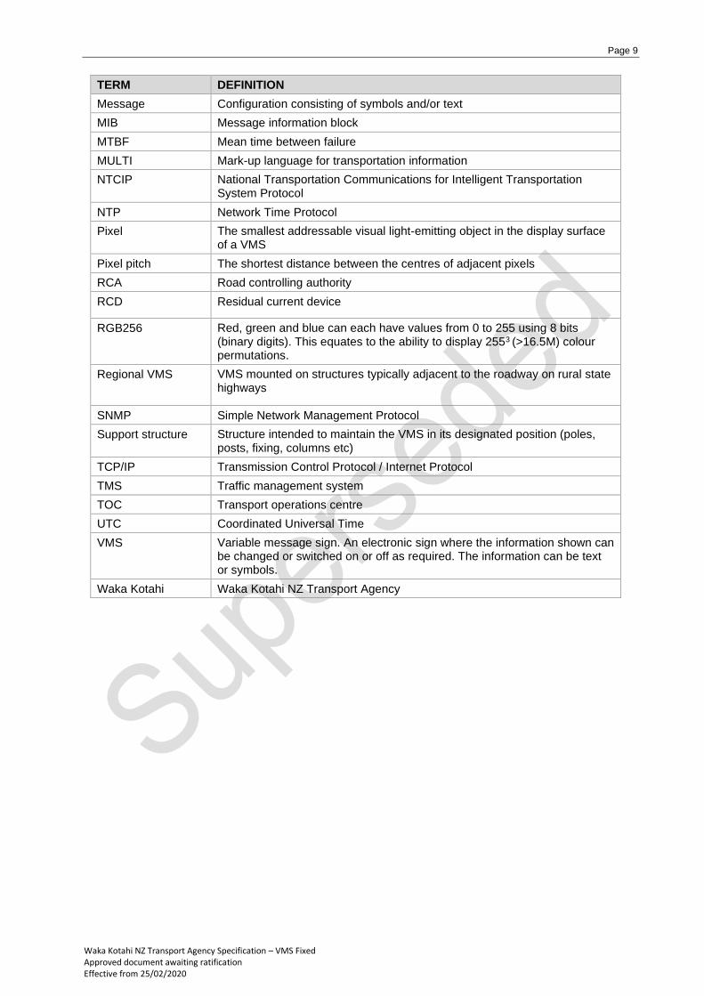
TERM DEFINITION
Message Configuration consisting of symbols and/or text
MIB Message information block
MTBF Mean time between failure
MULTI Mark-up language for transportation information
NTCIP National Transportation Communications for Intelligent Transportation System Protocol
NTP Network Time Protocol
Pixel The smallest addressable visual light-emitting object in the display surface of a VMS
Pixel pitch The shortest distance between the centres of adjacent pixels
RCA Road controlling authority
RCD Residual current device
RGB256 Red, green and blue can each have values from 0 to 255 using 8 bits (binary digits). This equates to the ability to display 2553 (>16.5M) colour permutations.
Regional VMS VMS mounted on structures typically adjacent to the roadway on rural state highways
SNMP Simple Network Management Protocol
Support structure Structure intended to maintain the VMS in its designated position (poles, posts, fixing, columns etc)
TCP/IP Transmission Control Protocol / Internet Protocol
TMS Traffic management system
TOC Transport operations centre
UTC Coordinated Universal Time
VMS Variable message sign. An electronic sign where the information shown can be changed or switched on or off as required. The information can be text or symbols.
Waka Kotahi Waka Kotahi NZ Transport Agency
Page 10
Waka Kotahi NZ Transport Agency Specification – VMS Fixed Approved document awaiting ratification Effective from 25/02/2020
Operational requirements
This specification for VMS contributes to the Waka Kotahi strategic fit, operational services, safety,
efficiency and value for money.
VMS must provide a guaranteed delivery LoS (that is a mechanism to communicate to road users by the
nature of VMS being positioned adjacent to, or above, traffic lanes) for messaging Waka Kotahi users.
These are the requirements. The VMS must:
• be able to display highly visible and legible messages to road users under all conditions
• be positioned in locations which maximise visibility both optically (optimising height and viewing angles)
and logically (preceding important journey decision points). These aspects are covered in the Waka
Kotahi VMS standard (under development)
• not constrain ability to deliver required messages (noting message configuration will change with
operations requirements)
• provide operational status feedback to confirm that VMS are displaying the required message.
Page 11
Waka Kotahi NZ Transport Agency Specification – VMS Fixed Approved document awaiting ratification Effective from 25/02/2020
Functional requirements
This section describes the high-level functions that VMS must perform
4.1 Full colour or monochrome display
Full-colour VMS must be able to display text and graphics as defined in section 5.2.3. Monochrome VMS
must display yellow colour as defined in section 5.2.4.
4.2 Display uniformity
The display of the VMS must appear to be uniform and consistent.
Physically the display must be formed using a regular matrix, that is the spacing between individual light
sources in both the x and y axes is uniform. Optically there should be no visible variation in the colour of
the light produced and display luminance (‘brightness’) should not vary across the display.
4.3 Display clarity and visibility
The display of the VMS must be clearly legible and highly visible throughout the required viewing range
and be appropriate in all environmental conditions.
Automatic brightness control must ensure that the intensity of the display aligns with ambient lighting
conditions.
The contrast ratio must ensure that all images displayed on the VMS are clearly legible under all conditions.
4.4 Fully operable display
The display must be fully operable, that is each individual display element (pixel) must be able to be
controlled separately; in effect, the VMS is yellow monochrome or full colour (as required) and fully graphics
capable – it is not constrained to use alphanumeric characters arrayed across a fixed number of lines.
Appendix A notes the minimum message display dimensions required by Waka Kotahi.
4.5 Remote message sources
The VMS must be able to be commanded to display messages received from approved external sources
(such as TOCs or hosted applications).
The VMS must be able to communicate status including faults, confirm receipt and read-back messages,
and communicate any required performance parameters to the approved external source(s).
4.6 Storage of text and graphics
The VMS must be able to display alphanumeric messages and graphics from an on-board library which
can be commanded without sending the full content of the message. For example, a complex message
could be stored with the label ‘Message1’; receiving a properly formatted request to display Message1
would display the complex message.

Page 12
Waka Kotahi NZ Transport Agency Specification – VMS Fixed Approved document awaiting ratification Effective from 25/02/2020
4.7 Logging performance parameters including faults
The VMS must maintain logs and retain performance parameters including fault conditions until retrieved
for resolution.
4.8 Messages currency (kept up to date)
The VMS must ensure that messages are kept up to date by maintaining regular contact with the message
source. It must take agreed appropriate action(s) as defined in section 6.1.2 m (typically blanking the
screen) if regular communication is lost.
4.9 Prompt message display
The VMS must ensure that the time difference between receipt and display of a message is compliant with
Performance requirements (section 5.0).
4.10 Message queuing and prioritisation
The VMS must be able to prioritise incoming messages based on the priority of the message received and
the hierarchy of the message source using NTCIP (v3 or latest) parameters for contention. Incoming
messages must be stored, queued hierarchically pending display.
Message prioritisation (contention) is based solely on NTCIP parameters and must be independent of the
physical ports on which messages are received.
4.11 Handling of fault conditions
The VMS must take appropriate action when faults arise. Under no circumstances can the VMS display to
road users:
• brightness levels which are inconsistent with ambient lighting or are not uniform across the display
• partial, incomplete or otherwise potentially unintelligible messages.
4.12 Compliance with Waka Kotahi protocols and other control interfaces
The VMS must be configured to comply with prevailing Waka Kotahi protocols, and other control interfaces
as specifically requested in the procurement documentation.
4.13 Integration with the existing Waka Kotahi traffic management system
VMS procured using this specification must be able to interface seamlessly with the current Waka Kotahi
national traffic management system.
Page 13
Waka Kotahi NZ Transport Agency Specification – VMS Fixed Approved document awaiting ratification Effective from 25/02/2020
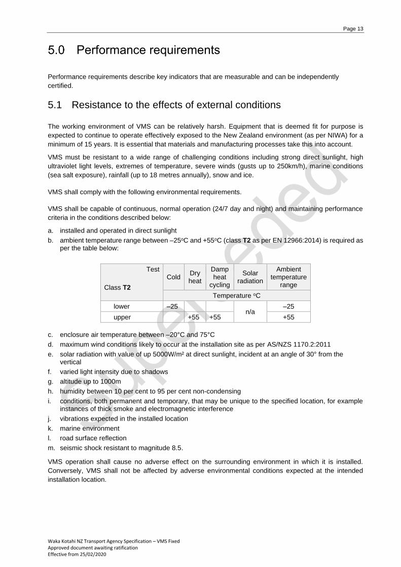
Performance requirements
Performance requirements describe key indicators that are measurable and can be independently
certified.
5.1 Resistance to the effects of external conditions
The working environment of VMS can be relatively harsh. Equipment that is deemed fit for purpose is
expected to continue to operate effectively exposed to the New Zealand environment (as per NIWA) for a
minimum of 15 years. It is essential that materials and manufacturing processes take this into account.
VMS must be resistant to a wide range of challenging conditions including strong direct sunlight, high
ultraviolet light levels, extremes of temperature, severe winds (gusts up to 250km/h), marine conditions
(sea salt exposure), rainfall (up to 18 metres annually), snow and ice.
VMS shall comply with the following environmental requirements.
VMS shall be capable of continuous, normal operation (24/7 day and night) and maintaining performance
criteria in the conditions described below:
a. installed and operated in direct sunlight
b. ambient temperature range between –25oC and +55oC (class T2 as per EN 12966:2014) is required as per the table below:
Test
Class T2
Cold Dry heat
Damp heat
cycling
Solar radiation
Ambient temperature
range
Temperature oC
lower –25 n/a
–25
upper +55 +55 +55
c. enclosure air temperature between –20°C and 75°C
d. maximum wind conditions likely to occur at the installation site as per AS/NZS 1170.2:2011
e. solar radiation with value of up 5000W/m² at direct sunlight, incident at an angle of 30° from the vertical
f. varied light intensity due to shadows
g. altitude up to 1000m
h. humidity between 10 per cent to 95 per cent non-condensing
i. conditions, both permanent and temporary, that may be unique to the specified location, for example instances of thick smoke and electromagnetic interference
j. vibrations expected in the installed location
k. marine environment
l. road surface reflection
m. seismic shock resistant to magnitude 8.5.
VMS operation shall cause no adverse effect on the surrounding environment in which it is installed.
Conversely, VMS shall not be affected by adverse environmental conditions expected at the intended
installation location.

Page 14
Waka Kotahi NZ Transport Agency Specification – VMS Fixed Approved document awaiting ratification Effective from 25/02/2020
Mechanical performance requirements
VMS shall be designed to ensure reliable transfer of all static and dynamic forces to the fixing and mounting
structures.
VMS must meet class WL9 as per EN 12966:2014 for wind loading, class DSL4 as per EN 12966:2014 for
dynamic snow loading, class TBD6 as per EN 12966:2014 for temporary bending deflection. See section
4.5.2.5 of EN 12966:2014 for details of mechanical performance requirements.
Resistance of electrical / electronic components to the effects of pollution
The manufacturer shall declare the degree of resistance in accordance section 4.5.2.2 of EN 12966:2014.
Resistance of discontinuous VMS to surface corrosion
The surface protection of VMS enclosures against corrosion shall be class SP2 as per EN 12966:2014 and meet requirements of section 4.5.2.3 of EN 12966:2014.
Enclosure: ingress protection against water and dust
VMS enclosures shall be protected against water and dust ingress in accordance with section 4.5.2.4 of
EN 12966:2014. All VMS enclosures must meet a minimum IP rating of IP56 (P3 as per EN 12966:2014).
5.2 Visual performance requirements
Display technology options
For all VMS applications, Waka Kotahi has selected LED technologies as the default choice for the displays.
This technology provides good visibility under most viewing conditions, high reliability and low optical
degradation, and has low maintenance requirements.
Key front screen parameters
The VMS display must consist of a full matrix and be capable of displaying a single steady screen and
two alternating screens depending on message length.
Although not traditionally defined under visual performance requirements, the key front screen parameters
which must be specified are:
Parameter Display area (height x width) Pixel pitch
(uniform horizontal
and vertical matrix) Bezel thickness
Specified in Appendix for different VMS types
(based on road operating speed, location) See sections 5.2.12 and 5.2.13
LED colour palette
When observing the whole VMS front screen from all viewing angles within the specified beam width,
colours shall not be discernible as individual red, green and blue light sources.
Each individual red, green and blue LED must be capable of displaying 256 shades of corresponding colours equating to 256 x 256 x 256 colour permutations (>16 million colours).
Page 15
Waka Kotahi NZ Transport Agency Specification – VMS Fixed Approved document awaiting ratification Effective from 25/02/2020
Colour
All VMS must meet colour class C2 as per EN 12966:2014.
The chromaticity coordinates of the required colour parameters are defined in table 3 and figure 1 of section
4.4.2 of EN 12966:2014.
Luminance
La is the luminance with the VMS turned on; the VMS must achieve the minimum stated value La(min).
Luminance values must not exceed La(max) with external illumination (solar simulator) turned on.
All VMS must meet luminance levels to class L3 as per table 4 to table 9 of section 4.4.3 of EN 12966:2014.
Luminance ratio
All VMS must meet luminance ratio class R3 as per table 10 of section 4.4.4 of EN 12966:2014.
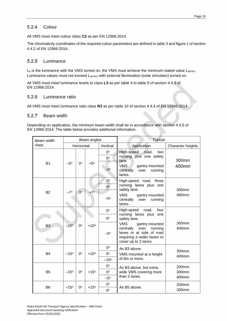
Beam width
Depending on application, the minimum beam width shall be in accordance with section 4.4.5 of EN 12966:2014. The table below provides additional information.
Beam width class
Beam angles Typical
Horizontal Vertical Application Character heights
B1 –5o 0o +5o
0o High-speed road, two running plus one safety lane.
VMS gantry-mounted centrally over running lanes.
300mm
400mm
0o
–5o
B2 –7o 0o +7o
0o High-speed road, three running lanes plus one safety lane.
VMS gantry-mounted centrally over running lanes.
300mm
400mm
0o
–5o
B3 –10o 0o +10o
0o High-speed road, four running lanes plus one safety lane.
VMS gantry-mounted centrally over running lanes or at side of road requiring a wider beam to cover up to 2 lanes.
300mm
400mm
0o
–5o
B4 –10o 0o +10o
0o As B3 above.
VMS mounted at a height of 6m or more.
300mm
400mm 0o
–10o
B5 –15o 0o +15o
0o As B3 above, but extra-wide VMS covering more than 2 lanes.
200mm
300mm
400mm
0o
–5o
B6 –15o 0o +15o 0o
As B5 above. 200mm
300mm 0o
Page 16
Waka Kotahi NZ Transport Agency Specification – VMS Fixed Approved document awaiting ratification Effective from 25/02/2020
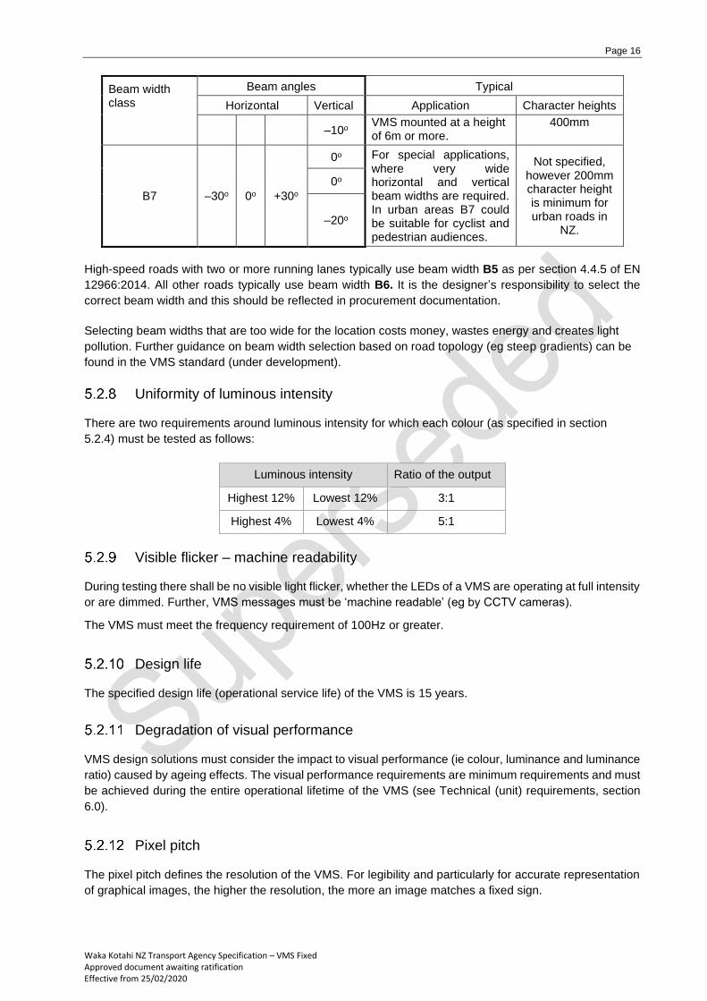
Beam width class
Beam angles Typical
Horizontal Vertical Application Character heights
–10o VMS mounted at a height of 6m or more.
400mm
B7 –30o 0o +30o
0o For special applications, where very wide horizontal and vertical beam widths are required. In urban areas B7 could be suitable for cyclist and pedestrian audiences.
Not specified, however 200mm character height is minimum for urban roads in
NZ.
0o
–20o
High-speed roads with two or more running lanes typically use beam width B5 as per section 4.4.5 of EN
12966:2014. All other roads typically use beam width B6. It is the designer’s responsibility to select the
correct beam width and this should be reflected in procurement documentation.
Selecting beam widths that are too wide for the location costs money, wastes energy and creates light
pollution. Further guidance on beam width selection based on road topology (eg steep gradients) can be
found in the VMS standard (under development).
Uniformity of luminous intensity
There are two requirements around luminous intensity for which each colour (as specified in section
5.2.4) must be tested as follows:
Luminous intensity Ratio of the output
Highest 12% Lowest 12% 3:1
Highest 4% Lowest 4% 5:1
Visible flicker – machine readability
During testing there shall be no visible light flicker, whether the LEDs of a VMS are operating at full intensity
or are dimmed. Further, VMS messages must be ‘machine readable’ (eg by CCTV cameras).
The VMS must meet the frequency requirement of 100Hz or greater.
Design life
The specified design life (operational service life) of the VMS is 15 years.
Degradation of visual performance
VMS design solutions must consider the impact to visual performance (ie colour, luminance and luminance
ratio) caused by ageing effects. The visual performance requirements are minimum requirements and must
be achieved during the entire operational lifetime of the VMS (see Technical (unit) requirements, section
6.0).
Pixel pitch
The pixel pitch defines the resolution of the VMS. For legibility and particularly for accurate representation
of graphical images, the higher the resolution, the more an image matches a fixed sign.
Page 17
Waka Kotahi NZ Transport Agency Specification – VMS Fixed Approved document awaiting ratification Effective from 25/02/2020
On large VMS installed above or alongside state highways, the maximum pixel pitch must be 20mm. For
smaller VMS used on local roads, the maximum pixel pitch must be 16mm.
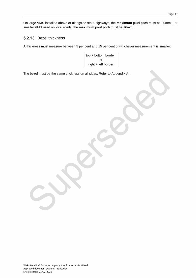
Bezel thickness
A thickness must measure between 5 per cent and 15 per cent of whichever measurement is smaller:
top + bottom border
or
right + left border
The bezel must be the same thickness on all sides. Refer to Appendix A.
Page 18
Waka Kotahi NZ Transport Agency Specification – VMS Fixed Approved document awaiting ratification Effective from 25/02/2020
Technical (unit) requirements
6.1 Electrical performance requirements
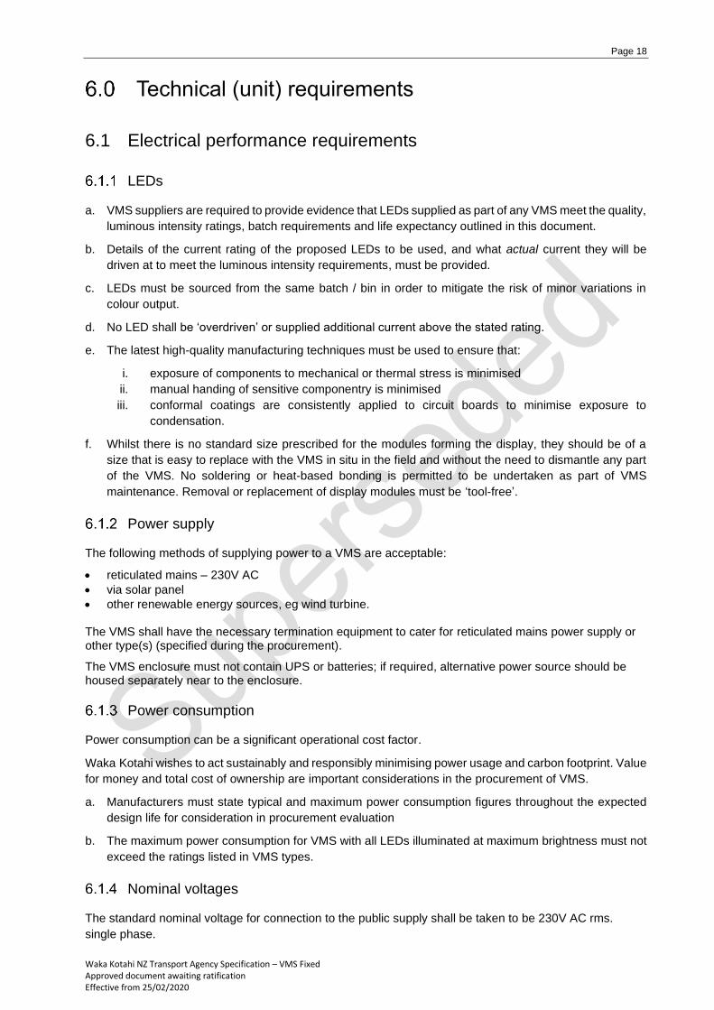
LEDs
a. VMS suppliers are required to provide evidence that LEDs supplied as part of any VMS meet the quality,
luminous intensity ratings, batch requirements and life expectancy outlined in this document.
b. Details of the current rating of the proposed LEDs to be used, and what actual current they will be
driven at to meet the luminous intensity requirements, must be provided.
c. LEDs must be sourced from the same batch / bin in order to mitigate the risk of minor variations in
colour output.
d. No LED shall be ‘overdriven’ or supplied additional current above the stated rating.
e. The latest high-quality manufacturing techniques must be used to ensure that:
i. exposure of components to mechanical or thermal stress is minimised
ii. manual handing of sensitive componentry is minimised
iii. conformal coatings are consistently applied to circuit boards to minimise exposure to
condensation.
f. Whilst there is no standard size prescribed for the modules forming the display, they should be of a
size that is easy to replace with the VMS in situ in the field and without the need to dismantle any part
of the VMS. No soldering or heat-based bonding is permitted to be undertaken as part of VMS
maintenance. Removal or replacement of display modules must be ‘tool-free’.
Power supply
The following methods of supplying power to a VMS are acceptable:
• reticulated mains – 230V AC
• via solar panel
• other renewable energy sources, eg wind turbine.
The VMS shall have the necessary termination equipment to cater for reticulated mains power supply or other type(s) (specified during the procurement).
The VMS enclosure must not contain UPS or batteries; if required, alternative power source should be housed separately near to the enclosure.
Power consumption
Power consumption can be a significant operational cost factor.
Waka Kotahi wishes to act sustainably and responsibly minimising power usage and carbon footprint. Value
for money and total cost of ownership are important considerations in the procurement of VMS.
a. Manufacturers must state typical and maximum power consumption figures throughout the expected
design life for consideration in procurement evaluation
b. The maximum power consumption for VMS with all LEDs illuminated at maximum brightness must not
exceed the ratings listed in VMS types.
Nominal voltages
The standard nominal voltage for connection to the public supply shall be taken to be 230V AC rms.
single phase.

Page 19
Waka Kotahi NZ Transport Agency Specification – VMS Fixed Approved document awaiting ratification Effective from 25/02/2020
A.C. Operating voltage range
Variations in the nominal supply voltage defined in section 4.5.3.1.3 of EN 12966:2014 shall not affect the
VMS functions. This shall be tested in accordance with table 16 and table 17 of EN 12966:2014 and shall
meet the requirements given therein.
Mains frequency
Variations within the frequency range of 50 ± 1 Hz shall not affect the VMS functions.
Power-up activation
The VMS shall be ready for activation when the supply voltage reaches a value within its operating voltage
range. At no time during power-up activation shall partial, incomplete or false messages be displayed.
Low voltage – switch-off voltage response
A drop in the nominal voltage of more than 13 per cent shall not cause partial, incomplete or false messages
to be displayed or cause damage to the VMS.
Low voltage – voltage interruption
The effect of voltage interruption shall be as per section 4.5.3.1.6.2 of EN 12966:2014.
Low voltage – temporary over-voltage
When protection for temporary (not transient) over voltage is incorporated, the operating voltage range of
the protective device shall be stated and shall be tested in accordance with table 16 of EN 12966:2014 and
shall meet the requirements given therein.
Electrical safety
VMS shall conform to the latest Australian/New Zealand Wiring Rules, AS/NZS 3000 and to applicable
European standards for internal componentry (which does not have external connection to the mains
supply) as per section 4.5.3.2 of EN 12966:2014.
All serviceable components should be secured with fastening made from non-conductive materials.
The VMS enclosure must not have any exposed electrical contacts.
Electromagnetic emission and immunity
For all types of environment, the VMS shall conform to EN 50293:2012.
The performance of any external equipment must not be interrupted by any radio frequency or electromagnetic interference generated by the VMS or vice versa.
Electrical surge protection
All display equipment shall be internally protected against damage resulting from:
• lightning strikes near the VMS or gantry
• electrical transients on power cabling
• electrical transients on internal and external signal wiring
Page 20
Waka Kotahi NZ Transport Agency Specification – VMS Fixed Approved document awaiting ratification Effective from 25/02/2020
• electromagnetic interference
• static electrical discharge.
Surge protection shall be provided on the incoming power circuits and communications circuits.
6.2 Systems integration – sign control
Sign controller
1. The sign controller must be able to operate the VMS in both local-control mode (ie no external
communications) and remote-control mode (ie communicating with an external central control system).
2. The embedded controller must support a fully featured, industry standard, embedded operating system.
3. The embedded controller must be able to support various industry standard protocols such as
RS485/RS422, Ethernet IP and WLAN.
4. The controller must support NTCIP (NTCIP 1203 for Dynamic Message Signs) including MULTI and,
as a minimum, support the elements defined in the NZ VMS MIB v3.
5. The controller must comply with Waka Kotahi or local authority (if applicable) security requirements.
The controller must be able to:
a. send, receive and interpret SNMP commands over TCP/IP protocol to/from the Waka Kotahi central
control system
b. control the display of messages on the VMS
c. retain fault logs locally until retrieved by the Waka Kotahi authorised asset manager or logging
system
d. report VMS fault conditions to the central control system as soon as the communication network is
available
e. receive direct manual instruction from vendor proprietary software (local or remote)
f. store 150 text-based messages or graphic images for immediate display
g. have sufficient RAM memory to upload and download messages as defined above
h. incorporate a watchdog timer to detect out-of-program conditions and reset the controller
i. automatically blank which immediately clears the message in the event of internal or external critical
failures such as a communications failure
j. provide an interface for a laptop computer running Microsoft Windows operating system for
configuration, uploading and downloading messages, and diagnostic testing
k. in local mode, support operator selection of dimming level, pre-stored messages, and diagnostic
routines capable of testing full VMS operation
l. display the message within an elapsed time of less than one second of receiving the command
m. support time synchronisation from an external clock, eg UTC, NTP.
Fault reporting
The sign controller must monitor the operation and health of the VMS and communicate status with the
control room. Alerts on the Operators’ workstation indicate whenever a problem occurs, which will prevent
correct display of messages on the VMS.
Page 21
Waka Kotahi NZ Transport Agency Specification – VMS Fixed Approved document awaiting ratification Effective from 25/02/2020
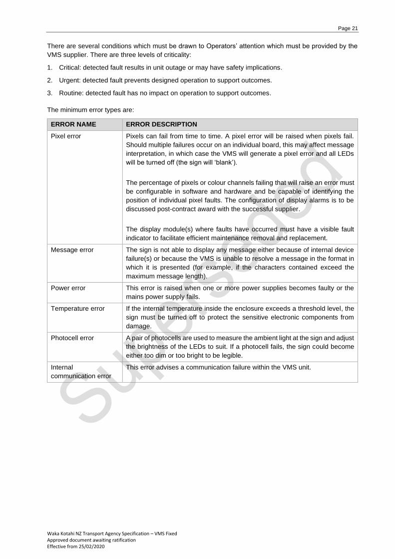
There are several conditions which must be drawn to Operators’ attention which must be provided by the
VMS supplier. There are three levels of criticality:
1. Critical: detected fault results in unit outage or may have safety implications.
2. Urgent: detected fault prevents designed operation to support outcomes.
3. Routine: detected fault has no impact on operation to support outcomes.
The minimum error types are:
ERROR NAME ERROR DESCRIPTION
Pixel error Pixels can fail from time to time. A pixel error will be raised when pixels fail.
Should multiple failures occur on an individual board, this may affect message
interpretation, in which case the VMS will generate a pixel error and all LEDs
will be turned off (the sign will ‘blank’).
The percentage of pixels or colour channels failing that will raise an error must
be configurable in software and hardware and be capable of identifying the
position of individual pixel faults. The configuration of display alarms is to be
discussed post-contract award with the successful supplier.
The display module(s) where faults have occurred must have a visible fault
indicator to facilitate efficient maintenance removal and replacement.
Message error The sign is not able to display any message either because of internal device
failure(s) or because the VMS is unable to resolve a message in the format in
which it is presented (for example, if the characters contained exceed the
maximum message length).
Power error This error is raised when one or more power supplies becomes faulty or the
mains power supply fails.
Temperature error If the internal temperature inside the enclosure exceeds a threshold level, the
sign must be turned off to protect the sensitive electronic components from
damage.
Photocell error A pair of photocells are used to measure the ambient light at the sign and adjust
the brightness of the LEDs to suit. If a photocell fails, the sign could become
either too dim or too bright to be legible.
Internal
communication error
This error advises a communication failure within the VMS unit.

Page 22
Waka Kotahi NZ Transport Agency Specification – VMS Fixed Approved document awaiting ratification Effective from 25/02/2020
6.3 Other considerations – physical characteristics
Finish
The finish of all VMS surfaces should not result in specular (mirror) reflection that distracts road users. The
use of smooth, monolithic front screens (such as polycarbonate panels) is not permitted.
The enclosure is to be aluminium or aluminium alloy with powder-coated finish.
The colour of the enclosure coating is to be matt black at the front and aircraft grey (BS381 693) on other
surfaces.
The coating must facilitate the removal of graffiti.
Front panels
VMS front panels should be designed in such a way that no part of the message displayed is obscured
when observed from the required viewing positions. They should be designed in such a way as to minimise
the effects of ice and snow.
Front screens
Front screens adversely impact the intensity of light being transmitted from the VMS and can be prone to
degradation caused by weathering and exposure to intense direct sunlight. Consequently, monolithic
screens such as polycarbonate panels are not permitted.
VMS which allow portions of the front screen to be removed (‘modular’) may risk weather tightness of the
enclosure and are not permitted.
Heating and forced ventilation
The provision of heaters and fans for supplementary environmental control within the enclosure is not
permitted.
Doors and maintenance access
1. Must include physical security against unauthorised access.
2. All covers, doors, protective screens, plates, glands, external connectors etc shall be provided with
rubber seals or equivalent materials which are maintenance free and shall remain effective for the
design life of the equipment.
3. Where access doors are provided, they shall be fitted with a suitable retention ‘stay’ to hold the door in
the open position for the safety of maintenance personnel working inside the enclosure. For security,
access doors and panels shall be fitted with suitable locks (one lock per door / panel), designed for
outside conditions. Unless specified otherwise, all access door locks shall have an identical key, and
the supplier shall provide at least four copies of the key.
4. For regional VMS the enclosure is located approximately 3 metres above the ground. The design
should ensure ease of access to components for ladder-based access or facilitate the use of portable
access equipment (eg scissor lift or cherry picker).
Page 23
Waka Kotahi NZ Transport Agency Specification – VMS Fixed Approved document awaiting ratification Effective from 25/02/2020
Vertical alignment
Guidance on how the VMS is positioned in relation to the roadway is covered separately in the VMS
standard.
The VMS shall not be fitted with louvres to shade or otherwise direct light emanating or directed onto the
VMS.
Penetrations
All power supply, control and communication cabling shall enter the VMS enclosure through appropriately
constructed, sealed and glanded entry holes. The location of the entry points is specified on design
drawings approved by Waka Kotahi.
Electrolytic compatibility
Components shall comprise materials that when assembled into the VMS are electrolytically compatible
and environmentally stable.
Lifting eyes
The enclosure shall be provided with at least two lifting eyes which enable the VMS to remain horizontal
when lifting the enclosure onto the support structure. The lifting eyes shall be appropriately located ensuring
sufficient structural strength to allow the VMS to be lifted or moved without causing any damage or
deformation to any part of the VMS.
Mounting to support structure
The VMS must be designed to be mounted to the structure on which it will be supported. Modifications to
the VMS enclosure are not permitted once it has left the place of manufacture. The VMS enclosure must
be attached only at the points agreed in the design. Penetration through the enclosure for mounting is not
permitted. Captive nuts in the VMS must be used to attach the structure to the VMS with appropriately sized
fixings (bolts or screws).
Speed environment and character height
Guidance for VMS dimensions and site layout commensurate with operating speed environment are
provided in the VMS standard.
Labelling
All LED display modules shall have unique serial numbers permanently marked, which cannot be removed and shall not ever be modified.
Transportation
VMS should be shipped in containers that protect their contents from damage in transit including extreme temperature, humidity, impact/shock etc. The units must be wrapped to prevent contamination and the packaging should be fitted with a device to indicate whether the unit has been subjected to rough treatment during its journey.
Page 24
Waka Kotahi NZ Transport Agency Specification – VMS Fixed Approved document awaiting ratification Effective from 25/02/2020
Pre-award certification
All VMS supplied to Waka Kotahi must include a declaration of conformity from the manufacturer and
certification from an accredited independent testing facility demonstrating compliance with
EN 12966: 2014. The supplier must provide supplementary report information from the testing facility stating
the LED colour(s), pixel pitch, beam width, luminance, luminance ratio and IP rating of the specific VMS
type being supplied under the Waka Kotahi contract.
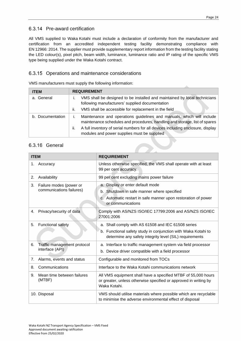
Operations and maintenance considerations
VMS manufacturers must supply the following information:
ITEM REQUIREMENT
a. General i. VMS shall be designed to be installed and maintained by local technicians
following manufacturers’ supplied documentation
ii. VMS shall be accessible for replacement in the field
b. Documentation i. Maintenance and operations guidelines and manuals, which will include
maintenance schedules and procedures, handling and storage, list of spares
ii. A full inventory of serial numbers for all devices including enclosure, display
modules and power supplies must be supplied
General
ITEM REQUIREMENT
1. Accuracy Unless otherwise specified, the VMS shall operate with at least
99 per cent accuracy.
2. Availability 99 per cent excluding mains power failure
3. Failure modes (power or communications failures)
a. Display or enter default mode
b. Shutdown in safe manner where specified
c. Automatic restart in safe manner upon restoration of power
or communications
4. Privacy/security of data Comply with AS/NZS ISO/IEC 17799:2006 and AS/NZS ISO/IEC
27001:2006
5. Functional safety a. Shall comply with AS 61508 and IEC 61508 series
b. Functional safety study in conjunction with Waka Kotahi to
determine any safety integrity level (SIL) requirements
6. Traffic management protocol interface (API)
a. Interface to traffic management system via field processor
b. Device driver compatible with a field processor
7. Alarms, events and status Configurable and monitored from TOCs
8. Communications Interface to the Waka Kotahi communications network
9. Mean time between failures (MTBF)
All VMS equipment shall have a specified MTBF of 55,000 hours
or greater, unless otherwise specified or approved in writing by
Waka Kotahi.
10. Disposal VMS should utilise materials where possible which are recyclable
to minimise the adverse environmental effect of disposal
Page 25
Waka Kotahi NZ Transport Agency Specification – VMS Fixed Approved document awaiting ratification Effective from 25/02/2020
FAT, SAT and commissioning, spare parts, servicing manuals, warranty, defects liability period
Spare parts must be available seven years after sign manufacture is discontinued.
Further requirements including (but not limited to) factory and site acceptance testing, spare parts inventory,
service manuals, warranty, defects liability period and terms of payment must be specified Waka Kotahi in
the procurement of VMS but are outside the scope of this specification. The VMS standard provides advice
on many of these aspects.
Page 26
Waka Kotahi NZ Transport Agency Specification – VMS Fixed Approved document awaiting ratification Effective from 25/02/2020
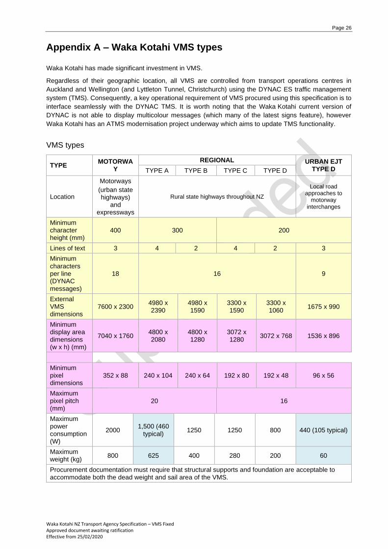
Appendix A – Waka Kotahi VMS types
Waka Kotahi has made significant investment in VMS.
Regardless of their geographic location, all VMS are controlled from transport operations centres in
Auckland and Wellington (and Lyttleton Tunnel, Christchurch) using the DYNAC ES traffic management
system (TMS). Consequently, a key operational requirement of VMS procured using this specification is to
interface seamlessly with the DYNAC TMS. It is worth noting that the Waka Kotahi current version of
DYNAC is not able to display multicolour messages (which many of the latest signs feature), however
Waka Kotahi has an ATMS modernisation project underway which aims to update TMS functionality.
VMS types
TYPE MOTORWA
Y
REGIONAL URBAN EJT TYPE D TYPE A TYPE B TYPE C TYPE D
Location
Motorways
(urban state highways)
and expressways
Rural state highways throughout NZ
Local road approaches to
motorway interchanges
Minimum character height (mm)
400 300 200
Lines of text 3 4 2 4 2 3
Minimum characters per line (DYNAC messages)
18 16 9
External VMS dimensions
7600 x 2300 4980 x 2390
4980 x 1590
3300 x 1590
3300 x 1060
1675 x 990
Minimum display area dimensions (w x h) (mm)
7040 x 1760 4800 x 2080
4800 x 1280
3072 x 1280
3072 x 768 1536 x 896
Minimum pixel dimensions
352 x 88 240 x 104 240 x 64 192 x 80 192 x 48 96 x 56
Maximum pixel pitch (mm)
20 16
Maximum power consumption (W)
2000 1,500 (460
typical) 1250 1250 800 440 (105 typical)
Maximum weight (kg)
800 625 400 280 200 60
Procurement documentation must require that structural supports and foundation are acceptable to accommodate both the dead weight and sail area of the VMS.
Page 27
Waka Kotahi NZ Transport Agency Specification – VMS Fixed Approved document awaiting ratification Effective from 25/02/2020
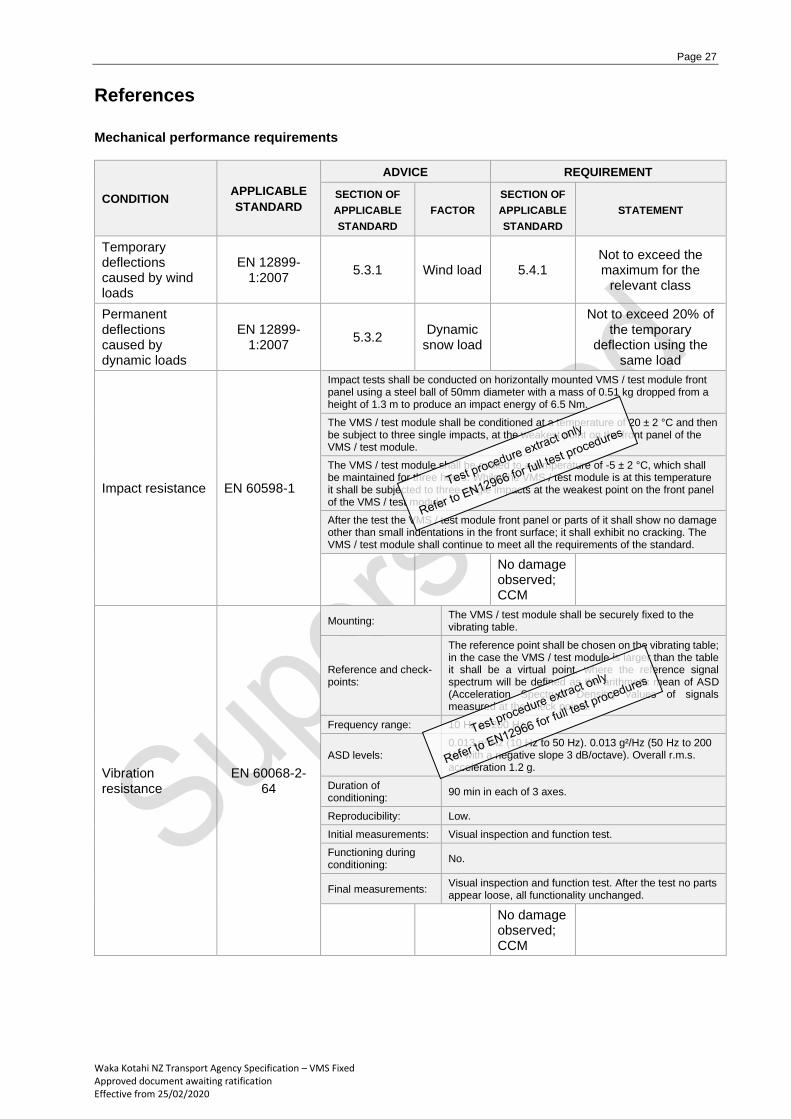
References
Mechanical performance requirements
CONDITION APPLICABLE
STANDARD
ADVICE REQUIREMENT
SECTION OF
APPLICABLE
STANDARD
FACTOR
SECTION OF
APPLICABLE
STANDARD
STATEMENT
Temporary deflections caused by wind loads
EN 12899-1:2007
5.3.1 Wind load 5.4.1 Not to exceed the maximum for the
relevant class
Permanent deflections caused by dynamic loads
EN 12899-1:2007
5.3.2 Dynamic
snow load
Not to exceed 20% of the temporary
deflection using the same load
Impact resistance EN 60598-1
Impact tests shall be conducted on horizontally mounted VMS / test module front panel using a steel ball of 50mm diameter with a mass of 0.51 kg dropped from a height of 1.3 m to produce an impact energy of 6.5 Nm.
The VMS / test module shall be conditioned at a temperature of 20 ± 2 °C and then be subject to three single impacts, at the weakest point on the front panel of the VMS / test module.
The VMS / test module shall be cooled to a temperature of -5 ± 2 °C, which shall be maintained for three hours. Whilst the VMS / test module is at this temperature it shall be subjected to three single impacts at the weakest point on the front panel of the VMS / test module
After the test the VMS / test module front panel or parts of it shall show no damage other than small indentations in the front surface; it shall exhibit no cracking. The VMS / test module shall continue to meet all the requirements of the standard.
No damage observed; CCM
Vibration resistance
EN 60068-2-64
Mounting: The VMS / test module shall be securely fixed to the vibrating table.
Reference and check-points:
The reference point shall be chosen on the vibrating table; in the case the VMS / test module is larger than the table it shall be a virtual point, where the reference signal spectrum will be defined as the arithmetic mean of ASD (Acceleration Spectrum Density) values of signals measured at the check points.
Frequency range: 10 Hz to 200 Hz.
ASD levels: 0.013 g²/Hz (10 Hz to 50 Hz). 0.013 g²/Hz (50 Hz to 200 Hz with a negative slope 3 dB/octave). Overall r.m.s. acceleration 1.2 g.
Duration of conditioning:
90 min in each of 3 axes.
Reproducibility: Low.
Initial measurements: Visual inspection and function test.
Functioning during conditioning:
No.
Final measurements: Visual inspection and function test. After the test no parts appear loose, all functionality unchanged.
No damage observed; CCM
Page 28
Waka Kotahi NZ Transport Agency Specification – VMS Fixed Approved document awaiting ratification Effective from 25/02/2020
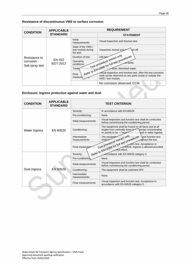
Resistance of discontinuous VMS to surface corrosion
CONDITION APPLICABLE
STANDARD
REQUIREMENT
STATEMENT
Resistance to corrosion -
Salt spray test
EN ISO 9227:2012
Initial measurements:
Visual inspection and function test.
State of the VMS / test module during the test:
Unpacked, locked and switched off.
Duration of test: 240 hrs
Operating conditions:
35 °C ± 2 °C, neutral salt spray
Treatment after test: Rinse with fresh, deionised water
Final measurements:
Visual inspection and function test. After the test corrosion shall not be observed on any parts inside or outside the VMS / test module.
No corrosion observed; CCM
Enclosure: Ingress protection against water and dust
CONDITION APPLICABLE
STANDARD TEST CRITERION
Water ingress EN 60529
Severity: In accordance with EN 60529.
Pre-conditioning: None.
Initial measurements: Visual inspection and function test shall be conducted before commencing the conditioning period.
Conditioning: The equipment shall be hosed on all faces and at all angles from vertically down to horizontal concentrating on points to be ―”most likely” to result in water ingress.
Intermediate measurements:
The equipment shall be switched on and function test shall be continuously repeated throughout the test.
Final measurements: Visual inspection and function test. Acceptance in accordance with EN 60529. Ingress is allowed provided it has no harmful effect.
Dust ingress EN 60529
Severity: In accordance with EN 60529 category 2.
Pre-conditioning: None.
Initial measurements: Visual inspection and function test shall be conducted before commencing the conditioning period.
Conditioning: The equipment shall be switched OFF.
Intermediate measurements:
None.
Final measurements: Visual inspection and function test. Acceptance in accordance with EN 60529 category 2.
Page 29
Waka Kotahi NZ Transport Agency Specification – VMS Fixed Approved document awaiting ratification Effective from 25/02/2020
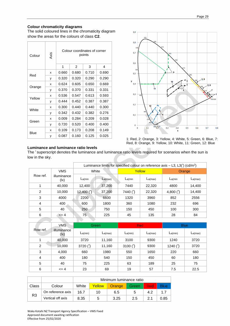
Colour chromaticity diagrams The solid coloured lines in the chromaticity diagram
show the areas for the colours of class C2.
Colour
Axis
Colour coordinates of corner points
1 2 3 4
Red x 0.660 0.680 0.710 0.690
y 0.320 0.320 0.290 0.290
Orange x 0.624 0.605 0.650 0.669
y 0.370 0.370 0.331 0.331
Yellow x 0.536 0.547 0.613 0.593
y 0.444 0.452 0.387 0.387
White x 0.300 0.440 0.440 0.300
y 0.342 0.432 0.382 0.276
Green x 0.009 0.284 0.209 0.028
y 0.720 0.520 0.400 0.400
Blue x 0.109 0.173 0.208 0.149
y 0.087 0.160 0.125 0.025
Luminance and luminance ratio levels The * superscript denotes the luminance and luminance ratio levels required for scenarios when the sun is
low in the sky.
Luminance limits for specified colour on reference axis – L3, L3(*) (cd/m2)
Row ref.
VMS
illuminance (lx)
White Yellow Orange
La(min La(max) La(min La(max) La(min La(max)
1 40,000 12,400 37,200 7440 22,320 4800 14,400
2 10,000 12,400 (*) 37,200 7440 (*) 22,320 4,800 (*) 14,400
3 4000 2200 6600 1320 3960 852 2556
4 400 600 1800 360 1080 232 696
5 40 250 750 150 450 100 300
6 <= 4 75 225 45 135 28 84
Row ref.
VMS
illuminance (lx)
Green Red Blue
La(min) La(max) La(min) La(max) La(min) La(max)
1 40,000 3720 11,160 3100 9300 1240 3720
2 10,000 3720 (*) 11,160 3100 (*) 9300 1240 (*) 3720
3 4,000 660 1980 550 1650 220 660
4 400 180 540 150 450 60 180
5 40 75 225 63 189 25 75
6 <= 4 23 69 19 57 7.5 22.5
Minimum luminance ratio
Class Colour White Yellow Orange Green Red Blue
R3 On reference axis 16.7 10 6.5 5 4.2 1.7
Vertical off axis 8.35 5 3.25 2.5 2.1 0.85
1: Red, 2: Orange, 3: Yellow, 4: White, 5: Green, 6: Blue, 7: Red, 8: Orange, 9: Yellow, 10: White, 11: Green, 12: Blue
Page 30
Waka Kotahi NZ Transport Agency Specification – VMS Fixed Approved document awaiting ratification Effective from 25/02/2020
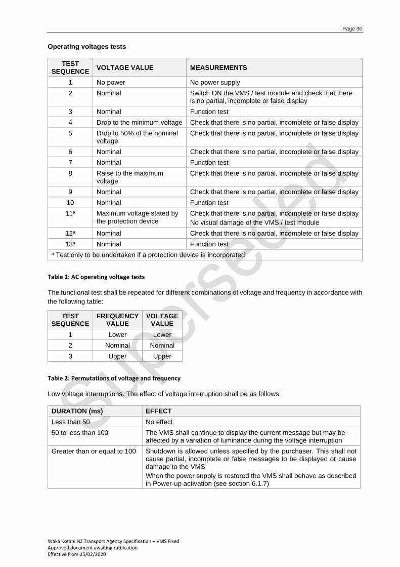
Operating voltages tests
TEST SEQUENCE
VOLTAGE VALUE MEASUREMENTS
1 No power No power supply
2 Nominal Switch ON the VMS / test module and check that there is no partial, incomplete or false display
3 Nominal Function test
4 Drop to the minimum voltage Check that there is no partial, incomplete or false display
5 Drop to 50% of the nominal voltage
Check that there is no partial, incomplete or false display
6 Nominal Check that there is no partial, incomplete or false display
7 Nominal Function test
8 Raise to the maximum voltage
Check that there is no partial, incomplete or false display
9 Nominal Check that there is no partial, incomplete or false display
10 Nominal Function test
11a Maximum voltage stated by the protection device
Check that there is no partial, incomplete or false display
No visual damage of the VMS / test module
12a Nominal Check that there is no partial, incomplete or false display
13a Nominal Function test
a Test only to be undertaken if a protection device is incorporated
Table 1: AC operating voltage tests The functional test shall be repeated for different combinations of voltage and frequency in accordance with
the following table:
TEST SEQUENCE
FREQUENCY VALUE
VOLTAGE VALUE
1 Lower Lower
2 Nominal Nominal
3 Upper Upper
Table 2: Permutations of voltage and frequency Low voltage interruptions. The effect of voltage interruption shall be as follows:
DURATION (ms) EFFECT
Less than 50 No effect
50 to less than 100 The VMS shall continue to display the current message but may be affected by a variation of luminance during the voltage interruption
Greater than or equal to 100 Shutdown is allowed unless specified by the purchaser. This shall not cause partial, incomplete or false messages to be displayed or cause damage to the VMS
When the power supply is restored the VMS shall behave as described in Power-up activation (see section 6.1.7)