itp materials: presentation - stress-assisted corrosion ... · pdf fileto clarify mechanisms...
TRANSCRIPT

StressStress--Assisted Corrosion (SAC) in Assisted Corrosion (SAC) in Boiler TubesBoiler Tubes
Preet M. Singh* and Steve J. Preet M. Singh* and Steve J. PawelPawel@ @
* Georgia Institute Technology, Atlanta, GA* Georgia Institute Technology, Atlanta, GA@ Oak Ridge National Laboratory, Oak Ridge, TN@ Oak Ridge National Laboratory, Oak Ridge, TN
DOE Project #DEDOE Project #DE--FC07FC07--01ID144301ID1443
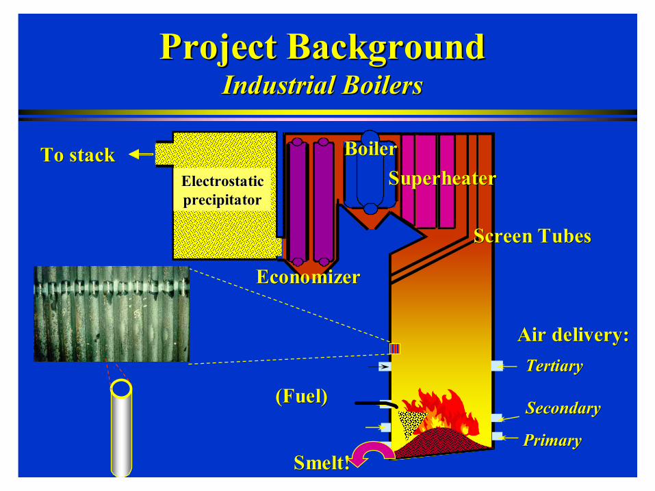
Project BackgroundProject BackgroundIndustrial BoilersIndustrial Boilers
To stackTo stackElectrostaticElectrostaticprecipitatorprecipitator
PrimaryPrimary
SecondarySecondary
TertiaryTertiary
Air delivery:Air delivery:
(Fuel)(Fuel)
Smelt!Smelt!
EconomizerEconomizer
BoilerBoilerSuperheaterSuperheater
Screen TubesScreen Tubes

Stress Assisted Corrosion in Waterwall TubesStress Assisted Corrosion in Waterwall Tubes
Boilers can experience SAC from watersideBoilers can experience SAC from waterside ininFloorFloorWaterwallsWaterwallsScreensScreensRoofRoof
Stress Assisted Corrosion/ CrackingStress Assisted Corrosion/ Cracking
Welded Plate/JointWelded Plate/Joint
EconomizersEconomizersFloorFloor--to Sidewall Sealsto Sidewall SealsSmelt Box AttachmentsSmelt Box AttachmentsPort AttachmentsPort Attachments
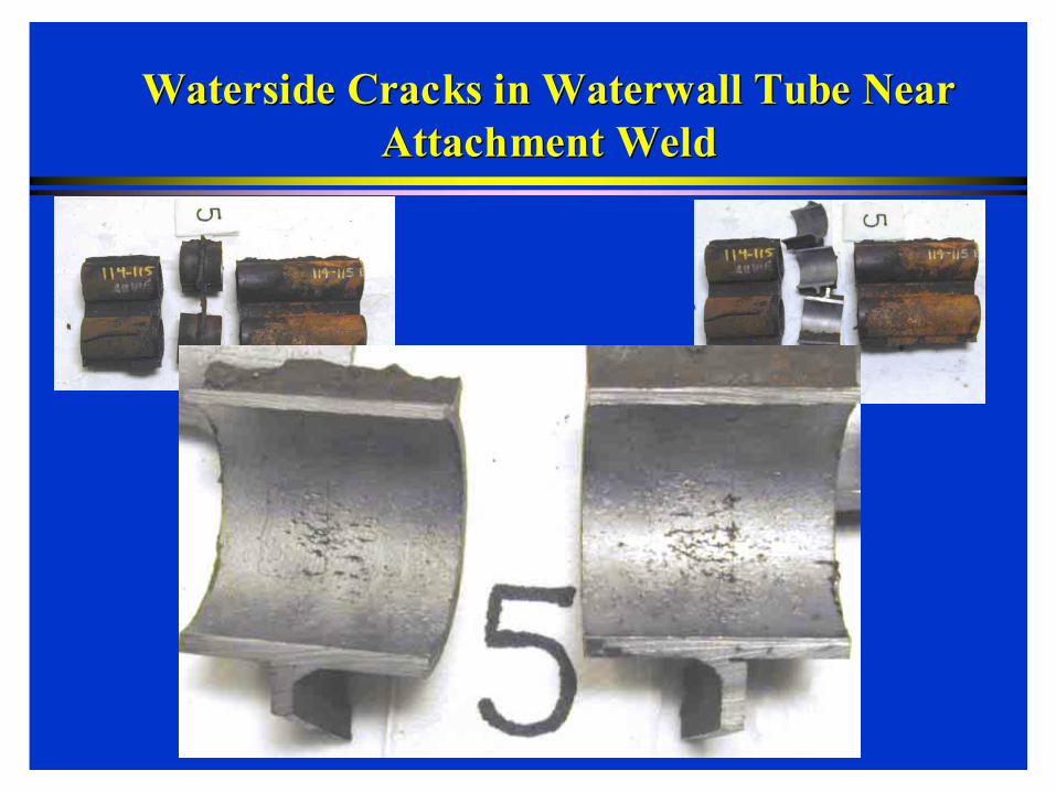
Waterside Cracks in Waterwall Tube Near Waterside Cracks in Waterwall Tube Near Attachment WeldAttachment Weld

SAC in Recovery Boiler TubesSAC in Recovery Boiler Tubes
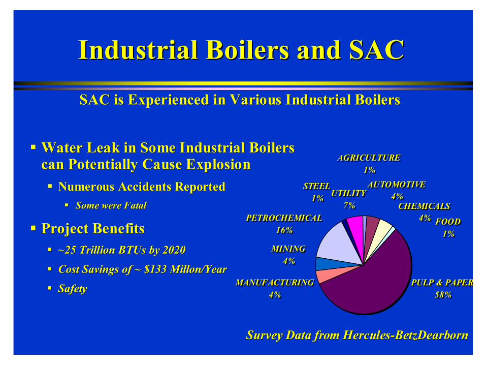
Industrial Boilers and SACIndustrial Boilers and SAC
Water Leak in Some Industrial Boilers Water Leak in Some Industrial Boilers can Potentially Cause Explosioncan Potentially Cause Explosion
Numerous Accidents ReportedNumerous Accidents ReportedSome were FatalSome were Fatal
Project BenefitsProject Benefits~25 Trillion BTUs by 2020~25 Trillion BTUs by 2020
Cost Savings of ~ $133 Cost Savings of ~ $133 MillonMillon/Year/Year
SafetySafety
STEEL 1%
PULP & PAPER58%
MANUFACTURING4%
MINING4%
PETROCHEMICAL16%
UTILITY 7%
AGRICULTURE1%
CHEMICALS 4% FOOD
1%
AUTOMOTIVE 4%
STEEL 1%
PULP & PAPER58%
MANUFACTURING4%
MINING4%
PETROCHEMICAL16%
UTILITY 7%
AGRICULTURE1%
CHEMICALS 4% FOOD
1%
AUTOMOTIVE 4%
Survey Data from HerculesSurvey Data from Hercules--BetzDearbornBetzDearborn
SAC is Experienced in Various Industrial BoilersSAC is Experienced in Various Industrial Boilers

Project ObjectiveProject Objective
To Clarify Mechanisms Involved in Stress Assisted To Clarify Mechanisms Involved in Stress Assisted Corrosion (SAC) of Boiler Tubes Corrosion (SAC) of Boiler Tubes
Determine KDetermine Key Parameters in its Mitigation and Controley Parameters in its Mitigation and Control
MicrostructureMicrostructure
Water ChemistryWater Chemistry
Stress Stress
Residual Stresses Due to Welding Residual Stresses Due to Welding
Operational StressesOperational Stresses
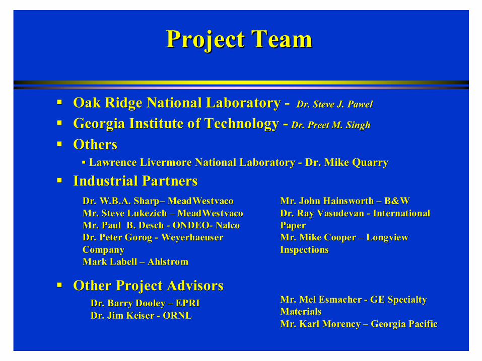
Project TeamProject Team
Oak Ridge National Laboratory Oak Ridge National Laboratory -- Dr. Steve J. Dr. Steve J. PawelPawel
Georgia Institute of Technology Georgia Institute of Technology -- Dr. Preet M. SinghDr. Preet M. Singh
Others Others Lawrence Livermore National Laboratory Lawrence Livermore National Laboratory -- Dr. Mike QuarryDr. Mike Quarry
Industrial PartnersIndustrial Partners
Other Project AdvisorsOther Project Advisors
Mr. John Mr. John HainsworthHainsworth –– B&W B&W Dr. Ray Dr. Ray VasudevanVasudevan -- International International PaperPaperMr. Mike Cooper Mr. Mike Cooper –– Longview Longview InspectionsInspections
Dr. W.B.A. SharpDr. W.B.A. Sharp–– MeadWestvacoMeadWestvacoMr. Steve Mr. Steve LukezichLukezich –– MeadWestvacoMeadWestvacoMr. Paul B. Mr. Paul B. DeschDesch -- ONDEOONDEO-- NalcoNalcoDr. Peter Dr. Peter GorogGorog -- Weyerhaeuser Weyerhaeuser CompanyCompanyMark Mark LabellLabell –– AhlstromAhlstrom
Dr. Barry Dooley Dr. Barry Dooley –– EPRIEPRIDr. Jim Keiser Dr. Jim Keiser -- ORNLORNL
Mr. Mel Mr. Mel EsmacherEsmacher -- GE Specialty GE Specialty Materials Materials Mr. Karl Mr. Karl MorencyMorency –– Georgia PacificGeorgia Pacific

Main Project TasksMain Project TasksTask 1: Task 1: Laboratory Simulation of SACLaboratory Simulation of SAC
IPSTIPST--GTechGTech
Task 2: Task 2: Material CharacterizationMaterial Characterization[ORNL and IPST[ORNL and IPST--GTechGTech]]
Task 3: Task 3: Evaluation of Stress Effects Evaluation of Stress Effects [ORNL][ORNL]
Task 4: Task 4: Evaluation of Environmental Effects Evaluation of Environmental Effects [IPST[IPST--GTechGTech and ORNL]and ORNL]
Task 5: Task 5: Communication to US Industry Communication to US Industry [IPST[IPST--GTechGTech and ORNL]and ORNL]
Laboratory Simulation of SAC Laboratory Simulation of SAC Task 1Task 1
Develop Facilities to Simulate Boiler Tube Develop Facilities to Simulate Boiler Tube Environment in LaboratoryEnvironment in Laboratory
Capable of Controlling WaterCapable of Controlling Water--Chemistry Chemistry VariablesVariables
Dissolved OxygenDissolved Oxygen
pHpH
ClCl--, SO, SO44--22, and Other Ions, and Other Ions
ConductivityConductivity
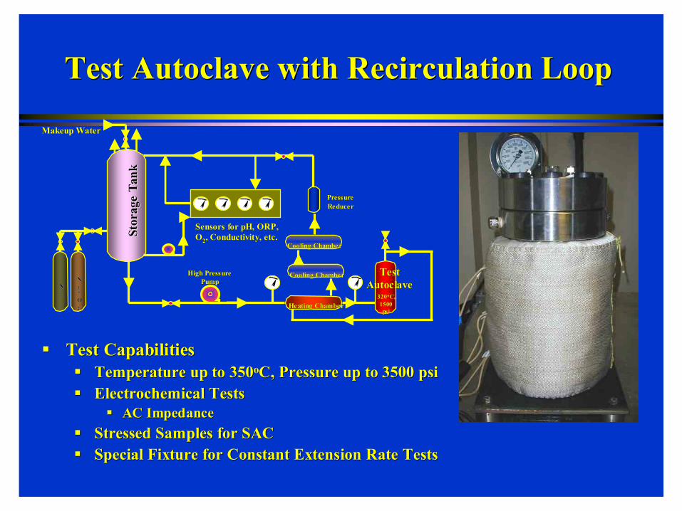
Test Autoclave with Recirculation LoopTest Autoclave with Recirculation Loop
Test CapabilitiesTest CapabilitiesTemperature up to 350Temperature up to 350ooC, Pressure up to 3500 C, Pressure up to 3500 psipsiElectrochemical TestsElectrochemical Tests
AC ImpedanceAC ImpedanceStressed Samples for SACStressed Samples for SACSpecial Fixture for Constant Extension Rate TestsSpecial Fixture for Constant Extension Rate Tests
Cooling ChamberCooling Chamber
Test Test AutoclaveAutoclave
Heating ChamberHeating Chamber
High Pressure High Pressure PumpPump
Pressure Pressure ReducerReducer
Stor
age
Tank
Stor
age
Tank
Makeup WaterMakeup Water
320320ooC, C, 1500 1500 psipsi
Sensors for pH, ORP, Sensors for pH, ORP, OO22, Conductivity, etc., Conductivity, etc.
NN22
NN2 2 + + OO22
Cooling ChamberCooling Chamber

Autoclave with Recirculation LoopAutoclave with Recirculation Loop
100 Liter Makeup Tank100 Liter Makeup Tank
Heat Exchangers to Conserve Heat and Achieve Steady State EasilyHeat Exchangers to Conserve Heat and Achieve Steady State Easily
High Pressure Pump for RecirculationHigh Pressure Pump for Recirculation
Continuous Water Chemistry MonitoringContinuous Water Chemistry Monitoring
Evaluation of Environmental EffectsEvaluation of Environmental EffectsTask 4Task 4
Effect of Environment on Magnetite Growth and Effect of Environment on Magnetite Growth and PropertiesProperties

Boiler Environment and Magnetite Film on Boiler Environment and Magnetite Film on Tube SurfaceTube Surface
3 Fe + 4 H3 Fe + 4 H22O → O → FeFe33OO44 + 4 H+ 4 H22
14121086420
2.0
1.5
1.0
0.5
0.0
-0.5
-1.0
-1.5
-2.0
Fe - H2O - System at 320.00 C
C:\HSC5\EpH\Fe320.iep pH
Eh (Volts)
H2OFe
Fe2O3
Fe3O4Fe(+2a)
FeO2(-a)
ELEMENTS Molality PressureFe 1.000E+00 1.112E+02
Above ~ 230Above ~ 230ooC, Magnetite Film Forms on Carbon C, Magnetite Film Forms on Carbon Steel in Slightly Alkaline OxygenSteel in Slightly Alkaline Oxygen--free Waterfree Water

Stress Assisted Corrosion and Oxide Stress Assisted Corrosion and Oxide Scale MorphologyScale Morphology
Magnetite Film Growth and Morphology Magnetite Film Growth and Morphology Under Boiler ConditionsUnder Boiler Conditions
SA 210 Carbon Steel Tube SamplesSA 210 Carbon Steel Tube Samples
Electrically Isolated SamplesElectrically Isolated Samples
Samples Attached to Large Cathodes with Different Areas Samples Attached to Large Cathodes with Different Areas
Pure Water Pure Water (Double(Double--DeionizedDeionized))
With and Without NWith and Without N22 Purge or OPurge or O22 ScavengerScavenger
250250ooC to 320C to 320ooCC
XX--Ray Diffraction of Sample Surface and Ray Diffraction of Sample Surface and MetallographyMetallography to Characterize Film to Characterize Film
Atomic Force Microscopy (AFM) for Film Morphology Atomic Force Microscopy (AFM) for Film Morphology and Propertiesand Properties

Atomic Force MicroscopyAtomic Force MicroscopyUnexposed SAUnexposed SA--210 Carbon Steel Surface210 Carbon Steel Surface
Topography ScanTopography ScanMax. Roughness = 10 nmMax. Roughness = 10 nm
10
8
6
4
2
0
µm
1086420µm
-30
-20
-10
0
10
20
30
nm

Electrically Isolated SAElectrically Isolated SA--210 Carbon Steel Exposed to 210 Carbon Steel Exposed to DeaeratedDeaerated DI Water at 320DI Water at 320ooC for 114 hoursC for 114 hours
SA210- Carbon Steel (Electrically isolated), in Deaereated DI water at 320C for 144h
0
10
20
30
40
50
60
70
80
90
100
1.000 1.500 2.000 2.500 3.000 3.500 4.000 4.500 5.000d/[A]
Rel
ativ
e In
tens
ity
Fe
Fe
Fe3O4
Fe3O4 Fe3O4
Fe3O4Fe2O3

Electrically Isolated SAElectrically Isolated SA--210 Carbon Steel Exposed to 210 Carbon Steel Exposed to DeaeratedDeaerated DI Water at 320DI Water at 320ooC for 114 hoursC for 114 hours
10
8
6
4
2
0
µm
1086420µm
1.5
1.0
0.5
0.0
-0.5
-1.0µm
Electrically Isolated CElectrically Isolated C--Steel Steel in Boiler Environment in Boiler Environment Forms Dense and Protective Forms Dense and Protective Magnetite Film on SurfaceMagnetite Film on Surface

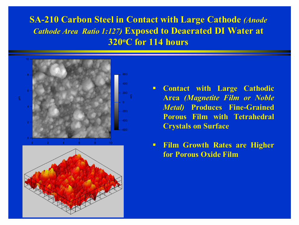
SASA--210 Carbon Steel in Contact with Large Cathode 210 Carbon Steel in Contact with Large Cathode (Anode (Anode Cathode Area Ratio 1:127)Cathode Area Ratio 1:127) Exposed to Exposed to DeaeratedDeaerated DI Water at DI Water at
320320ooC for 114 hoursC for 114 hours
SA210- Carbon Steel (Anode-Cathode ratio 1:127), in Deaereated DI water at 320C for 144h
0
10
20
30
40
50
60
70
80
90
100
1.000 1.500 2.000 2.500 3.000 3.500 4.000 4.500 5.000d/[A]
Rel
ativ
e In
tens
ity
Fe
Fe
Fe3O4
Fe3O4Fe3O4
Fe3O4
Fe2O3
Fe2O3
10
8
6
4
2
0
µm
1086420µm
-600
-400
-200
0
200
400
600
nm
SASA--210 Carbon Steel in Contact with Large Cathode 210 Carbon Steel in Contact with Large Cathode (Anode (Anode Cathode Area Ratio 1:127)Cathode Area Ratio 1:127) Exposed to Exposed to DeaeratedDeaerated DI Water at DI Water at
320320ooC for 114 hoursC for 114 hours
Contact with Large Contact with Large CathodicCathodicArea Area (Magnetite Film or Noble (Magnetite Film or Noble Metal)Metal) Produces FineProduces Fine--Grained Grained Porous Film with Tetrahedral Porous Film with Tetrahedral Crystals on SurfaceCrystals on Surface
Film Growth Rates are Higher Film Growth Rates are Higher for Porous Oxide Filmfor Porous Oxide Film

Proposed SAC Initiation Mechanism Proposed SAC Initiation Mechanism ––Based on Film Growth ResultsBased on Film Growth Results
Initially Thin Dense Magnetite Film is Formed on CInitially Thin Dense Magnetite Film is Formed on C--Steel Tube Steel Tube SurfacesSurfaces
New Tubes or Acid Cleaned Tubes New Tubes or Acid Cleaned Tubes
If Thin Protective Magnetite Film is Locally Disrupted If Thin Protective Magnetite Film is Locally Disrupted (Stress Effects)(Stress Effects)
Remaining Intact Magnetite on the Tube Will Act as Remaining Intact Magnetite on the Tube Will Act as CathodicCathodic SurfaceSurface
New Oxide Growth in the Damaged Areas may Form Porous Oxide FilmNew Oxide Growth in the Damaged Areas may Form Porous Oxide Film
Further Damage Accumulation by Disruption or Fracture of Porous Further Damage Accumulation by Disruption or Fracture of Porous Film Due to Stress Concentration at Notches DevelopedFilm Due to Stress Concentration at Notches Developed
SAC Initiation and Growth!!SAC Initiation and Growth!!
Further Tests Going on to Test This MechanismFurther Tests Going on to Test This Mechanism

Material CharacterizationMaterial CharacterizationTask 2Task 2
Tubes from Over Ten Boilers Analyzed at Tubes from Over Ten Boilers Analyzed at GTechGTech and ORNLand ORNL
Role of Microstructure on SAC Initiation and PropagationRole of Microstructure on SAC Initiation and Propagation--RateRate

Inner Tube SurfaceInner Tube Surface Middle of TubeMiddle of Tube
Microstructure of Carbon Steel Tubes With SACMicrostructure of Carbon Steel Tubes With SAC
Not Necessary for SAC but may facilitate easier InitiationNot Necessary for SAC but may facilitate easier Initiation

MicrohardnessMicrohardness and Microstructure and Microstructure
Microhardness as Function of Distance from Inner Surface
100
110
120
130
140
150
160
170
180
190
0 500 1000 1500 2000 2500 3000 3500 4000
Distance from Inner Surface (microns)
Mic
roha
rdne
ss (V
HN
)
WV5-161WV-160WV-160-LittleWV7-143WV4-161

Microstructure of Composite Tubes Removed from Front Microstructure of Composite Tubes Removed from Front Wall Wall (near smelt spouts)(near smelt spouts) of Recovery Boilers of Recovery Boilers
No SAC in these TubesNo SAC in these Tubes
Evaluation of Stress Effects Evaluation of Stress Effects Task 3Task 3
Finite Element Modeling Finite Element Modeling -- Effect of Effect of Attachment Plate on Recovery Boiler Wall Attachment Plate on Recovery Boiler Wall Panel Stresses Panel Stresses –– GortiGorti SarmaSarma -- ORNLORNL
Stress Measurements on Boiler TubesStress Measurements on Boiler Tubes
SSRT Tests in Simulation AutoclaveSSRT Tests in Simulation Autoclave

Temperature Distribution in the PanelTemperature Distribution in the Panel
Uniform heat flux of 0.3 W/mmUniform heat flux of 0.3 W/mm22 was applied on the fireside of the panelwas applied on the fireside of the panel
Tube inside surface was assumed to be in contact with water at 3Tube inside surface was assumed to be in contact with water at 30505°°CC
Cold side of panel was assumed to be exposed to air at 100Cold side of panel was assumed to be exposed to air at 100°°CC
Attachment Attachment PlatePlate

Stress Distribution Due to Temperature DifferencesStress Distribution Due to Temperature Differences
Load due to pressurized water on inside surface of tube was 8.62Load due to pressurized water on inside surface of tube was 8.62 MPaMPaResidual stress values calculated from 2Residual stress values calculated from 2--D welding analyses D welding analyses Stresses due to welding of attachment plate to the wall panel weStresses due to welding of attachment plate to the wall panel were not re not included in this initial analysesincluded in this initial analyses
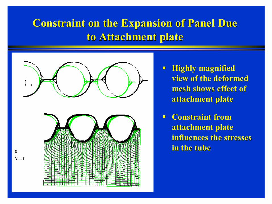
Constraint on the Expansion of Panel Due Constraint on the Expansion of Panel Due to Attachment plateto Attachment plate
Highly magnified Highly magnified view of the deformed view of the deformed mesh shows effect of mesh shows effect of attachment plateattachment plate
Constraint from Constraint from attachment plate attachment plate influences the stresses influences the stresses in the tubein the tube

Attachment Plate Constraint on Deformation of Wall Attachment Plate Constraint on Deformation of Wall Tube Panel Due to Operational Hoop StressesTube Panel Due to Operational Hoop Stresses
Attachment plate causes changes in stress state in the Attachment plate causes changes in stress state in the vicinity of the weld, with fairly sharp gradientsvicinity of the weld, with fairly sharp gradients
Stresses change significantly on either side over a length of 3 Stresses change significantly on either side over a length of 3 elements, which is about 18.3 mm (0.72 in.)elements, which is about 18.3 mm (0.72 in.)

Hoop Stresses at Inside Surface Under Operating Hoop Stresses at Inside Surface Under Operating Cycles for Panel Tubes without Attachment PlateCycles for Panel Tubes without Attachment Plate
Hoop stress at the inside surface of tube crown on the cold Hoop stress at the inside surface of tube crown on the cold side becomes slightly tensile during operation, but returns side becomes slightly tensile during operation, but returns to initial value upon shutdownto initial value upon shutdown

Hoop Stresses at Inside Surface Under Operating Hoop Stresses at Inside Surface Under Operating Cycles for Panel Tubes with Attachment PlateCycles for Panel Tubes with Attachment Plate
Hoop stress at the inside surface of tube at the weld becomes Hoop stress at the inside surface of tube at the weld becomes slightly tensile at operating temperature, and even more tensileslightly tensile at operating temperature, and even more tensileafter shutdownafter shutdown
Hoop stress remains tensile during subsequent operating cyclesHoop stress remains tensile during subsequent operating cycles

•• Identify a Boiler with Known SAC Problem Identify a Boiler with Known SAC Problem AreasAreas
•• Make installation during outage (prior to Make installation during outage (prior to restart)restart)
•• -- $50K budgeted for gages, equipment$50K budgeted for gages, equipment
•• Collect data every 15Collect data every 15--30 seconds for 630 seconds for 6++ monthsmonths
•• Use data to support finite element modelUse data to support finite element model
•• Attempt postAttempt post--test evaluation of the test evaluation of the instrumented areasinstrumented areas
-- radiography, radiography, ultrasonicsultrasonics, , borescopeborescope
Stress Measurements on Boiler TubesStress Measurements on Boiler Tubes
scallopscallop--typetypeattachment weldattachment weld
tube crown
tube crown3030 °°
6060 °°
membranemembrane
Circumferential and longitudinal gagesCircumferential and longitudinal gages
Circumferential gages onlyCircumferential gages only

Future Tasks for FY 05 Role of Water Chemistry on Magnetite Film Formation and its Role of Water Chemistry on Magnetite Film Formation and its PropertiesProperties
XX--Ray Diffraction, SEM and AFM Analysis of Films to Characterize Ray Diffraction, SEM and AFM Analysis of Films to Characterize Composition, Morphology, and Mechanical PropertiesComposition, Morphology, and Mechanical Properties
Role of Microstructure on SAC Initiation and Propagation Role of Microstructure on SAC Initiation and Propagation –– Tests on As Tests on As Received and Heat Treated Steels Received and Heat Treated Steels
More Failure Analysis of Tubes Removed from BoilersMore Failure Analysis of Tubes Removed from Boilers
Continue FEM Modeling to Calculate Inner Tube Surface Strains AtContinue FEM Modeling to Calculate Inner Tube Surface Strains AtAttachment WeldsAttachment Welds
SSRT Tests to Evaluate Role of Stress on SAC Initiation and SSRT Tests to Evaluate Role of Stress on SAC Initiation and PropagationPropagation
Strain Gages on Boiler Tubes with Attachment to Measure Strains Strain Gages on Boiler Tubes with Attachment to Measure Strains Experienced During Startup and Shutdown as well as During OperatExperienced During Startup and Shutdown as well as During Operationion


Energy SavingsEnergy Savings
Impact by the year 2020
ENERGY SAVINGS Electricity Gas Oil Coal
Total Energy Savings
Vision Industry
[billion kWh]
[billion ft3]
[million barrels]
[million tons]
[trillion BTU's]
Petrochemical 0.13 4.0 0.05 0.04 6.25 Chemical 0.08 2.3 0.025 0.01 5.5
Other Manf. 0.07 2.2 0.025 0.01 5.0 Metal 0.05 1.8 0.02 0.01 2.5 Glass 0.07 2.0 0.02 0.01 3.0 Paper 0.02 0.05 0.002 .003 0.75
Total Savings 0.42 12.4 0.14 0.083 23

Energy Impact Energy Impact (in Dollars)(in Dollars)
Impact by the Year 2020 Energy Cost Savings
Vision Industry Energy Savings [Million $/Year]
Petrochemical 48 Chemical 28 Other Manufacturing 25 Metal 12 Glass 15 Paper 5 Total 133
Impact by the Year 2020 Energy Cost Savings
Vision Industry Energy Savings [Million $/Year]
Petrochemical 48 Chemical 28 Other Manufacturing 25 Metal 12 Glass 15 Paper 5 Total 133

Project Status SummaryProject Status SummaryTask ID
Milestone Planned Completion
Actual Completion Comments
1.0 Lab simulation of SAC
1.1 Establish autoclave operation
April 2003 Completed Autoclave and heaters are working satisfactorily
1.2 Develop tensile test rig
August 2003 Completed
1.3 Simulate SAC in lab tests
Sept. 2004 On-Going
1.4 Oxide growth experiments
Sept 2004 On-Going
2.0 Material characterization
2.1 Examine tubes with SAC
Sept. 2003 Completed (On-Going)
Various tubes were received and were examined at ORNL and IPST
2.2 Document inspection reports
Dec. 2003 NA
2.3 Inspections to assess SAC rate
Sept. 2004 On-Going
3.0 Evaluation of stress effects
3.1 Document failure reports
April 2004 Some data was received and is being reviewed. Required information is missing in most cases
3.2 Deploy field strain gages
Dec. 2004 On-Going
3.3 Model internal stress/strains
On-Going
4.0 Environmental effects
4.1 Assess key chemistry data
Mar. 2005 On-Going
4.2 Deploy on-line monitoring
April 2005
4.3 Document effect of cleaning
Sept. 2005
5.0 Communication to US industry
Presentations were made at TAPPI and NACE meetings and appropriate Committees attended by US industry reps.
5.1 Technical review meetings
Every six months Second meeting will be held in June 2003
Task ID
Milestone Planned Completion
Actual Completion Comments
1.0 Lab simulation of SAC
1.1 Establish autoclave operation
April 2003 Completed Autoclave and heaters are working satisfactorily
1.2 Develop tensile test rig
August 2003 Completed
1.3 Simulate SAC in lab tests
Sept. 2004 On-Going
1.4 Oxide growth experiments
Sept 2004 On-Going
2.0 Material characterization
2.1 Examine tubes with SAC
Sept. 2003 Completed (On-Going)
Various tubes were received and were examined at ORNL and IPST
2.2 Document inspection reports
Dec. 2003 NA
2.3 Inspections to assess SAC rate
Sept. 2004 On-Going
3.0 Evaluation of stress effects
3.1 Document failure reports
April 2004 Some data was received and is being reviewed. Required information is missing in most cases
3.2 Deploy field strain gages
Dec. 2004 On-Going
3.3 Model internal stress/strains
On-Going
4.0 Environmental effects
4.1 Assess key chemistry data
Mar. 2005 On-Going
4.2 Deploy on-line monitoring
April 2005
4.3 Document effect of cleaning
Sept. 2005
5.0 Communication to US industry
Presentations were made at TAPPI and NACE meetings and appropriate Committees attended by US industry reps.
5.1 Technical review meetings
Every six months Second meeting will be held in June 2003