iterative equalization and decoding - ieee iterative equalization and decoding john g. proakis...
TRANSCRIPT


2
Conventional Equalization
Equalizer DecoderSoft OutputFrom Receiver
FilterHard Output
Possible Equalizer Types:•Linear Equalizer•Decision Feedback Equalizer (DFE)•Maximum A posteriori Probability (MAP) Equalizer•Soft-output Viterbi (MLSE) Equalizer
Possible Decoder Types:•Maximum A posteriori Probability (MAP) Decoder•Viterbi (MLSE) Decoder

3
Turbo Principle / Turbo Coding
d(n)
b(n)
D D+
cs(n)
cp1(n)
D D
Π
cp2(n)
d`(n)
Puncturerand P/S converter
Encoder 1
Encoder 2
+
+
+
Turbo Encoder:• Parallel concatenatedrecursive systematicconvolutional encoders• Encoders separated by an interleaver
Turbo Decoder:• Two Soft-Input Soft-Output (SISO) decoders separated by interleavers• SISO modules can be
• SOVA• MAP
• Extrinsic information passed between modules
Le21
Π−1
SISODecoder 1xp1
xs SISODecoder 2xp2
Π
ΠLe
12
Ld

4
Serially Concatenated Systems
Serially Concatenated Coding:• Serial concatenated(recursive) convolutionalencoders• Encoders separated by an interleaver
Encoder 1d(n)
Πc(n) c’(n) b(n)
Encoder 2
Coded Transmission over Multipath Channels:
• (recursive) convolutionalencoder• Interleaved bits mapped to symbols• Symbols passed through a multipath channel
Encoderd(n)
Πc(n) c’(n) Symbol
Mapper
x(n)
MultipathChannel
r(n)
5
Channel Model / Precoding
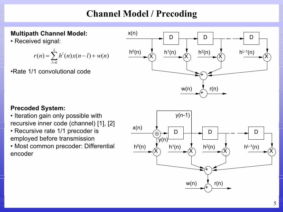
Multipath Channel Model:• Received signal:
•Rate 1/1 convolutional code
D
Xh1(n)
D
Xh2(n)
D
XhL-1(n)
Xh0(n)
+
+w(n)
x(n)
r(n)
)()()()(0
nwlnxnhnrL
l
l +−=∑=
Precoded System:• Iteration gain only possible with recursive inner code (channel) [1], [2]• Recursive rate 1/1 precoder is employed before transmission• Most common precoder: Differential encoder
D
Xh1(n)
D
Xh2(n)
D
XhL-1(n)
Xh0(n)
+
+w(n)
x(n)
r(n)
⊕y(n)
y(n-1)

6
Iterative Equalization and Decoding (Turbo Equalizer)
ConvolutionalEncoder Π Symbol
MapperMultipathChannel
dn cn c’n xn rn
• Data bits are convolutionally encoded and interleaved• M-ary PSK modulated signals transmitted through a multipath channel, which is treated as an encoder
• Received signals are jointly equalized and decoded in a turbo structure• First proposed by Douillard, et.al [3], where SOVA modules are employed• Bauch extended the idea by employing MAP modules [4]
MAPDecoder+ Π
Π−1
MAPEqualizer
+ChannelEstimator
r
LDe(c’) LD
e(c) LD(c)
LD(d)
LEe(c)LE
e(c’)LE(c’)
-
-

7
Time-invariant Test Channel
• Proakis C channel [5]
0.688
0.460
0.227
0.460
0.227
t
Impulse Response Frequency Response

8
Low Complexity Alternative Equalizers: DFE and MLSE
• Performance of DFE and MLSE over the Proakis C channel [5]
Bit error rate performance [5]

9
Iterative Equalization and Decoding Performance
• Iterative equalization and decoding with MAP modules• Recursive systematic convolutional encoder with R=1/2, K=5, • Time-invariant 5 tap channel with a spectral null (Proakis C [5])• Equalizer has perfect knowledge of the channel • Block length 4096
Bit error rate performance of turbo equalizer [4]

10
Hard Iterative DFE and MAP Decoding
ForwardFilter
FeedbackFilter
SymbolDetector
+Input fromreceiver filter
DFE withhard input feedback
kI
kI~
Π−1
ΠHard encoded
symbols
MAPDecoder
OutputData
• During the first pass, symbol detector output is passed to the feedback filter• After the first pass, hard encoded symbol output of the decoder is used in the feedback filter

11
Performance of Hard Iterative DFE and MAP decoder
12 12.5 13 13.5 14 14.5 15 15.510
-6
10-5
10-4
10-3
10-2
10-1
100
Eb/N0 (dB)
PBER
P erformance of Hard Iterative DFE(K1=K2=4) in Coded BP S K S ys tem
Firs t iteration K=7 S econd iteration K=7Third iteration K=7 Fourth iteration K=7
• BPSK modulation• R=1/2, K=7 convolutional coding• Block length 2048• Channel Proakis C

12
Soft Iterative DFE and MAP Decoding
ForwardFilter
FeedbackFilter
DecisionDevice
+
DFE withhard input feedback
kIΠ
−1
ΠSoft encoded
symbols
MAPDecoder
OutputData
Soft decisions of the decoder is combined with the soft outputs of the DFE:
kI2
2σ
×)ˆ( kIL
+Hard detected
symbolsSoft APPfrom lastiteration

13
Histogram of DFE Output
-4 -3 -2 -1 0 1 2 3 40
1 0 0
2 0 0
3 0 0
4 0 0
5 0 0
6 0 0
7 0 0
-5 0 50
2 0 0
4 0 0
6 0 0
8 0 0
10 0 0
12 0 0
14 0 0
16 0 0
18 0 0
20 0 0
The histogram of equalizer estimated output for SNR = 12 dB
The histogram of equalizer estimated output for SNR = 20 dB
14
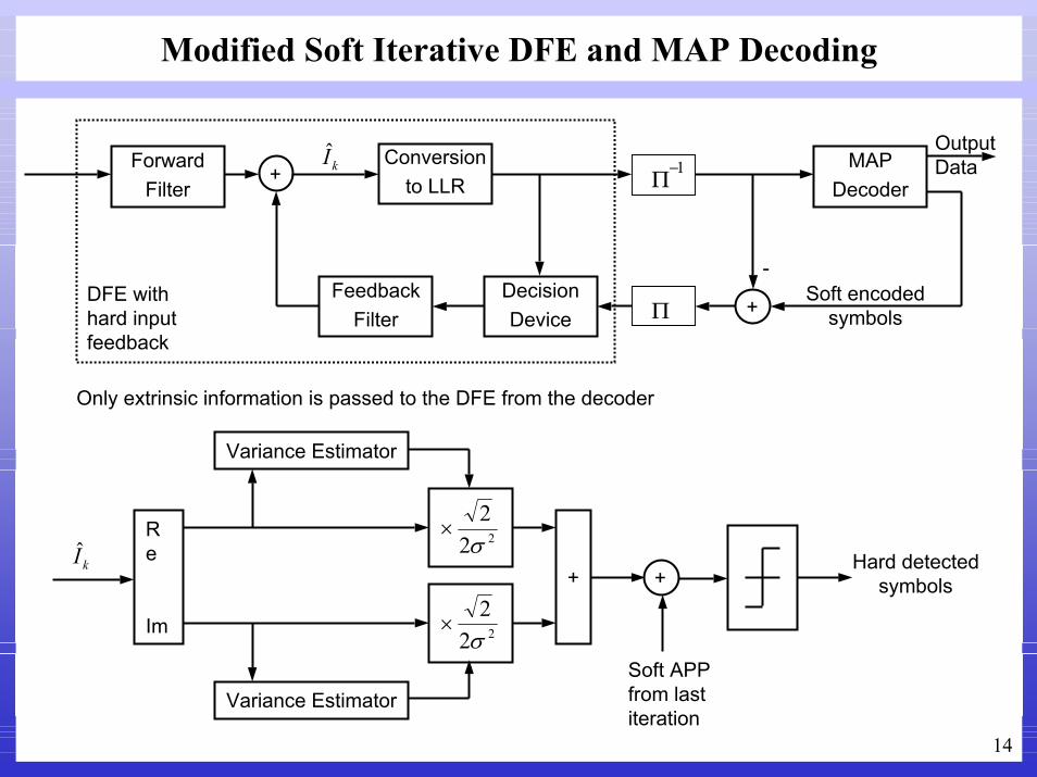
Modified Soft Iterative DFE and MAP Decoding
ForwardFilter
FeedbackFilter
DecisionDevice
+
DFE withhard input feedback
kI Conversionto LLR Π
−1
Π
MAPDecoder
OutputData
Soft encodedsymbols+
-
Only extrinsic information is passed to the DFE from the decoder
Variance Estimator
Re
Im
222σ
×
222σ
×
kI
Variance Estimator
+ +
Soft APPfrom lastiteration
Hard detectedsymbols
15
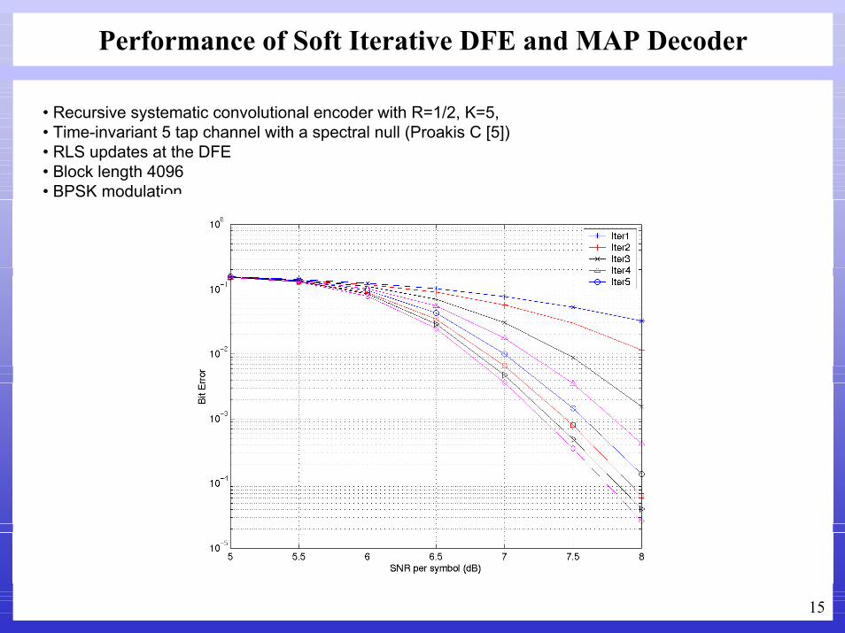
Performance of Soft Iterative DFE and MAP Decoder
• Recursive systematic convolutional encoder with R=1/2, K=5, • Time-invariant 5 tap channel with a spectral null (Proakis C [5])• RLS updates at the DFE• Block length 4096• BPSK modulation

16
Performance of Soft Iterative DFE and MAP Decoder
• Recursive systematic convolutional encoder with R=1/2, K=5, • Time-invariant 5 tap channel with a spectral null (Proakis C [5])• RLS updates at the DFE• Block length 4096• QPSK modulation

17
Iterative Linear MMSE Equalization and Decoding
SISO Linear MMSE Equalizer [6]:• Known channel:
• Received signal:
• Likelihood ratio for MMSE estimator output, :
• Channel matrix:
• MMSE estimator output:
where,
211 ,,1,, MMMkhk L+−−=
∑−=
− +=2
1
M
Mkkknkn xhz ω
nx( )( )
{ }{ }
443442144 344 21)()(
1Pr1Prln
1|ˆ1|ˆln)(
nnMMSEe
xL
n
n
xL
nn
nnn
MMSE
xx
xxpxxpxL
−=+=
+−=+=
=
=
+−−
+−−
+−−
21
2
1
11
211
00
0
00
0
1
1
1
MM
M
M
MM
MMM
hh
h
h
hhhhh
L
L
L
L
O
L
L
H
( ) xn
znn
Hnn mx +−= mzcˆ
( ){ } { }
{ }
==
==
+=−
)(21tanh
),cov(),cov( 12
nnxn
nnzn
nnH
nnN
n
xLxEm
EEx
xHzmxHxxHIc ωσ

18
Iterative Linear MMSE Equalization and Decoding
Steps to compute symbol estimates with the Linear MMSE equalizer:
[ ]( )
[ ]( )
( )sHmzcsssHHDIc
Hs
D
m
H
xn
xnn
Hnn
xn
Hn
Nn
TMNxMNx
xNMn
xNMn
xNMnn
TxNMn
xNMn
xNMn
xn
nxn
mxm
mmmdiag
mmm
xLm
+−=
++=
=
−−−=
=
=
−
++
−−−++++
−−−++++
ˆ)(
010
)(1)(1)(1
)(21tanh
122
)(1)(1
221
2
1
2211
221111
221111
ωσ
L
L
Soft output calculation assuming Gaussian distributed estimates:
{ }{ }
nHn
n
nnn
MMSEe
nHnn
Hnnnn
Hnnnn
xxxL
xxExxE
cs
sc
scsc
−==
−=
−=−==
=+==
+
+
−
+
1ˆ2ˆ2)(
1|ˆ1|ˆ
2
)1(
2)1(2
)1(
)1(
σµ
µσ
µ
µ

19
Performance of SISO MMSE Linear Iterative Equalizer
• Recursive systematic convolutional encoder with R=1/2, K=5, • Time-invariant 5 tap channel with a spectral null (Proakis C [5])• Equalizer has perfect knowledge of the channel • Block length 4096

20
Comparison of System Performances
• Recursive systematic convolutional encoder with R=1/2, K=5, • Time-invariant 5 tap channel with a spectral null (Proakis C [5])• BER results after 6 iterations• Block length 4096

21
Experimental Study of Iterative Equalizers
ChannelProbe
TrainingSymbols
InformationSymbols
DeadTime

22
Joint MMSE Equalization and Turbo Decoding
Le12
Π−1
MAPDecoder 1 Demapper
&S/P
Converter
AdaptiveAlgorithm
x(n)^
xs
xp2
σ2(n)
Π
Π−1
+
xp1
Π
Π
Lp1
FeedbackFilter
DecisionDevice
x(n) TrainingSymbols
x(n)~
e-jθ(n)
e(n)
y(n)
Ld
MAPDecoder 2
Lp2
Le12
ForwardFilter +x

23
Decision Feedback Equalizer (DFE)
• Soft output of the DFE:
•RLS algorithm is used to track channel variation:
)(~)()()()(ˆ nnnnnx HH xwyw bf −=
)(ξ)(~)()1()(
)(ξ)()()1()(
))(~)1()()1(()()(ξ))1()()()1((λ)(
)()1()(λ)()1()(
1-
nnnnn
nnnnn
nnnnnxnnnnnn
nnnnnn
HH
H
H
∗
∗
+−=
+−=
−−−−=
−−−=
−+−
=
xPww
yPww
xwywPykPP
yPyyPk
bb
ff
bf
• Noise variance estimate: 222 ))(~)()()(()(λ)1()1(λσ)(σ nnnnnxnn HH xwyw bf −−−+−=

24
MAP Decoding
• Maximize a posteriori probability:
• Decision variable written in the form of log-likelihood ratio:
1,,1,0),|( −== kiddP in Ly
∑∑=
−=+=
=Λ
− −
+ −
==
==
S nn
S nn
pssssp
pssssp
n
n
dPdPdn
)(/),,'(
)(/),,'(
1
1log
)|1()|1(log)(
yy
yy
yy

25
MAP Decoding (BCJR Algorithm)
)|()(),(n nnn xypdPss =′γ
• State transition probability:
where ),( p
nsnn yyy = ),( p
nsnn xxx =
+=′
22n σexp
σ2)(exp),(
pn
pn
snn
e
nxyydLdssγ
′′
′′++=
∑∑
−
+
−
−
S nenn
S nenn
ne
nn ssssssss
dLyd)(β),(γ)(α)(β),(γ)(α
log)(σ2)(Λ
1
12
channelvalue
a prioriinformation
extrinsicinformation

26
MAP Equalizer
• depends on the channel trellis defined by hl(n)with 2(L-1) states
•If xn-l for J<l<L-1 is known
−−=′ ∑
−
=−
1
02
en )(
σ21exp),(γ
L
lln
ln xnhyss
−−−=′ ∑∑
−
=−
−
=−
11
02
en ˆ)()(
σ21exp),(γ
L
Jlln
lJ
lln
ln xnhxnhyss
),(γen ss′
Number of states is reduced to 2(J-1)

27
Per-Survivor Processing
Survivor PathsDiscarded Paths
1
1
1
1
1
1
1
1
0
0
0
0
0
0
0
0
0
1
1
0
00 ,Y nn Ψ00
11,Y nn Ψ01
10 22 ,Y nn Ψ
33,Y nn Ψ11n-4 n-3 n-2 n-1 n
( ) ( )∏==Ψn
Snmn
Sn
Sn
mmm SP Y|αY
]0,0,1,1[Y0 =n
]1,0,1,1[Y2 =n
Path metric:
Survivor path:
28
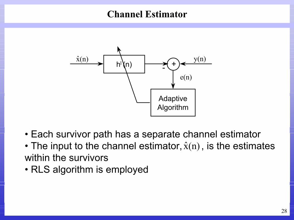
Channel Estimator
AdaptiveAlgorithm
hl (n)(n)x +
y(n)-
e(n)
• Each survivor path has a separate channel estimator• The input to the channel estimator, , is the estimates within the survivors• RLS algorithm is employed
(n)x

29
Channel Estimator
• Initial channel estimate is based on the correlation of the preamble• RLS algorithm is employed to track the channel
• Noise variance estimate:
)(ξ)(ˆ)()1()())(ˆ)1(()()(ξ
))1()(ˆ)()1((λ)()(ˆ)1()(ˆλ
)(ˆ)1()(
1-
nnnnnnnnyn
nnnnnnnn
nnn
H
H
H
∗+−=
−−=
−−−=
−+−
=
xPwwxw
PxkPPxPx
xPk
222 )(ξλ)1()1(λσ)(σ nnn −+−=

30
Experimental Results
DFE results for transducer 7.Eye Pattern - Filter coefficients
PLL phase estimate - Bit error distribution
Channel impulse response estimate for transducer seven
obtained using the channel probe

31
Experimental Results
Comparison of received signal with the estimated received signal based on the
channel estimate
Channel impulse response estimate for transducer seven
obtained using adaptive channel estimator

32
Experimental Results
• Sparse Channel with multipath delay in the order of 200 symbols• Length of the DFE or channel estimator filters cannot cover the channel• Sparse processing is needed

33
Results of DFE Turbo Decoder
Event Modulation DFE Iter1
Iter2
Iter3
Iter4
Iter5
0 QPSK 334 25 4 3 3 3BPSK 70 0
1 QPSK 488 80 56 49 47 49BPSK 22 0
2 QPSK 392 43 18 15 15 15BPSK 64 4 2 2
3 QPSK 374 27 17 12 11 11BPSK 51 0
4 QPSK 290 11 7 7 7 7BPSK 38 0
5 QPSK 121 2 0BPSK 20 0
6 QPSK 165 1 2 2 2 2BPSK 7 0
7 QPSK 247 6 2 2 2 2BPSK 1 0
8 QPSK 207 7 1BPSK 17 1 0

34
Results of Iterative DFE Turbo Decoder
Event Mod. DFE Iter1 Iter2 DFE Iter1 Iter2 DFE Iter1 Iter2 DFE Iter1 Iter2 DFE Iter1 Iter20 QPSK 334 25 4 140 1 2 133 1 1 138 1 1 139 1 11 QPSK 488 80 56 203 16 9 179 8 5 171 7 4 172 5 42 QPSK 392 43 18 186 7 7 177 6 6 173 6 6 173 6 63 QPSK 374 27 17 165 5 6 148 2 04 QPSK 290 11 7 139 5 5 131 3 3 129 3 3 129 3 35 QPSK 121 2 06 QPSK 165 1 2 73 1 1 75 2 07 QPSK 247 6 2 104 08 QPSK 207 7 1 89 0

35
Results of Iterative DFE MAP Decoder
Event Mod. DFE1 MAP1
DFE2 MAP2
DFE3 MAP3
DFE4 MAP4
DFE5 MAP5
DFE6 MAP6
0 QPSK 512 136 268 49 215 31 212 31 210 31 210 31/16BPSK 46 0
1 QPSK 307 0BPSK 40 0
2 QPSK 522 167 265 13 210 0BPSK 42 0
3 QPSK 288 40 155 5 144 5 146 5 146 5 146 5/2BPSK 47 0
4 QPSK 238 5 119 0BPSK 36 0
5 QPSK 153 0BPSK 10 0
6 QPSK 208 9 81 0BPSK 6 0
7 QPSK 91 0BPSK 7 0
8 QPSK 282 15 109 5 101 0BPSK 16 0

36
Results for Iterative Map Equalizer Turbo Decoder
PK#
MOD. EquMap1
TurIter1
TurIter2
EquMap2
TurIter1
TurIter2
EquMap3
TurIter1
TurIter2
EquMap4
TurIter1
TurIter2
EquMap5
TurIter1
TurIter2
0 BPSK 21 00 QPSK 447 73 50 80 3 3 8 01 BPSK 7 01 QPSK 682 241 222 444 154 115 197 38 25 33 4 1 3 3 02 BPSK 8 02 QPSK 427 64 45 76 1 3 6 03 BPSK 14 03 QPSK 392 59 35 62 2 1 2 04 BPSK 16 04 QPSK 313 14 6 10 05 BPSK 05 QPSK 34 1 06 BPSK 2 06 QPSK 81 1 1 3 07 BPSK 07 QPSK 52 08 BPSK 4 08 QPSK 130 2 2 6 1 1 4 1 1 4 1 1 4 1 1

37
Results for Iterative MAP Equalizer MAP Decoder
PK#
MOD. EquMAP 1
DecMAP 1
EquMAP 2
DecMAP 2
EquMAP 3
DecMAP 3
0 BPSK 13 00 QPSK 600 333 212 38 29 01 BPSK 10 01 QPSK 407 88 33 02 BPSK 7 02 QPSK 643 415 313 95 32 03 BPSK 20 03 QPSK 294 9 6 04 BPSK 18 04 QPSK 327 34 19 05 BPSK 1 05 QPSK 85 06 BPSK 8 06 QPSK 113 07 BPSK 2 07 QPSK 77 08 BPSK 2 08 QPSK 277 14 1 0

38
Conclusions
• Due to error propagation in the DFE, turbo decoder cannot provide performance improvement beyond the second iteration ⇒ Error Floor
• Joint DFE and turbo decoding adds an additional loop to the system and lowers the error floor
• Joint channel estimator and iterative equalizer is able to decode packets with low SNR, which cannot be decoded with the DFE
• Tail cancellation is an effective way to reduce the computational complexity of the MAP equalizer
• If the channel is sparse, although the DFE filter lengths are short, the DFE is able to provide enough information to the turbo decoder
• A sparse DFE can be used to improve the performance of the DFE/MAP Decoder and the DFE/Turbo Decoder

39
References
[1] S. Benedetto, et.al., “Serial concatenation of interleaved codes: Design and performance analysis,” IEEE Trans. Info. Theory, vol. 42, pp. 409-429, April 1998[2] I. Lee, “The effect of a precoder on serially concatenated coding systems with ISI channel,” IEEE Trans. Commun., pp. 1168-1175, July 2001[3] C. Douilard, et.al., “Iterative correction of intersymbol interference: Turbo-equalization,” European Transactions on Telecommunications, vol. 6, pp. 507-511, Sep.-Oct. 1995[4] G. Bauch, H. Khorram, and J. Hagenauer, “Iterative equalization and decoding in mobile communications systems,” in Proc. European Personal Mobile Commun. Conf., pp. 307-312[5] J. Proakis, Digital Communications, McGraw-Hill Inc., 2001[6] M. Tuchler, A. Singer, and R. Koetter, “Minimum mean squared error equalization using a priori information,” IEEE Trans. Signal Proc., vol. 50, pp. 673-683, March 2002