item #11737 master blaster dual blaster - eastwood · to order parts and supplies: 800.345.1178...
TRANSCRIPT

MASTER BLASTERDUAL BLASTER
INSTRUCTIONS
Item #11737

2 Eastwood Technical Assistance: 800.544.5118 >> [email protected]
Eastwood Dual Blaster allows you to strip, clean and blast with our specially designed “mixing valve” to instantly switch from Soda Media to Abrasive and back again in seconds.
Before attempting to operate your new blaster, please read these instructions thoroughly. You will need these instructions for the safety warnings, precautions, assembly, operation, maintenance procedures, parts list, diagrams, and troubleshooting.
The warnings, cautions and instructions discussed in this instruction manual cannot cover all possible conditions or situations that could occur. It must be understood by the operator that a certain level of expertise is required before attempting to operate this equipment.
SPECIFICATIONS Tank Volume (2X) 10 gallons / 100 lbs. abrasive or 75 lbs. of soda media.
Hose Length 8 ft. x 1/2" i.d.
Working Pressure 60-125 psi
Air Consumption 6-25 cfm

To order parts and supplies: 800.345.1178 >> eastwood.com 3
WARNING indicates a hazardous situation which, if not avoided, will result in death or serious injury.
SAFETY INFORMATION
READ INSTRUCTIONS Thoroughly read and understand this manual before using the Eastwood Dual Blaster. Save for future reference.
HEALTH HAZARD• Silica based abrasives have been linked to severe respiratory disease. Do not use sand or silica based abrasives with this blaster.
• The dust produced by abrasive blasting can contain hazardous materials such as lead, zinc chromate, cadmium, and other toxic compounds depending on the substrate being blasted. Always wear a NIOSH approved breathing apparatus when abrasive blasting.
• Never operate the abrasive blaster indoors.
SEVERE INJURY - ABRASIVE SPRAY• The abrasive blast stream from this unit can cause severe eye injury and blindness. Severe skin abrasion and fl esh removal can quickly occur from
exposure to the blast stream.
• Eye protection must be worn at all times when using the Abrasive Blaster. Use ANSI approved safety glasses at all times, even when using a blast hood.
• Wear heavy, abrasive-resistant rubber blasting gloves to protect hands and forearms from abrasive injury.
SHOCK HAZARD• Under certain conditions (low humidity and certain types of blast media) the friction of abrasive blasting can generate a static
electricity charge resulting in signifi cant static shocks.
BURSTING HAZARD• Air inlet pressure must not exceed 125 psi. Excessive air pressure can cause the unit to burst causing personal injury and
damage to property.
AIR SUPPLY HAZARD• Install a ball valve in the supply line so that air can be shut off quickly in an emergency.
• Always disconnect the air supply and release pressure from the tanks before refi lling with media, storing, servicing, or changing accessories.
• Discharge the tool in a safe fashion after the air supply is shut off to ensure that all residual air is bled from the tank and hoses.
• To prevent injury from accidental operation, do not install a female quick connect coupling to the blaster. Such couplers contain a valve that shuts off automatically upon disconnection and allows the air tanks to remain charged after they are disconnected from the air supply.
• Check for damage or wear regularly and replace any worn or damaged parts before use.
• Always check to make sure the dead man valve is closed before connecting the air supply to the blaster.
• Never use oxygen, carbon dioxide, combustible gasses, or any other bottled gas to operate this tool. These gasses work at pressures capable of bursting this tool’s tanks, or are explosive and fl ammable.
4 Eastwood Technical Assistance: 800.544.5118 >> [email protected]
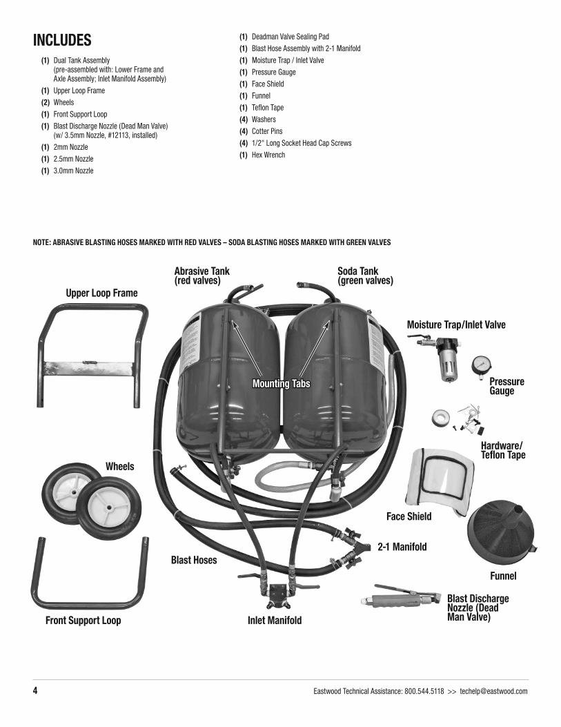
Upper Loop Frame
Wheels
Front Support Loop
Abrasive Tank(red valves)
Inlet Manifold
Soda Tank(green valves)
Blast Hoses2-1 Manifold
Moisture Trap/Inlet Valve
Pressure Gauge
Hardware/Tefl on Tape
Funnel
Face Shield
Blast Discharge Nozzle (Dead Man Valve)
Mounting TabsMounting Tabs
NOTE: ABRASIVE BLASTING HOSES MARKED WITH RED VALVES – SODA BLASTING HOSES MARKED WITH GREEN VALVES
INCLUDES (1) Dual Tank Assembly
(pre-assembled with: Lower Frame and Axle Assembly; Inlet Manifold Assembly)
(1) Upper Loop Frame
(2) Wheels
(1) Front Support Loop
(1) Blast Discharge Nozzle (Dead Man Valve) (w/ 3.5mm Nozzle, #12113, installed)
(1) 2mm Nozzle
(1) 2.5mm Nozzle
(1) 3.0mm Nozzle
(1) Deadman Valve Sealing Pad
(1) Blast Hose Assembly with 2-1 Manifold
(1) Moisture Trap / Inlet Valve
(1) Pressure Gauge
(1) Face Shield
(1) Funnel
(1) Tefl on Tape
(4) Washers
(4) Cotter Pins
(4) 1/2" Long Socket Head Cap Screws
(1) Hex Wrench

To order parts and supplies: 800.345.1178 >> eastwood.com 5
STEP 5STEP 5STEP 4STEP 4
STEP 7STEP 7STEP 6STEP 6
STEP 8STEP 8
STEPS 11-12STEPS 11-12 STEP 13STEP 13
ASSEMBLY1. Remove Dual-Tank Assembly from container and place on a soft work
surface for assembly.
2. To assemble Upper Loop Frame to Lower Frame and Axle Assembly: Locate the two 1-1/4” long Phillips head screws and nuts attaching the upper, outward curved mounting tabs of the two tanks to the Lower Frame and Axle Assembly. Remove and retain the two Phillips head screws and nuts. Place the tubular sides of the Upper Loop Frame over the swaged ends of the Lower Frame and Axle Assembly. Re-attach this assembly to the 2 outward curved tank mounting tabs with the 1-1/4” long Phillips head screws and nuts.
3. Install the 2 wheels, with offset hubs inward, onto axle ends with wash-ers on both the inboard and outboard sides. Push Cotter Pins through holes in axle and bend split ends around axle.
4. Slide the Front Support Loop over the leg stubs welded to the front of the tanks. Place a cotter pin in each hole and fold split ends over.
5. Attach Inlet Manifold to the tab on the crossmember of the Frame As-sembly with 4 included 1/2” long socket head cap screws.
6. Using Tefl on Tape, thread the Pressure Gauge into the open port on the top of the Inlet Manifold and tighten. CAUTION: these are tapered pipe threads and over tightening will cause permanent damage.
7. Using Tefl on Tape, thread the Moisture Trap and Inlet Valve into the rear facing port of the Inlet Manifold and tighten. CAUTION: these are tapered pipe threads and over tightening will cause permanent damage. IMPORTANT NOTE: The Eastwood Dual Blaster combines two separate blasting systems using one Discharge Nozzle. The Soda System is identifi ed with GREEN valves while the Abrasive System is identifi ed with RED valves. When viewed from the back (wheel side) the RED (Abrasive) is on the LEFT and the GREEN (Soda) is on the RIGHT. When making hose connections, it is vitally important to keep the systems as designated.
8. Using Tefl on Tape, thread the female fi tting of the right (SODA) pres-sure hose into the right front male fi tting on the Inlet Manifold and tighten. CAUTION: these are tapered pipe threads and over tightening will cause permanent damage.
9. Repeat previous step for the left (ABRASIVE) pressure hose.
10. To provide access to the manifold assemblies on the underside of the tanks, gently lay the unit on its back using one of the foam packing blocks, or other suitable object for support to keep the Moisture Trap and Inlet Valve from hitting the fl oor.
11. Attach the right side SODA blast hose (GREEN VALVE) to the barbed fi tting and securely tighten the hose clamp. NOTE: Be certain that the GREEN VALVE at the tank end corresponds to the GREEN VALVE at the Discharge Nozzle end.
12. Repeat previous step for the left (ABRASIVE) blast hose.
13. Using Tefl on Tape, thread the Blast Discharge Nozzle to the 2-in-1 Manifold. CAUTION: these are tapered pipe threads and over tighten-ing will cause permanent damage.
STEP 3STEP 3STEP 2STEP 2

6 Eastwood Technical Assistance: 800.544.5118 >> [email protected]
BEFORE BEGINNINGBefore beginning any blasting, the separate Soda Blasting and Abrasive Blasting systems must be individually adjusted for optimal fl ow. Failure to do so will result in ineffi cient operation and wasted media. This manual is divided into two sections, Blasting With Soda and Blasting with Abrasive Media. Please follow the individual following procedures for Soda Blasting (GREEN SIDE) and Abrasive Blasting (RED SIDE).
SODA BLASTING (GREEN VALVES)Although the Bicarbonate of Soda (Baking Soda) blasting media itself is safe in most situations, appropriate care should be taken when using or disposing as some removed paints and coatings may contain some levels of hazardous materials such as lead, zinc chromate, etc. Additional protection may be required in the presence of these substances.
Soda Blasting Media is highly susceptible to moisture absorption which will cause clumping and erratic operation. To insure proper function, it is imperative to have an effective moisture fi lter and or desiccant system in the air supply immediately before the Air Inlet. Be sure to drain any moisture captured in the moisture fi lter before and after each use. Failure to do so may cause “caking” of media and complete blockage of equipment.
SODA OPERATION1. Carefully fi ll the unit per Blaster Instructions using a screen sifter and funnel.
NOTE: a suitable screen sifter such as Eastwood #50417 Sifter/Funnel must be used to capture any clumps present in the bag of media.
2. Close all four valves and connect the air supply. DO NOT EXCEED 125 PSI. For best results, begin with a blaster inlet pressure of 80 to 90 PSI. To avoid media clumping or caking, be certain to have a clean, moisture free air supply that includes an effective moisture fi lter or desiccant system.
3. Open the Inlet Air Supply Valve slowly and carefully while checking for leakage.
4. Slowly open the Throttling Valve (FIG. 1) to the 1⁄2 position while checking for leakage. NOTE: This valve will require fi ne tuning to provide optimal media fl ow based on media formulation, air pressure and desired volume.
5. Slowly open the Media Flow Valve (FIG. 2) to the full position while checking for leakage.
6. You may now direct the nozzle toward your work and depress the Nozzle Discharge Lever. NOTE: Some slow, pulsing discharges of media can be expected until the fl ow begins.
7. Once a steady fl ow of media is observed, begin by holding the nozzle 6” to 12” from the work surface at a 30°-45° angle for best results.
8. Hold the stream against the work until it abrades through the coating revealing an edge.
9. Use the stream as a “wedge” working at the edge to quickly remove the coating.
10. At this point you can vary the position of the Throttling Valve (FIG. 1) from the initial 1⁄2 open starting setting to achieve an optimum air/media ratio. NOTE: As there are many variables affecting the fl ow such as media formulation, hardness of coating, air volume, air pressure and atmospheric conditions, this process requires a bit of “trial and error” by experimenting with distance, angle and throttle position. You will quickly become profi cient at determining the ideal settings.
11. When refi lling the tank becomes necessary, fi rst shut off the Inlet Air Supply Valve, The Throttling Valve and The Flow Valve. For safety, disconnect the air supply. Next, open the Purge Valve to release all tank pressure. You may then open the Tank Filler Cap and refi ll following the procedure in step 1.
12. All unused media MUST be drained from the tank when completing work as any moisture present in the tank will drain to the bottom of the tank and can create a solid “cake” with the media, requiring complete disassembly of the apparatus at the bottom of the tank. NOTE: Failure to properly seal or over tightening fi ttings can lead to component failure which could result in sudden air pressure release and cause serious injury.
13. To drain unused media from the tank, place the open end of The Clear Purge Hose into a suitable container such as a large bucket or sturdy box with closed seams and cover with a blanket. Using extreme care, slowly open the Purge Valve and direct the stream of media into the container.
Throttle Valve (shown in halfway position)
FIG 1FIG 1
FIG 2FIG 2
Media Flow ValveMedia Flow Valve
Purge ValvePurge Valve

To order parts and supplies: 800.345.1178 >> eastwood.com 7
TROUBLESHOOTING SODA BLASTING1. The most common problem encountered with Soda Blasting is clumping of media due to moisture contamination. If media stops fl owing, stop all work and “burp” (quickly
open and close) the Purge Valve allowing a minimal discharge of media from the Clear Purge Hose. Be certain to direct the discharge to a safe area. Placement of the hose in a cardboard box covered with a blanket is strongly recommended.
2. If a purge fails to restore fl ow, stop all work and close the Throttle Valve fully. You can then depress the Nozzle Discharge Lever several times which will discharge a quan-tity of media under tank pressure clearing the clumping.
3. It is strongly advisable to drain all unused media when completing work as any moisture present in the tank will drain to the bottom of the tank and can create a solid “cake” with the media. Should this occur, it will require complete disassembly of the apparatus at the bottom of the tank for cleaning.
4. If results become erratic or undesirable, remember that there are many variables affecting the fl ow such as media formulation, hardness of coating, air volume, air pres-sure and atmospheric conditions. This process requires some “trial and error” by experimenting with distance, angle and throttle position. By adjusting the Throttle Valve position (FIG. 1) between 1⁄2 and full open and varying the distance, and angle of the nozzle to work surface, optimal performance can quickly be restored. Refer to steps 8 through 11 in the Operation section for the procedure.
WORK AREA PREP & CLEANUP1. Soda Blasting generates a considerable amount of fi ne bicarbonate of soda dust. If working outdoors, be aware of wind direction, open windows, vegetation, vehicles,
pets, people and property. It may be helpful to place a fi ne mist, garden hose lawn sprinkler downwind of the blasting site to suppress dust generation.
2. It is best to cover the work area under and surrounding the vehicle or object to be stripped with a 3 mil or thicker plastic sheet material to assist in cleanup. You may also wish to tape up window seals and other areas to keep unwanted dust out of a vehicle.
3. Bicarbonate of Soda itself is virtually harmless to the environment however, in higher concentrations; it may cause browning of vegetation. Care should be taken to avoid depositing excess soda on plant life.
4. When fi nished, the plastic sheeting with the used soda media can be rolled up and disposed of, reducing sweep up time. The remainder should be swept up and disposed of. Any remaining soda residue is water soluble and can be hosed away. IMPORTANT NOTE: Although the Bicarbonate of Soda blasting media itself is safe in most situations, appropriate care should be taken when using or disposing as any removed paint or coating can contain some levels of hazardous materials such as lead, zinc chromate, etc.
HELPFUL TIPS• Soda Blasting leaves behind a thin protective fi lm which, if left untouched, will prevent surface rust from forming on bare steel surfaces for up 6 weeks or even longer if
stored in a dry, protected area. This fi lm must be removed before painting by wiping down with acetone dampened Microfi ber cloths or suitable lint-free towels. Only use acetone to wipe residue. Wipe off soda residue, rinse often and immediately follow up with a dry lint-free towel.
• Any soda media left in body seems or crevices can be removed with a small shop vacuum and a fi ne tipped blow gun. Be sure to wipe surrounding areas as described above.
• To prevent fl ash rust or oxidation from appearing on metal surfaces after water wipe down but before painting, treat surfaces with Eastwood Fast-Etch™ #19416Z.
SODA BLASTING AIR SUPPLY AND MEDIA CONSUMPTIONThis data is approximate and is presented for comparison use. Due to the many variables such as; compressor capacity, air line size, grade and grit size of media used, coating thickness and hardness, individual results will vary.
Nozzle Size CFM @ 80 PSI Approx. Media Usage Area
2mm 6 25 lbs/hr 135 sq. in/hr
2.5mm 12 35 lbs/hr 180 sq. in/hr
3mm 20 60 lbs/hr 250 sq. in/hr
3.5mm 25 75 lbs/hr 425 sq. in/hr

8 Eastwood Technical Assistance: 800.544.5118 >> [email protected]
ABRASIVE BLASTING (RED VALVES) Always wear your blast hood, NIOSH approved respiratory protection, ANSI-approved safety glasses and heavy duty canvas gloves when operating the abrasive blaster.
Before operating your abrasive blaster, inspect each connection, double checking to make sure that all are tight and properly sealed.
THIS MACHINE IS NOT INTENDED FOR USE WITH SILICA BASED ABRASIVES. SILICA BASED ABRASIVES HAVE BEEN LINKED TO SEVERE RESPIRATORY DISEASE.
LOADING ABRASIVE1. Before opening tank, be sure that it is not pressurized and the air gauge reads “0”.
2. To release the pressure from the Tank, press Blast Discharge Nozzle until air stops.
3. Check to make sure the abrasive is dry and clean so that it does not clog the unit. Use 80 grit or fi ner material.
4. Close the brass Air Supply Valve by turning it to the vertical position.
5. Remove the Filler Cap.
6. Using the Funnel, pour the selected abrasive media into the tank. Do not fi ll the tank more than 3/4 full. If humidity in your region is 90% or more, only fi ll the tank half full and check the water trap more frequently.
7. Close the Filler Cap securely, assuring o-ring is in place.
8. To avoid damage, it is advisable to have your compressor located in another room away from damaging debris.
TO START ABRASIVE BLASTINGStart with all valves in the closed position. Following the instructions below will help prevent the formation of clogs in the abrasive hose, outlet manifold and the Blast Discharge Nozzle.
1. Connect air compressor to the Inlet Connector.
2. Open Air Supply Valve.
3. Open Throttling Valve.
4. Check for leaks at the Filler Cap and along all hoses and fi ttings as the system pressurizes. If leaks are observed, release the pressure from the tank and repair immedi-ately.
5. Point Blast Discharge Nozzle in a safe direction away from people, pets or anything around you that may be harmed by direct or indirect abrasive spray.
6. Press and hold Blast Discharge Nozzle until air is fl owing through the nozzle.
7. With the Blast Discharge Nozzle open, slowly open the Abrasive Control Valve until abrasive material begins to fl ow out of the Blast Discharge Nozzle.
8. Abrasive Flow Adjustment as follows: NOTE: The Abrasive Flow is a fi nely tuned combination of two adjustments which can vary with different media and atmospheric conditions.
- Adjust air pressure with the Throttling Valve. The Throttling Valve controls the velocity of material flow. - Adjust abrasive flow with Abrasive Control Valve. The Abrasive Control Valve controls the amount of abrasive in the stream. - Watch for abrasive clogging. Release pressure from the tank if necessary and replace the abrasive with drier or cleaner abrasive.
9. Begin blasting.
TO STOP BLASTING1. While continuing to press and hold the Blast Discharge Nozzle, turn the Abrasive Control Valve to the closed position (this is to prevent any clogging.)
2. When you notice only air (no abrasive) is coming out of the Blast Discharge Nozzle, you can stop the air fl ow by releasing the trigger. This ensures a clean and clog-free manifold, hose, and safety trigger.

To order parts and supplies: 800.345.1178 >> eastwood.com 9
RELEASING PRESSURE FROM THE TANK1. When you are fi nished blasting, point Blast Discharge Nozzle in a safe direction away from people, pets or anything around you that may be harmed by direct or indirect
abrasive spray.
2. Press and hold the Blast Discharge Nozzle to expel any remaining abrasive material from the Abrasive Hose.
3. Close the Abrasive Control Valve.
4. Release pressure on the Blast Discharge Nozzle.
5. Close the Throttling Valve and the Air Supply Valve.
6. Disconnect air supply hose from abrasive blaster.
7. Press the Blast Discharge Nozzle until air stops fl owing and Pressure Gauge reads “0”.
Pay particular attention to the Abrasive Hose, the Abrasive Control Valve, and the Nozzles as they will wear out much more quickly than the other pieces.
The Abrasive Hose needs to be replaced immediately if its side walls develop leaks or show blisters in the surface. Do not use if any of these problems are present.
ABRASIVE SELECTIONThe kind of abrasive you choose will greatly infl uence the amount of time needed to clean a given surface area. Abrasive materials include glass beads, aluminum oxide, and oth-ers. For best results, use 80 grit abrasive or fi ner. Do not exceed 80 grit media size.
• Make sure that the abrasive you use is thoroughly dry. Damp abrasive can cause clogging of your abrasive blaster.
• While you may reuse abrasive, remember that abrasive does wear out. After use, abrasive becomes smoother and rounder, thus reducing abrasive effectiveness.
• Reusing abrasive may also cause clogging due to debris contained in the mixture from prior use.
ABRASIVE BLASTING SUPPLY REQUIREMENTS
Hose Inside Diameter Hose Length Nozzle ID Approx. Compressor HP CFM @ 125 psi Abrasive Use/Hr
3/8" 50' 2mm 2 6 30 lbs.
3/8" 25' 2.5mm 4 12 80 lbs.
1/2" 50' 3mm 7 20 120 lbs.
1-1/2" 15' 3.5mm 10 25 150 lbs.

10 Eastwood Technical Assistance: 800.544.5118 >> [email protected]
MAINTENANCE 1. Keep your Eastwood Dual Blaster clean, and protect it from damage.
2. Release pressure from the tank after each use.
3. When initially pressurizing, check for leaks at the tank top and at all hoses and fi ttings. Leaking joints may be repaired by replacing worn or damaged parts and using tefl on tape at joints.
4. Check for worn abrasive hose and fi ttings. The Abrasive Control Valve, manifold, and all parts after the abrasive is ejected from the tank are subject to rapid wear due to the fl ow of abrasive. Watch especially for leaks, blistering, bulging or thinness of the hose. Replace any parts which appear worn.
Full Soda – No Abrasive Infi nite Mix Between Soda/Abrasive
Full Abrasive – No Soda
GREEN VALVE fully open
RED VALVE fully
closed
GREEN VALVE
partially open
RED VALVE
partially open
GREEN VALVE fully
closed
RED VALVE fully open
SWITCHING BETWEEN SODA (GREEN) & ABRASIVE (RED)1. Release Blast Discharge Nozzle shutting off the media fl ow.
2. Close Soda Valve (Green) and open Abrasive Media (Red) to switch from Soda to Abrasive.
3. Depress Safety Trigger allowing fl ow although the opposite media will continue to fl ow until the hose has cleared.

To order parts and supplies: 800.345.1178 >> eastwood.com 11
WARRANTYThis product has a one year warranty covering any manufacturing defects. Despite our strict quality control standards implemented during our manufacturing process, sometimes a product gets shipped that does not meet our specifi cations. If you have a product that does not work correctly, you must contact the Eastwood Company at 800-345-1178 to acquire a Return Authorization Number.
ACCESSORIES#22022 Blast Media Sifter Screen
#22122 Hardware Basket for Abrasive Blasting
#50417 Abrasive Media Funnel Strainer
#22095 Deluxe Abrasive Blasting Hood
#14838 Half Mask Respirator
#14844 Full Mask Respirator
MEDIA#11806 50lb Basic Soda Blast Media
#11807 50lb XL Soda Blast Media
#22023 50lb Glass Bead Media, 70-100 Grit
#13772 50lb Glass Bead Media, 100-170 Grit
#22021 50lb Aluminum Oxide Media

© Copyright 2015 Easthill Group, Inc. 6/15 Instruction #11737Q Rev 0
If you have any questions about the use of this product, please contact The Eastwood Technical Assistance Service Department: 800.544.5118 >> email: [email protected]
PDF version of this manual is available online >> eastwood.com/11737manual
The Eastwood Company 263 Shoemaker Road, Pottstown, PA 19464, USAUS and Canada: 800.345.1178 Outside US: 610.718.8335
Fax: 610.323.6268 eastwood.com
NOTES