item #0507171a -hydrodynamic separator work also includes the preparation of hydraulic design...
TRANSCRIPT

Rev. Date 04/2010
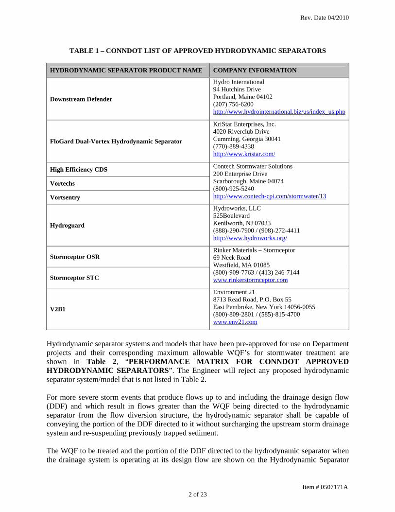
ITEM #0507171A -HYDRODYNAMIC SEPARATOR Description: Hydrodynamic separators are proprietary devices manufactured for stormwater treatment. The hydrodynamic separator shall be a precast concrete structure and include an internal chamber with features that induce a swirling, circular, or spiraling flow pattern in the stormwater flow that separate and trap sediment and pollutants in a chamber that can be accessed for later removal. This item will consist of furnishing and construction of a hydrodynamic separator, a flow diversion structure, manholes and pipes in the location, grades, treatment capacity and to the dimensions and details shown on the contract drawings, and in accordance with these specifications or as directed by the Engineer. The work also includes the preparation of hydraulic design calculations for the hydrodynamic separator(s) and flow diversion structure(s) as specified herein. The hydrodynamic separator shall be assembled and installed in strict compliance with the Manufacturer’s instructions unless otherwise directed by these specifications or by the Engineer. Internal flow controls / diversion components, external appurtenances, concrete manhole riser sections, manhole frames and covers, reinforcing, threaded inserts, lifting and seating fixtures, non-shrink grout, and all other necessary materials and equipment to complete the work shall be included. This item shall also include the cleaning of the hydrodynamic separator of all sediment and debris every 90 days, or as needed, from when they are put into service, until final acceptance of the project. Approved Products and Manufacturer Information: Proprietary hydrodynamic separators currently approved by the Department are listed in Table 1 “CONNDOT LIST OF APPROVED HYDRODYNAMIC SEPARATORS”. Company contact information is provided for convenience. As the company information frequently changes, the Department is not responsible for its accuracy. The Engineer will reject any proposed hydrodynamic separator that is not listed in Table 1. The listed products have been approved for use on Department projects based on only a general review of the product’s construction, function and treatment capabilities. Therefore, the approved list shall not be construed to mean that all products appearing on the list are suitable to any specific project site or drainage design. Performance: The stormwater treatment performance of the selected hydrodynamic separator shall be based on the water quality flow (WQF) as defined and calculated in accordance with the Department’s current version of the Drainage Manual. The hydrodynamic separator shall be designed to treat the entire WQF as indicated on the contract drawings or specifications, without bypass, either through the separator’s internal components or at the flow diversion structure.
Item # 0507171A 1 of 23
Rev. Date 04/2010
TABLE 1 – CONNDOT LIST OF APPROVED HYDRODYNAMIC SEPARATORS
HYDRODYNAMIC SEPARATOR PRODUCT NAME COMPANY INFORMATION
Downstream Defender
Hydro International 94 Hutchins Drive Portland, Maine 04102 (207) 756-6200 http://www.hydrointernational.biz/us/index_us.php
FloGard Dual-Vortex Hydrodynamic Separator
KriStar Enterprises, Inc. 4020 Riverclub Drive Cumming, Georgia 30041 (770)-889-4338 http://www.kristar.com/
High Efficiency CDS
Vortechs
Vortsentry
Contech Stormwater Solutions 200 Enterprise Drive Scarborough, Maine 04074 (800)-925-5240 http://www.contech-cpi.com/stormwater/13
Hydroguard
Hydroworks, LLC 525Boulevard Kenilworth, NJ 07033 (888)-290-7900 / (908)-272-4411 http://www.hydroworks.org/
Stormceptor OSR
Stormceptor STC
Rinker Materials – Stormceptor 69 Neck Road Westfield, MA 01085 (800)-909-7763 / (413) 246-7144 www.rinkerstormceptor.com
V2B1
Environment 21 8713 Read Road, P.O. Box 55 East Pembroke, New York 14056-0055 (800)-809-2801 / (585)-815-4700 www.env21.com
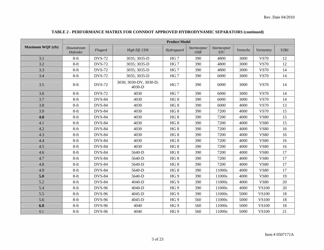
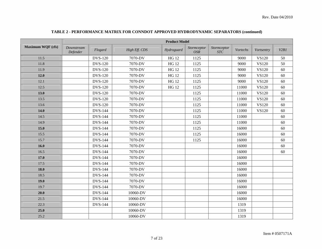
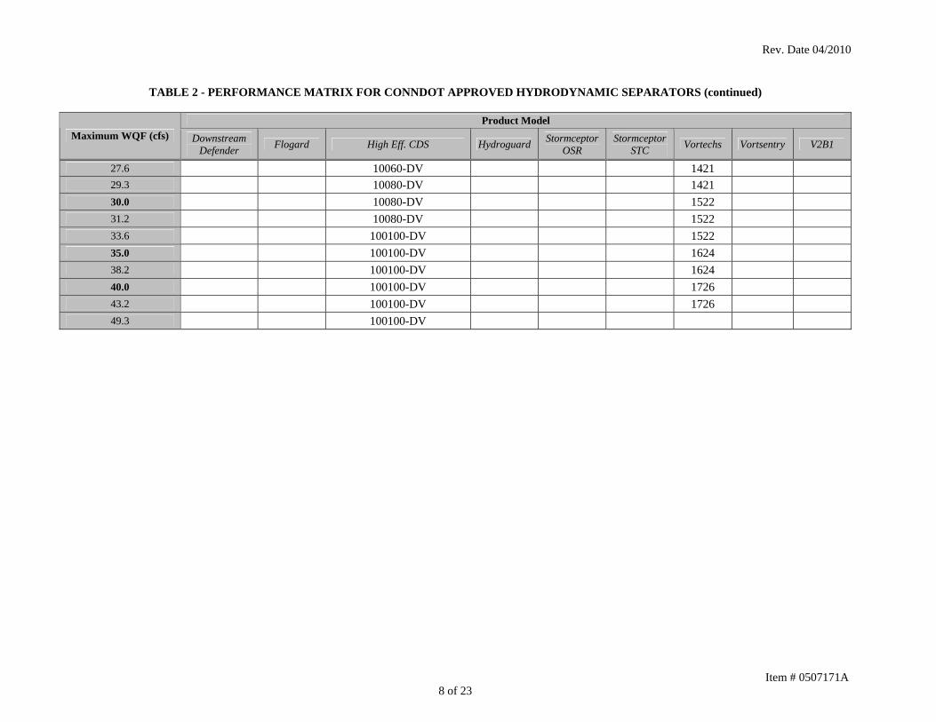
Hydrodynamic separator systems and models that have been pre-approved for use on Department projects and their corresponding maximum allowable WQF’s for stormwater treatment are shown in Table 2, “PERFORMANCE MATRIX FOR CONNDOT APPROVED HYDRODYNAMIC SEPARATORS”. The Engineer will reject any proposed hydrodynamic separator system/model that is not listed in Table 2. For more severe storm events that produce flows up to and including the drainage design flow (DDF) and which result in flows greater than the WQF being directed to the hydrodynamic separator from the flow diversion structure, the hydrodynamic separator shall be capable of conveying the portion of the DDF directed to it without surcharging the upstream storm drainage system and re-suspending previously trapped sediment. The WQF to be treated and the portion of the DDF directed to the hydrodynamic separator when the drainage system is operating at its design flow are shown on the Hydrodynamic Separator
Item # 0507171A 2 of 23

Rev. Date 04/2010
Item # 0507171A 3 of 23
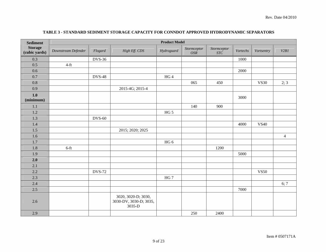
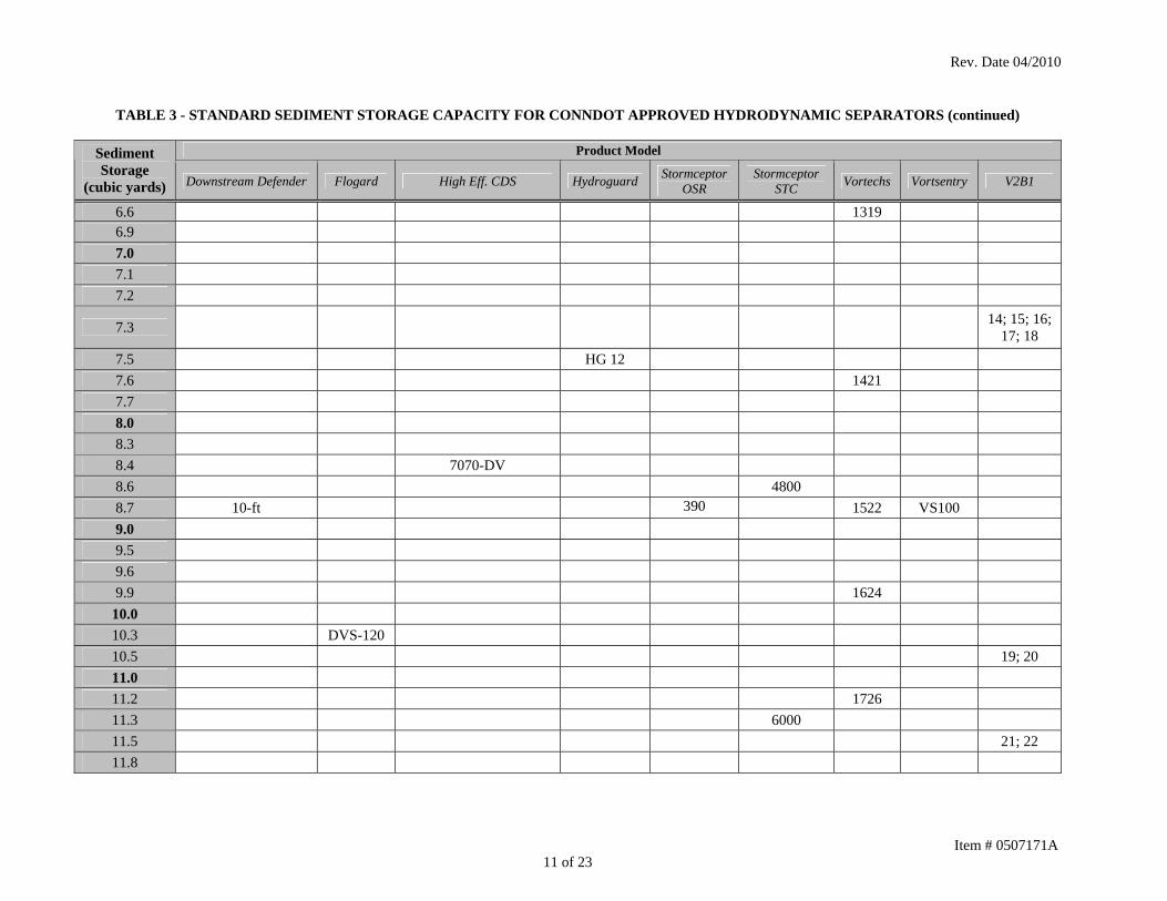
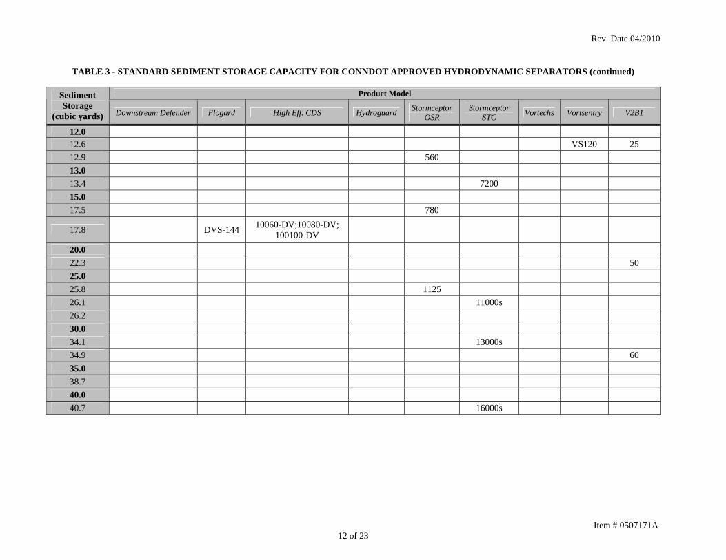
Design Data Sheets (Form A - Design). A separate form for each hydrodynamic separator site on the project is attached to this specification. Sediment Storage Capacity: Settleable solids shall accumulate in a location within the hydrodynamic separator structure that is accessible for cleaning and maintenance but not susceptible to resuspension. Direct access through openings in the precast concrete unit shall be provided to the sediment storage chamber and all other chambers to facilitate maintenance. The standard sediment storage capacities for Department pre-approved hydrodynamic separator systems/models are shown in Table 3, “STANDARD SEDIMENT STORAGE CAPACITY FOR CONNDOT APPROVED HYDRODYNAMIC SEPARATORS”. The sediment storage capacities listed in Table 3 are values based on standard structure dimensions and anticipated maintenance requirements. Some standard hydrodynamic separator models may be modified as determined by the Manufacturer to increase the sediment storage capacity. When a modification is proposed by increasing the depth of the standard structure, the sediment storage capacity of the proposed structure shall be determined in accordance with Table 4, “SEDIMENT STORAGE CAPACITY CALCULATION”. The Contractor shall be responsible for verifying the standard sediment storage capacity of the hydrodynamic separator unit(s) and coordinating any proposed modifications to increase sediment storage capacity with the Manufacturer(s). All proposed modifications and revised sediment storage capacity determinations shall be clearly documented in the working drawing submission to the Department. The minimum sediment storage capacities required for each hydrodynamic separator site on the project are shown on the Hydrodynamic Separator Design Data Sheets (Form A – Design) attached to this specification. Hydraulic Design: The Contractor shall prepare or have prepared a hydraulic grade line (HGL) analysis for an evaluation of the selected hydrodynamic separator and the design of the flow diversion structure as described in this section. The HGL analysis shall be performed for both the WQF and the DDF. The analysis shall be consistent with the methodology described in Section 11.12 of the Department’s Drainage Manual. Head loss coefficients, to be used in the HGL analysis, shall be determined in accordance with Section 11.12.6 for all structures except the hydrodynamic separator, which shall be obtained from the Manufacturer. Documentation shall be submitted demonstrating how the coefficient was derived either through calculation and/or testing data. A benching factor of 1.0 shall be applied to the flow diversion structure. The HGL analysis (or portion of) that was performed for the design of the storm drainage systems and preparation of the construction plans, including the design of the flow diversion structure and evaluation of a “generic” hydrodynamic separator, is shown on the Hydrodynamic Separator Design Data Forms (Form A – Design) attached to this specification.

Rev. Date 04/2010
TABLE 2 - PERFORMANCE MATRIX FOR CONNDOT APPROVED HYDRODYNAMIC SEPARATORS
Product Model Maximum WQF (cfs) Downstream
Defender Flogard High Eff. CDS Hydroguard Stormceptor OSR
Stormceptor STC Vortechs Vortsentry V2B1
0.4 4-ft DVS-36 2015-4G; 2015-4 HG 4 065 450 1000 VS30 2 0.5 4-ft DVS-36 2015-4G; 2015-4 HG 4 065 900 1000 VS30 2 0.6 4-ft DVS-36 2015-4G; 2015-4 HG 4 065 900 1000 VS40 2 0.7 4-ft DVS-48 2015-4G; 2015-4 HG 4 140 900 1000 VS40 2 0.8 4-ft DVS-48 2015-4G; 2015-4 HG 4 140 900 1000 VS40 2 0.9 4-ft DVS-48 2015-4G; 2015-4 HG 4 140 1200 1000 VS40 3 1.0 4-ft DVS-48 2015-4G; 2015-4 HG 4 140 1800 1000 VS40 3 1.1 4-ft DVS-48 2015-4G; 2015-4 HG 4 140 1800 1000 VS40 4 1.2 6-ft DVS-48 2015 HG 5 140 2400 1000 VS50 4 1.3 6-ft DVS-60 2015 HG 5 140 2400 1000 VS50 4 1.4 6-ft DVS-60 2015 HG 5 140 2400 2000 VS50 4 1.5 6-ft DVS-60 2020 HG 5 140 2400 2000 VS50 6 1.6 6-ft DVS-60 2020 HG 5 140 2400 2000 VS50 6 1.7 6-ft DVS-60 2020 HG 5 250 2400 2000 VS50 6 1.8 6-ft DVS-60 2020 HG 6 250 2400 2000 VS50 7 1.9 6-ft DVS-60 2020 HG 6 250 3600 2000 VS60 7 2.0 6-ft DVS-60 2020 HG 6 250 3600 2000 VS60 7 2.1 6-ft DVS-60 2020 HG 6 250 3600 2000 VS60 9 2.2 6-ft DVS-72 2025 HG 6 250 3600 2000 VS60 8 2.3 6-ft DVS-72 3020, 3020-D HG 6 250 3600 2000 VS60 8 2.4 6-ft DVS-72 3035; 3035-D HG 6 250 4800 2000 VS60 8 2.5 6-ft DVS-72 3035; 3035-D HG 6 250 4800 3000 VS60 10 2.6 6-ft DVS-72 3035; 3035-D HG 6 250 4800 3000 VS60 11 2.7 6-ft DVS-72 3035; 3035-D HG 7 250 4800 3000 VS60 11 2.8 6-ft DVS-72 3035; 3035-D HG 7 250 4800 3000 VS70 11 2.9 6-ft DVS-72 3035; 3035-D HG 7 250 4800 3000 VS70 12 3.0 6-ft DVS-72 3035; 3035-D HG 7 390 4800 3000 VS70 12
Item # 0507171A 4 of 23
Rev. Date 04/2010
TABLE 2 - PERFORMANCE MATRIX FOR CONNDOT APPROVED HYDRODYNAMIC SEPARATORS (continued)
Product Model Maximum WQF (cfs) Downstream
Defender Flogard High Eff. CDS Hydroguard Stormceptor OSR
Stormceptor STC Vortechs Vortsentry V2B1
3.1 8-ft DVS-72 3035; 3035-D HG 7 390 4800 3000 VS70 12 3.2 8-ft DVS-72 3035; 3035-D HG 7 390 4800 3000 VS70 12 3.3 8-ft DVS-72 3035; 3035-D HG 7 390 4800 3000 VS70 14 3.4 8-ft DVS-72 3035; 3035-D HG 7 390 6000 3000 VS70 14
3.5 8-ft DVS-72 3030; 3030-DV, 3030-D; 4030-D HG 7 390 6000 3000 VS70 14
3.6 8-ft DVS-72 4030 HG 7 390 6000 3000 VS70 14 3.7 8-ft DVS-84 4030 HG 8 390 6000 3000 VS70 14 3.8 8-ft DVS-84 4030 HG 8 390 6000 4000 VS70 13 3.9 8-ft DVS-84 4030 HG 8 390 7200 4000 VS70 15 4.0 8-ft DVS-84 4030 HG 8 390 7200 4000 VS80 15 4.1 8-ft DVS-84 4030 HG 8 390 7200 4000 VS80 15 4.2 8-ft DVS-84 4030 HG 8 390 7200 4000 VS80 16 4.3 8-ft DVS-84 4030 HG 8 390 7200 4000 VS80 16 4.4 8-ft DVS-84 4030 HG 8 390 7200 4000 VS80 16 4.5 8-ft DVS-84 4030 HG 8 390 7200 4000 VS80 16 4.6 8-ft DVS-84 5640-D HG 8 390 7200 4000 VS80 17 4.7 8-ft DVS-84 5640-D HG 8 390 7200 4000 VS80 17 4.8 8-ft DVS-84 5640-D HG 8 390 7200 4000 VS80 17 4.9 8-ft DVS-84 5640-D HG 8 390 11000s 4000 VS80 17 5.0 8-ft DVS-84 5640-D HG 9 390 11000s 4000 VS80 19 5.2 8-ft DVS-84 4040-D HG 9 390 11000s 4000 VS80 20 5.4 8-ft DVS-96 4040-D HG 9 390 11000s 4000 VS100 20 5.5 8-ft DVS-96 4045-D HG 9 390 11000s 5000 VS100 18 5.6 8-ft DVS-96 4045-D HG 9 560 11000s 5000 VS100 18 6.0 8-ft DVS-96 4040 HG 9 560 11000s 5000 VS100 18 6.1 8-ft DVS-96 4040 HG 9 560 11000s 5000 VS100 21
Item # 0507171A 5 of 23

Rev. Date 04/2010
TABLE 2 - PERFORMANCE MATRIX FOR CONNDOT APPROVED HYDRODYNAMIC SEPARATORS (continued)
Product Model Maximum WQF (cfs) Downstream
Defender Flogard High Eff. CDS Hydroguard Stormceptor OSR
Stormceptor STC Vortechs Vortsentry V2B1
6.3 8-ft DVS-96 4040 HG 9 560 11000s 5000 VS100 25 6.4 10-ft DVS-96 4040 HG 9 560 11000s 5000 VS100 25 6.5 10-ft DVS-96 4040 HG 10 560 11000s 5000 VS100 25 6.9 10-ft DVS-96 4040 HG 10 560 11000s 5000 VS100 25 7.0 10-ft DVS-96 4040 HG 10 560 11000s 5000 VS100 22 7.1 10-ft DVS-96 5042-D HG 10 560 11000s 5000 VS100 22 7.2 10-ft DVS-96 5042-D HG 10 560 13000s 5000 VS100 22 7.3 10-ft DVS-96 4045 HG 10 560 13000s 5000 VS100 22 7.5 10-ft DVS-96 5653-D HG 10 560 13000s 7000 VS100 22 7.7 10-ft DVS-120 5653-D HG 10 560 13000s 7000 VS100 22 7.8 10-ft DVS-120 5653-D HG 10 560 13000s 7000 VS100 50 7.9 10-ft DVS-120 5653-D HG 10 780 13000s 7000 VS100 50 8.0 10-ft DVS-120 5658-D HG 10 780 13000s 7000 VS100 50 8.2 10-ft DVS-120 5658-D HG 10 780 16000s 7000 VS100 50 8.5 10-ft DVS-120 5658-D HG 12 780 16000s 7000 VS100 50 8.6 10-ft DVS-120 5658-D HG 12 780 16000s 7000 VS100 50 8.9 10-ft DVS-120 5678-D HG 12 780 16000s 7000 VS100 50 9.0 10-ft DVS-120 5678-D HG 12 780 16000s 7000 VS120 50 9.2 10-ft DVS-120 5678-D HG 12 780 16000s 7000 VS120 50 9.5 10-ft DVS-120 5050-DV HG 12 780 16000s 7000 VS120 50 9.6 10-ft DVS-120 5050-DV HG 12 780 16000s 7000 VS120 50
10.0 10-ft DVS-120 5050-DV HG 12 780 16000s 9000 VS120 50 10.1 10-ft DVS-120 5050-DV HG 12 780 16000s 9000 VS120 50 10.5 10-ft DVS-120 5050-DV HG 12 780 9000 VS120 50 10.9 10-ft DVS-120 5050-DV HG 12 780 9000 VS120 50 11.0 10-ft DVS-120 7070-DV HG 12 780 9000 VS120 50 11.2 10-ft DVS-120 7070-DV HG 12 1125 9000 VS120 50
Item # 0507171A 6 of 23
Rev. Date 04/2010
TABLE 2 - PERFORMANCE MATRIX FOR CONNDOT APPROVED HYDRODYNAMIC SEPARATORS (continued)
Product Model Maximum WQF (cfs) Downstream
Defender Flogard High Eff. CDS Hydroguard Stormceptor OSR
Stormceptor STC Vortechs Vortsentry V2B1
11.5 DVS-120 7070-DV HG 12 1125 9000 VS120 50 11.8 DVS-120 7070-DV HG 12 1125 9000 VS120 50 11.9 DVS-120 7070-DV HG 12 1125 9000 VS120 60 12.0 DVS-120 7070-DV HG 12 1125 9000 VS120 60 12.1 DVS-120 7070-DV HG 12 1125 9000 VS120 60 12.5 DVS-120 7070-DV HG 12 1125 11000 VS120 60 13.0 DVS-120 7070-DV 1125 11000 VS120 60 13.5 DVS-120 7070-DV 1125 11000 VS120 60 13.6 DVS-120 7070-DV 1125 11000 VS120 60 14.0 DVS-144 7070-DV 1125 11000 VS120 60 14.5 DVS-144 7070-DV 1125 11000 60 14.9 DVS-144 7070-DV 1125 11000 60 15.0 DVS-144 7070-DV 1125 16000 60 15.5 DVS-144 7070-DV 1125 16000 60 15.7 DVS-144 7070-DV 1125 16000 60 16.0 DVS-144 7070-DV 16000 60 16.5 DVS-144 7070-DV 16000 60 17.0 DVS-144 7070-DV 16000 17.5 DVS-144 7070-DV 16000 18.0 DVS-144 7070-DV 16000 18.5 DVS-144 7070-DV 16000 19.0 DVS-144 7070-DV 16000 19.7 DVS-144 7070-DV 16000 20.0 DVS-144 10060-DV 16000 21.5 DVS-144 10060-DV 16000 22.3 DVS-144 10060-DV 1319 25.0 10060-DV 1319 25.2 10060-DV 1319
Item # 0507171A 7 of 23
Rev. Date 04/2010
TABLE 2 - PERFORMANCE MATRIX FOR CONNDOT APPROVED HYDRODYNAMIC SEPARATORS (continued)
Product Model Maximum WQF (cfs) Downstream
Defender Flogard High Eff. CDS Hydroguard Stormceptor OSR
Stormceptor STC Vortechs Vortsentry V2B1
27.6 10060-DV 1421 29.3 10080-DV 1421 30.0 10080-DV 1522 31.2 10080-DV 1522 33.6 100100-DV 1522 35.0 100100-DV 1624 38.2 100100-DV 1624 40.0 100100-DV 1726 43.2 100100-DV 1726 49.3 100100-DV
Item # 0507171A 8 of 23
Rev. Date 04/2010
TABLE 3 - STANDARD SEDIMENT STORAGE CAPACITY FOR CONNDOT APPROVED HYDRODYNAMIC SEPARATORS
Product Model Sediment Storage
(cubic yards) Downstream Defender Flogard High Eff. CDS Hydroguard Stormceptor OSR
Stormceptor STC Vortechs Vortsentry V2B1
0.3 DVS-36 1000 0.5 4-ft 0.6 2000 0.7 DVS-48 HG 4 0.8 065 450 VS30 2; 3 0.9 2015-4G; 2015-4 1.0
(minimum) 3000
1.1 140 900 1.2 HG 5 1.3 DVS-60 1.4 4000 VS40 1.5 2015; 2020; 2025 1.6 4 1.7 HG 6 1.8 6-ft 1200 1.9 5000 2.0 2.1 2.2 DVS-72 VS50 2.3 HG 7 2.4 6; 7 2.5 7000
2.6 3020, 3020-D; 3030,
3030-DV, 3030-D; 3035, 3035-D
2.9 250 2400
Item # 0507171A 9 of 23

Rev. Date 04/2010
TABLE 3 - STANDARD SEDIMENT STORAGE CAPACITY FOR CONNDOT APPROVED HYDRODYNAMIC SEPARATORS (continued)
Product Model Sediment Storage (cubic yards)
Downstream Defender Flogard High Eff. CDS Hydroguard Stormceptor OSR
Stormceptor STC Vortechs Vortsentry V2B1
3.0 HG 8 3.1 9000 VS60 3.2 8; 9 3.3 1800 3.4 3.5 DVS-84 3.6 3.7 8-ft 5640-D 3.8 HG 9 3.9 11000 4.0 4.2 10; 11; 12
4.3 4030-D; 4040-D; 4045-D VS70
4.5 4.6 4.7 13 5.0 HG 10 5.1 5.3 DVS-96 5042-DV; 5050-DV 5.5
5.6 4030; 4040; 4045; 5653-D; 5658-D; 5678-D 16000 VS80
5.7 6.0 3600 6.5
Item # 0507171A 10 of 23
Rev. Date 04/2010
TABLE 3 - STANDARD SEDIMENT STORAGE CAPACITY FOR CONNDOT APPROVED HYDRODYNAMIC SEPARATORS (continued)
Product Model Sediment Storage
(cubic yards) Downstream Defender Flogard High Eff. CDS Hydroguard Stormceptor OSR
Stormceptor STC Vortechs Vortsentry V2B1
6.6 1319 6.9 7.0 7.1 7.2
7.3
14; 15; 16; 17; 18
7.5 HG 12 7.6 1421 7.7 8.0 8.3 8.4 7070-DV 8.6 4800 8.7 10-ft 390 1522 VS100 9.0 9.5 9.6 9.9 1624
10.0 10.3 DVS-120 10.5 19; 20 11.0 11.2 1726 11.3 6000 11.5 21; 22 11.8
Item # 0507171A 11 of 23
Rev. Date 04/2010
Item # 0507171A 12 of 23
TABLE 3 - STANDARD SEDIMENT STORAGE CAPACITY FOR CONNDOT APPROVED HYDRODYNAMIC SEPARATORS (continued)
Product Model Sediment Storage
(cubic yards) Downstream Defender Flogard High Eff. CDS Hydroguard Stormceptor OSR
Stormceptor STC Vortechs Vortsentry V2B1
12.0 12.6 VS120 25 12.9 560 13.0 13.4 7200 15.0 17.5 780
17.8 DVS-144 10060-DV;10080-DV; 100100-DV
20.0 22.3 50 25.0 25.8 1125 26.1 11000s 26.2 30.0 34.1 13000s 34.9 60 35.0 38.7 40.0 40.7 16000s

Rev. Date 04/2010
TABLE 4 - SEDIMENT STORAGE CAPACITY CALCULATION
Product Sediment Storage Capacity (Volume) Calculation (cubic feet)
Downstream Defender Inside Diameter (ft2) of Structure x Distance (ft) from Bottom of Benching Skirt to Inside Floor of Structure
FloGard® Dual-Vortex Inside Diameter (ft2) of Structure x 1/2 Distance (ft) from Bottom of Vortex Tube to Inside Floor of Structure
High Efficiency CDS Inside Diameter (ft2) of Structure x Depth (ft) of Solids Storage Sump
Hydroguard Inside Diameter (ft2) of Structure x 1/2 Depth (ft) Below Outer Baffle Wall
Stormceptor STC Inside Diameter (ft2) of Structure x 1/2 Depth (ft) Below Drop Tee Inlet Pipe
Stormceptor OSR Inside Diameter (ft2) of Structure x 1/2 Depth (ft) Below Drop Tee Inlet Pipe
Vortechs Inside Diameter (ft2) of Grit Chamber x 1/2 Depth (ft) Below Opening in Swirl Wall
Vortsentry Inside Diameter (ft2) of Structure x Depth (ft) of Sediment Storage Sump
V2B1 Inside Diameter (ft2) of Structure (D1) x 1/2 Depth (ft) Below Pipe Invert
Note: 1 cubic foot = 0.037 cubic yard or 1 cubic yard = 27 cubic feet
Item # 0507171A 13 of 23

Rev. Date 04/2010
Since the selected hydrodynamic separator and associated connecting pipes and structures may be different in type, configuration and performance than the one assumed in the design phase of the project, the hydraulic calculations performed for the drainage design must be replicated and revised to reflect any adjustments necessary to the drainage design for installation of the selected system, such as different flow-line elevations, head loss coefficient, pipe sizes, etc. The selected hydrodynamic separator shall be designed so as not to change the drainage system upstream of the flow diversion structure or to increase the HGL elevation upstream of the flow diversion structure. Any modifications necessary to the overall drainage design as a result of the Contractor selected hydrodynamic separator shall be the responsibility of the Contractor. The new HGL analysis must demonstrate the following conditions:
1. The hydrodynamic separator can treat the WQF with no bypass. The HGL elevation at the flow diversion structure for the WQF shall be below the weir elevation and/or elevation of flow bypass that is listed in the design data form or shown in the plans, so that all of the WQF is directed to the hydrodynamic separator for treatment. The HGL elevation in the hydrodynamic separator at the WQF shall be below the elevation of internal bypass so that all of the WQF is treated by the system.
2. When the drainage system is operating at the DDF, the hydraulic computations must
show that the HGL elevation at the flow diversion structure is lower than or equal to the HGL elevation shown on Form A for the DDF and the HGL elevation in the hydrodynamic separator must be a minimum of one foot below the top (ground) elevation of the structure. A HGL elevation in the flow diversion structure for the DDF which is higher than the corresponding HGL elevation shown on Form A may be approved by the Engineer only if hydraulic computations are submitted showing that the higher HGL elevation will provide a minimum of one foot of freeboard below the top (ground) elevation of the flow diversion structure and the upstream drainage structures, satisfying the design criteria stated in the Connecticut Department of Transportation Drainage Manual. To demonstrate compliance, the hydraulic analysis shall be extended to a point upstream in the drainage system that is not influenced by the proposed changes and where the results converge with the previous design analysis. In such a case, the Contractor shall request a copy of the design analysis from the Department. A freeboard less than one foot may be accepted by the Engineer on a case by case basis provided that a justification of the reason has been included with the HGL analysis.
3. When the drainage system is operating at the DDF, the resulting HGL elevation and
flow split at the flow diversion structure has been designed such that the portion of the DDF directed to the hydrodynamic separator does not exceed the maximum flow shown on the Hydrodynamic Separator Design Data Sheets (Form A - Design). Documentation, however, must be provided that the flow in excess of the WQF can pass through the device without washout of the previously captured sediment or the device is equipped with an internal bypass to route the excess flow around the treatment chamber.
Item # 0507171A 14 of 23

Rev. Date 04/2010
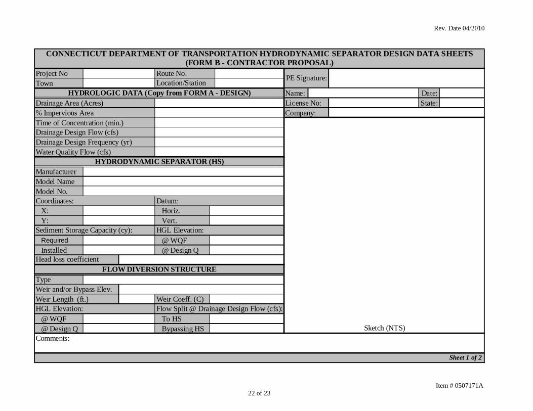
Upon conclusion of the HGL analysis, the Hydrodynamic Separator Design Data Sheets (Form B – Contractor Proposal) shall be completed by entering the HGL analysis data and other required information. Hydrodynamic Separator Selection: To ensure compliance with the special provision, the selection process of a proprietary hydrodynamic separator for installation on a Department project is outlined by the following steps:
1. First, select the available product(s) from Table 2 (PERFORMANCE MATRIX FOR CONNDOT APPROVED HYDRODYNAMIC SEPARATORS) that meet or exceed the WQF treatment specified on the Hydrodynamic Separator Design Data Sheets (Form A - Design) attached to this specification. The Engineer shall reject any proposed hydrodynamic separator system/model that is not listed in Table 2.
2. Using Table 3 (STANDARD SEDIMENT STORAGE CAPACITY FOR
CONNDOT APPROVED HYDRODYNAMIC SEPARATORS), check whether the initially selected product(s) in Step 1, meet or exceed the minimum sediment storage requirement specified on the Hydrodynamic Separator Design Data Sheets (Form A - Design). In some cases, the required sediment storage capacity will govern the model size required for the project. In lieu of selecting a larger model to accommodate the sediment storage requirement, the Contractor may submit working drawings as recommended by the Manufacturer, showing how a standard model has been modified to satisfy the sediment storage requirement. When a modification is proposed by increasing the depth of the standard structure, Table 4 (SEDIMENT STORAGE CAPACITY CALCULATION) shall be utilized to determine the sediment storage capacity of the proposed structure.
3. Hydrodynamic separator system/models pre-approval by the Department shall
not be construed to mean that all products appearing on Tables 2 and 3 are suitable to any specific project site or drainage design. The Contractor shall verify the constructability of the selected hydrodynamic separator in relation to dimensional, structural, geotechnical and right-of-way constraints at each installation site. If revisions to the drainage design, including the system layout, are required to accommodate the selected separator, the Contractor shall provide working drawings showing the revised layout, including the position of the hydrodynamic separator and the number, positions and types of connecting structures, the design of the flow diversion structure, and any other components of the system within the pay limits. The working drawings shall be prepared in sufficient detail to perform a hydraulic analysis and confirm that the layout will fit the constraints of each site.
4. Upon determination that the WQF, sediment storage and constructability
requirements have been met, the Contractor shall prepare or have prepared, a HGL analysis in accordance with the hydraulic requirements of this special provision, that includes the selected hydrodynamic separator and any revisions to the drainage design needed for the installation.
Item # 0507171A 15 of 23
Rev. Date 04/2010
5. The Hydrodynamic Separator Design Data Sheets (Form B – Contractor Proposal) shall be completed and signed by a professional engineer licensed by the State of Connecticut.
6. Acceptance of the computations by the Engineer must be obtained by the Contractor
prior to the purchase or installation of any units. Materials: Materials utilized to fabricate, construct and install the precast concrete hydrodynamic separator including but not limited to precast concrete units, brick, concrete masonry units, manhole frames and covers shall meet the requirements specified in the Standard Specifications, Form 816, Article M.08.02, except that the 28 day compressive strength specified in Subarticle M.08.02-4, shall be a minimum of 4000 psi (27.6 MPa). The Contractor shall provide a Materials Certificate in accordance with 1.06.07 for each unit delivered to the project. Upon request, the Contractor shall also provide Certified Test Reports for the fine and coarse aggregates and all cementitious materials, and the concrete mix design indicating the weight of each component, used in the construction of the precast units for review. The structures shall not be shipped until released by the Contractor’s Quality Control Manager or designee. The wall and slabs of the precast concrete units shall be designed to sustain HS20-44 (MS18) loading requirements. Manholes and Catch Basins shall conform to Section 5.07 of Form 816. Granular fill shall conform to the requirements of Article M.02.01 of Form 816. Non-shrink grout shall conform to the requirements of Subarticle M.03.01-12 of Form 816. Drainage pipe, sealant and gaskets shall conform to the requirements of Article M.08.01 of Form 816. Mortar shall conform to the requirements of Article M.11.04 of Form 816. Sealant used for the hydrodynamic separator unit(s) shall be resistant to oil and other hydrocarbons and conform to the requirements of ASTM C-443. Working Drawings: Working drawings in accordance with Article 1.05.02 – 2 shall be required for the system selected by the Contractor. The working drawings shall include the HGL analysis and all other computations in strict accordance with the “Hydraulic Design” section of this special provision, including a completed Form B – Contractor Proposal. If revisions to the layout of the system within the payment limits of this item are required to accommodate the selected separator, the working drawings shall also include plans that show the required revisions. These plans shall show the revised position of the hydrodynamic separator unit(s), and all revisions to connecting structures, pipes, elevations, and details, including the design within the flow diversion structure. The revised plans shall also include the pay limit showing all the components of the system that are included in this lump sum pay item.
Item # 0507171A 16 of 23

Rev. Date 04/2010
Working drawings shall also show details for construction, reinforcing joints, internal and external components, any cast-in-place appurtenances, locations and elevations of pipe openings, access manhole locations and elevations, and type / method of sealing pipe entrances. Working drawings for each hydrodynamic separator on the project shall have all appropriate vertical dimensions referenced with elevations that are consistent with the project plans. In addition to any other structural, material or installation requirements, the working drawings shall clearly indicate the following information:
1. The elevation and flow rate when internal flow bypass would occur within the device.
2. The location, dimensions and volume (capacity) of the sediment storage area within the device.
The working drawings shall be sealed by a professional engineer licensed in the state where the devices are manufactured and that said engineer shall certify the device meets the minimum requirements of the ConnDOT Standards. The working drawing submission by the Contractor shall consist of the following documents:
1. Working drawings for each hydrodynamic separator proposed for installation on the project.
2. Hydraulic design calculations including the head loss documentation and completed
Hydrodynamic Separator Design Data Sheets (Form B – Contractor Proposal) with professional engineer signature for each hydrodynamic separator.
3. Copies of the pertinent construction plan, profile, cross section and detail sheets that
have been annotated with any proposed drainage revisions that are required for the installation of the proposed hydrodynamic separator(s). If no changes are required, the submittal shall note same.
4. An Operations and Maintenance Manual for each hydrodynamic separator describing
operations, inspection, maintenance procedures and any applicable warranty information.
Acceptance of the working drawing submission by the Engineer must be obtained by the Contractor prior to the fabrication of each hydrodynamic separator and diversion structure. Construction Methods: The Contractor shall inspect the hydrodynamic separator and any accessory equipment upon delivery for general appearance, dimensions, soundness or damage in a manner acceptable to the Engineer. If any defects or damage are identified by the inspection, the unit shall be rejected by the Contractor and a new undamaged hydrodynamic separator shall be supplied. Any required adjustments of the separator shall be completed in accordance with Manufacturer’s recommendations. A Manufacturer’s representative and the Engineer will inspect the hydrodynamic separator before installation.
Item # 0507171A 17 of 23

Rev. Date 04/2010
The Contractor shall install the hydrodynamic separator structure in accordance with the Manufacturer’s recommendations unless otherwise directed by this specification or by the Engineer. The hydrodynamic separator shall be installed plumb, level and aligned both vertically and horizontally with the inlet and outlet piping. The hydrodynamic separator shall be placed on a compacted granular fill base in accordance with the Manufacturer’s specifications or a minimum thickness of 6” (150mm) whichever is larger. Anchoring systems shall be installed, where needed, to resist buoyancy forces. Care shall be taken not to damage the hydrodynamic separator during backfill and compaction. Pipe openings in the hydrodynamic separator shall be sized to accept pipes of the specified size(s) and material(s) as shown on the contract drawings and shall be sealed by the Contractor in accordance with the requirements of this specification. The inlet and outlet pipe connections shall be watertight. The hydrodynamic separator shall be tested for leakage according to the Manufacturer’s specifications and to the satisfaction of the Engineer. Any leaks must be found and corrected to the satisfaction of the Engineer prior to acceptance of the structure. Access openings with manhole frames and covers shall be provided to all chambers of the hydrodynamic separator. The access openings and pipe openings shall be detailed on the working drawings to be submitted by the Contractor for review and acceptance by the Engineer. All connecting structures and pipes included within the payment limits for this work shall be constructed in accordance with the applicable requirements of Article 5.07.03 and Article 6.51.03. Method of Measurement: Design, construction, furnishing, installation and cleaning of the hydrodynamic separator, the flow diversion structure, manholes and pipes as shown on the contract drawings, including all internal and external appurtenances and materials used, will be paid for on a lump sum basis per site. Basis of Payment: This work will be paid for at the contract lump sum for “HYDRODYNAMIC SEPARATOR”, complete in place, which price shall include all work within the pay limits shown on the contract drawings for hydrodynamic separator. If revisions to the layout of the system within the payment limits for this item are required to accommodate the selected separator, the lump sum price shall also include all additional or revised connecting structures and pipes. The contract lump sum shall include, but not be limited to, the following:
1. Design, preparation, revisions of working drawings and hydraulic computations.
2. Concrete and reinforcing steel, sealant, cement, mortar, flexible rubber sleeves, internal and external components, brick and masonry, frames and covers used to construct access manholes.
3. Flow diversion structure, manholes and pipes as shown on the contract drawings, or
as revised and shown on submitted working drawings accepted by the Engineer.
4. Structure excavation, back fill, and disposal of surplus material.
5. Compacted granular fill.
Item # 0507171A 18 of 23

Rev. Date 04/2010
Item # 0507171A 19 of 23
6. Trench excavation and bedding material.
7. Cleaning of the Hydrodynamic Separator, flow diversion structure, manholes and pipes as shown on the contract drawings (of all debris every 90 days, or as needed), during the duration of the project, shall also be included in the price of this item.
8. The Operations and Maintenance Manual for each hydrodynamic separator.
The price shall include but not be limited to all materials, testing, equipment, tools and labor incidental thereto. Attachments: The following documents are attached to this specification:
1. Hydrodynamic Separator Design Data Sheets (Form A – Design), Sheets 1 & 2 of 2.
2. Hydrodynamic Separator Design Data Sheets (Form B – Contractor Proposal), Sheets 1 & 2 of 2 (blank), to be completed and submitted with the working drawings.

Rev. Date 04/2010
SAMPLE DATA
HD Date: 4/1/2010DM Date: 4/1/2010
X: Horiz.Y: Vert.
Maximum Flow to HS at Drainage Design Flow (cfs)Comments:
4
Sheet 1 of 2
@ Design QTo HSBypassing HS 7.6
3.2@ WQFFlow Split @ Drainage Design Flow HGL Elevation:
HGL Elevation:104.13
Weir Coeff. (C)Weir and/or Bypass Elev.Weir Length (ft.)
Required 104.85@ Design Q
Drainage Design Flow (cfs)
Type
State Plane NAD83NGVD-1929
Drainage Design Frequency (yr)Water Quality Flow (cfs)
XXX,XXX
1.7HYDRODYNAMIC SEPARATOR (HS)
YYY,YYY
ConnDOT
Sketch (NTS) - Indicate Pay limits
Coordinates: Datum:
Head loss coefficient 1.75
3.3
FLOW DIVERSION STRUCTURE
Sediment Storage Capacity (cy):
Town
5311
Prepared By:Checked By:
Company:Drainage Area (Acres)Percent Impervious Area %Time of Concentration (min.)
Project No
@ WQF
CONNECTICUT DEPARTMENT OF TRANSPORTATION HYDRODYNAMIC SEPARATOR DESIGN DATA SHEETS(FORM A - DESIGN)
HYDROLOGIC DATA
ExampleSomewhere
Route No.Location/Station
0Site 1
Comments:
3.7
10
4' Diameter Manhole104.50
105.20
1.0
4.3
104.20
10.8I-3
I-4
J-1
J-2HS
OUT
P-3P-4
P-5
P-6
P-7
P-8
APPROX. PAY LIMITS
Item # 0507171A 20 of 23

Rev. Date 04/2010
SAMPLE DATA
Date:
Pipe
Dow
nstream
Str.
Pipe Size (in)
Flow (cfs)
Ground Elev. O
UT (ft)
Invert Elev. OU
T (ft)
HGL O
UT (ft)
Depth O
UT (ft)
Vel. Head
OUT (ft)
EGL OU
T (ft)
Length (ft)
Friction Slope (ft/ft)
Friction Loss (ft)
EGL IN
(ft)
Vel. H
ead IN
(ft)
HGL IN
(ft)
Depth IN (ft)
Invert Elev. IN (ft)
Ground Elev.
IN (ft)
Upstream
Str.
Headloss Coeff.
Str. headloss (ft.)
WQFP-6 OUT 24 1.70 106.48 103.04 103.47 0.43 0.19 103.65 25 0.0047 0.12 103.77 0.16 103.61 0.45 103.16 108.86 J-2 0.01 0.00P-8 J-2 12 1.70 108.86 103.16 103.71 0.55 0.23 103.94 6 0.0058 0.03 103.97 0.21 103.76 0.57 103.19 108.86 HS 1.75 0.37P-7 HS 12 1.70 108.86 103.19 104.13 0.94 0.08 104.21 6 0.0017 0.01 104.22 0.08 104.14 0.91 103.23 109.19 J-1 0.82 0.06P-4 J-1 24 1.70 109.19 103.23 104.20 0.97
10 YR DESIGN FLOWP-6 OUT 24 10.80 106.48 103.04 104.20 1.16 0.51 104.71 25 0.0048 0.12 104.83 0.49 104.34 1.18 103.16 108.86 J-2 0.05 0.02P-8 J-2 12 3.20 108.86 103.16 104.36 1.20 0.26 104.62 6 0.0069 0.04 104.66 0.26 104.40 1.21 103.19 108.86 HS 1.75 0.45P-7 HS 12 3.20 108.86 103.19 104.85 1.66 0.26 105.11 6 0.0069 0.04 105.15 0.26 104.89 1.66 103.23 109.19 J-1 1.18 0.31P-4 J-1 24 10.80 109.19 103.23 105.20 1.97 0.18 105.38 88 0.0018 0.16 105.54 0.24 105.30 1.63 103.67 112.96 I-4 0.11 0.03P-3 I-4 24 9.10 112.96 103.87 105.33 1.46 0.22 105.55 185 0.0041 0.76 106.31 0.43 105.88 1.08 104.80 109.55 I-3
P-6 OUT 24 10.80 106.48 103.04 104.2 1.16 0.51 104.71 25 0.0048 0.12 104.83 0.49 104.34 1.18 103.16 108.86 J-2 0.05 0.02P-5 J-2 24 7.60 108.86 103.16 104.36 1.20 104.36 1.13 103.23 109.19 J-1
Sheet 2 of 2
CONNECTICUT DEPARTMENT OF TRANSPORTATION HYDRODYNAMIC SEPARATOR DESIGN DATA SHEETS(FORM A - DESIGN)
4/1/2010Project No: Example Location/Station: Site 1HYDRAULIC GRADE LINE ANALYSIS
Item # 0507171A 21 of 23
Rev. Date 04/2010
Item # 0507171A 22 of 23
Project NoTown
Name: Date:Drainage Area (Acres) License No: State:% Impervious Area Company:Time of Concentration (min.)Drainage Design Flow (cfs)Drainage Design Frequency (yr)Water Quality Flow (cfs)
ManufacturerModel NameModel No.
X: Horiz.Y: Vert.
Required @ WQFInstalled @ Design Q
TypeWeir and/or Bypass Elev.Weir Length (ft.) Weir Coeff. (C)
@ WQF To HS@ Design Q Bypassing HS
Sheet 1 of 2
Comments:
Head loss coefficient
Flow Split @ Drainage Design Flow (cfs):
Datum:
Sketch (NTS)
HYDRODYNAMIC SEPARATOR (HS)
FLOW DIVERSION STRUCTURE
Sediment Storage Capacity (cy):
HGL Elevation:
Coordinates:
CONNECTICUT DEPARTMENT OF TRANSPORTATION HYDRODYNAMIC SEPARATOR DESIGN DATA SHEETS(FORM B - CONTRACTOR PROPOSAL)
HYDROLOGIC DATA (Copy from FORM A - DESIGN)
PE Signature:Route No.Location/Station
HGL Elevation:
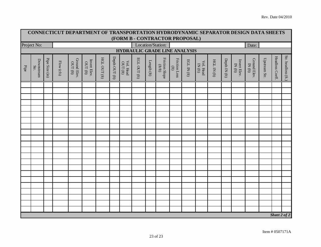
Rev. Date 04/2010
Date:
Pipe
Dow
nstream
Str.
Pipe Size (in)
Flow (cfs)
Ground Elev. O
UT (ft)
Invert Elev. O
UT (ft)
HGL O
UT (ft)
Depth O
UT (ft)
Vel. Head
OU
T (ft)
EGL OU
T (ft)
Length (ft)
Friction Slope (ft/ft)
Friction Loss (ft)
EGL IN
(ft)
Vel. Head IN (ft)
HGL IN (ft)
Depth IN (ft)
Invert Elev. IN
(ft)
Ground Elev.
IN (ft)
Upstream
Str.
Headloss Coeff.
Str. headloss (ft.)
Sheet 2 of 2
CONNECTICUT DEPARTMENT OF TRANSPORTATION HYDRODYNAMIC SEPARATOR DESIGN DATA SHEETS(FORM B - CONTRACTOR PROPOSAL)
HYDRAULIC GRADE LINE ANALYSISProject No: Location/Station:
Item # 0507171A 23 of 23