itec420 software engineering lecture 5: recap & hw ...box/itec420/lecture05.pdf ·...
TRANSCRIPT

1/9/14
Towards creating survivable architecture 1
ITEC420: Software Engineering Lecture 5: Recap & HW Implementation & Testing Workflows Box Leangsuksun SWECO Endowed Professor, Computer Science Louisiana Tech University [email protected]
CTO, PB Tech International Inc. [email protected]
Some Important Annoucement
• Cancel mid term on Jan 9 but will be a quiz due to midterm and final are 1.5 weeks away.
• There will be an industry talk on Jan 9 at 5:30
1/9/14 2
1/9/14
Towards creating survivable architecture 2
Software Engineering talk
• Title: Lean or Agile software engineering process: an industry perspective
• By Keith Hanson, CEO, Twin Engine Labs • Time & Place: 5:30pm, Jan 9 2014, Bogard Hall
1/9/14 3
Product Life cycle (RUP)
Class Diagram

1/9/14
Towards creating survivable architecture 3
View of Software Engineering
User Needs/Inputs – Specification or Requirement
Technical: Design/Analysis Implementation
Project/Product Management:
Manufacturing/ Quality Control
Marketing
Sale
Typical SE life cycle process
• User Inputs -> Requirements and Specification • Design & Analysis -> Analysis & Design documents • Implementation -> Programming, integration, Tools ->
Code or system • Testing -> Test Plan & Test results • Manufacturing, installation/Deployment and Quality
Control -> Change Management & Configuration Management.
• A classic water model.. Not good..why? • the above SE workflow can be divided into smaller
iterations
1/9/14
Towards creating survivable architecture 4
Recap: requirements, analysis & design
Requirements and Specifications
• User Inputs/expectations are translated into agreement documents among users/customers and various stakeholders in SE lifecycle
• Can be legal documents between client and supplier
• How do we know whether the software product will meet the expectation?

1/9/14
Towards creating survivable architecture 5
Requirements and Specifications
• Functional Requirements – Tangible Needs – E.g. your order processing system, online store with shopping cart.
• Non-Functional Requirements – Performance (how well your system can perform, # transaction) – Reliability (how long your system can run w/o failure or what is
uptime?)
• How do we know whether the software product will meet the expectation?
What are requirements? • “What customers or users expect from the
system” • Two types
– Functional Requirements • Features (more tangible)
– Non-functional requirements • Reliability and performance (equally if not more)
1/9/14
Towards creating survivable architecture 6
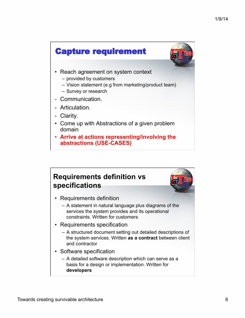
Capture requirement
• Reach agreement on system context – provided by customers – Vision statement (e.g from marketing/product team) – Survey or research
- Communication. - Articulation. - Clarity. • Come up with Abstractions of a given problem
domain • Arrive at actions representing/involving the
abstractions (USE-CASES)
Requirements definition vs specifications • Requirements definition
– A statement in natural language plus diagrams of the services the system provides and its operational constraints. Written for customers
• Requirements specification – A structured document setting out detailed descriptions of
the system services. Written as a contract between client and contractor
• Software specification – A detailed software description which can serve as a
basis for a design or implementation. Written for developers

1/9/14
Towards creating survivable architecture 7
Requirements readers
Client managersSystem end-usersClient engineersContractor managersSystem architects
System end-usersClient engineersSystem architectsSoftware developers
Client engineers (perhaps)System architectsSoftware developers
Requirementsdefinition
Requirementsspecification
Softwarespecification
Use case process & notation
• Identify actors • Brain-storm actions that will lead to features/
promises to customers • Refine use-cases and add exception cases • eg. A doctor clinic
1/9/14
Towards creating survivable architecture 8
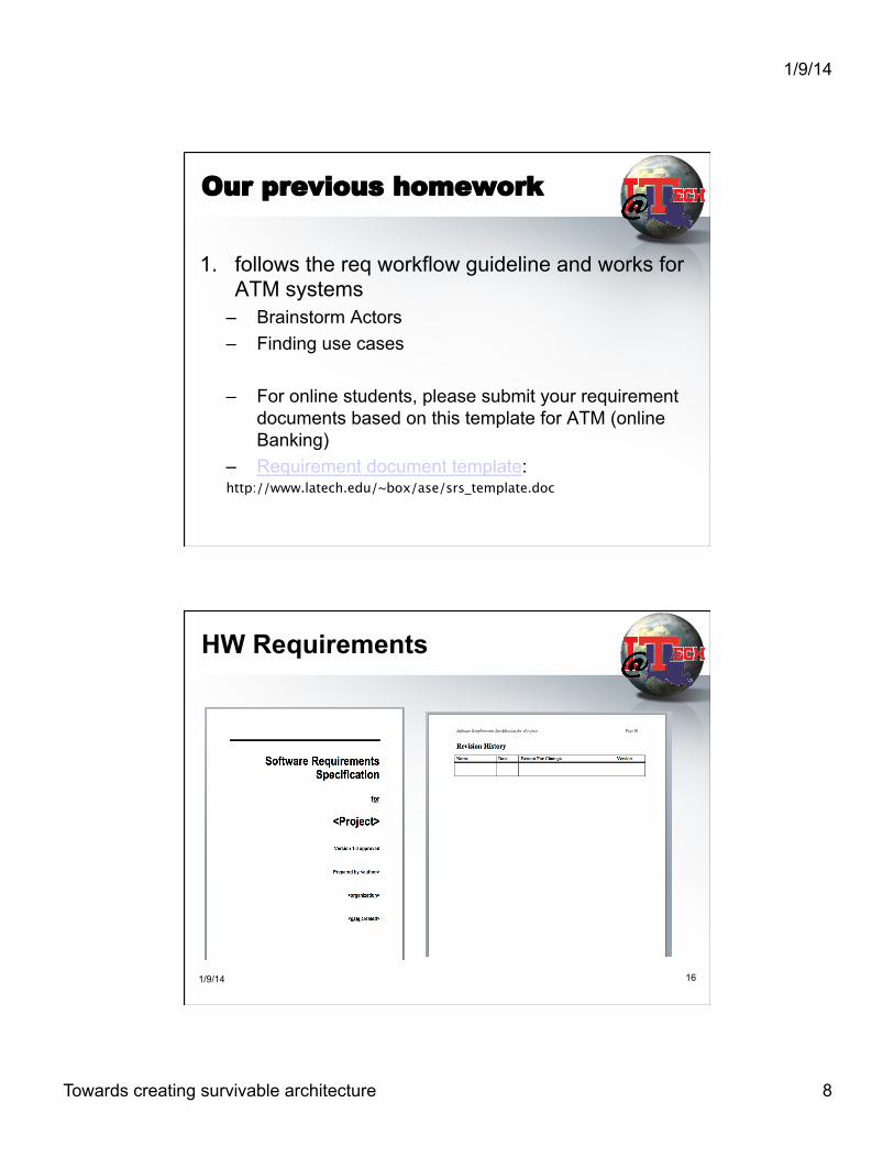
Our previous homework
1. follows the req workflow guideline and works for ATM systems
– Brainstorm Actors – Finding use cases
– For online students, please submit your requirement documents based on this template for ATM (online Banking)
– Requirement document template: http://www.latech.edu/~box/ase/srs_template.doc
HW Requirements
1/9/14 16

1/9/14
Towards creating survivable architecture 9
Use Cases for ATM homework
Login/Swipe Card
Enter Pin
Check Account
ATM
Use Cases (continued)
withdraw
deposit
transfer
ATM
1/9/14
Towards creating survivable architecture 10
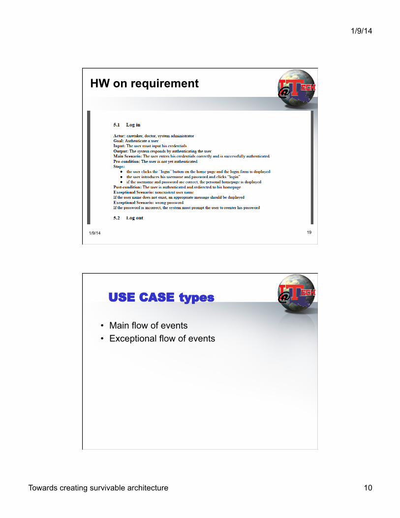
HW on requirement
1/9/14 19
USE CASE types
• Main flow of events • Exceptional flow of events

1/9/14
Towards creating survivable architecture 11
Recap: The Analysis Workflow
Purpose of Analysis & Design
• To transform the requirements into a design of the system to-be.
• To evolve a robust architecture for the system.
• An Architecture document & later design documents (for each subsystem, modules)
• To adapt the design to match the implementation environment, designing it for performance.

1/9/14
Towards creating survivable architecture 12
What is system architecture?
• A blueprint for software system • Includes
– High Level Software components/subsystem – High Level Hardware components/subsystem – Relationship/connectivity – Data Models (optional)
1/9/14 23
Define Candidate Architecture
• Create an initial sketch of the architecture of the system
• Identify analysis classes from the architecturally significant use cases
• Update the use-case realizations with analysis class interactions

1/9/14
Towards creating survivable architecture 13
Analysis Artifacts (UML)
Robustness Diagram: Usually contains attributes, not operations. • Boundary Classes • Control Classes • Entity Classes
Symbol:
Symbol:
Symbol:
Example of Robustness Diagram: Login usecase
Authenticated
Validation
User: John Doe
Pin: 1234
Account number: 111111111
Account value: $25,678.56
Address: PO box 7543 Ruston, La 71270
Validation Account ATM Keypad
Actor

1/9/14
Towards creating survivable architecture 14
Sequence DIAGRAM (in design worflow)
Home page Login page Account
login()
display()
enter user and password()
validate user login()
display()
Actor1
Recap: Design Workflow
1/9/14
Towards creating survivable architecture 15
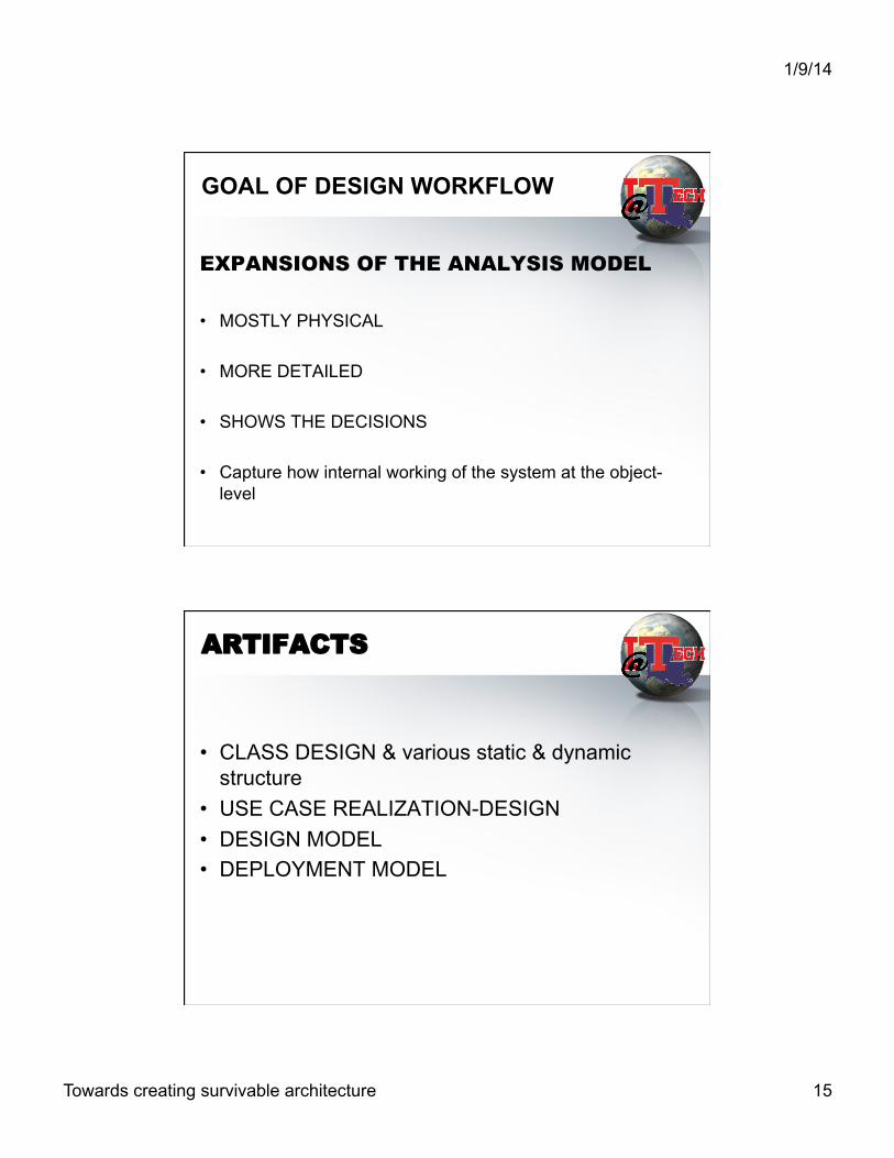
GOAL OF DESIGN WORKFLOW
EXPANSIONS OF THE ANALYSIS MODEL • MOSTLY PHYSICAL • MORE DETAILED • SHOWS THE DECISIONS
• Capture how internal working of the system at the object-level
ARTIFACTS
• CLASS DESIGN & various static & dynamic structure
• USE CASE REALIZATION-DESIGN • DESIGN MODEL • DEPLOYMENT MODEL
1/9/14
Towards creating survivable architecture 16
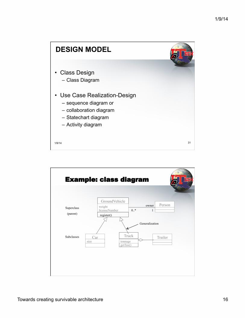
DESIGN MODEL
• Class Design – Class Diagram
• Use Case Realization-Design – sequence diagram or – collaboration diagram – Statechart diagram – Activity diagram
1/9/14 31
Example: class diagram
GroundVehicle weight licenseNumber register()
Person
Car size
getTax()
Truck tonnage
Trailer
0..* 1 owner
Generalization
Superclass
(parent)
Subclasses

1/9/14
Towards creating survivable architecture 17
Activity Diagram (flow chart)
STATECHART DIAGRAM
Example for a statechart diagram of an order class

1/9/14
Towards creating survivable architecture 18
Sequence DIAGRAM
Home page Login page Account
login()
display()
enter user and password()
validate user login()
display()
Actor1
COLLABORATION DIAGRAM

1/9/14
Towards creating survivable architecture 19
architectural design
• Come up with a system layout – Subsystems -> component/interface
• Top down vs bottom up
Deployment Diagram
1/9/14
Towards creating survivable architecture 20
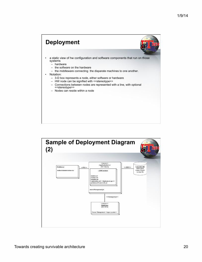
Deployment
• a static view of hw configuration and software components that run on those systems – hardware – the software on the hardware – the middleware connecting the disparate machines to one another.
• Notation: – 3-D box represents a node, either software or hardware – HW node can be signified with <<stereotype>> – Connections between nodes are represented with a line, with optional
<<stereotype>> – Nodes can reside within a node
Sample of Deployment Diagram (2)
This diagram is excerpted from intro to UML 2 deployment diagram, http://www.agilemodeling.com/artifacts/deploymentDiagram.htm

1/9/14
Towards creating survivable architecture 21
Summary on the recap
• User input -> requirements (usecases in UML) • Use case oriented analysis, design & development
as well as testing • To ensure that customers’ expectations are
met based on use case and quality assurance process
1/9/14 41
l What are main activities in these workflows?
l Requirement l Analysis l Design
1/9/14
Towards creating survivable architecture 22
Implementation Work Flow
Introduction • Fundamental goal is to build a working version of
system. • Craft out the Architecture • Implement the Design in terms of components. • Plan System Integrations • Implement Design classes and subsystems • Unit test components • Integrate Components.

1/9/14
Towards creating survivable architecture 23
Implementation Workflow Activities and Workers
Architect!& Developers!
System Integrator!
Component!Engineer!
Architectural!Implementation!
Integrate!System!
Implement!a Class!
Implement a!Subsystem/component!
Perform a Test!
Artifacts
• Implementation Model - Component - Implementation subsystem - Interface • Architecture Description - View of Implementation Model
• Integration Build Plan
1/9/14
Towards creating survivable architecture 24
Implementation
• Describes how elements of design model are implemented in terms of components such as source code, executable, etc.
• Write programs, write or acquire framework or components (IDE, J2EE or AMPP MVC etc)
• Describe how components are organized using the structuring and modularization mechanisms of the implementation environment and programming languages
• Hierarchy of Implementation (sub) Systems containing Components and Interfaces
Component
• Physical packaging of model elements • Standard stereotypes which the UML assigns
– <<executable>> -- a program that may run on a node – <<library>> -- static or dynamic library – <<file>> -- static or dynamic library – <<table>> -- a database table – <<document>> -- a document – technology specific (<<ActiveX>>, <<Applet>>,
<<DLL>>, <<CORBA Component>>, etc.)

1/9/14
Towards creating survivable architecture 25
Component Diagram
<<Page>> Search.html
<<page>> Front.html
<<table>> Book.html
<<Executable>> Search.exe
<<table>> Author.
Implementation of subsystem or components • Organize implementation model artifacts into
more manageable pieces • Manifested by a “packaging mechanism” in
implementation environment – Component packages – Interfaces
• Trace one-to-one with design subsystems – same dependencies to other subsystems, interfaces – provides same interfaces
• maps one-to-one with which components or other implementation subsystems within the subsystem provide the interfaces of the subsystem
1/9/14
Towards creating survivable architecture 26
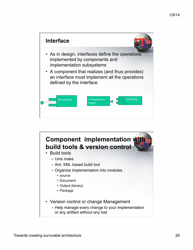
Interface
• As in design, interfaces define the operations implemented by components and implementation subsystems
• A component that realizes (and thus provides) an interface must implement all the operations defined by the interface
Accounting
<<interface>> Post()
Accounting
Component implementation with build tools & version control • Build tools
– Unix make – Ant: XML based build tool – Organize implementation into modules
• source • Document • Output (binary) • Package
• Version control or change Management – Help manage every change to your implementation
or any artifact without any lost

1/9/14
Towards creating survivable architecture 27
Architectural Description
• implementation model • Decomposition of implementation model into
subsystems, their interfaces, and dependencies between them
• Key components – trace to architecturally significant design classes – executable components – components that are general, central, or implement
generic design mechanisms that many other components depend on
Integration Build Plan
• Describes the build (SW product) that will occur with In a given iteration.
• Build plan for each increment – list of functionality: use cases and/or scenarios – list of implementation subsystems and components
• Test each build, including regression tests • Configuration management with the build plan

1/9/14
Towards creating survivable architecture 28
WORKERS v ARCHITECT v COMPONENT ENGINEER or Developer v SYSTEM INTEGRATOR
ARCHITECT
• Outlines the implementation model. • Ensure the completeness and correctness. • Mapping the executable components onto
nodes within the deployment model. • Include the components from the implementation model and the updated contents
of deployment model.

1/9/14
Towards creating survivable architecture 29
Component Engineer/Developer
• Is responsible for the source code of the components and subsystems.
• For coding the interfaces associated with components and subsystems.
• Is responsible for unit testing of his or her components.
Unit Testing
• Performed by a developer
• Specification testing
• Note that black box testing is not unit testing • Structural testing or white box testing
» control flow graph » Method flow graph » Class flow graph

1/9/14
Towards creating survivable architecture 30
System Integrator
• Is responsible for designing integration build plan and performing incremental integration & perhaps regression test .
Implementation Workflow Activities and Workers
Architect!
System Integrator!
Component!Engineer!
Architectural!Implementation!
Integrate!System!
Implement!a Class!
Implement a!Subsystem!
Perform a Unit Test!
1/9/14
Towards creating survivable architecture 31
CSC 532: Advanced Software Engineering
The Test Workflow
Main Goals
• To ensure that the system offers a high degree of quality before it’s delivered to customers
• Result: Test Model • Use-case oriented testing • Quality Gate
– Entrance Criteria – Exit Criteria

1/9/14
Towards creating survivable architecture 32
Artifacts
• Test Case Ø Black-box testing-use cases Ø White-box testing-use case
realizations-design Ø Integration testing-system level • Test Procedure How to perform
Sample of test cases
1/9/14 64
1/9/14
Towards creating survivable architecture 33
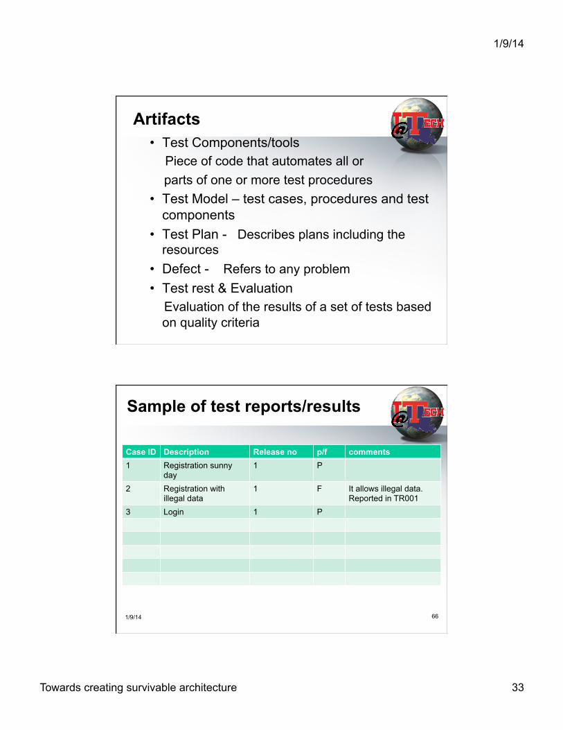
• Test Components/tools Piece of code that automates all or parts of one or more test procedures • Test Model – test cases, procedures and test
components • Test Plan - Describes plans including the
resources • Defect - Refers to any problem • Test rest & Evaluation Evaluation of the results of a set of tests based
on quality criteria
Artifacts
Sample of test reports/results
Case ID Description Release no p/f comments 1 Registration sunny
day 1 P
2 Registration with illegal data
1 F It allows illegal data. Reported in TR001
3 Login 1 P
1/9/14 66

1/9/14
Towards creating survivable architecture 34
Sample of Entrance Criteria for system test
• All code must be passed unit test at 98% • Code must be ensured no memory leak • IT test must be passed • All code must be ITpassed in the change control
1/9/14 67
Sample of Exit Criteria for system test
• There must be 95% SVpass for a total test cases in the current release.
• No severity 1 opened change requests • All code must be ITpassed in the change control • Mean Time To Failure must be greater than 2
days (non-functional requirements)
1/9/14 68

1/9/14
Towards creating survivable architecture 35
Workers
• Test Engineer/SVV -Planning Integration, system and regression testing -Selecting and describing test cases and corresponding test procedures -Ensuring the completeness and correctness -Evaluating the results of testing
• Component Engineer -Building one or more test components
• Integration Tester – Integration testing on each build of the system
• System Tester – System testing on each build of the system
1/9/14
Towards creating survivable architecture 36
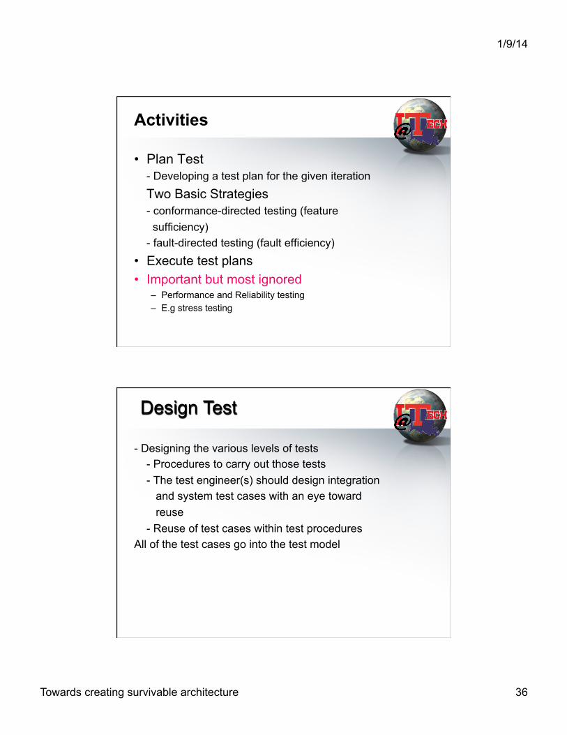
Activities
• Plan Test - Developing a test plan for the given iteration
Two Basic Strategies - conformance-directed testing (feature sufficiency) - fault-directed testing (fault efficiency)
• Execute test plans • Important but most ignored
– Performance and Reliability testing – E.g stress testing
- Designing the various levels of tests - Procedures to carry out those tests - The test engineer(s) should design integration and system test cases with an eye toward reuse - Reuse of test cases within test procedures All of the test cases go into the test model
Design Test
1/9/14
Towards creating survivable architecture 37
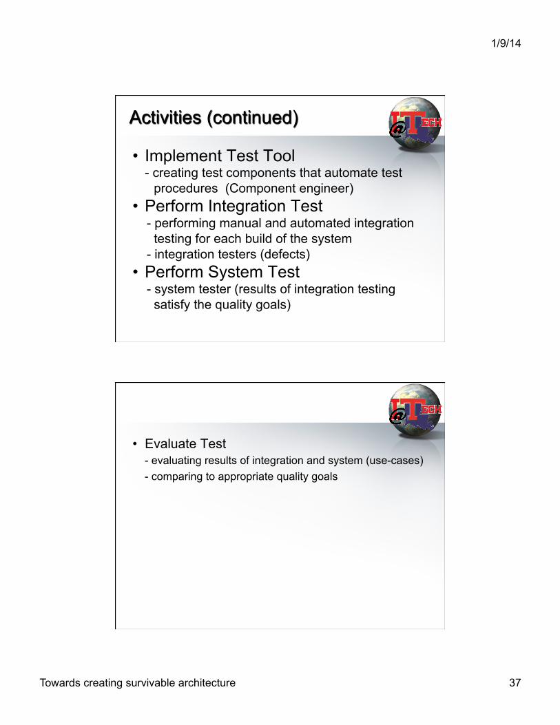
• Implement Test Tool - creating test components that automate test
procedures (Component engineer) • Perform Integration Test - performing manual and automated integration testing for each build of the system - integration testers (defects) • Perform System Test - system tester (results of integration testing satisfy the quality goals)
Activities (continued)
• Evaluate Test - evaluating results of integration and system (use-cases) - comparing to appropriate quality goals

1/9/14
Towards creating survivable architecture 38
Key Measure
• Completeness of testing or Coverage • Reliability • Performance
Test Workflow Activities
Plan Test Design Test Implement Test
Evaluate Test
Perform Integration Test
Perform System Test

1/9/14
Towards creating survivable architecture 39
How to make decision: Readiness of your project
• Requirement & Test Plan • Objective and Criteria
– Entrance Criteria – Exit Criteria
• Quality Model and Measurement (Software Metrics)
Failure/Defect Severity Classification—System
• Example by Capability Impact excerpted from Musa 1998 book
Class System capability impact
1 Basic service interruption
2 Basic service degradation
3 Inconvenience, correction not deferrable
4 Minor tolerable effects, correction deferrable

1/9/14
Towards creating survivable architecture 40
Example of Acceptance Chart by FIO
RUP First half summary
• Source: P. Kruchte, What is the RUP? http://www.therationaledge.com/content/jan_01/f_rup_pk.html

1/9/14
Towards creating survivable architecture 41
End chapter Questions/Review
l What are main activities in this workflow?
l Describe what are necessary tools or processes in this workflow and how they can help growing maturity of, improving quality of the SW product?