iteams – units 1-5do the same with the other pieces of tape at the 65 cm line, the 50 cm line, and...
TRANSCRIPT

ITEAMS - President and Fellows of Harvard College
1
ITEAMS – Exploration – Your Eye and a Telescope I. (Adapted from From the Ground Up)
(Name) _________ Learning Goal: To compare your eyes to a telescope. Career Focus: X-Ray and MRA Technologists and Diagnosticians, Photography, Video and Movie Direction and Production.
Recording Your Ideas 1. In what ways is the telescope shown below like the eyes of the person whose face is also shown? List below all the ways you think they might be the same.
______________________________________________________________________________ ______________________________________________________________________________
2. In what ways is a telescope different than your eyes? List your reasons below. ____________________________________________________________________________
____________________________________________________________________________ Exploration Procedure Collect the following materials. ✔ Materials Checklist/Part 1 Small metric ruler ✔ Materials Checklist/Part 2 Meter stick Masking tape

ITEAMS - President and Fellows of Harvard College
2
Part 1. “With Eyes Wide Open”
1. Work with a partner. Look at the pupil of your partner’s eye (the black part of the eye). Compare the size of the pupil with the dark circles below and select the circle that best matches the pupil size. (CAUTION: Do not put a ruler or any other object close to anyone’s eyes!) Measure the width (diameter) of the circle (in mm) and record it in the Table 1. In the same way have your partner estimate the size of your pupil and record it in Table 1.
● ● ● ● ● ● ● ● ● 2. Observe that the size of one’s pupil changes depending on whether you are in dim or
bright light. With your partner locate a place where the light is dim, like a hallway. Let your eyes adapt and measure the width of your pupils as you did in Step 1. Record the pupil sizes in Table 1. Find a location where the light is very bright. Again, let your eyes adapt and measure the width of your pupils as you did in Step 1. Record the pupil sizes in Table 1.
Table 1 – Estimated Size of Pupil Pupil Size in Regular
Light (mm) Pupil Size in Dim Light (mm)
Pupil Size in Bright Light (mm)
My Partner’s Pupil
My Own Pupil
3. Does a MicroObservatory robotic telescope let in more light than your eye? The opening
(called an aperture) on the telescope is about 150 mm (15 cm or about 6 inches) in diameter. How much wider is the telescope’s aperture than your pupil at its largest? (Show math below.) Which do you think lets in more light, your eye or the telescope?
________________________________________________________________________
________________________________________________________________________
4. (Optional) How much more light enters the telescope than enters your pupil at its largest?
You can determine the area of each; the formula to find the area of a circle is: A = πr2. But there is a shorter way to find an answer. If you know the diameter (d) or the radius (r) for both openings, all you need to do is determine the value of either d2 or r2 for each, and compare these values. (Show math below.)
________________________________________________________________________
________________________________________________________________________

ITEAMS - President and Fellows of Harvard College
3
Part 2. “In the Blink of Your Eye!” 1. Cameras and telescopes have shutters – solid shields that block light – that are used to
control the amount of light entering. We can control the shutter speed of both cameras and telescopes (the MicroObservatory shutter can be opened between 0.05 and 60 seconds). This is the exposure time. Your eye doesn’t have a shutter, but it does have a kind of “shutter speed.” It is the time it takes for the eye’s nerve cells to record an image before sending it unto your brain. This is like the eye’s exposure time.
2. Here is a way to estimate your eye’s exposure time. Cut off four small pieces of masking
tape (about 5 cm, or 2 inches long). Put one piece of tape over the 70 cm line on a meter stick. Do the same with the other pieces of tape at the 65 cm line, the 50 cm line, and the 26 cm line. Rest the meter stick on a table with the masking tape facing up so you can write on the tape. On the piece of tape at the 70 cm line write zero seconds, or 0 s. On the tape at 65 cm write 0.1 s (that’s 1/10th of a second). At the 50 cm line write 0.2 s, and at the 26 cm line write 0.3 s.
3. To test your reaction time, have your partner hold the meter stick upright with the zero
second mark lowest. Hold your thumb and forefinger with the meter stick between them – but not touching the meter stick – so they are in line with the zero second mark. When your partner drops the meter stick, catch it as quickly as possible. After catching the meter stick use the time scale to see how quickly you caught it. Do three trials, record the data in Table 2, and calculate the average time to catch the meter stick. Have your partner do the same.
Table 2 – Estimated Time to Catch the Pencil or Ruler Trial 1 (sec) Trial 2 (sec) Trial 3 (sec) Average
Time (sec) My Time to Catch the Meter Stick
My Partner’s Time to Catch the Meter Stick
4. (Optional) In this part of the exploration you have been investigating your reaction time,
which includes the time it took for the nerves in your eyes to gather and react to the light (scattered from the meter stick), send a signal to your brain, and get ready to react again for a new image. That takes approximately 1/15th of a second, and then it starts all over again. This is like your eye’s exposure time. Compare this to the MicroObservatory telescope that can gather light for 60 seconds to make a single image. Determine how much longer the telescope’s exposure time is to that of your eyes. To do so, divide the maximum telescope exposure time by the eye’s exposure time. (Show math below.)
________________________________________________________________________
________________________________________________________________________

ITEAMS - President and Fellows of Harvard College
4
Interpreting the Results 1. In Part 1 you saw that the telescope opening was much larger than the size of your pupil, and if you did Optional Step 4 you saw the area of the telescope was many times larger. Describe how this enables us to see fainter objects in space. ____________________________________________________________________________ ____________________________________________________________________________ ____________________________________________________________________________ 2 In Part 2 you saw that the telescope exposure time was much greater than the exposure time of your eye. Describe how this enables us to see fainter objects in space. ____________________________________________________________________________ ____________________________________________________________________________ ____________________________________________________________________________ What I know about aperture and exposure time…

ITEAMS - President and Fellows of Harvard College
5
ITEAMS – Exploration – Your Eye and a Telescope II. (Adapted from From the Ground Up)
(Name) _________ Learning Goal: To compare your eyes to a telescope. Career Focus: Radiology Technologists, Forensic Science, Facial Recognition Fields, Medical Imaging and Analysis, Software Engineer. Recording Your Ideas 1. How far away do you think you can see a penny held by your partner? How far would you have to be for a penny to appear to be the same size as the Full Moon in the sky?
______________________________________________________________________________ ______________________________________________________________________________
2. Which do you think you could see more sharply – a penny across the room or the Moon through the MicroObservatory telescope? Explain. ____________________________________________________________________________
____________________________________________________________________________ Exploration Procedure Collect the following materials. ✔ Materials Checklist/Part 1 Small metric ruler Flashlight 7.5 cm (3.0 inch) square of Aluminum Foil

ITEAMS - President and Fellows of Harvard College
6
Drawing compass, pen, or pencil Masking or transparent tape Tape measure (optional) ✔ Materials Checklist/Part 2 Protractor Part 1. “How Sharp is Your Eye?”
5. Work with a partner. Using a drawing compass or point of a pencil or pen carefully punch out two small holes near the center of the aluminum foil about 3.0 millimeters (1/8 inch) apart. Each hole should be no more than 1.5 millimeters (1/16 inch) in diameter. Center the foil over the front of the flashlight and tape the edges to the flashlight. Turn on the flashlight to be certain you are able to see the light coming through both small holes.
6. Have your partner take the flashlight and move to the other end of a long corridor and
point the lighted flashlight toward you. Slowly walk toward your partner until you can just make out that there are two points of light side by side, rather than one point of light. Mark this location with some masking tape on the floor. Estimate the distance from that location to the flashlight using the length of your foot as about one foot. Alternatively, if you have a tape measure you can measure the distance more accurately. Record the distance in Table 1 below.
7. Repeat Step 2, and then switch roles so your partner can make the same estimates.
Calculate the average distance. Table 1 – Distance From Flashlight when Two Points of Light are Visible Trial 1 Distance (feet) Trial 2 Distance (feet) Average Distance (feet) Partner’s Estimate
Own Estimate
8. This is the distance at which you can see there are two objects or points of light; another
way to say this is that you can “resolve” the two points of light. Compare your results to those of your partner. If the distances are not close, whoever can resolve the two points of light at the greater distance may have “sharper” eyes!
Part 2. “How Wide is Your Vision?”
1. Work with a partner with each seated on opposite sides of a table. Place a protractor on the table in front of you with the straight edge of the protractor aligned along the edge of the table. Move as close to the table as possible.
2. Look straight ahead. Fully stretch out your left arm and while keeping it level to the table,
move your arm so that your hand is out of your field of view behind your head. Now

ITEAMS - President and Fellows of Harvard College
7
slowly bring your arm forward and at the same time wiggle your thumb. When you can just see your thumb, stop moving your arm and have your partner estimate the angle between your outstretched arm and a line directly straight ahead. Record the angle in Table 2 below. Do the same with your right arm and record the angle. Add the two angles together which will give you your field of view.
3. Switch roles with your partner and make the same estimations and calculations.
Table 2 – Field of View Angle to Left Hand
(degrees) Angle to Right Hand (degrees)
Sum of Two Angles, or Field of View (degrees)
My Partner’s Field of View
My Own Field of View
Interpreting the Results 1. Look back at the average distance you were able to distinguish or resolve the two points of light that were about 3 mm (1/8 inch) apart. Most people are able to resolve these two points of light at a distance of about 11 m (35 feet). MicroObservatory telescopes can resolve these same two points of light at a distance of about 267 m (875 feet). About how many times sharper is the telescope’s “vision” than your own (this can be called the resolving power of the telescope)? (Hint: Divide the resolving distance of the telescope by the resolving distance of your own eyes.) What is the advantage of using a telescope when looking at a distant object? ____________________________________________________________________________ ____________________________________________________________________________ ____________________________________________________________________________ 2. If you were on the beach pictured on the next page your eye could take in the whole scene (more the 90º wide). The main camera on a MicroObservatory telescope has about a 1º field of view (the telescope’s finder camera, used much less frequently, has a field of view of about 10º). The image in the box labeled MAIN is the Moon, which is ½º wide. What is the advantage for humans having wide field of view? And what is the advantage of having a narrow field of view as telescopes do? ____________________________________________________________________________ ____________________________________________________________________________ ____________________________________________________________________________

ITEAMS - President and Fellows of Harvard College
8
3. (Optional) In Question 1 above you determined the resolving power of the telescope; it is approximately 25 times better than your eye. Another way to think about this is to say the telescope appears to make objects appear 25 times closer than their actual distances. The Moon is about 240,000 miles from Earth. When you view the Moon with the MicroObservatory telescopes it looks as though the Moon is how far away? (Hint: Divide the Moon’s distance from Earth by the resolving power of the telescope.) ____________________________________________________________________________ ____________________________________________________________________________ ____________________________________________________________________________
What I know about sharpness of vision and field of view…

ITEAMS - President and Fellows of Harvard College
9
ITEAMS – Activity – Introduction to OWN (Observing With NASA) and Requesting an Image. (Name) __________________________________ Learning Goal: To request a MicroObservatory Image using the OWN (Observing With NASA) portal. The MicroObservatory robotic telescopes can be used by anyone in the world with access to the internet. What follows below are step-by-step directions for controlling the telescope to acquire an image of a solar system or deep space object. You will also find a video tutorial with the same directions under the Tools and Training menu on the OWN home page.
1. First open up your preferred browser and enter the following URL to go to the MicroObservatory home page: http://mo-www.harvard.edu/MicroObservatory/. The home page appears as below. Select “Visit Our New Telescope Interface, Observing with NASA” (located just below the image of the Moon).
2. The page opening is that of Observing With NASA (OWN), at: http://mo-
www.harvard.edu/OWN/. Select “Control Telescope” from the top menu bar.

ITEAMS - President and Fellows of Harvard College
10
3. The page opening (http://mo-www.harvard.edu/cgi-bin/OWN/Own.pl) displays a range of targets, separated into solar system, stars and nebulae, and galaxies and beyond. Not every object listed is visible every night of the year. Click on “Observe” to schedule tonight’s observation. Clicking on an image provides information about that object.

ITEAMS - President and Fellows of Harvard College
11
4. For the purpose of this activity the Ring Nebula was selected, and the page below
opened. There can be three different options for adjusting the telescope settings for any object – field of view, exposure time, and filter selection. You select your setting for each by clicking on the circular button. For most objects there is only a single choice for field of view. Exposure times range from 0.1-60 seconds. There is an optimal exposure time,

ITEAMS - President and Fellows of Harvard College
12
and should you select a time that is not optimal a prompt appears indicating the image may be over or underexposed. With some of the objects you can choose to use colored filters (directions for how to process images taken using colored filters will be included in a following activity). After selecting one setting for all three options, click on “Continue” at the bottom of the screen.
5. On the last page (http://mo-www.harvard.edu/cgi-bin/OWN/Information.pl#CENTER)
you need to enter your email address for receiving your requested image(s). You will need to also provide a small amount of additional information. You only have to provide this information once if you check the box for “Remember me on this computer.” Request as many objects to observe as you wish.

ITEAMS - President and Fellows of Harvard College
13
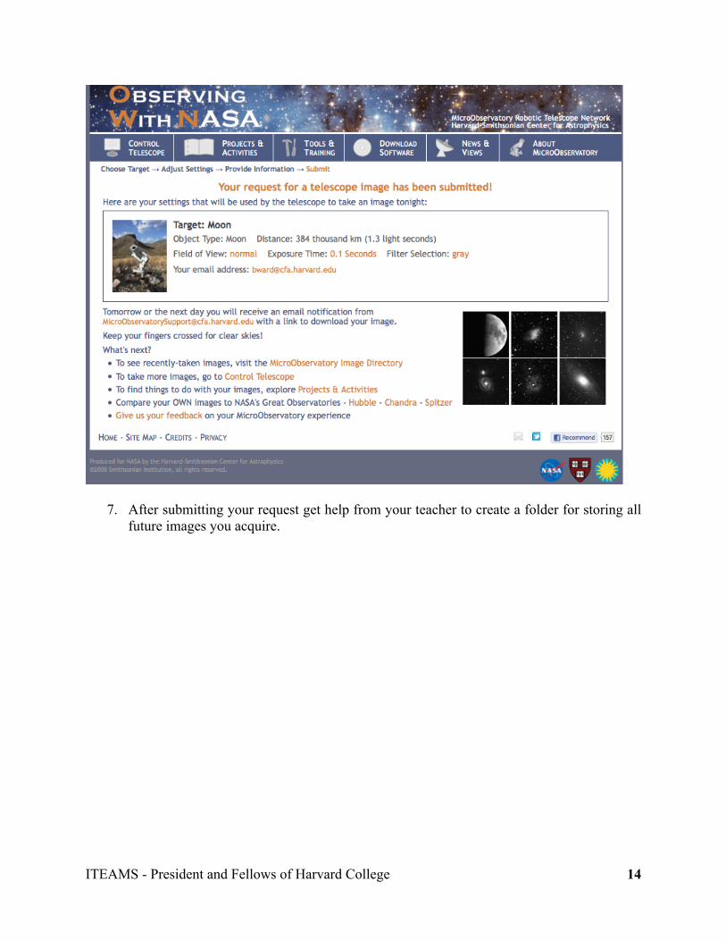
6. After completing your image request(s) a screen as below will appear indicating the
telescope settings to be used to take the image, along with some additional information about the targeted object (in this example the Earth’s moon).
ITEAMS - President and Fellows of Harvard College
14
7. After submitting your request get help from your teacher to create a folder for storing all future images you acquire.
ITEAMS - President and Fellows of Harvard College
15
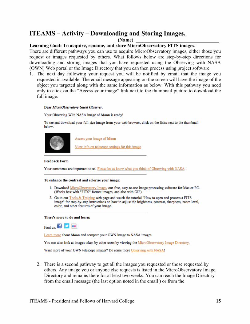
ITEAMS – Activity – Downloading and Storing Images. (Name) __________________________________ Learning Goal: To acquire, rename, and store MicroObservatory FITS images. There are different pathways you can use to acquire MicroObservatory images, either those you request or images requested by others. What follows below are step-by-step directions for downloading and storing images that you have requested using the Observing with NASA (OWN) Web portal or the Image Directory that you can then process using project software. 1. The next day following your request you will be notified by email that the image you
requested is available. The email message appearing on the screen will have the image of the object you targeted along with the same information as below. With this pathway you need only to click on the “Access your image” link next to the thumbnail picture to download the full image.
2. There is a second pathway to get all the images you requested or those requested by
others. Any image you or anyone else requests is listed in the MicroObservatory Image Directory and remains there for at least two weeks. You can reach the Image Directory from the email message (the last option noted in the email ) or from the

ITEAMS - President and Fellows of Harvard College
16
MicroObservatory home page as shown below (click on “Get Images” in the left hand sidebar).
3. The Image Directory window appearing below includes only a tiny portion of the images available. While they are listed by username, you can click on any of the other headings (“object” is the most useful) to sort and access any other images.
4. It does not matter if you use the prompt in your email or the directory to acquire an image, the window opening to the image will appear as below. The image shown is in GIF format; it can be dragged to your computer desktop or folder, renamed, and saved. It is strongly recommended, though, that you save the image in FITS format (which includes more data about the image). The best way to save a FITS image is to first open MicroObservatory Image (the link is on the MicroObservatory home page) on your computer, and then drag the file name to the open window and the image will open.

ITEAMS - President and Fellows of Harvard College
17
Alternatively, move the FITS file to your Downloads folder and then drag the icon for the file from that folder to the MicroObservatory Image open window.
5. The schematic that follows below provides a shorthand overview of two different ways to access images, either the specific image you requested or those in the Directory.
Your OWN Image Email
OWN Portal
Your Specific Image
Image Directory
Access “Your Image”
All Images
Full-Size GIF Image(Move to Desktop or to Image)
AccessAny Image
FITS Link (Move to Image or Folder)
6. You may process the image at this point (described in detail in the next activity), but first
you want to rename the file and save it in your own folder.
ITEAMS - President and Fellows of Harvard College
18
ITEAMS – Activity – Image Processing. (Name) __________________________________ Learning Goal: To process MircoObservatory images using MicroObservatory Image software. MicroObservatory Image software includes a wide range of tools you can use to process images acquired with the MicroObservatory telescopes. This includes tools to adjust image brightness and contrast, measure distances in pixels, and sharpen, crop, and false colorize. The software also includes tools to create full color images, discussed in detail in a following activity. 1. Open up MicroObservatoy Image with the link on the MicroObservatory home page
(http://mo-www.cfa.harvard.edu/MicroObservatoryImage/). Select the appropriate system (Mac or PC), and download and save the program to your computer if you have not done so previously. Open up the program on your computer.
2. As noted in an earlier activity, after selecting the image to be processed, it is best to drag
the FITS file to the open window of MicroObservatory Image where the image will open and it can be renamed and saved. If you have already saved the FITS file in a folder, move it to the open window as above.
3. The “Image Info” window will open in the top right corner (you can move it more to the
left); when you move the cursor over the image, pixel information is displayed in the “Image Info” window. First you can adjust for brightness and contrast of the image. Select “Adjust Image” under “Process” in the menu bar (Process/Adjust Image), and the “Adjust Image” window will also open at the top right corner (you can move it as well). Select “Linear” and “Auto” for a first look at the image (select “Reset” if you do not like the adjusted image). You can do the same with the “Log” button.
4. A next adjustment can involve the “pixel value” of the image. Move the cursor over the
image and observe how the “pixel value” is displayed in the “Image Info” window. Note the value for the dark regions and type that value into the “Min” box in the “Adjust Image” window. You need to press Return after any changes. Try the same for the “Max” box after scanning the bright regions. Try other values to see what combination of “Min” and “Max” gives the best image. You can also make similar adjustments using the log scale.
5. There is other information about your images under “Window” in the menu bar. The
“FITS Header” provides numerous details about the image, and the “Intensity Histogram” provides graphical data that can help you define the best “Min” and “Max” of an image when processing it.
6. There are other features to explore under the “Process” menu or selecting the icons
directly above the image. Under “Process” you can explore the effect on the image by changing its color, sharpening it, or reducing the noise. Note that “Sharpening” and “Reducing the Noise” are irreversible.
7. You may use the measuring tool above the image to determine the size in pixels for certain objects (e.g., craters on the Moon). The pixel length is displayed in the bar above
ITEAMS - President and Fellows of Harvard College
19
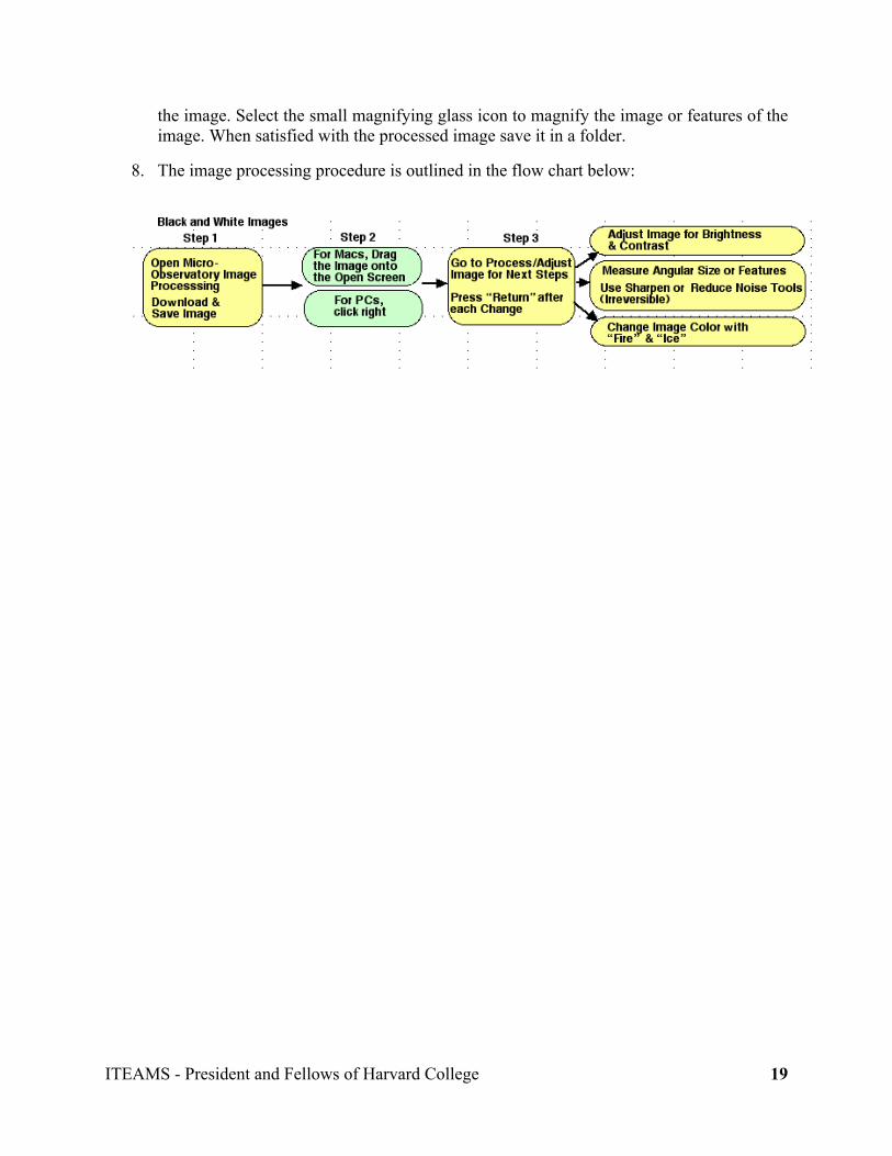
the image. Select the small magnifying glass icon to magnify the image or features of the image. When satisfied with the processed image save it in a folder.
8. The image processing procedure is outlined in the flow chart below:

ITEAMS - President and Fellows of Harvard College
20
ITEAMS – Exploration – Full Access with MicroObservatory. (Name) _________
Learning Goal: To learn how to directly control a MicroObservatory telescope.
Career Focus: Computer Programming, Engineering, Telecommunications, and Systems Designs.
Recording Your Ideas 1. If you could control a robotic telescope located hundreds of miles away using a computer, what instructions would you send to the telescope to take an image of an object in space? List them. ______________________________________________________________________________ ______________________________________________________________________________ Exploration 3 Procedure In addition to computer access you will need the following. ✔ Materials Checklist Email address Username Password for access Sky calendar or chart (Optional) Part 1. “Logging on the the MicroObservatory Website
1. Open your preferred browser and log on to the MicroObservatory Website at: http://mo-www.harvard.edu/MicroObservatory/. The screen below will open. Bookmark the site.

ITEAMS - President and Fellows of Harvard College
21
2. Select the “Full Access” prompt (third from left) and the screen below will open.
3. Locate the “Enroll” prompt in the left hand sidebar. Select “Enroll” and the screen below will open.

ITEAMS - President and Fellows of Harvard College
22
4. Select “Setting Up Your Guest Observer Account” and the screen below will open.
5. Enter the password you have been provided and follow the directions to complete your registration. Record your user name and password for future use (you may select to have this information “remembered” if you log on with your own personal computer).
6. Return to the MicroObservatory home page and select “telescopes” from the lefthand
sidebar and a screen similar to the one below will open.

ITEAMS - President and Fellows of Harvard College
23
7. Check the “Telescope Status” (in the menu above the map) to see which telescopes are ‘online’ and available for use. Place the cursor on the telescope location (the red dot indicates the location) to select a telescope to use. A screen similar to the one below will open (you may check the weather first if you wish by selecting “Local Weather” in the menu above the map).
8. Depending on the weather you may choose to take an image immediately or take it later. You may also select a telescope in another location if the sky is cloudy at the first location you chose. When you select “Yes, I will take an image now,” a screen that is two pages long will open. The first section – “Control Telescope” – is as below. Enter your user name and password.

ITEAMS - President and Fellows of Harvard College
24
9. Scroll down farther to “When To Take Image” and next to “Where To Point Telescope.” Select a time in hours and minutes to have the telescope take your requested image. (If, after completing the remainder of the request information, you are told the time you selected has been taken, you will need to re-enter a new time with all the other information. You can avoid this problem by selecting “View Queue” from the menu above the map and all the times requested will be listed.) Generally you will select the target object from the “Using List Below” menu. Select target objects from the list provided unless you are doing a special project.

ITEAMS - President and Fellows of Harvard College
25
10. The final steps are to select the camera (generally the Main Camera), the exposure time (from 0.05 seconds to 60 seconds), and a filter if one is to be used. The table that follows below provides information about suggested times and filters for getting images of different types of objects.
11. After selecting the exposure time and the filter – if one is to be used – select “Take Picture.” Do not alter the “Zoom” or “Focus.” Your image will be emailed to you in the morning. The full access procedure is outlined in the following flow chart.
Open Up TheMicroObservatoryWebsite & SelectFull Access Portal
Step 1 Step 2 Step 3 Step 4
Check theWeather &Select the Telescope
Select Telescopesfrom LeftSidebar
Select Time toTake Image
Select Target Object
Enter Username &Password
Select the Camera, Filter(s),& Take Picture
Step 5
Full Access Image Request

ITEAMS - President and Fellows of Harvard College
26
Quick Guide to Settings for the Telescope. Below are some suggested settings for taking images with MicroObservatory. These choices may not always be the best ones. You will find better settings for any given object by experimenting with different exposure times and filters.
Interpreting the Results 1. What do you think are the advantages of using a robotic telescope compared to a using telescope that you have to control in person? ____________________________________________________________________________ ____________________________________________________________________________ What I know about controlling a telescope hundreds of miles away using a computer…

ITEAMS - President and Fellows of Harvard College
27
ITEAMS – Activity – Creating Full Color Images. (Name) __________________________________ Learning Goal: To create a full color image from separate red, green, and blue filtered images of the same celestial object. It is possible to create a full color image of a celestial object using MicroObservatory Image software. You need to acquire three separate images of the object, one taken with a red filter, a second with a green filter, and the third with a blue filter. The images can then be combined using the procedure that follows. 8. Select a celestial object and get three images of the object–one each taken using the red,
green, and blue filters. If you have full access to the telescopes you can take the images yourself, or you can download them from the MicroObservatory Website. Nebulae and galaxies require a 60-second exposure time. The images need to have been taken in succession using the same telescope and settings.
9. When posted, download FITS images of each to MicroObservatory Image. The images you
access will be black and white, not colored. Open up the “FITS Header” under “Window” to see the color filter used with each image. Rename the images (identify which is red, green, and blue) and save them.
10. Follow the steps as described in the introductory imaging processing activity and adjust each image – one at a time – for brightness and contrast. You may want to adjust the “Min” so that each image has approximately the same lower value.
11. After you are satisfied with the adjustment for each of the images you need to colorize each one according to the color filter used when making a given image. Be certain to adjust each image for brightness and contrast before coloring them. Starting with the red-filtered image, select “Color Tables/Red” under the “Process” menu. Work with the green-filtered image and color it green in the same manner as with the red. Finally, color the blue-filtered image blue.
12. The next step is to align the images since they are likely to be slightly misaligned if you placed them one on top of another without any adjustment. You need then to align or shift the images so the combined image will not be blurred. Under the “Process” menu select “Shift.” As prompted, select one of your images (it is best to start with the green image) as the background image over which you’ll shift (i.e. align) the other two images. Then select an image to align; here it is generally best to select the red image for the first alignment. (You should see the background image through the slightly transparent foreground image.) Using the mouse, or the i.j.k.l keys as prompted, align the two images and then press the OK button. Once that image is aligned, repeat the procedure with the green background and the blue image. Press OK when the third image is aligned.
13. The last step is to “stack” or combine the images. Choose one of the images and under the “Process” menu select “Stack/Add Slice.” The label on top will now indicate “Stack.” Do the same for each of the other two images. The result will be what appears to be a single image. You can click on the arrows at bottom to see the red, green, and blue images individually.
14. Create the final color image by selecting “Stack/Convert Stack to RGB” under the “Process” menu. The red, blue, and green images are merged into the final image. Save the final image.

ITEAMS - President and Fellows of Harvard College
28
15. The process for combining images for full-color pictures is outlined in the flow chart below:

ITEAMS - President and Fellows of Harvard College
29
ITEAMS – Filters and the Colors You See.
(Name) _________ Learning Goal: To investigate the relationship of color to light.
Career Focus: Photography, Artistry, Television, Theater, Astronomy, Biology, and Video Production.
Recording Your Ideas 1. Colored filters only let certain colors pass through. What do you think you would see if you looked at red roses through a green filter? Explain your reasoning. Try it.
2. Suppose you looked at the red roses through a red filter – how would the roses now look to you? Explain your reasoning. Try it. _____________________________________________________________________________ _____________________________________________________________________________ Exploration Procedure Collect the following materials. ✔ Materials Checklist Digital camera with cable 5 Different-colored balls Colored filters (red, green, and blue) 3 Clothes pins Part 1. “Looking at Life Through All the Right Lenses” 1. Work with a partner. Predict what color each of the balls will appear to be when you look at them through each of the filters. Enter your predictions in the Table 1 below in the columns labeled “Prediction.” Predict which ball or balls will appear brighter when you look at them through each of the filters. Enter you predictions in the Table 2 below in the columns labeled “Prediction.”

ITEAMS - President and Fellows of Harvard College
30
Table 1. Predicted Apparent Color of Balls Viewed Through Filters Red Filter Green Filter Blue Filter Ball and Color Prediction Actual Prediction Actual Prediction Actual #1 #2 #3 #4 #5 Table 2. Predicted Brightest Appearing Balls When Viewed Trough Filters Red Filter Green Filter Blue Filter Ball and Color Prediction Actual Prediction Actual Prediction Actual #1 #2 #3 #4 #5 2. Attach a clothespin to the edge of each of the filters so you can use the clothespins as “handles” for holding each of the filters. 3. Look at the balls through each of filters and enter what you observe for each trial. Compare your observations to your predictions. Circle your predictions that were correct. What can you say about what color of light comes through each of the colored filters? ______________________________________________________________________ ______________________________________________________________________ Part 2. “How Things Stack Up” 1. Position the camera on a table so that you can take a picture of the balls placed in front of the camera. Mark the location of the camera. Do not change the location of the camera as you take pictures of the balls. 2. Place the different-colored balls in any arrangement you choose at the same distance from the camera. You can stack them or place them side-by-side. Be certain that all the balls are visible as you look through the camera. Adjust the location of the balls as necessary to be certain they are all visible in a single image or picture and appear to be the same size. 3. Take a picture of the balls. Examine the picture to be certain all the balls are clearly visible. If the balls are not all clearly visible take a second picture. If necessary, continue until you have a satisfactory picture. 4. Place one of the filters in front of the camera lens and take a picture of the balls. Examine the picture to see that it is satisfactory. Label it and transfer the picture to a computer. Take pictures of the balls using the other two filters, and then label and transfer them to a computer.

ITEAMS - President and Fellows of Harvard College
31
5. Follow the directions of your teacher to process the images. What you will do is “stack” or combine the three pictures you took of the colored balls with the red, green, and blue filters into a single picture. Interpreting the Results 1. Look back at the pictures you took using the three filters. How did each of the pictures you took with the filters compare to the observations you made in Part 1? _________________________________________________________________________ _________________________________________________________________________ 2. Describe what happened when you combined (stacked) the images taken through the red, green, and blue filters into a single image. _________________________________________________________________________ _________________________________________________________________________ What I know about how combining images of objects taken through red, green, and blue filters can give the actual colors of the objects…

ITEAMS - President and Fellows of Harvard College
32
ITEAMS – Distance, Size, and Scale I.
(Name) _________
Learning Goal: To compare the apparent size of like-sized balls at different distances.
Career Focus: Biologist, Artist, Architect, Airline Pilot, Race Car Driver, Engineer, Chemist.
Recording Your Ideas 1. In the picture below can you tell if object A is the same size as object B, or a different size? Explain your reasoning.
2. Suppose the objects were all the same size – what would that tell you about the distance to object B compared to object A? Explain your reasoning. ____________________________________________________________________________
____________________________________________________________________________
Exploration Procedure Collect the following materials. ✔ Materials Checklist Digital camera with cable 5 Same-sized balls of different colors Piece of chalk or masking tape Meter stick Small ruler Part 1. “Putting All Your Eggs in One Basket” 1. Work with a partner or partners as instructed by your teacher. Position the camera on a table so that you can take a picture of the balls placed in front of the camera. Mark the location of the camera with chalk or a piece of masking tape.
A
B

ITEAMS - President and Fellows of Harvard College
33
2. Select the 5 same-sized balls of different colors and place them on a table at different distances from the camera. Be certain that all the balls are visible as you look through the camera. Adjust the location of the balls if necessary to be certain they are all visible in a single image or picture. 3. Take a picture of the balls. Examine the picture to be certain all the balls are clearly visible and do not appear to touch one another. If the balls are not all clearly visible, or if they appear to touch one another, take a second picture. If necessary, continue until you have a satisfactory picture. 4. Use the meter stick to measure the distance from the front of the camera to each of the balls. Record the values in the following table: Ball and Color Distance from Camera (cm) #1 #2 #3 #4 #5 5. Make a “birds eye view” of the arrangement of the balls on the table top for the best picture.
6. Transfer the picture to a computer for your classmates to duplicate. If possible, use a printer to make a paper copy. Take apart the arrangement of balls before the next team takes your place. Part 2. “Anything You Can Do, I Can Do Too” 1. Examine the picture made by your classmates for Part 1. Work with the same-sized balls and arrange them so they look like the pattern in the picture made by your classmates. 2. Take a picture of the arrangement you created and compare your picture to that made by your classmates. Adjust the location of the balls as necessary until you feel confident the picture you take matches that of your classmates. 3. Use the meter stick to measure the distance each ball is from the front of the camera. Record the values in the following table:
Ball and Color Distance from Camera (cm) #1 #2

ITEAMS - President and Fellows of Harvard College
34
#3 #4 #5 4. Obtain the data recorded by your classmates for Part 1 and compare it to the data you derived. How close were your results to the data from your classmates? __________________________________________________________________________ __________________________________________________________________________
Interpreting the Results 1. Look back at the picture at the beginning of this exploration. What would you need to know about the objects to determine if they were all the same size? Explain. ____________________________________________________________________________ ____________________________________________________________________________ ____________________________________________________________________________ 2. Look at your data from Part 1 and identify one of the balls that is about two times farther from the camera than one that is closer. Look at the picture you took. What can you say about the apparent size of the closer ball to the apparent size of the ball about twice as far away? Measure the diameters of the balls in the picture and compare them. About how many times bigger is the apparent size of the closer ball to the ball that is about twice as far away from the camera? ____________________________________________________________________________ ____________________________________________________________________________ ____________________________________________________________________________ What I know about distance, size, and scale…

ITEAMS - President and Fellows of Harvard College
35
ITEAMS – Distance, Size, and Scale II.
(Name) _________ Learning Goal: To compare the apparent size of different-sized balls at different distances.
Career Focus: Engineer, Astronomer, Physician, Automobile Mechanic, Carpenter, and Surveyor.
Recording Your Ideas 1. In the picture below are three common sports balls – a basketball, pool ball, and baseball. Can you tell if all the objects are the same distance away from the camera, or at different distances? Explain your reasoning.
2. Suppose the objects were all the same distance away from the camera – how, if at all, would that change the way the picture looks? Explain your reasoning. ______________________________________________________________________________ ______________________________________________________________________________
Exploration Procedure Collect the following materials. ✔ Materials Checklist Digital camera with cable 4 or 5 Different-sized balls Meter stick Small ruler Part 1. “Looks Can Be Deceiving” 1. Work with a partner or partners as instructed by your teacher. Position the camera on a table so that you can take a picture of the balls placed in front of the camera. Mark the location of the camera. 2. Select the different-sized balls and place them on a table at different distances from the camera so they will all appear to be the same size. Be certain that all the balls are visible as you look through the camera. Follow your teacher’s instructions so the mid-point of each ball is about the same height off the table. Adjust the location of the balls as necessary to be certain they are all visible in a single image or picture and appear to be the same size.

ITEAMS - President and Fellows of Harvard College
36
3. Take a picture of the balls. Examine the picture to be certain all the balls are clearly visible and do not appear to touch one another, and they all appear to be the same size. If the balls are not all clearly visible, if they appear to touch one another, of if they do not appear to be the same size, take a second picture. If necessary, continue until you have a satisfactory picture. 4. Use the meter stick to measure the distance each ball is from the front of the camera. Record the values in the following table: Ball and Size Distance from Camera (cm) #1 #2 #3 #4 #5 5. Make a “birds eye view” of the arrangement of the balls on the table top for the best picture.
6. Transfer the picture to a computer for your classmates to duplicate. If possible, use a printer to make a paper copy. Take apart the arrangement of balls before the next team takes your place. Part 2. “Again, Anything You Can Do, I Can Do Too” 1. Examine the picture made by your classmates for Part 2. Work with the different-sized balls and arrange them so they look like the pattern in the picture made by your classmates. 2. Take a picture of the arrangement you created and compare your picture to that made by your classmates. Adjust the location of the balls as necessary until you feel confident the picture you take matches that of your classmates. 3. Use the meter stick to measure the distance each ball is from the front of the camera. Record the values in the following table: Ball and Size Distance from Camera (cm) #1 #2 #3 #4 #5

ITEAMS - President and Fellows of Harvard College
37
4. Obtain the data recorded by your classmates for Part 2 and compare it to the data you derived. How close were your results to that of your classmates. _________________________________________________________________________ _________________________________________________________________________ Interpreting the Results 1. Look back at the picture at the beginning of this exploration. What would you need to know about the objects to know for certain they were all different sizes? Explain. _________________________________________________________________________ _________________________________________________________________________ 2. Look at the arrangement of balls you created in Part 1 and identify one ball that is about two times larger than a second ball. How far away from the camera is the larger ball compared to the smaller ball? What do you predict they would look in a picture if they were both the same distance from the camera? Try it. Measure to see if your prediction was accurate? _________________________________________________________________________ _________________________________________________________________________ _________________________________________________________________________ What I know about distance, size, and scale…