isv pressure asme b16.11, b16.34 code compliant material ... · temperature: fahrenheit isv series...
TRANSCRIPT

TEMPERATURE: FAHRENHEIT
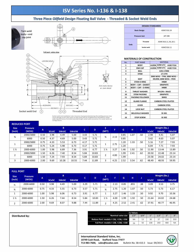
ISV Series No. I-136 & I-138
Three Piece Oilfield Design Floating Ball Valve Three Piece Oilfield Design Floating Ball Valve
Threaded & Socket Weld Ends, 2000 Threaded & Socket Weld Ends, 2000 -- 6000 WOG6000 WOG
DESIGN & PRODUCTION FEATURES
· 3 Piece Forged Body · API 607 5th Ed. fire safe tested,
ASME B16.11, B16.34 code compliant · Pressure tested to API 598 · All valves with 316SS ball and 17-4 PH Stem · All valves with heavy duty locking lever · Tack weld body joint prevents unintended
disassembly during installation · Meets NACE · Full and Reduced Ports designs
PRESSURE RATING: 2000 PSIG @ 100°F W.O.G. – A105N & LF2 body 3000 PSIG @ 100°F W.O.G. – A105N & LF2 body 6000 PSIG @ 100°F W.O.G. – A105N & LF2 body
ISV HOW TO IDENTIFY ISV Series I-136 & I-138 Forged 3pc body Oilfield Floating Ball Valves
PRESSURE - TEMPERATURE CHART (limits of seat & seal materials)
PEEK HNBR DELRIN
TFM 4215
psi
Threaded end configuration Socket weld end configuration
is a registered trademark of International Standard Valve, Inc.
I ₋ 2 3 8 ₋ 3 ₋ F H ₋ T H
Figure Number Example: I-238-3-FH-TH
Describes a 3000 psi WOG, 3 piece oilfield
design, floating style ball valve, full port,
LF2 body with Delrin seats, HNBR seals,
threaded end connections. Ball of 316SS
is standard, 17-4 PH stem is standard,
with locking lever operator.
ISV Series
Material Design Port Pressure
Rating Seats Seals End Connection
I
1
3
6
2
C V
TH ISV
Design
A105
Forged Oilfield Design
Reduced
2000WOG
TFM 4215
Viton
Threaded female
2
8
3
F H
SW
LF2
Full
3000WOG
Delrin HNBR
Socket Weld
3
4
N L
ST
F316SS
4000WOG
Nylon (Low temp elastomers)
SW X TH female
6
P
6000WOG
PEEK
MATERIALS OF CONSTRUCTION
REDUCED PORT
FULL PORT
Three Piece Three Piece Oilfield Design Oilfield Design Floating Ball Valve Floating Ball Valve -- Threaded & Socket Weld EndsThreaded & Socket Weld Ends
International Standard Valve, Inc. 10749 Cash Road, Stafford Texas 77477 713-983-7600, [email protected] Bulletin No. SB-410.3 Issue 09/2013
Size (inch)
Pressure (WOG)
A B
C D E
(NPT) F G H J
Weight (lbs.)
SCxSC SWxSC SWxSW SCxSC SWxSC SWxSW
¾ 2000/3000 0.50 3.98 4.49 5.00 3.43 5.71
¾ 2.13 0.85 1.07 .50 2.98 4.41 5.07
6000 0.50 4.37 4.69 5.00 3.43 5.71 0.85 3.42 4.63 5.07
1 2000/3000 0.75 4.33 5.53 6.73 4.17 5.71
1 2.75 1.20 1.33 .50 5.16 7.27 7.93
6000 0.75 5.24 5.98 6.73 4.17 5.71 1.20 6.04 7.71 7.93
1 ½ 2000-6000 1.00 5.98 6.89 7.36 3.91 6.77 1 ½ 3.27 1.46 1.92 .50 11.90 13.44 13.89
2 2000/3000 1.50 6.26 7.40 8.54 5.84 10.83
2 4.00 1.99 2.41 .62 20.50 22.48 23.14
6000 1.50 7.24 7.93 8.54 5.84 10.83 1.99 23.58 24.02 23.14
3 2000-6000 2.00 9.69 10.28 10.55 7.44 11.89 3 4.25 2.52 3.54 .62 48.49 48.93 59.95
Size (inch)
Pressure (WOG)
A B
C D E
(NPT) F G H J
Weight (lbs.)
SCxSC SWxSC SWxSW SCxSC SWxSC SWxSW
½ 2000-6000 0.50 3.98 4.49 5.00 3.29 5.71 ½ 2.13 0.85 .855 .38 3.09 3.53 3.75
¾ 2000-6000 0.75 4.33 5.55 6.73 3.57 5.71 ¾ 2.75 1.20 1.07 .50 5.73 5.73 6.17
1 2000-6000 1.00 5.98 6.06 6.73 3.91 6.77 1 3.27 1.46 1.33 .50 9.92 9.70 10.36
1 ½ 2000-6000 1.50 6.26 7.44 8.54 5.84 10.83 1 ½ 4.00 1.99 1.92 .50 21.64 24.02 24.68
2 2000-6000 2.00 9.69 8.07 9.88 7.44 11.89 2 4.25 2.52 2.41 .62 37.91 40.77 46.95
ISV Series No. I-136 & I-138
Distributed by:
Full port valve view
Anti-static device at stem detail
No. PART NAME MATERIAL 1 BODY A105N A350 LF2 A182 F316 2 END CAP A105N A350 LF2 A182 F316 3 BALL A351 CF8M 4 STEM 17-4 PH
5 SEAT 2000 WOG – TFM; 3000 WOG –
DELRIN; 6000 WOG – PEEK 6 STEM O-RING HNBR 7 BODY – CAP – GASKET GRAPHITE 8 BODY – CAP – O-RING HNBR
9 THRUST WASHER NYLON + MoS2 10 STEM PACKING GRAPHITE 11 PACKING FOLLOWER 304SS
12 GLAND FLANGE CARBON STEEL PLATED
13 LEVER CARBON STEEL
14 LOCK NUT CARBON STEEL PLATED
15 BELLEVILLE WASHER SS 301
16 STOP SCREW SS 302
Socket weld End Threaded End
DESIGN STANDARDS
Basic Design ASME B16.34
Pressure test API 598
Ends
Threaded ASME B16.11, B1.20.1
Socket weld ASME B16.11
Tack weld body—end
cap joint
Socket weld end installation note: Excessive heat generated during the welding process may cause damage to the valve seats of valve ends that are modified from threaded to socket weld. Specify factory furnished extended length socket weld connection for socket weld end configurations.
Cv Values
Nominal valve size 1/2” 3/4” 1” 1.5” 3” 2”
Reduce Port: models I-136, I-236, I-336 NA 13 30 37 350 100
Full Port: models I-138, I-238, I-338 26 50 108 260 NA 480