ist-2000-30082 ida-step
TRANSCRIPT

1 / 40
IST-2000-30082 IDA-STEP
Integrating Distributed Applications on the Basis of
STEP Data Models
Document link to project
Deliverable D24
Document title Final Report, public
Originator: Robert Rech EDAG Engineering & Design AG, Germany
Lothar Klein, LKSoftWare GmbH, Germany
Rolandas Randis, Tomas Baltramaitis, Vaidas Nargelas UAB LKSoft Baltic, Lithuania
Document History
Version Date Status Evolutions Responsible person/organization
1.0 2004-06-03 Final Created see above
Copyright © 2004, EDAG Engineering & Design AG, LKSoftWare GmbH

2 / 40
1 Executive Summary _____________________________________________3
2 Foreword______________________________________________________ 4
3 Project Summary _______________________________________________6 3.1 Abstract:________________________________________________________6 3.2 Objectives: ______________________________________________________6 3.3 Work description: ________________________________________________6 3.4 Milestones:______________________________________________________7 3.5 Project Details ___________________________________________________8 3.6 Major changes during the project ___________________________________8
4 Motivation and Business Use Cases _______________________________ 9 4.1 Classification to common PDM-Solutions_____________________________9 4.2 IDA-STEP as integration platform for different tools in engineering
processes_______________________________________________________9 4.3 IDA-STEP for the cooperation in distributed development processes _____11 4.4 IDA-STEP as communication platform between engineering process and
commissioning/on site ___________________________________________13 4.5 IDA-STEP for the integration of of mechanical and electrical data ________14 4.6 IDA-STEP as basis for system neutral long- time archiving _____________15 4.7 IDA-STEP as resource library in production development process _______16
5 Major Technical Results_________________________________________18 5.1 JSDAI _________________________________________________________18
5.1.1 3D Viewing _______________________________________________20 5.1.2 STEP 3D Geometry ________________________________________20 5.1.3 VRML support_____________________________________________21
5.2 STEP-Book_____________________________________________________21 5.3 IDA-STEP schema (AP214+AP212+AIM) _____________________________22 5.4 IDA-STEP Center and IDA-STEP Viewer _____________________________24 5.5 Kinematic ______________________________________________________26 5.6 2D Layout and technical Drawing___________________________________27 5.7 Process Plan converter and Viewer _________________________________30 5.8 EPLAN 5 – AP212 Converter and Viewer_____________________________30 5.9 STEP – PDM Integration __________________________________________33 5.10 Data merging ___________________________________________________33 5.11 PDTnet services_________________________________________________35
6 Test Scenarios ________________________________________________36
7 Lessons Learned ______________________________________________38
8 Outlook and Commercialization __________________________________38
9 References ___________________________________________________39

3 / 40
1 Executive Summary
STEP (ISO 10303) is a major standard for exchange and integrat ion of industrial product data. The application protocols AP214 on automotive design and AP212 for electrical design and installation are major parts of STEP.
Exchange and integration of design data between different systems and organizations is typically a rather tedious, error prone and expensive process. STEP can help to drastically reduce these costs. Traditionally vendors of CAD/CAM/PDM systems are not too much engaged in implementing and driving forward neutral standards on data exchange. Therefore the capabilities of STEP are used today only to a small degree.
The main goal of the IDA-STEP project was to review, implement and use STEP AP214 and AP212 capabilities in a much wider scope. A special focus was on realizing concepts of the digital factory for the body in white assembly of cars.
The main outcome of the IDA-STEP project are
• STEP is suitable for integrating different applications of the digital factory development process. This has been successfully demonstrated on a production line for the body in white assembly of cars.
• Various improvements and fixes on several parts of the STEP standard.
• First public examples and guidance on how to use STEP for the digital factory.
• The software prototype IDA-STEP for viewing, editing and integrating of STEP data in a STEP database for multi user access via Internet, including handheld devices.
The IDA-STEP project has been partly funded by the IST program of the European Commission. Beyond the end of the project a cooperation between LKSoft, EDAG and ASM are deploying the software results of IDA-STEP.
Trademarks:
IDA-STEP and JSDAI are registered trademarks of LKSoftWare GmbH. eM-Planner is a registered trademark of Tecnomatix. CATIA is a registered trademark of Dassault Systèmes. Teamcenter and Unigraphics are registered trademarks of UGS. eM-Planner is a registered trademark of Tecnomatix. eMatrix is a registered trademark of MatrixOne. AutoCAD and Inventor are registered trademarks of Audodesk. SolidWorks is a registered trademark of SolidsWorks Corporation. Pro/ENGINEER is a registered trademark of Parametric Technology Corporation. Java is a registered trademark of Sun Microsystems Inc.

4 / 40
2 Foreword
In the past 10 years the automobile industry invested a lot of resources into the development of the STEP-AP214 standard. This was an internationally wide effort mainly driven by the car OEMs in Japan, USA and Europe and also by several public funded projects. In parallel to the development of the standard also some prototype implementations where developed. But many of them did not make it into commercial applications. Among others some main reasons for this are
- The STEP standard is more complicated than is needs to be, e.g. the ARM-mapping-AIM approach
- Due to the complexity of the STEP standard it had many errors, which had to be fixed first.
- The STEP Standardization failed to give "good" and complete examples of the usage of the standard, needed for developing further converters. Available recommended practises covers only a small part of the stand ard.
- Tutorials on a detailed technical level are missing. Only insiders (people participating directly in the standardization) were able to implement the standard.
- The available tools to work on STEP where not at a level as they are today, so implementations had to fight with many additional problems
- The internal data models of the CAx/PDM/EDM systems where not harmonized with AP214.
Since the automotive industry did no see the needed Return Of Investment (ROI) of the spent money, new activities into STEP where strongly decreased. This was the situation at the beginning of the IDA-STEP project.
Nevertheless STEP-AP214 is still the only standard for data exchange within the automotive industry. Many of the problems listed above where solved and we think we can say that the IDA-STEP project played a significant role in the overall improvements of AP214 and its implementation:
- Many bugs in various part of the STEP standard were fixed. This leads to a second edition of AP214, available from ISO.
- Tools were developed to overcome the complexity problem of STEP (e.g. the ARM-AIM-mapping technology of LKSoft - thanks to IDA-STEP).
- Public example files become available
- The free software tool IDA-STEP Viewer for end users to view STEP AP203, 212, 214 and PDM-schema data.
- IDA-STEP Center allowing to create and edit STEP-PDM data
- Various converters for CAx and PDM systems (EPLAN5, MicroStation, CATIA v4, eM-Planner, eMatrix, Teamcenter Engineering)
At the beginning of the IDA-STEP project (early 2001) STEP data exchange was already mature in the area of 3D geometry between several Mechanical CAD-Systems. However in other areas STEP data exchange was only in use for pilot projects, in some very specialized customer-vendor scenarios, or not in use at all. One could easily verify this statement by searching for public STEP example files. To find them for 3D geometry and assembly was not a problem at all, in the basic PDM area it was already rather difficult and in other areas it was almost impossible to find any valid and actual STEP example file. It seems that most of the early STEP pilot
5 / 40
projects running several years before vanished without any remaining visible results – except for the fact that the STEP standard was developed. One of the major reasons for this is obviously the fact that the development and final standardization of most parts of STEP took much longer than originally expected. What was finally standardized is not compatible to what was implemented in early pilot projects. So these results were lost. We can see this with practically all results given in the AP212 and AP214 Validation report, and the results of the InterRob project. Also the formal test examples for AP212 and 214 (ATS 314, ATS 312) are outdated, invalid and in no way relevant. This is the reason why those ATS parts were removed from the ISO work program.
On the other hand we have to see that formal validation of STEP files against all the rules given in the Express schemas is only possible since the year 2000 (about). Before many of the rules in STEP- Express schemas were broken and Express implementations were not ready to do all the needed validation. So this was an iterative process between standard developers and Express tool implementors. Only today we can say that the rules in STEP Express schemas are stable and can really be validated in all aspects.
One main goal of this project was to bring STEP-Data exchange beyond the 3D area into reality and drive it further into areas not yet really addressed. In the PDM area several organization and systems are now ready for data exchange based on STEP, such as:
- MatrixOne / eMatrix at EDAG
- EDS-UGS / Teamcenter Engineering at EDAG
- Smaragd at Daimler Chrysler
- Dassault / VPM at Airbus
- STAMP project at ATI, USA
The IDA-STEP project was not able to address all problems of the STEP standard.
- Relations between aspects of the shape of a product (e.g. the multi-model links of CATAI v5)
- Geometric and Dimensional Tolerances (GD&T)
- STEP AP214 do not cover history and parametrics of geometry models. Currently activities are going on to include this – at least partly – into the second edition of AP203.
It can be observed that the data structure of new versions of the used CAx/PDM/EDM system are today much closer in line with STEP as it was years ago. This allows much more efficient STEP translators and data exchange between different partners.
6 / 40
3 Project Summary
Below you will find the original project summary, updated for changes happen during the project lifetime.
3.1 Abstract:
STEP (ISO 10303) is the international standard for the exchange of industrial product data. AP214 is a part of STEP for "Automotive Design". It is well suited to be the integration backbone to realize the concept of a "digital factory". Within this project AP214 as well as AP212 "Electrical Installation" is used for the body in white assembling of cars and the needed production facilities. Data from the engineering, design and try out phase is integrated in STEP compliant databases and linked with various CAx tools and an EDM system. The data is made network accessible in read and write mode for various usages and users in parallel. To keep the solutions platform neutral the Java programming language is used throughout the project. Data formats, suitable for Internet communication such as XML, VRML, Java Remote Method Invocation (RMI), including Java object serialization, and also the Microsoft COM interface are used to link CAx and PDM systems and other end -user tools with the integrated STEP database. This data is made available on handheld devices for wireless end user access.
3.2 Objectives:
The objective was to integrate and organize the data flow for the planning of production facilities. For this, data, collected at different stages of the design, starting from the requirement phase till the final production are integrated in databases, organized according to STEP data models, mainly ISO 10303-214 "Automotive Design" and ISO 10303-212 "Electrical design and installation". Integration mechanisms for existing non-STEP based database architectures and CAx-applications are developed. Since customer, designer, manufacturer and installation location are on different places, the integrated data is made fully accessible through network access. For this data is made available in various formats: from worked up HTML/XML representations for web-browsing in simple computers and handheld devices up to fully detailed formats for CAx-Systems. The results of this project are verified with concrete turnkey project from the empty factory hall to the complete body shop and assembly system for the series production of cars.
3.3 Work description:
This project is based on existing STEP technologies. The underlying framework for the software development is JSDAI, an SDAI implementation (ISO 10303-22) for the Java programming Language (ISO/TS 10303-27:2000) with High Level ARM-to-AIM extension, a 3D-viewer and a universal database representation (SQL) for STEP data. This project integrated network accessible data according to STEP-AP214/212 data models, in particular: ·
• PDM information; ·
• classification systems; ·
• specification control for variants; ·

7 / 40
• process planning; ·
• electrical cabling; ·
• schematic drawings; ·
• 3D geometry models with kinematic
Platform neutral software solutions were developed: ·
• EXPRESS-X to "map" formally between different data representations and to define ""views"" on them; ·
• Intelligent Schematic Drawings (2D) linked with product structure and product properties; ·
• 3D viewing with kinematics features; ·
• configurable tools to merge STEP exchange files with STEP databases and EDM systems; ·
• light-weight STEP implementations for network enabled handheld devices;
• XML – PDTnet server to access the integrated information via web-browser and third party PDTnet clients.
These software results were used to realize a "digital factory". A special focus was on different design views of the car body and the production equipment, together with the linking process plan information. The backbone of the digital factory is the STEP based documentation. This data is made network accessible for all partners and systems in the development and production process, starting from the early requirements of the customer, a first design version from the vendor, to the detailed process design with simulation results and variant support up to the fabrication, installation and try out of the production equipment. All this data is made available at different locations, for different users and various systems.
3.4 Milestones:
1. Complete integration of the data of a digital factory in STEP-AP212/214 compliant databases. This data covers the engineering, design, and try-out phase of production equipment for the body in white assembling of cars;
2. Linking STEP databases with the eMatrix EDM system based on the EDAG data model;
3. Making the integrated STEP-AP212/214 data available on handheld devices for end-user access via wireless network connection;
4. Making STEP databases available for network enabled tools via XML.

8 / 40
3.5 Project Details
Project web site: http://www.ida-step.com and http://www.ida-step.net
Start Date: 2001-08-01 End Date: 2004-03-31 Duration: 32 months
Project Cost: 1.14 million €, Project Funding: 569999.00 €
Programme Acronym: ISTProgramme Type: 5th FWP (Fifth Framework Programme) Subprogramme Area: Computing, Communications and Networks - Distributed systems and services provision Contract Type: CSC (Cost-sharing contracts)
Subject Index: Information Processing, Information Systems; Innovation, Technology Transfer; Telecommunications
Participating organizations:
• EDAG Engineering & Design AG, Reesbergstraße, http://www.edag.de
• ASM DIMATEC S.A., Reus, Spain, http://www.asmgrupo.com
• FFT Espana Technologies de Automocion, S.A.Contact, Silla (Valencia), Spain
• LKSoftWare GmbH, Kuenzell, Germany, http://www.lksoft.com
• Zamisel Programiranje, D.O.o., Preserje, Slovenia, http://www.zamisel.com
• UAB LKSoft Baltic, Kaunas, Lithuania, http://www.lksoft.lt
3.6 Major changes during the project
Originally it was planned to implement PDM-Enabler within this project. But since the extended and harmonized draft of version 1.2 of PDM-Enabler was not finished by OMG the IDA-STEP consortium decided to abandon this activity and implement instead PDTnet.
Another major change happens with the Express-X implementation and usage for converters. A first version of the process plan converter was written using Express-X. But it become clear that using Express-X for such a converter results in rather complicated Express-X code which is hard to maintain and which has significant performance problems. Therefore the decision was taken to write such converters using the Early Binding of JSDAI on the ARM level and use the ARM -AIM mapping tool to link with the normative AIM level for data exchange.

9 / 40
4 Motivation and Business Use Cases
4.1 Classification to common PDM-Solutions
Analogy: What is the difference between a bus and a train?
The question is conferrable to the difference between IDA- STEP and common PDM tools.
Traditional PDM- systems are comparable with a train that is limited to a specific rail system. A train is an established means of transportation for transportation of a multiplicity of people and goods. The efficiency of transportation is dependent on well developed infrastructure with a comprehensive maintenance and care. The adaptation of services on changed boundary conditions is a complex process and efforts a central
and overall planning. Nevertheless rail systems have been established way long before modern streets.
In comparison to a train a bus is de-central means of transportation. Its infrastructure is s imultaneously used by many different independent traffic participants. Synchronal business processes are not necessary to parallel operate the busses from different parties. The standardized infrastructure ‘street’ is analogical comparable to the standard STEP.
Conclusion: IDA-STEP principally offers a service which similar to traditional EDM/PDM systems. The demand of small and medium sized companies (SME) to fast and flexible adapt to changed boundary conditions is guaranteed by IDA-STEP with less organizational requirements. The effort to operate a bus in comparison to a train and its rail system is less effort.
4.2 IDA-STEP as integration platform for different tools in engineering processes
Motivation Main reason why software becomes dated and obsolete is not that it ‚wears out’. It often rather fails due to adaptation to its changing environment.
An integration with new applications and its developing technology is not often working out as more effort of development is invested into internal structures of the program rather than into interfaces of the program to the rest of the world. [D. Curtis: "Java, RMI and CORBA“, Object Management Group (OMG) White Paper, http://www.omg.org/news/wpjava.htm, 1997].
10 / 40
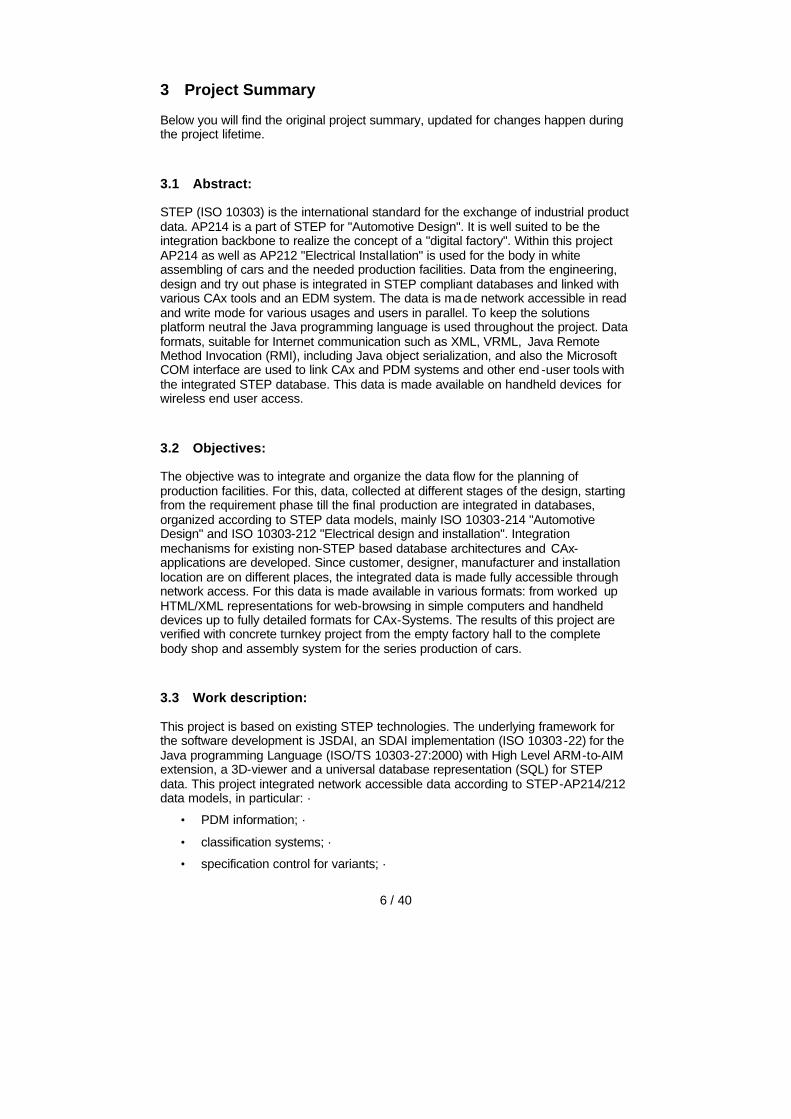
The automotive development process is supported by a multiplicity of specific software tools. Different tools and process steps always require the same basic information. The geometrical description, the structure as well as specific features of the product and production equipment are repeatedly used and enhanced as input parameters during product development. At present the transfer of the basic information often takes place manually or with specific interfaces (proprietary) between the systems. This leads to high administrative efforts, to failure risks and to a high percentage of non- effective activities.
Compared to proprietary interfaces, i. e. bilateral system specific interfaces between two systems, on the basis of STEP a common bi-directional interface is required with a connection to each system (n) instead of a bi-directional interface with a connection to other systems (n*n). Furthermore, the addition of a additional system when using a standard interface only one new connection to the common interface is required instead of n new interfaces. The previous interface (in ideal case) stays completely unchanged resp. is enhanced without modifying the existing part.
Solution of IDA- STEP The focus of the solution IDA-STEP lies on the process for development of production plant for automotives.
Today first concrete planning steps for the automotive production are supported in layout and process planning tools. Geometry, structure and features of the product to be manufactured are important input parameters for this process step. This product information is taken over from different EDM/PDM - system via STEP.
The STEP based connection of the process planning tool eM -Planner allows to automatically takes on the product description. Within process planning production specific views on production information, quantity structure for required production equipment (resource tree) as well as description of process steps for manufacturing of product are developed. All these information can be transmitted from process planning tools via STEP to parallel and following steps of development process. So, e.g. the resource structure incl. contents of layout can be synchronized.
11 / 40
The STEP based interface to the layout CAD system MicroStation enables the possibility to identify and describe components in the layout. In IDA-STEP components can be structured. Furthermore, it enables the possibility to take over AutoCAD DXF files to the STEP standard.
The detailed description of geometry and structure of production equipments take place at the end of planning process with different CAD- systems. In IDA-STEP the results of detailed phase can be administrated with regard to the results of planning phase in an integrated structure. Hereunto import routine are made available. The import routines enable a smooth take over of STEP export data from CAD systems CATIA (Version 4 and 5), Pro/ENGINEER and Unigraphics as well as AutoCAD Inventor and SolidWorks.
4.3 IDA-STEP for the cooperation in distributed development processes
Motivation The use of data management tools for support of development processes is permanently increasing. Precursors are automotive manufacturers. Also many big -sized supplier already support their process with EDM/PDM solutions. The use of EDM/PDM enables to provide CAx models with additional information to control the working process (responsibilities, status information, validity, etc.). In EDM/PDM system assembly structure information and further relations are represented. The information firstly supports the workflow from area of use of the EDM/PDM s ystem.
To transfer the information to the partners, involved in development process, required documents are exchanged or are encoded in the CAD model names. Both possibilities are vulnerable to failures and produce redundant inefficient activities.
Solution of IDA-STEP The standard STEP opens an alternative to above-mentioned methods. Many automotive manufacturers and suppliers already support the exchange of STEP data structures. At this the conversion of CAD models into the neutral STEP format for geometry description is not main focus. In fact original geometry formats are kept, only dependent information and relations between models in STEP format are in focus.
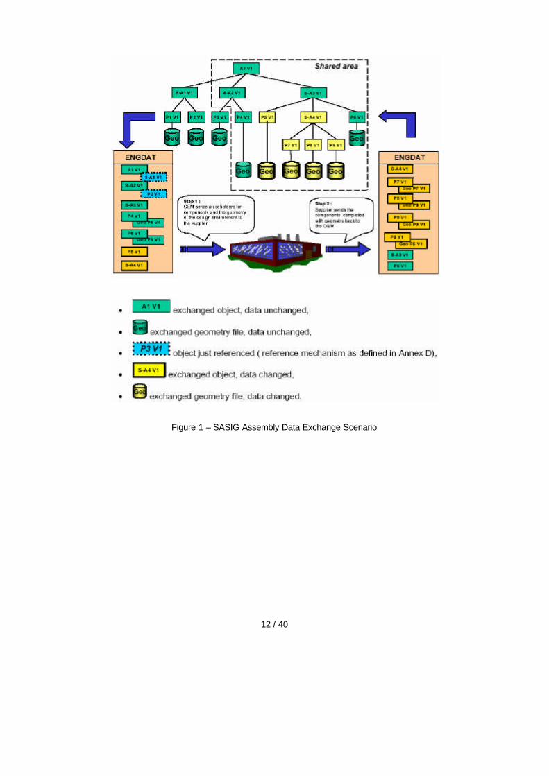
IDA-STEP enables the import and handling of these structures. It can be indicated which partial structures are to be modified and which are read-only and supplied for references. Also information on maturity of dataset and its author and responsible person are commonly administrated by EDM/PDM systems. The information can be transported to the development partners for their individual development processes via STEP/IDA-STEP.
The international consortium SASIG (Strategic Automotive Product Data Standards Industry Group) is an association of many important automotive manufacturers and some big suppliers. SASIG has worked out a reference for the exchange of assembly structures in distributed development environments, which is fulfilled by IDA-STEP.
The SASIG “Assembly Data Exchange specification” illustrates such an exchange scenario along this picture:
12 / 40
Figure 1 – SASIG Assembly Data Exchange Scenario
13 / 40
4.4 IDA-STEP as communication platform between engineering process and commissioning/on site
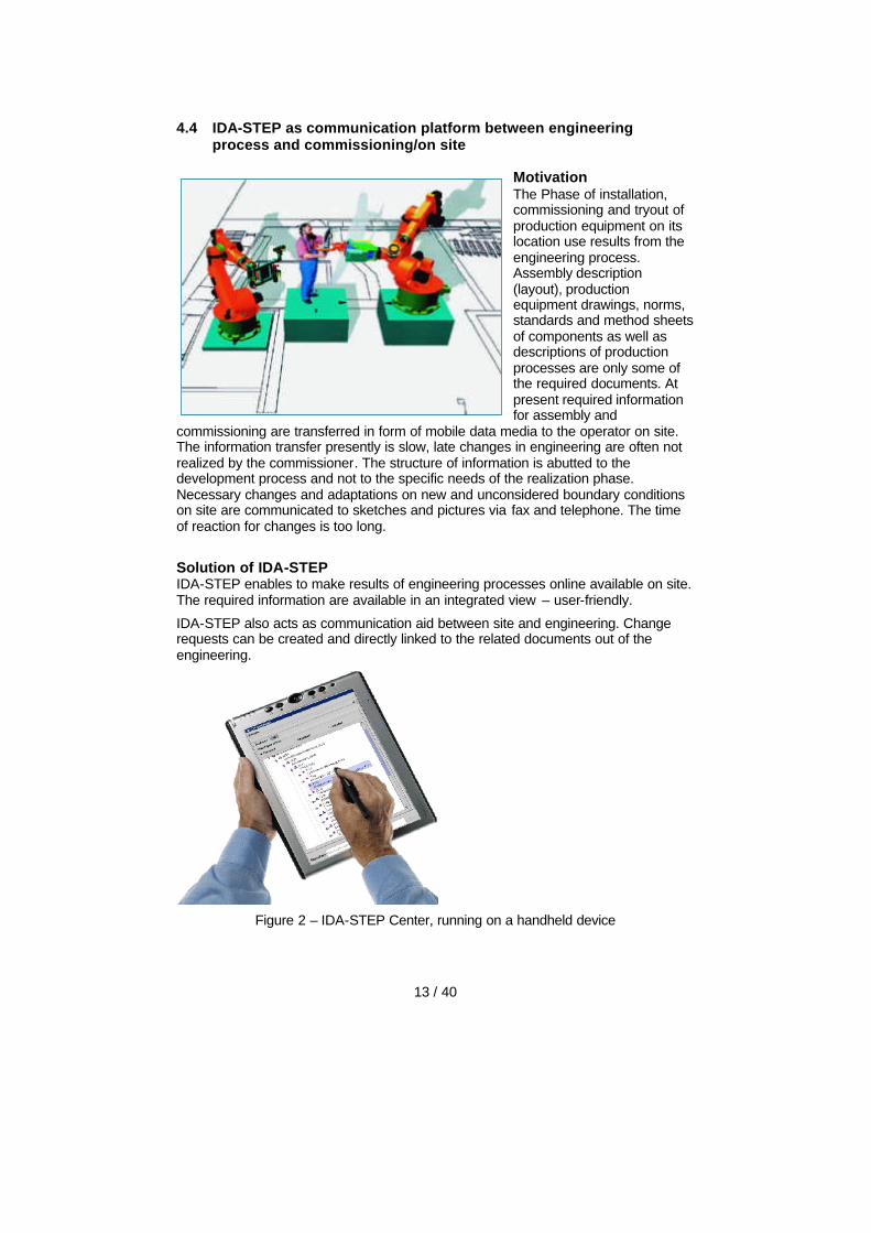
Motivation The Phase of installation, commissioning and tryout of production equipment on its location use results from the engineering process. Assembly description (layout), production equipment drawings, norms, standards and method sheets of components as well as descriptions of production processes are only some of the required documents. At present required information for assembly and
commissioning are transferred in form of mobile data media to the operator on site. The information transfer presently is slow, late changes in engineering are often not realized by the commissioner. The structure of information is abutted to the development process and not to the specific needs of the realization phase. Necessary changes and adaptations on new and unconsidered boundary conditions on site are communicated to sketches and pictures via fax and telephone. The time of reaction for changes is too long.
Solution of IDA-STEP IDA-STEP enables to make results of engineering processes online available on site. The required information are available in an integrated view – user-friendly.
IDA-STEP also acts as communication aid between site and engineering. Change requests can be created and directly linked to the related documents out of the engineering.
Figure 2 – IDA-STEP Center, running on a handheld device
14 / 40
4.5 IDA-STEP for the integration of of mechanical and electrical data
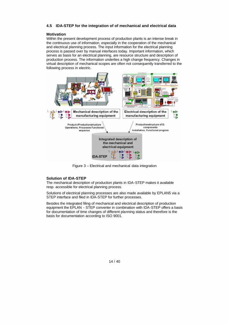
Motivation Within the present development process of production plants is an intense break in the continuous use of information, especially in the cooperation of the mechanical and electrical planning process. The input information for the electrical planning process is passed over by manual interfaces today. Important information, which serves as basis for an electrical planning, are resource structure and description of production process. The information underlies a high change frequency. Changes in virtual description of mechanical scopes are often not consequently transferred to the following process in electric.
Figure 3 – Electrical and mechanical data integration
Solution of IDA-STEP The mechanical description of production plants in IDA-STEP makes it available resp. accessible for electrical planning process.
Solutions of electrical planning processes are also made available by EPLAN5 via a STEP interface and filed in IDA-STEP for further processes.
Besides the integrated filing of mechanical and electrical description of production equipment the EPLAN - STEP converter in combination with IDA-STEP offers a basis for documentation of time changes of different planning status and therefore is the basis for documentation according to ISO 9001.
15 / 40
4.6 IDA-STEP as basis for system neutral long- time archiving
Motivation In the aerospace and military industry the required retention period is oriented on maturity of product lifetime. Today periods of 40 years and longer are required. Usual retention periods in automotive industry for project and product dependent documents are 5 to 30 years.
Filing and storage of documents has to be done so that they contain the required information for argumentation:
• Adherence of contracts
• Adherence of legal/official documents
• Traceability of documents
• Modification of products and documents, mainly for product liability and guaranty cases
The STEP- standard offers the ideal filing format for product data in many industrial branches, especially in automotive, electrical and electronics. STEP worldwide is an approved standard, which is applicative for filing of complex product descriptions.
Solution of IDA-STEP IDA-STEP offers a special possibility for data preparation for long-term storage and for viewing of filed data later on. IDA-STEP ensures full conformity with the STEP standard. This guarantees readability of data also after decades.
A basic point is the platform neutral visualization of STEP- data. This especially includes assembly structure, referenced documents as well as STEP geometry descriptions in 2D and 3D.
STEP- data, which result from CAx- systems are often incomplete and/or faulty. E.g. responsibilities and releases are often faulty defined (Mr. Mustermann, John Doe, etc.). IDA-STEP offers a simple and clear possibility to correct and fulfill those data.
Java as basis for IDA-STEP
Besides long-term storage of data it is also necessary to provide with software application for future viewing and inspection of the data.
Software applications programmed in C or C++ require computer architecture, which support the so-called pointer arithmetic (e. g. ++- operator). This is given for the most common computer architectures, however it is problematic whether it is given in future or not. For a while computer architectures exist which address and data bus are divided and partly not supported by pointer arithmetic.
Also some C/C++- applications are developed for 32 bit processors and do not necessarily work in a 64 bit environment as many programs come from the presumption, that a pointer has a length of 32 bit. It has to be considered that a 32 bit architecture has a physical limit of addressable storage. Complex applications are limited already today.
The platform neutral Java Virtual Machine (JVM) can work on all powerful computer systems today and because of its clean design is adoptable to all future computer platforms. It can be assumed that the selected Java technology for IDA-STEP obtains the necessary long-term stability to be used in future (> 30 years). Therefore, IDA-STEP offers an ideal platform for long-term storage – not only for data but also for application.
16 / 40
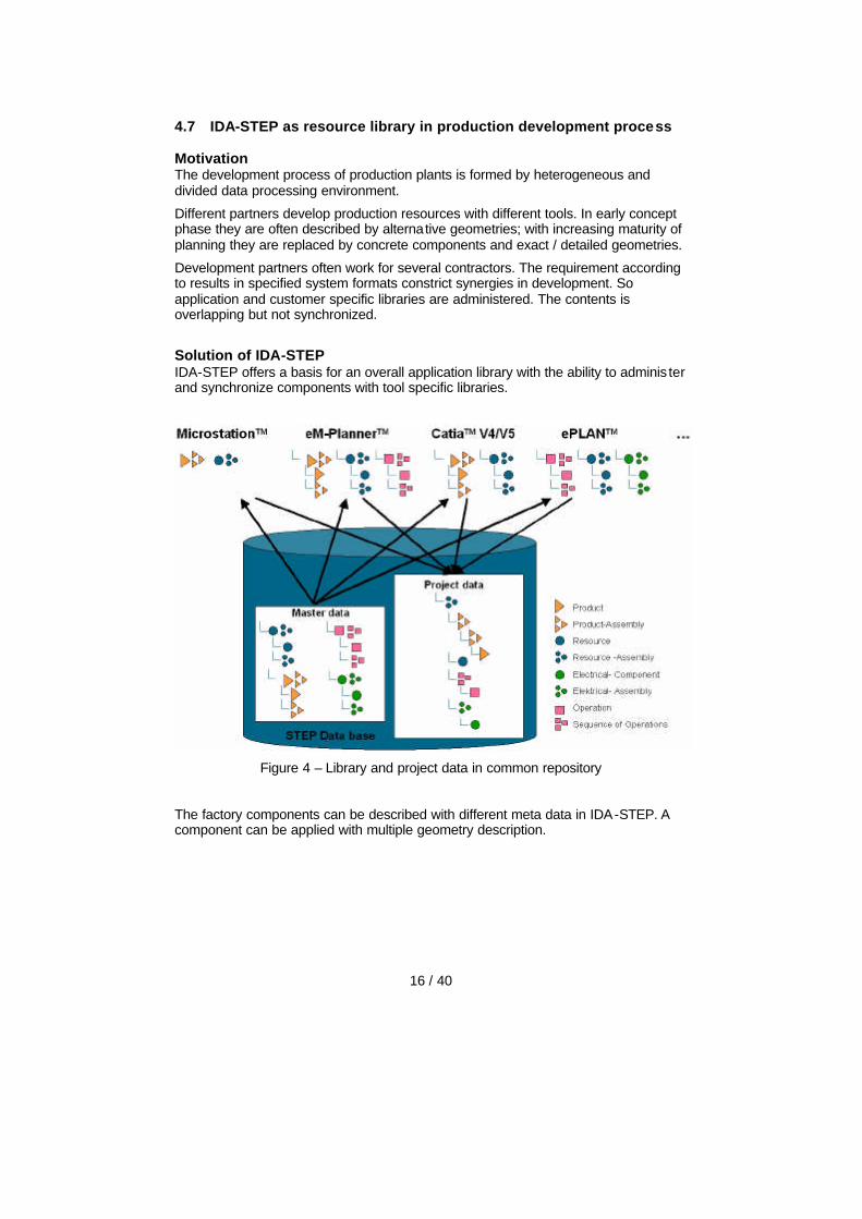
4.7 IDA-STEP as resource library in production development process
Motivation The development process of production plants is formed by heterogeneous and divided data processing environment.
Different partners develop production resources with different tools. In early concept phase they are often described by alternative geometries; with increasing maturity of planning they are replaced by concrete components and exact / detailed geometries.
Development partners often work for several contractors. The requirement according to results in specified system formats constrict synergies in development. So application and customer specific libraries are administered. The contents is overlapping but not synchronized.
Solution of IDA-STEP IDA-STEP offers a basis for an overall application library with the ability to adminis ter and synchronize components with tool specific libraries.
Figure 4 – Library and project data in common repository
The factory components can be described with different meta data in IDA-STEP. A component can be applied with multiple geometry description.
17 / 40
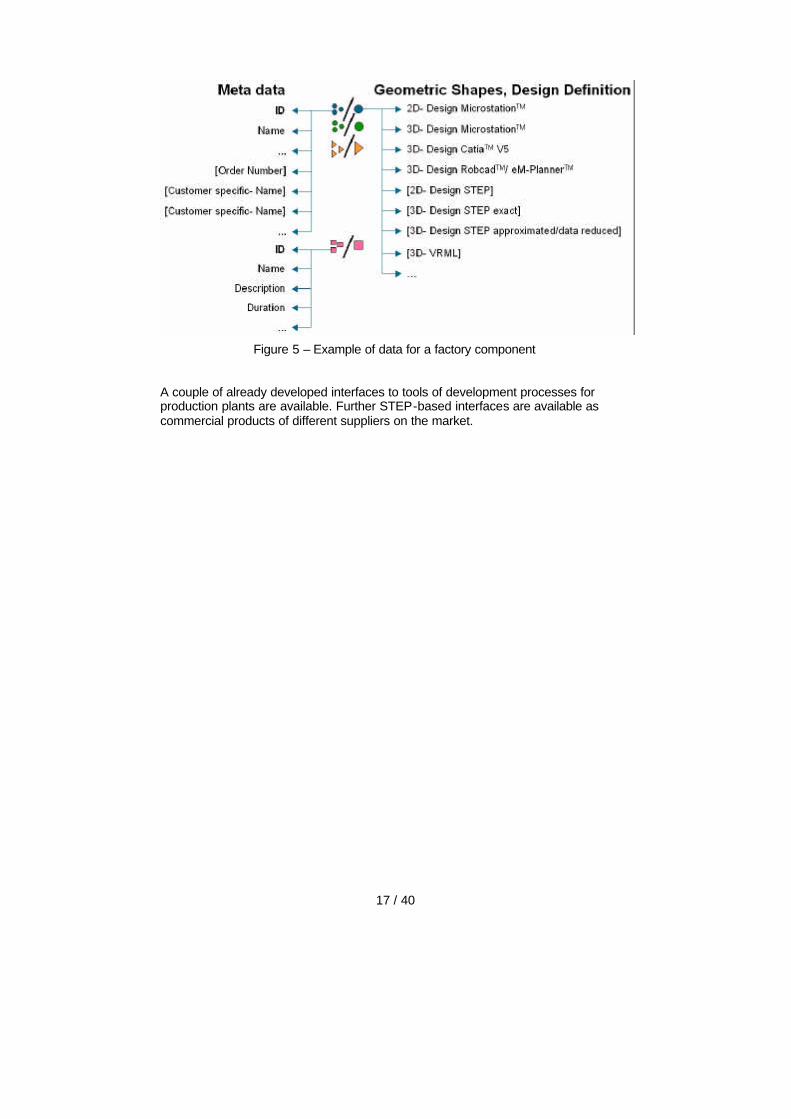
Figure 5 – Example of data for a factory component
A couple of already developed interfaces to tools of development processes for production plants are available. Further STEP-based interfaces are available as commercial products of different suppliers on the market.

18 / 40
5 Major Technical Results
The picture below gives an overview of the software and other components developed and extended during the project time.
Figure 6 – Major deliverables of the IDA-STEP project
The STEP toolkit JSDAI is the backbone for all the software development throughout the IDA-STEP project. A STEP-database using Oracle or MySQL is realized by linking JSDAI via the JSDAI SQL Bridge with a relational database
A STEP based Digital Factory is realized in this database by accumulating data from various sources such as 2D and 3D geometry, physical assembly structures, process plan, electrical installation, and feedback information from the installat ion and tryout phase.
Geometric information is generated various CAD systems (CATIA v4, CATIA v5, UG, MicroStation) and can be imported using traditional STEP-Files. The source of the physical assembly structure and process plan information are PDM/EDM systems and process planning tools. Complying interfaces were developed within the project timeframe.
5.1 JSDAI
JSDAITM is a full features implementation of the STandard Data Access Interface (SDAI) for the Java programming language. JSDAI is a kind of Application Programming Interface (API), which fully conforms to STEP (ISO 10303-11, -21, -22, -27, and -35).

19 / 40
Figure 7 – Kernel structure of JSDAI
As part of the IDA-STEP development the JSDAI toolkit was improved and extended in several major areas:
• A generic XML import / export facility with adoptions of
o ISO 10303-28, edition 1, Late Binding, DTD based
o ISO 10303-28, edition 2, XML-Schema binding
• Implementation of Express-X (ISO 10303-28) with full Express expression evaluation
• Completely reworked database implementation with SDAI transactions directly mapped to the database transactions. By this a true multi-user SDAI repository got realized.
• A new universal XML query language for EXPRESS, suitable for local and remote repositories.
• STEP Applications Protocols are characterized by providing two distinct data models, the Application Reference Model (ARM) and the Application Integrated Model (AIM). The ARM -AIM mapping extension of JSDAI was greatly extended, allowing automatic translations between both models. This is the basis for efficient implementation of converters and user interfaces.
• 3D viewing (see below)
See www.jsdai.net for detailed information.

20 / 40
5.1.1 3D Viewing
A primary goal of the IDA-STEP project is to visualize STEP geometry on handheld devises. For this it was important to have a platform neutral solution and not to focus on devices using Microsoft windows. The Java3DTM API, an extension to the JavaTM 2 platform was considered as the right way to go, together with JSDAI. Since no other 3D viewer for Java was available the IDA-STEP consortium developed a new one, using the experiences of an early prototype, which was developed before the project.
The 3D Viewing capability is realized as a reusable software component on top of JSDAI. It can not only be used within the IDA-STEP application but also for other applications as well.
5.1.2 STEP 3D Geometry
Based on the generic STEP geometry as defined in part 42 several specialized geometric representations are defined in STEP as Application Interpreted Constructs (AIC) and interfaced into AP214. The most important geometry representation used today are the topological bounded Advanced Boundary Representation (A-BREP, AIC 514) and Manifold Surface (AIC 509). Simpler geometric representations such as 3D-Wireframe (AIC 501 and 502), or Facetted Breps (AIC 512) plays only a little role. Constructive Solid Geometry (CSG, AIC 515) is not yet in use today.
Figure 8 – Frame rail of car
STEP geometry data can be mapped into Java3D API. For this the elementary and parametric defined surfaces and their boundaries needs to be transformed into a tessellated form. This triangulation process is typically a core part of any 3D CAD system. As part of the IDA-STEP project the first triangulation algorithm specialized for STEP geometry and completely written in Java was developed. This algorithm is

21 / 40
able to process all STEP geometric models defined in AICs with the exception of CSG.
The resulting Java 3D "scene graph" out of the triangulation process is displayed in a Java 3D pane. Additional controls are added to zoom, move, rotate, defined clipping panes, hide components or make them transparent etc.
The JSDAI 3D-Viewer was developed as a generic software module, which can be used in various applications. One major use is within the IDA-STEP application. Here it is important that the viewer smoothly interact with a hierarchal assembly tree. This was fully developed, including selecting and highlighting of components in both directions. Please find in the next clause on Kinematics another usage of the generic software module.
The JSDAI 3D-Viewer was tested with many examples from the CAX-IF implementation group (www.cax-if.org) including production models. Further examples come from EDAG, ASM and FFT using CATIA (v4 and 5) and UG.
5.1.3 VRML support
To be able to view STEP Geometry on very thin clients with no Java3D available the alternative neutral solution is in using the VRML standard.
There are two ways to generate and mange the needed VRML files; either by optimized translators available for various M-CAD systems or by a generic solution to generate the VRML files directly out of the neutral STEP geometry. Both alternatives got realized within IDA-STEP. Externally generated VRML files can be managed as digital_files within IDA-STEP. If no externally generated VRML file is available a new one is generated on the fly from the JSDAI 3D viewer.
Typically one VRML file is generated for one part. To display an assembly several VRML files (one for each part) are collected together into an “VRML assembly” file with the needed transformations. This file is generated by IDA-STEP on the fly.
5.2 STEP-Book
The generic STEP-Book, running on top of JSDAI , is another used major software component. It allows to create flexible graphical user interfaces (GUI) to operate on EXPRESS defined data. This includes viewing of data in trees and info pages, modifying the data and creating new data in wizards. The generic STEP-Book is adopted to particular data models such as AP212 and 214 by providing XML configurations. A particular user interface can be modified by simply changing the XML configuration and restarting STEP-Book, without any additional compilation.
The XML-configuration does not only cover the user interface but also the underlying business logic to follow. Whenever data is created or modified it is compared with the business logic to ensure e.g. that mandatory attributes are set or that attributes ha ve unique values.
The logic of processing the XML configuration is separated from the generated user interface. This allows to use one XML-configuration to generate three different kind of user-interfaces:
• Workstation mode: Here the client part of STEP-Book is directly integrated with the server part and JSDAI to generate a heavy weight Java user interface using swing.
22 / 40
• Fat client mode: Here the STEP-Book client is separated from the server part of STEP-Book and JSDAI via an Internet connection. The client is operating as a thick applet; e.g. in a web browser
• Lightweight client mode: Here the user interface is directly mapped into HTML pages using Java servelet technology. The result can be viewed by every web-browser.
See www.jsdai.net under “STEP-Book” for more detailed information.
5.3 IDA-STEP schema (AP214+AP212+AIM)
As part of the IDA-STEP project a new Express schema was developed to solve several implementation problems. The IDA-STEP schema is not a complete new schema – it is a schema to merge things together, which are already defined in STEP AP212 and AP214 on ARM and on AIM level in a new way.
Reasons why to have the IDA-STEP schema
STEP AP212 and AP214 are distinct standards, which are not formally merged or mapped to each other. However the original motivation when they were developed was that it should be possible to use them together. The main overlapping area of AP212 and AP214 is on physical and connectional assembly structure, classifications, and properties.
STEP provides for this usage a general-purpose solution, given by the integrated resources to which all STEP APs are mapped (AIM). This common use on the AIM level is also supported by SDAI (part-22) and the 2nd edition of STEP-File (part-21). In practice however there are a couple of problems in doing so:
• The AIM schemas of AP214 and AP212 are very similar and have a big overlap, and also the ARM schema of AP214 and AP212 have lots of common or similar entities. But when looking in more detail to this we can identify some 150 differences on the ARM level! The main reason for this is , that the development of these standards got harmonized on the CD and DIS stage, but not for the final IS stage. Details of the AP214-212 harmonization problems are given in project deliverable D13c-v2.pdf – on request.
• Also there is no common Express schema in which we can held the common entity instance such as product, product_definition_formation, product_related_ product_category, etc.. Originally we intend to use the low level schemas from the STEP integrated resources for this purpose, but this will make problems with the STEP xxx_assignment entities, e.g. for the id_owner, approval, etc. (see also extensible selects in Express v2 as the recommended solution).
• It is possible to directly operate on AIM data for viewing and editing purpose. LKSoft has developed powerful tools to do so, allowing to virtually work with ARM concepts on AIM data. However this lead to some performance problems and further analysis shows that it is much more efficient to operate primarily on the ARM level and do the needed conversions only when import/export activities to other tools or for data exchange are needed.
• Another problem is with the STEP implementation methods, which do not allow populating data-sections (resp. SdaiModel) with instances following more than one schema. LKSoft made the proposal to extend the STEP parts 21/22/28 in such a way that when listing more than schema a new virtual schema is defined, interfacing (USE FROM) all the listed schemas. This

23 / 40
proposal did not find a majority in ISO TC184/SC4-WG11 and so the current STEP strategy is still to have a master schema, including both partial schemas. Because such a schema is not standardized it could not be used for neutral data exchange. However an implementation may use it inside.
• For this LKSoft investigated the possibility to merge AP212 and 214 on ARM level by defining a core 212-214 schema and then having AP212 and AP214 specific extensions. E.g. the core schema would include all entities for product identificat ion and assembly. The AP214 extension would then contain all the geometry, kinematic, features and tolerance entities. The AP212 extension would contain all entities for electrical connectivity and GIS placement. While doing so we figured out many incompat ibilities on the ARM level as documented in D13c-v2.
• With the new modular approach within ISO TC184/SC4 is would be possible to solve this problem. Both AP212 and AP214 would have to be divided into modules and then collected into modular APs. Having both APs on a modular level it would be possible to make a super-module combining AP212 and 214. In theory this would be easy to do. In practice however this is much more complicated. Till today there are no activities in making modular APs out of AP212 and 214.
Because of all these problems we choose a different strategy within the IDA-STEP project by going for a unified IDA-STEP schema.
Strategy in building up the IDA-STEP schema
The IDA-STEP schema is mainly an ARM based schema, covering complete AP214 and major parts of AP212. The development of the schema starts by copying the complete AP214 ARM. Then all geometric entities were replaced by corresponding AIM entities. The same happens with entities on units and in a few other areas. So the IDA-STEP schema is identical to AP214 AIM in the geometry and unit area, and also identical to AP214 ARM in all other areas.
Next the IDA-STEP schema was extended by AP212 specific functionality. While doing this we assumed that AP214-ARM and mapping had priority over similar concepts in AP212. From AP212 the physical connectivity structure was added into the IDA-STEP schema, mainly interface_terminals, terminals and connections. Further on AP212 specific designations (terminal_designation, object_designation, document_designation) were added, because AP214 does not support this kind of functionality. Also some AP214 select types are extended in IDA-STEP schema to support AP212, e.g. item, item_version, drawing_sheet can have property assigned.
Effectively the IDA-STEP schema is a merging of AP214 and AP212 ARM schemas with extensions to make it directly implementable.
The IDA-STEP schema is not intended to become in any way a part of the STEP standard. Its only purpose is to be a native implementation schema to/from which STEP Data can easily be imported/exported.
With updating and extending the AP214 mapping by the specific AP212 entities and also updating the CxClasses in JSDAI it is now possible to
• import and export of AP203 STEP files (AIM) • import and export of AP212 STEP files (AIM) • import and export of AP214 STEP files (AIM), compatible with the PDM
schema (a schema widely used within STEP but is not a standard) • import and export of PDTnet files (AP214 ARM)
24 / 40
5.4 IDA-STEP Center and IDA-STEP Viewer
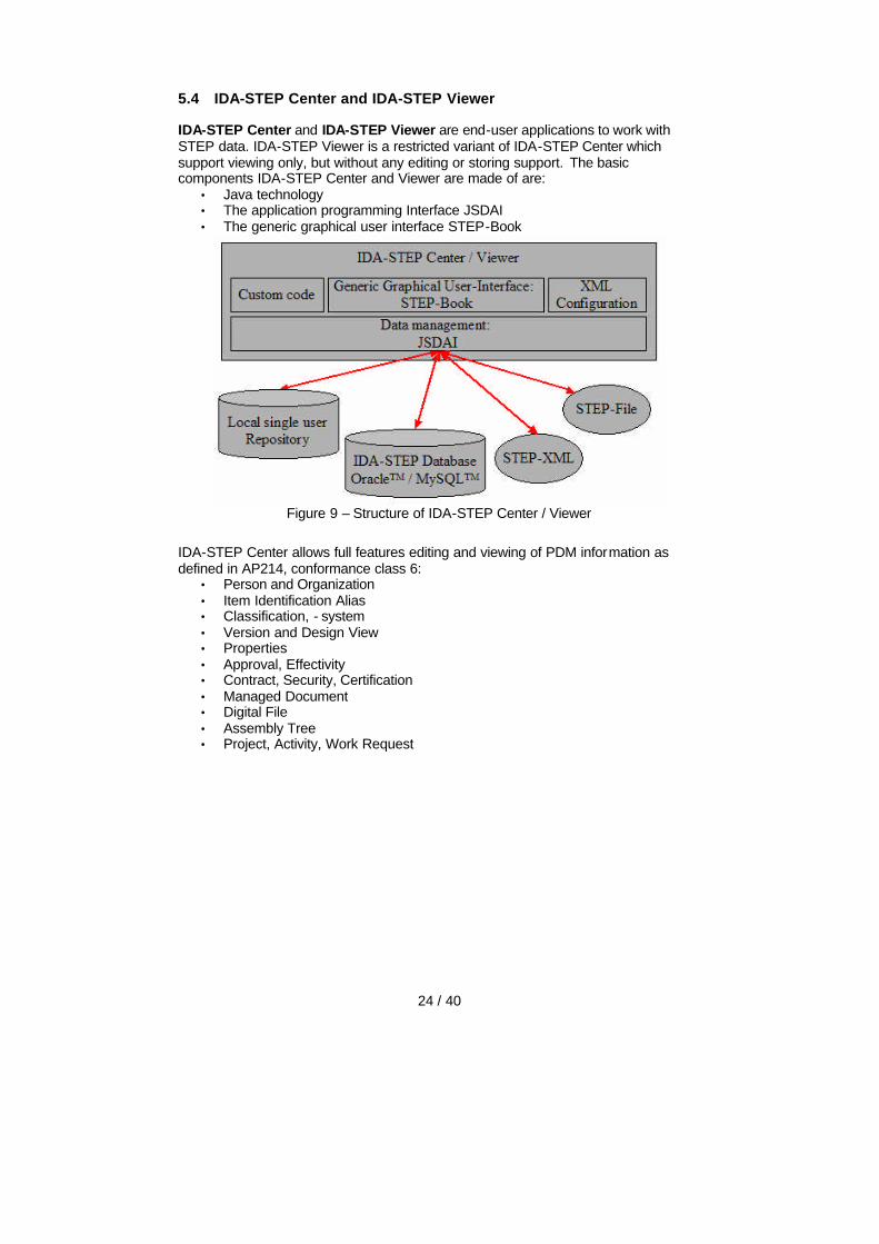
IDA-STEP Center and IDA-STEP Viewer are end-user applications to work with STEP data. IDA-STEP Viewer is a restricted variant of IDA-STEP Center which support viewing only, but without any editing or storing support. The basic components IDA-STEP Center and Viewer are made of are:
• Java technology • The application programming Interface JSDAI • The generic graphical user interface STEP-Book
Figure 9 – Structure of IDA-STEP Center / Viewer
IDA-STEP Center allows full features editing and viewing of PDM information as defined in AP214, conformance class 6:
• Person and Organization • Item Identification Alias • Classification, - system • Version and Design View • Properties • Approval, Effectivity • Contract, Security, Certification • Managed Document • Digital File • Assembly Tree • Project, Activity, Work Request

25 / 40
In addition various kinds of geometry can be displayed:
• Visualization of 3D STEP-geometry models • Visualization of 2D STEP-drawings and -geometry models • Generation of VRML of single parts and assemblies • Linking of 2D-geometry models with components of an assembly structure
Process Plan (viewing only)
• Hierarchy of process operations • Parts going in and out • Used resources • Operation properties such as cycle time
Data Exchange and Integration
• Import and export of STEP AP203, 212 and 214 files • Interactive merging via Copy & Paste • Data integration in a remote STEP database • Automatic merging with versioning
Electric STEP-AP212 (viewing only)
• Technical Drawings • Assembly structure with properties, classif ication etc. • Terminals and connection (IDA-STEP v1.0)

26 / 40
5.5 Kinematic
Applying the kinematic model as defined in STEP AP214 and STEP IR105 (including TC1 and TC2) for real industrial use cases was another challenging tasks within the IDA-STEP project. For this we searched for further documentation because the standard itself gives no guidance or examples on how to use kinematic.
• ATS 314, test case 6.22 is on Kinematics. However this test case is in no way complete or consistent.
• The AP214 validation report mention working groups within the German VDA and ProSTEP association, but these groups are no longer active and there are no results available from them. The validation report itself does not contain a kinematic example
• All the known STEP usage guides do not contain any guidance on kinematics
• Alternative kinematic studies such as the InterRob project and Mechatronic specify datamodels, but do not give examples or explain on how to use them.
• The only real example we found is listed in "Interoperability of Standards for Robotics in CIME". However the example is based on very early draft models of the standard and are incomplete (no product structure).
• STEP IR-109/CD "Kinematic and geometric constraints for assembly models" has in scope: "The representation of detailed geometric information of instanced assembly feature relationship in geometric_representation_item level such as assembly geometric constraints, kinematics pair and kinematics path; " This new part of STEP was not considered for the IDA-STEP project, because it is not part of AP214, there are no plans to include it in AP214 and its main focus is on the detailed kinematic movement and its constraints for the assembly process. This is beyond the scope of IDA-STEP, but maybe addressed in a follow up project.
During the project several deficits of the standards were detected. A main flaw in AP214 is that there is no way to unambiguously relate the components (single_instance) of an assembly structure to kinematic links (to be fixed in the next release)
Nevertheless the consortium was able implement an early prototype of a kinematic editor. Input to this is a STEP assembly structure with geometry form some M -CAD system. The assembly structure is then converted into a kinematic structure. This is done by creating kinematic-link objects for the individual moving parts and defining one or several placements for them (see picture). In the next step these placements are taken to create pairs of kinematic links of pair-type revolute, cylindrical, prismatic etc. Depending of the pair type the placements define how the kinematic links can move relative to each other. In a next step range values for each kinematic pair can be defined, specifying minimal and maximal values. In e.g. one can say that the position of a door can be between 0 and 90 degree, but it can’t be negative or greater than 90 degree. Finally a static kinematic configuration can be specified by providing values for each pair. A kinematic movement is given as an interpolation between two kinematic configurations.
The resulting STEP kinematic structure can finally be transformed into VRML to be viewed in a web browser. Alternatively it can be displayed in an extended JSDAI 3D viewer. An example STEP-file with kinematics is available at www.ida-step.net

27 / 40
Figure 10 – Kinematic link with assigned placement
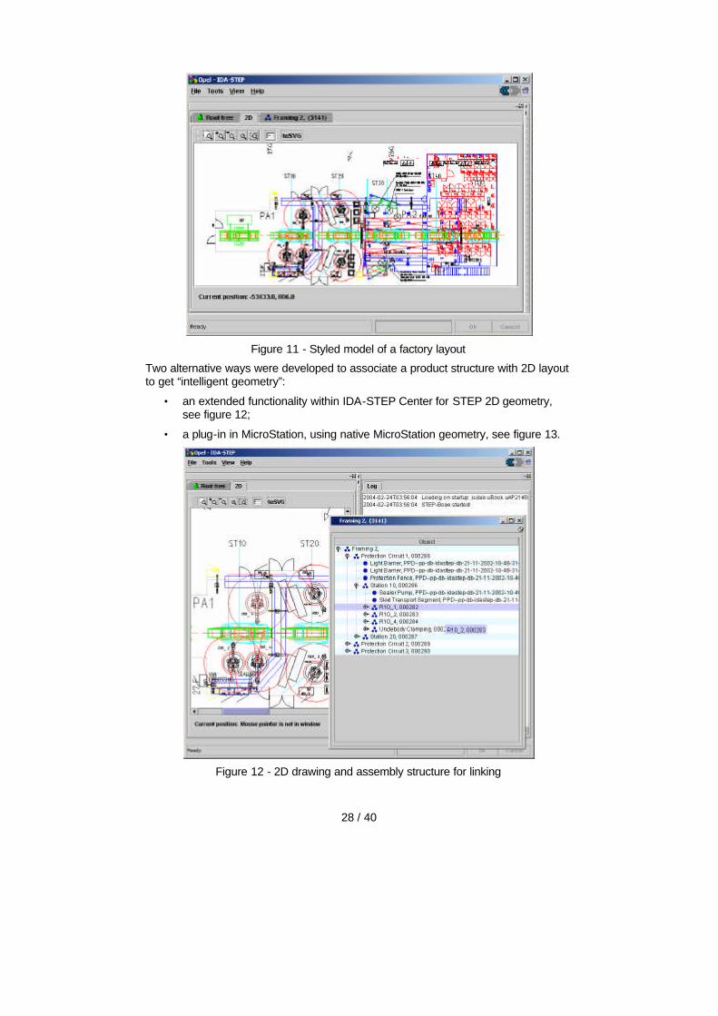
5.6 2D Layout and technical Drawing
STEP support 2D geometry in three related ways:
• as 2D-wireframe model, as a direct representation of the object
• as styled model, using the 2D-wireframe or parts of it and associating colors, layers, line width, and text etc.
• as schematic diagram, consisting of one or several pages with a frame, header box etc.
IDA-STEP Center/Viewer is supporting all these geometries. Via a DXF or MicroStation converter such data can be imported into IDA-STEP Center.
However all these converters produce only bare 2D geometry without any related product structure. But this structure is typically available in a PDM or process planning system.
28 / 40
Figure 11 - Styled model of a factory layout
Two alternative ways were developed to associate a product structure with 2D layout to get “intelligent geometry”:
• an extended functionality within IDA-STEP Center for STEP 2D geometry, see figure 12;
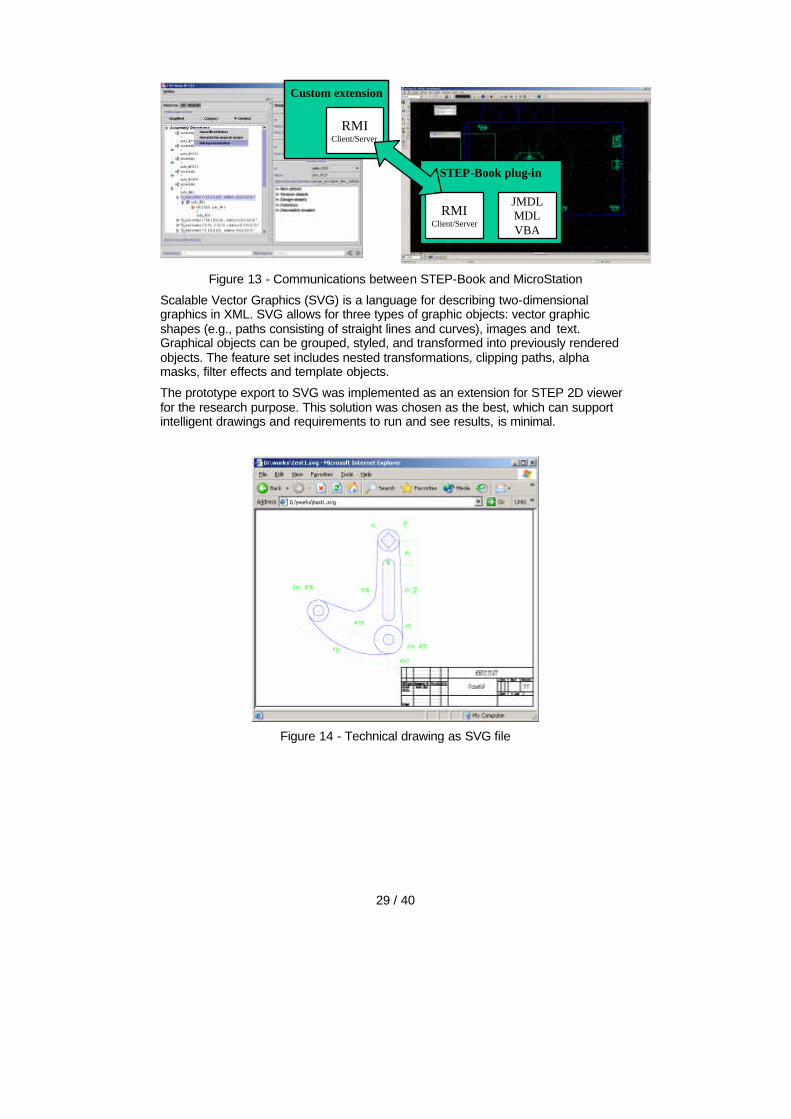
• a plug-in in MicroStation, using native MicroStation geometry, see figure 13.
Figure 12 - 2D drawing and assembly structure for linking
29 / 40
STEP-Book plug-in
RMIClient/Server
JMDLMDLVBA
STEP-Book plug-in
RMIClient/Server
JMDLMDLVBA
Custom extension
RMIClient/Server
Custom extension
RMIClient/Server
Figure 13 - Communications between STEP-Book and MicroStation
Scalable Vector Graphics (SVG) is a language for describing two-dimensional graphics in XML. SVG allows for three types of graphic objects: vector graphic shapes (e.g., paths consisting of straight lines and curves), images and text. Graphical objects can be grouped, styled, and transformed into previously rendered objects. The feature set includes nested transformations, clipping paths, alpha masks, filter effects and template objects.
The prototype export to SVG was implemented as an extension for STEP 2D viewer for the research purpose. This solution was chosen as the best, which can support intelligent drawings and requirements to run and see results, is minimal.
Figure 14 - Technical drawing as SVG file
30 / 40
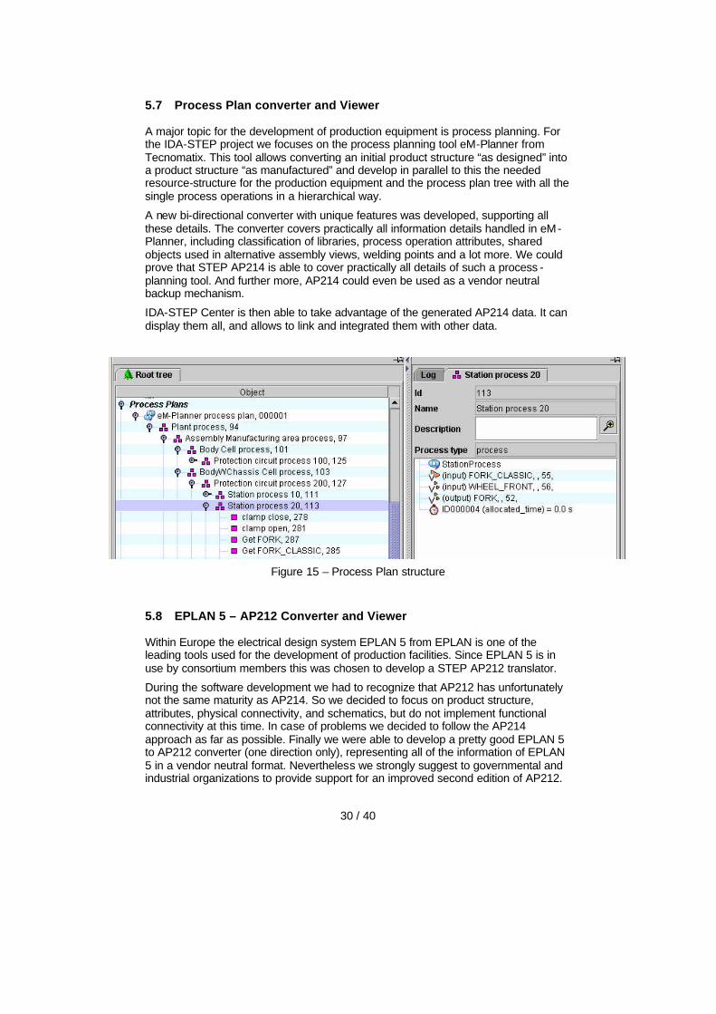
5.7 Process Plan converter and Viewer
A major topic for the development of production equipment is process planning. For the IDA-STEP project we focuses on the process planning tool eM-Planner from Tecnomatix. This tool allows converting an initial product structure “as designed” into a product structure “as manufactured” and develop in parallel to this the needed resource-structure for the production equipment and the process plan tree with all the single process operations in a hierarchical way.
A new bi-directional converter with unique features was developed, supporting all these details. The converter covers practically all information details handled in eM-Planner, including classification of libraries, process operation attributes, shared objects used in alternative assembly views, welding points and a lot more. We could prove that STEP AP214 is able to cover practically all details of such a process -planning tool. And further more, AP214 could even be used as a vendor neutral backup mechanism.
IDA-STEP Center is then able to take advantage of the generated AP214 data. It can display them all, and allows to link and integrated them with other data.
Figure 15 – Process Plan structure
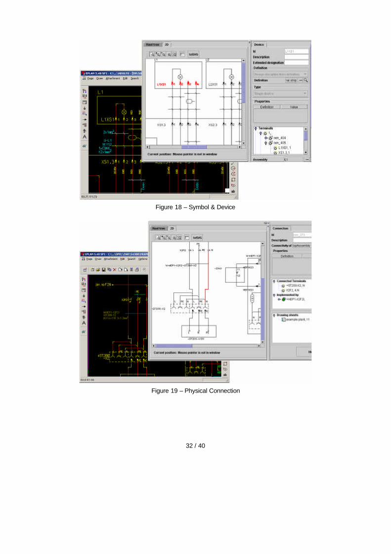
5.8 EPLAN 5 – AP212 Converter and Viewer
Within Europe the electrical design system EPLAN 5 from EPLAN is one of the leading tools used for the development of production facilities. Since EPLAN 5 is in use by consortium members this was chosen to develop a STEP AP212 translator.
During the software development we had to recognize that AP212 has unfortunately not the same maturity as AP214. So we decided to focus on product structure, attributes, physical connectivity, and schematics, but do not implement functional connectivity at this time. In case of problems we decided to follow the AP214 approach as far as possible. Finally we were able to develop a pretty good EPLAN 5 to AP212 converter (one direction only), representing all of the information of EPLAN 5 in a vendor neutral format. Nevertheless we strongly suggest to governmental and industrial organizations to provide support for an improved second edition of AP212.

31 / 40
Figure 16 to 19 shows several details of original information in EPLAN 5 and how it looks when it is converted into neutral STEP AP212 data and displayed in IDA-STEP.
Figure 16 – Assembly hierarchy, the devices G1, G2, … are included in device SV
Figure 17 – Connection & Cable assignment
32 / 40
Figure 18 – Symbol & Device
Figure 19 – Physical Connection
33 / 40
5.9 STEP – PDM Integration
Linking STEP data with the one in a Product Data Management (PDM) system was another major focus of the IDA-STEP project. For this we developed a bi-directional translator for eMatrix. This converter supports product structure and the structure of the production facilities as well as various properties. During export a particular configuration (product variant) can be chosen. During import data is merged with the data already included in the PDM system. This includes automatic versioning and control of access rights. The converter supports AP214 CC 6.
Afterwards a similar bi-directional STEP converter for the PDM system Teamcenter Engineering was developed. These tools were primarily developed for the internal usage within EDAG but are designed in such a way that external customers can also use them.
Meanwhile both converters are in productive use within EDAG. There are significant time and money savings in the daily data exchange with OEMs. Further OEMs and sub-suppliers to be integrated in the near future.
5.10 Data merging
IDA-STEP provides two strategies on how to merge two or more STEP data sets together, interactive and automatic merging. Interactive merging is mainly based on including one data set into the other and then editing the objects and relations with delete, copy and paste to the final result. Interactive merging is most flexible, but it can be a tedious work for big datasets and repetitive tasks.
Automatic merging can be split into the basic tasks
• data comparison,
• decision taking on the actions to perform
• action execution
All three tasks depends very much on the kind of data to merge together, on the data sources, and on the actual business cases. Consequently there is not a single way how to do merge but there are many options how to do things.
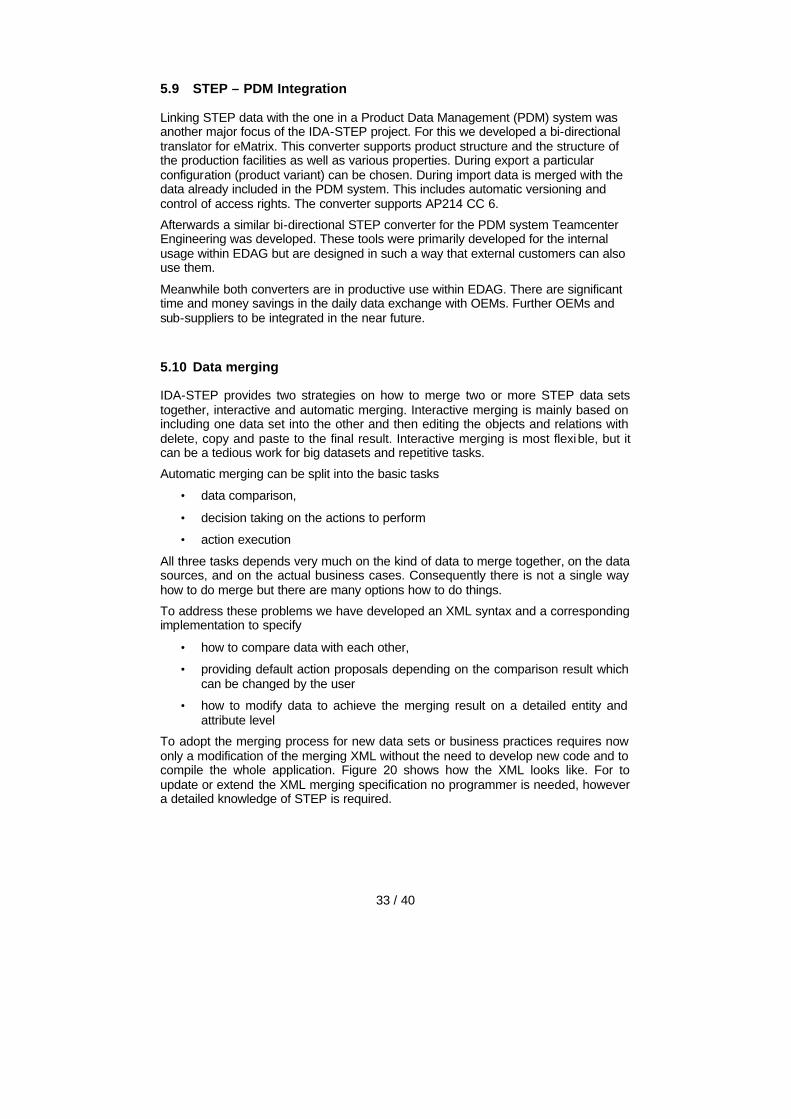
To address these problems we have developed an XML syntax and a corresponding implementation to specify
• how to compare data with each other,
• providing default action proposals depending on the comparison result which can be changed by the user
• how to modify data to achieve the merging result on a detailed entity and attribute level
To adopt the merging process for new data sets or business practices requires now only a modification of the merging XML without the need to develop new code and to compile the whole application. Figure 20 shows how the XML looks like. For to update or extend the XML merging specification no programmer is needed, however a detailed knowledge of STEP is required.
34 / 40
Figure 20 - Usage of Java class methods to perform diff tasks
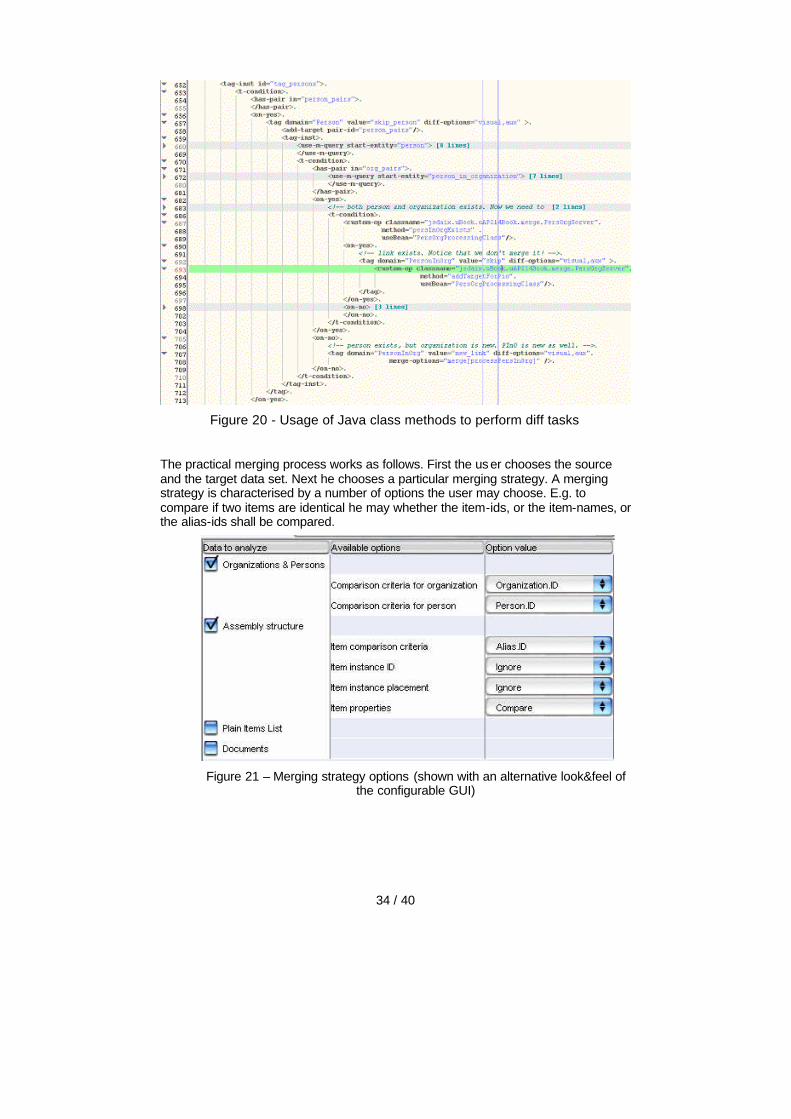
The practical merging process works as follows. First the us er chooses the source and the target data set. Next he chooses a particular merging strategy. A merging strategy is characterised by a number of options the user may choose. E.g. to compare if two items are identical he may whether the item-ids, or the item-names, or the alias-ids shall be compared.
Figure 21 – Merging strategy options (shown with an alternative look&feel of
the configurable GUI)
35 / 40
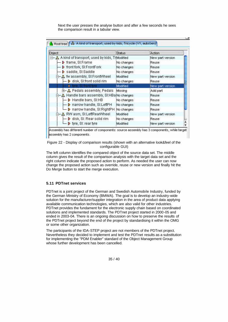
Next the user presses the analyse button and after a few seconds he sees the comparison result in a tabular view.
Figure 22 - Display of comparison results (shown with an alternative look&feel of the
configurable GUI)
The left column identifies the compared object of the source data set. The middle column gives the result of the comparison analysis with the target data set and the right column indicate the proposed action to perform. As needed the user can now change the proposed action such as override, reuse or new version and finally hit the Do Merge button to start the merge execution.
5.11 PDTnet services
PDTnet is a joint project of the German and Swedish Automobile Industry, funded by the German Ministry of Economy (BMWA). The goal is to develop an industry-wide solution for the manufacturer/supplier integration in the area of product data applying available communication technologies, which are also valid for other industries. PDTnet provides the fundament for the electronic supply chain based on coordinated solutions and implemented standards. The PDTnet project started in 2000-05 and ended in 2003-04. There is an ongoing discussion on how to preserve the results of the PDTnet project beyond the end of the project by standardising it within the OMG or some other organization.
The participants of the IDA-STEP project are not members of the PDTnet project. Nevertheless they decided to implement and test the PDTnet results as a substitution for implementing the "PDM Enabler" standard of the Object Management Group whose further development has been cancelled.

36 / 40
The focus of PDTnet is to establish a link between product data technology and communication technology. One of the goals is the translation of a product data storage format in a form suitable for exchange by different product data management (PDM) systems. PDTnet defines an XML Schema for neutral product data communication. The PDTnet schema is equivalent to a subset of the AP214 ARM schema, close to conformance class 6 of AP214 (PDM with external geometry). It is the intension to extend PDTnet in future so that it covers all of the non-geometric entities.
PDTnet uses the EXPRESS XML representation of ISO 10303-28, 2nd edition. The implementation of the PDTnet schema results in a PDTnet service (server), which is responsible for processing of client queries and serving appropriate results and a corresponding PDTnet client. The majority of queries correspond to requests of certain product data.
Within the IDA-STEP project a prototype implementation of a PDTnet service got developed, using JSDAI and the STEP database.
6 Test Scenarios
The developed software was tested by the industrial partners with data from seve ral examples:
• Several production stations for the body-in-white framing line of the Opel Meriva factory in Zaragoza, Spain (EDAG and FFT)
• “Glass Spider” application to assemble windshields to the car (ASM)
• Airbus “wing turner“ (ASM)
• Demo factory for body-in-white frame rail production at EDAG / Fulda. (EDAG)
During these activities data from different sources were collected and integrated. Partly this data had even to be created within IDA-STEP:
• Product structure as designed and as manufactured
• Process plan and resource structure
• Factory Layout in 2D
• Mechanical 3D design of product and production equipment
• Electrical installation
• Change requests from onsite installation and tryout phase

37 / 40
Figure 23 - Merging process on demo factory during final event:
Figure 24 - Clamping unit with frame rail, IDA-STEP plugin for CATIA v4
38 / 40
7 Lessons Learned
All the goals and activities of the IDA-STEP project can be grouped in two parts:
• First, integrating of all the relevant data sources for the design on the basis of STEP and
• Second making this information available for end-users on the factory side for the installation and try-out phase.
The first part was expected to be almost done till half time of the project timeframe. In fact this was also the case, but then because of various changes on the CAD/PDM tool side and other problems this phase was extended till the end of the project. Consequently the second part of the project felt short and could not addressed in the depth as needed. Looking back it may have been better to have two separate projects, one for each part, and have started the second project only when the first got finished.
The scientific and technological goals of the project were very high – a little bit too high for the available resources. Fortunately the IDA-STEP consortium was rather small, so it could work much more efficient than a bigger consortium would have been able.
The project benefits strongly by the excellent support and advises of the project officers and reviewers of the European Commission. This was an important factor to lead the project to success.
8 Outlook and Commercialization
One of the main goals of the IDA-STEP project was to develop software prototypes. Most of these prototypes were further developed and extended to commercial applications afterwards. This is an ongoing activity while writing this report. As of today the following commercial having their roots in the IDA-STEP project are already available or will become available soon.
• IDA-STEP Center and the free IDA-STEP Viewer
• IDA-STEP Database
• IDA-STEP converters o Tecnomatix / eM-PlannerTM
o EPLAN / EPLAN-5TM
o Mentor Graphics / Logical CableTM
o UGS / TeamcenterTM Engineering
o MatrixOne / eMatrixTM
o DXF
o IDA-STEP plugins and extensions
o Dassault / CATIATM v4 plugin
o Bently / MicroStationTM plugin (prototype)
o XML PDTnet (prototype)
• JSDAITM v3.6 with the extensions XML, and database, see www.jsdai.net
39 / 40
Because of the IDA-STEP project all partners of the consortium achieved a much higher knowledge on product data exchange in general, on STEP in particular, and how to adopt it for the realization of the Digital Factory vision. This know -how is a good basis for consulting activities of all partners and for the acquisition of further industrial projects.
9 References
1. IDA-STEP web site, see http://www.ida-step.com/
2. IDA-STEP software application version 1.2 Handbook (comes with IDA-STEP evaluation installation)
3. IDA-STEP example files, see http://www.ida-step.net under Examples
4. JSDAI software development kit for STEP version 3.6.0, see http://www.jsdai.net
5. F. Mikosch (Ed.), Interoperability of Standards for Robotics in CIME, Research Reports Esprit, Springer, 1997, ISBN 3-540-61884-8
6. Specification of a STEP Based Reference Model for Exchange of Robotics Models, ESPRIT Project 6457: InterRob Interoperability of Standards for Robotics in CIME, FZKA-PFT 176, Forschungszentrum Karlsruhe/Germany
7. Rachuri, S. et. al. (2003) Object-Oriented Representation of Electro-Mechanical Assemblies Using UML, NISTR 7057, National Institute of Standards and Technology (NIST), U.S.A.
8. Klein, L. et. al. (1998) SDAI Mapping Schema, ISO TC184/SC4/WG11/N050 and TC184/SC4/WG11/N051
9. Klein, L. et. al. (1999) Mapping Operations for the SDAI, ISO TC184/SC4/WG11/N075
10. Klein, L. et. al. (2001) EXPRESS/SQL white paper, ISO TC184/SC4/WG11/N144
11. MechaSTEP – STEP Datenmodelle zur Simulation mechatronischer Systeme, Beuth Verlag, PAS 1013, 2001
12. PDTnet XML Schema - Technical Documentation, Version 1.8.2, 2003-08-27, Peter Habel, ProSTEP AG, http://www.pdtnet.org/
13. Part-21. ISO 10303-21:2001 Industrial automation systems and integration – Product data representation and exchange – Part 21: Implementation methods: Clear text encoding of the exchange structure
14. Part-22, ISO 10303-22:2001 Industrial automation systems and integration – Product data representation and exchange – Part 22: Implementation methods: Standard data access interface
15. Part-27, ISO 10303-27:2001 Industrial automation systems and integration – Product data representation and exchange – Part 27: Implementation methods: Java TM programming language binding to the standard data access interface with Internet/Intranet extensions
16. Part-28, ISO 10303-28:2001 Industrial automation systems and integration – Product data representation and exchange – Part 28: Implementation methods: XML representations of EXPRESS schemas and data

40 / 40
17. AP212, ISO 10303-212:2001 Industrial automation systems and integration – Product data representation and exchange – Part 212: Application protocol: Electrotechnical design and installation
18. AP214, ISO 10303-214:2003 Industrial automation systems and integration – Product data representation and exchange – Part 214: Application protocol: Core data for automotive mechanical design processes
19. ISO TC184/SC4 SEDS database, http:www.tc184-sc4.org
20. VRML: ISO/IEC DIS 14772-1, The Virtual Reality Modeling Language