issue no. 2008-03 25 september 2008 type: policyissue no. 2008-03 25 september 2008 type: policy 2...
TRANSCRIPT


Issue No. 2008-03 25 September 2008 Type: Policy
2 of 2
3. Policy and Implementation.
The following will apply to the performance of acceptance testing for the five critical areas:
a. This applies to Military Construction (MILCON) and all Special Projects with costs over $750,000 for design-build and design-bid-build contracts.
b. The Project Manager (PM) shall manage, in coordination with the Construction Manager (CM), the project PCAS funds. The PM shall ensure that PCAS funding is used in accordance with reference (a).
c. The average funds available to support the CIBL acceptance testing in-house effort will be one-half the total PCAS funds.
d. Enclosure (1) defines the roles and responsibilities of the contractor, FEC’s IPT and FEAD technical staff.
e. While the FEAD will be responsible for managing the overall construction project, the FEC’s IPT will be responsible for the technical support for the acceptance testing effort associated with the five critical areas. Technical support from the FEAD can be leveraged as capabilities and resources allow, and must be coordinated between the FEC IPT and FEAD. The support for the five critical areas will be provided by engineers that have been trained and are experienced in that area.
f. The CM will manage the day-to-day coordination with the contractor and coordinate the necessary reach back to the FEC IPT for technical support for acceptance testing.
g. PCAS must be budgeted and included in the project costs. The PCAS costs must be shown in the budget estimate summary sheets (BESS) on the DD 1391.
h. The Public Works Business Line (PWBL) has agreed to designate representatives who are responsible for facility maintenance and sustainment to perform the following:
i. Participate in the submittal review process by providing comments on submittals for the critical areas.
ii. Be present for the final inspections and tests. iii. Be present for all system training. iv. Provide feedback and lessons learned to the FEC CI4.
i. It is recommended that the designated representatives, who are responsible for maintenance and sustainment visit the site during construction to become familiar with the building systems.
j. The efforts in paragraph 3.h above will not be funded using PCAS or supervision, inspection and overhead (SIOH).
Note: This ECB has been coordinated with Headquarters, U.S. Marine Corps (Code LFF).

ELECTRICAL ENGINEERING ROLES and RESPONSIBILITIES
Sub-Systems Phase Elements EE QC / DOR FEAD FEC
(Ktr) (SIOH) (PCAS)Qualifications of Installer, Shop Drawings, Data Sheets, and Calculations (as applicable) A C S
QC Plan A SPerformance Verification Plan A SFunctional Acceptance Test Procedure A C SPreliminary Test Reports A RA SFinal Acceptance Test Reports A C S
Perform fuel oil piping tests V C -
Perform acceptance checks and tests V W CPerform preliminary operations V W CTest all engine protective shutdown devices V — WTest all pre-shutdown alarm devices V — WTest crank cycle/terminate relay V — WTest automatic and manual operations in all possible scenarios involving loss of utility, return of utility, manual starting, and emergency stop
V — W
Perform load test V — WTest Preparation Perform acceptance checks and tests V W C
Simulate loss of normal power — — WSimulate return of normal power V — WSimulate loss of emergency power V — WSimulate all forms of single-phase conditions V — W
Verify operation of normal power voltage-sensing relays V — W
Verify engine start sequence V — WVerify time delay upon transfer V — WVerify operation of alternate power voltage-sensing relays V — WVerify automatic transfer operation V — WVerify interlocks and limit switch operation V — WVerify time delay and retransfer upon normal power restoration V — W
Perform acceptance checks and tests V W C
Verify equipment nameplate information with specifications and approved shop drawings V W —
Inspect physical and mechanical condition V W —Verify correct equipment grounding V W —Perform resistance measurements through all bolted connections V W —
Perform preliminary operations V W CTest all control devices V — WTest all protective shutdown devices V — WPerform load test V — WPerform transient tests V — WPerform harmonic distortion tests V — WPerform automatic line drop compensation test V — W
Certificates & ReportsA
ll Sy
stem
s
Submittals & Plans
Single Operation
Generator Sets
Automatic Transfer Switches
All
Pow
er G
ener
ator
s40
0-H
ertz
Sol
id S
tate
Fre
quen
cy C
onve
rter
Final Test
Test Preparation
Final Test
Syste
m
Pre-Construction
Construction
Test Preparation
Final Test
KEY = A - Approve, R - Review, W - Witness, RA - Receipt Acknowledge, S - Surveilance Review, V- Verification and Testing, C - Copy, QA - Quality Assurance 1

ELECTRICAL ENGINEERING ROLES and RESPONSIBILITIES
Sub-Systems Phase Elements EE QC / DOR FEAD FEC
(Ktr) (SIOH) (PCAS)Syste
m
Verify ventilation equipment in UPS and battery rooms are operational V W —
Verify battery cells are filled with electrolyte V W —Verify polarity of DC connections and phase rotation of AC connections V W —
Verify AC power to all equipment V W —Verify remote monitors and control wiring V W —
Verify UPS system and battery system is properly grounded V W —
Verify operation of emergency shower and eye wash V W —Verify control connections between UPS and emergency engine generator signal contacts V W —
Verify control connections between UPS module and UPS maintenance bypass cabinet V W —
Perform acceptance checks and tests V W CPerform load tests V — WPerform full-load burn in test V — WPerform battery discharge test V — WPerform battery performance test V — WPerform UPS in conjunction with emergency generator service (if applicable) V — W
Verify electronic dimming ballasts operatation over full range of dimming capability without any visually detectable flicker
V W —
Verify occupancy sensors operation V W —Verify lighting controls operation V W —Verify lighting output levels V W —
Final Test Verify photocell aiming and operation V W —Verify lighting controls operation V W —Verify lighting output levels V W —
Factory Routine Tests
Perform resistance measurements, polarity, ratio, no-load losses and excitation current, load losses and impedance voltage, dielectric, leak (liquid-filled), and disolved gas analysis (liquid-filled) tests
— — W
Field Tests Perform acceptance checks and tests V W C
Factory Routine Tests
Perform resistance measurements, polarity, ratio, no-load losses and excitation current, load losses and impedance voltage, dielectric, leak (liquid-filled), and disolved gas analysis (liquid-filled) tests
— — W
Field Tests Perform acceptance checks and tests V W C
Factory Routine Tests
Perform resistance measurements, polarity, ratio, no-load losses and excitation current, load losses and impedance voltage, and dielectric tests
— — W
Field Tests Perform acceptance checks and tests V W C
Factory Routine Tests
Perform resistance measurements, polarity, ratio, no-load losses and excitation current, load losses and impedance voltage, dielectric, leak (liquid-filled), and disolved gas analysis (liquid-filled) tests
— — W
Field Tests Perform acceptance checks and tests V W C
All
Interior Lighting
Exterior Lighting
Primary Unit Substations
Uni
nter
rupt
ible
Pow
er S
uppl
y (U
PS)
Single-Phase Pad-Mounted Transformers
Lig
htin
gT
rans
form
ers
Test Preparation
Final Test
Final Test
Three-Phase Pad-Mounted Transformers
Secondary Unit Substations
KEY = A - Approve, R - Review, W - Witness, RA - Receipt Acknowledge, S - Surveilance Review, V- Verification and Testing, C - Copy, QA - Quality Assurance 2

ELECTRICAL ENGINEERING ROLES and RESPONSIBILITIES
Sub-Systems Phase Elements EE QC / DOR FEAD FEC
(Ktr) (SIOH) (PCAS)Syste
m
Factory Production Tests
60 Hz dielectric, mechanical operation, electrical operation and control wiring, and ground fault sensing equipment tests — — W
Test Preparation Perform acceptance checks and tests V W C
Test Preparation Perform acceptance checks and tests V W —
Field Tests Perform shield continuity and very low frequency (VLF) tests V W —
Factory Production Tests
60 Hz dielectric, mechanical operation, electrical operation and control wiring, and ground fault sensing equipment tests — — W
Test Preparation Perform acceptance checks and tests V W C
Field Tests Airfield lighting circuits low voltage continuity and high voltage insulation resistance tests V W —
Field Tests Airfield lighting circuit operating test V W —Counterpoise Field Tests Counterpoise system test V W —
Constant Field Tests Perform open circuit protector and load tests V W —All Field Tests Perform airfield lighting system operation test V W —
Perform non-destructive testing of anodes V W —Perform destructive testing of anodes V W —Perform base potential tests, insulation joint testing, electrical continuity testing, pipe casing testing, anode-to-soil potential tests, anode output tests, protected potential measurement tests, and interference testing.
V W —
Perform field operation tests. V — WPerform non-destructive testing of anodes V W —Perform destructive testing of anodes V W —
Perform base potential tests, permanent reference electrode calibration, insulation joint testing, electrical continuity testing, rectifier system testing, pipe casing testing, protected potential measurement tests, and interference testing.
V W —
Perform field operation tests. V — W
Metal-Clad Switchgear /
Switchboards and Busway
Medium-Voltage Cable, Terminations,
and SplicesMedium
Voltage Pad-mounted Switches
Airfield Lighting Circuits
Cab
leSF
6 Sw
itch
- Pa
dmou
ntA
irfie
ld L
ight
ing
Cathodic Protection by
Impressed Current
Cathodic Protection by
Galvanic Anodes
Cat
hodi
c Pr
otec
tion
Switc
hgea
r/
Switc
hboa
rds
Field Tests
Field Tests
KEY = A - Approve, R - Review, W - Witness, RA - Receipt Acknowledge, S - Surveilance Review, V- Verification and Testing, C - Copy, QA - Quality Assurance 3

FIRE PROTECTION ENGINEERING ROLES and RESPONSIBILITIES
Sub-Systems Phase Elements FP QC / DOR FEAD FEC
(Ktr) (SIOH) (PCAS)QC Plan — A SPerformance Verification Plan — A S
Test Prep & Preliminary
CertificationsField Visit/Construction Surveillance Reports — S QA
Final Acceptance Test Reports A S QA or AFinal Life Safety/Fire Protection Certification — S AProcess/review system submittal (Qualifications of Installer, Shop Drawings, Data Sheets & Calcs) A C S
Process/review Preliminary Test Reports & Certifications — RA S
Witness hydrostatic test. A C —
Witness flush test. V W —
Visually inspect system for adherence to plan, completeness, and adequacy of installation. A QA QA
Visually inspect pipe pentrations A QA QA
Visually inspect sprinklers for location and that they are not painted / taped. A QA QA
Visually inspect seismic bracing A C QA
Operate control valves {Other than main service entrance riser} A C QA
Visually inspect check valve installation A C QA
Visually inspect test/drain discharge locations A C QA
Witness backflow preventer forward-flow test (NFPA 13, §16.2.5). V W W
Inspect/test alarm valve assembly and water service entrance(pipe sleeves, thrust rods, etc.), including valves, flow switch & tamper switches)
V C W
Inspect/test flow control valve assembly V C W
Process system submittal (Qualifications of Installer, Shop Drawings, Data Sheets & Calcs) A C S
Preliminary Test Reports & Certifications — RA S
Witness hydrostatic test. A C —
Witness flush test. V W —
Verify Low-point drains are provided V — QA
Visually inspect air supply and piping A S QA
Witness backflow preventer test. V W W
Test high-low pressure air switch operation V — W
Inspect/Test deluge or dry valve riser assembly (including control valves, alarm switch & tamper switches), and functional operation
A S W
Inspect/test detection and releasing system
Test Preparation
Final Test Reports &
See Fire Alarm System
Final Test
Required Submittals
All
Syst
ems
Sprin
kler
Sys
tem
sSy
stem
Wet Pipe Sprinkler Systems
Additional requirements for Dry Pipe, Preaction -
Deluge
KEY = A - Approve, R - Review, W - Witness, RA - Receipt Acknowledge, S - Surveillance Review, V- Verification and Testing, C - Copy, QA - Quality Assurance 4

FIRE PROTECTION ENGINEERING ROLES and RESPONSIBILITIES
Sub-Systems Phase Elements FP QC / DOR FEAD FEC
(Ktr) (SIOH) (PCAS)Syste
m
Process system submittal (Qualifications of Installer, Shop Drawings, Data Sheets & Calcs) A C —
Preliminary Test Reports & Certifications — RA S
Visually inspect all thrust blocks. A QA —
Witness hydrostatic test. A C —
Witness flush testing of hydrant A C QA
Operate all control/isolation valves (each) V S QA
Operate fire hydrants and check for proper drainage (each) V S QA
Preliminary Test Reports & Certifications — RA S
Construction Verify suction piping w/in tank is installed in accordance with design A C S
Process system submittal (Qualifications of Installer, Shop Drawings, Data Sheets & Calcs) A C S
Preliminary Test Reports & Certifications — RA S
Test Preparation
Visually inspect system for adherence to plan, completeness, and adequacy of installation. A QA QA
Test Preparation
Witness pump controller functional tests (including automatic transfer switch operation & battery transfer as applicable).
A QA W
Witness flow test to generate performance curve (pressure vs discharge, rpms, amps, shaft alignment) V QA W
Witness automatic and manual starts & stops V QA W
Verify that controller supervisory signals are received by the fire alarm control panel V C W
Final Test
Final Test
Wat
er D
istr
ibut
ion
Pum
ps fo
r Fire
Pro
tect
ion
(Wat
er &
Foa
m)
Pumps & Controllers
Water storage
Fire hydrants, distribution piping, &
control valves
KEY = A - Approve, R - Review, W - Witness, RA - Receipt Acknowledge, S - Surveillance Review, V- Verification and Testing, C - Copy, QA - Quality Assurance 5
FIRE PROTECTION ENGINEERING ROLES and RESPONSIBILITIES
Sub-Systems Phase Elements FP QC / DOR FEAD FEC
(Ktr) (SIOH) (PCAS)Syste
m
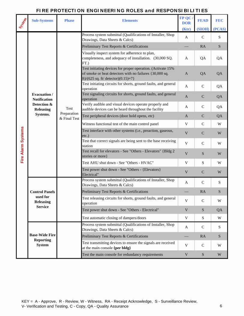
Process system submittal (Qualifications of Installer, Shop Drawings, Data Sheets & Calcs) A C S
Preliminary Test Reports & Certifications — RA S
Visually inspect system for adherence to plan, completeness, and adequacy of installation. (30,000 SQ. FT.)
A QA QA
Test initiating devices for proper operation. (Activate 15% of smoke or heat detectors with no failures {30,000 sq. ft)/(625 sq. ft/ detector)(0.15)=7}
A QA QA
Test initiating circuits for shorts, ground faults, and general operation A C QA
Test signaling circuits for shorts, ground faults, and general operation A C QA
Verify audible and visual devices operate properly and audible devices can be heard throughout the facility A C QA
Test peripheral devices (door hold opens, etc) A C QA
Witness functional test of the main control panel V C W
Test interface with other systems (i.e., preaction, gaseous, etc.) V C W
Test that correct signals are being sent to the base receiving station V C W
Test recall for elevators - See "Others - Elevators" {Bldg 2 stories or more} V S W
Test AHU shut down - See "Others - HVAC" V S W
Test power shut down - See "Others - {Elevators} Electrical" V C W
Process system submittal (Qualifications of Installer, Shop Drawings, Data Sheets & Calcs) A C S
Preliminary Test Reports & Certifications — RA S
Test releasing circuits for shorts, ground faults, and general operation V C W
Test power shut down - See "Others - Electrical" V S QA
Test automatic closing of dampers/doors V S W
Process system submittal (Qualifications of Installer, Shop Drawings, Data Sheets & Calcs) A C S
Preliminary Test Reports & Certifications — RA S
Test transmitting devices to ensure the signals are received at the main console {per bldg} V C W
Test the main console for redundancy requirements V S W
Test Preparation & Final Test
Control Panels used for
Releasing Service
Evacuation / Notification Detection &
Releasing Systems.
Fire
Ala
rm S
yste
ms
Base-Wide Fire Reporting
System
KEY = A - Approve, R - Review, W - Witness, RA - Receipt Acknowledge, S - Surveillance Review, V- Verification and Testing, C - Copy, QA - Quality Assurance 6
FIRE PROTECTION ENGINEERING ROLES and RESPONSIBILITIES
Sub-Systems Phase Elements FP QC / DOR FEAD FEC
(Ktr) (SIOH) (PCAS)Syste
m
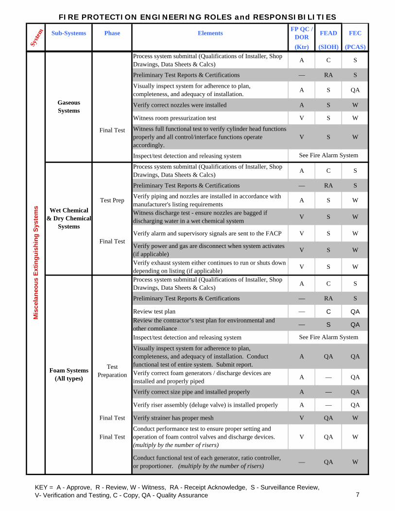
Process system submittal (Qualifications of Installer, Shop Drawings, Data Sheets & Calcs) A C S
Preliminary Test Reports & Certifications — RA S
Visually inspect system for adherence to plan, completeness, and adequacy of installation. A S QA
Verify correct nozzles were installed A S W
Witness room pressurization test V S W
Witness full functional test to verify cylinder head functions properly and all control/interface functions operate accordingly.
V S W
Inspect/test detection and releasing system
Process system submittal (Qualifications of Installer, Shop Drawings, Data Sheets & Calcs) A C S
Preliminary Test Reports & Certifications — RA S
Test Prep Verify piping and nozzles are installed in accordance with manufacturer's listing requirements A S W
Witness discharge test - ensure nozzles are bagged if discharging water in a wet chemical system V S W
Verify alarm and supervisory signals are sent to the FACP V S W
Verify power and gas are disconnect when system activates (if applicable) V S W
Verify exhaust system either continues to run or shuts down -depending on listing (if applicable) V S W
Process system submittal (Qualifications of Installer, Shop Drawings, Data Sheets & Calcs) A C S
Preliminary Test Reports & Certifications — RA S
Review test plan — C QAReview the contractor’s test plan for environmental and other compliance — S QA
Inspect/test detection and releasing system
Visually inspect system for adherence to plan, completeness, and adequacy of installation. Conduct functional test of entire system. Submit report.
A QA QA
Verify correct foam generators / discharge devices are installed and properly piped A — QA
Verify correct size pipe and installed properly A — QA
Verify riser assembly (deluge valve) is installed properly A — QA
Final Test Verify strainer has proper mesh V QA W
Final TestConduct performance test to ensure proper setting and operation of foam control valves and discharge devices. (multiply by the number of risers)
V QA W
Conduct functional test of each generator, ratio controller, or proportioner. (multiply by the number of risers) — QA W
See Fire Alarm System
Final Test
Final Test
See Fire Alarm System
Test Preparation
Mis
cela
neou
s Ex
tingu
ishi
ng S
yste
ms
Foam Systems (All types)
Wet Chemical & Dry Chemical
Systems
Gaseous Systems
KEY = A - Approve, R - Review, W - Witness, RA - Receipt Acknowledge, S - Surveillance Review, V- Verification and Testing, C - Copy, QA - Quality Assurance 7

FIRE PROTECTION ENGINEERING ROLES and RESPONSIBILITIES
Sub-Systems Phase Elements FP QC / DOR FEAD FEC
(Ktr) (SIOH) (PCAS)Syste
m
Process system submittal (Qualifications of Installer, Shop Drawings, Data Sheets & Calcs) A C S
Preliminary Test Reports & Certifications — RA S
Inspect Lath & gypsum board installation A QA QA
Inspect fire-rated / smoke wall and/or floor penetrations A S QA
Inspect wall/ceiling/roof joint A S QAInspect/test fire & smoke damper installation and performance A S QA
Inspect fire doors and frames A QA QA
Verify installed locations of exit signs. A S QA
Verify installed locations of emergency lighting A S QA
Final Test Check performance of emergency lighting systems and battery back-up. A S QA
Emergency Generators
Check to ensure all life safety features on the emergency generator are provide with power in the required amount of time
A S QA
Verify elevator re-call to primary floor A S QA
Verify elevator re-call to alternate floor A S QA
Test power disconnect upon water flow V S QA
Verify signal in elevator cab activates V S QA
Verify smoke exhaust / smoke control system activates via appropriate initiating devices (IBC §1704) A S QA
Verify location of duct detectors and for proper installation A S QA
Perform operational test to show smoke exhaust / smoke control system functions as designed V S QA
Special Inspections for smoke control (IBC §1704) (See NFPA 92A & 92B, Chap. 8.) A W W
Perform operational test to verify detector functions properly and shuts down the correct AHU V S QA
Pre-Test Verify each detector associated with the electrical equipment disconnects power A S QA
Final Test Test power disconnect for associated electronic equipment V S QA
Exit Signs and Emergency
Lighting
Oth
er S
yste
ms
Life
Saf
ety
Feat
ures
Preliminary and Final
Inspections
Preliminary
Electrical
Fire / Smoke Barriers IBC
Inspections (Section 109)
Elevators
Smoke Control / Exhaust Systems
Test
Preliminary Test
Final Test
Pass
ive
KEY = A - Approve, R - Review, W - Witness, RA - Receipt Acknowledge, S - Surveillance Review, V- Verification and Testing, C - Copy, QA - Quality Assurance 8

MECHANICAL ENGINEERING ROLES and RESPONSIBILITIES
Sub-Systems Phase Elements ME QC / DOR FEAD FEC
(Ktr) (SIOH) (PCAS)Complete System - Verify contractor provided complete fuel oil system to the facility, including applications and permits
A QA —
Piping - Verify fuel oil piping meets requirements of International Mechanical Code. A QA —
Testing - Verify oil system testing meets requirements of NFPA 31. V W —
Piping - Verify fuel piping is either ASTM A 53 Type E (electric-resistance welded, Grade A or B) black steel; or ASTM A 53 Type S (seamless, Grade A or B) black steel; or API SPEC 5L, seamless, submerged-arc weld or gas metal-arc weld, Grade B, black ste
A RA —
Fuel Pumps - Verify fuel pumps comply with NEMA MG 1, NFPA 70, and are designed for use with hydrocarbon fuels.
A RA —
Fuel Pumps - Verify fuel pumps have a working pressure of 1896 kilopascals (275 psig) at 38 degrees C (100 degrees F).
A RA —
Fuel Meters - Verify fuel meters are continuous duty, positive displacement type, with electronic thermal compensation capability, suitable for outdoor installation.
A RA —
Fuel Meters - Verify fuel meters are designed for use with hydrocarbon fuels and have a working pressure of 1896 kilopascals (275 psig) at 38 degrees C (100 degrees F).
A RA —
Storage Tanks - Verify aboveground liquid fuel storage tanks are concrete encased or double wall in accordance with UL 142 and UL 2085 with secondary containment and leak monitoring of a capacity to meet the system requirements. Verify overfill/spill con
A RA/ QA S
Dispensing Tanks - Verify Liquid fuel dispensing tanks are concrete encased or double wall in accordance with UL 142 and UL 2085 with secondary containment and leak monitoring of a capacity to meet the system requirements. Verify overfill/spill containme
A RA/ QA S
Submittal Process
Pumps - Verify pumps that are not part of the burner assembly are positive dispacement type A RA —
Field Visit Oil Filter - Verify an oil filter is provided prior to oil entering appliance or pump. A QA QA
Field Visit Drip Legs - Verify drip legs are provided and properly installed prior to oil entering appliance or pump. A QA —
Submittal Process
Storage Tanks - Verify all storage tanks meet NFPA 31 requirements. A RA —
Natural Gas - ALL Field Visit
Complete System - Verify contractor provided complete natural gas system to the facility, including applications and permits
A QA —
Field VisitTesting - Verify system was tested at 1.5 times maximum working pressure, but not less than 350 kPa (50 PSI) per NFPA 54
V W —
Ene
rgy
Supp
ly S
yste
ms
Syste
m
Fuel Oil - Interior
Field Visit
Submittal Process
Submittal Process/ Field
Visit
Fuel Oil - ALL
Fuel Oil - Exterior
KEY = A - Approve, R - Review, W - Witness, RA - Receipt Acknowledge, S - Surveilance Review, V- Verification and Testing, C - Copy, QA - Quality Assurance 9

MECHANICAL ENGINEERING ROLES and RESPONSIBILITIES
Sub-Systems Phase Elements ME QC / DOR FEAD FEC
(Ktr) (SIOH) (PCAS)Syste
m
Natural Gas - Exterior
(Contractor installed piping)
Field Visit Piping - Verify exterior gas piping meets requirements of local natural gas utility A QA —
Submittal Process
Piping - Verify piping meets requirements of ASME B31.8, Gas Transmission and Distribution Piping Systems A RA —
Submittal Process
Piping - Verify the natural gas piping is either ASTM A 53, Type E (electric-resistance welded, Grade A or B) black steel piping or ASTM A 53 Type S (seamless, Grade A or B) black steel piping or ASTM D 2513, Grade PE2406 or PE3408 polyethylene piping an
A RA —
Field VisitMeter and Pressure Regulator - Verify meter and pressure regulator are provided in accordance with local utility requirements.
A QA —
Field Visit
Piping Identification - Verify polyethylene plastic tape manufactured specifically for warning and identifying buried utility lines are provided for non-metallic undergound piping systems
A QA —
Natural Gas - Interior
Submittal Process
Piping - Verify interior gas piping meets requirements of NFPA 54, National Fuel Gas Code A RA —
Propane - ALL Field VisitComplete System - Verify contractor provided complete propane system to the facility, including appropriate applications and permits.
A QA —
Propane - Exterior
Submittal Process
Piping - If piping is not provided by propane supplier, verify the propane piping is either ASTM A 53, Type E (electric-resistance welded, Grade A or B) black steel piping or ASTM A 53 Type S (seamless, Grade A or B) black steel piping or ASTM D 2513, Gr
A RA —
Submittal Process
Fittings - Confirm Polyethylene fittings meet ASTM D 2683for socket fittings or ASTM D 2513 for molded butt-fusion fittings
A RA —
Field Visit Tank - Verify propane tank capacity conforms to tank capacity submitted in shop drawings. A QA —
Submittal Process
Tank - If tank is not provided by propane supplier, verify propane tank material and installation comply with NFPA 58.
A RA —
Submittal Process
Tank - If tank is not provided by propane supplier, verify propane tank is ASME labeled. A QA —
Field Visit
Piping Identiication - Verify polyethylene plastic tape manufactured specifically for warning and identifying buried utility lines are provided for non-metallic undergound piping systems
A QA —
Ene
rgy
Supp
ly S
yste
ms (
cont
inue
d)
KEY = A - Approve, R - Review, W - Witness, RA - Receipt Acknowledge, S - Surveilance Review, V- Verification and Testing, C - Copy, QA - Quality Assurance 10
MECHANICAL ENGINEERING ROLES and RESPONSIBILITIES
Sub-Systems Phase Elements ME QC / DOR FEAD FEC
(Ktr) (SIOH) (PCAS)Syste
m
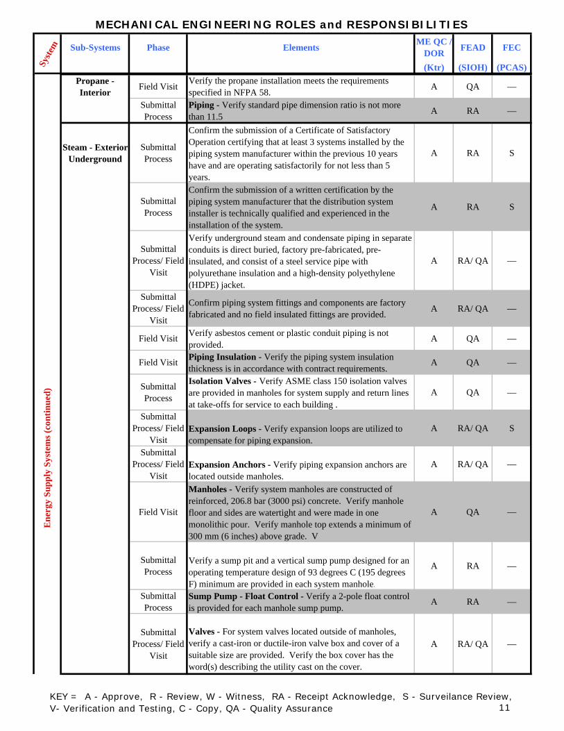
Propane - Interior Field Visit Verify the propane installation meets the requirements
specified in NFPA 58. A QA —
Submittal Process
Piping - Verify standard pipe dimension ratio is not more than 11.5 A RA —
Steam - Exterior Underground
Submittal Process
Confirm the submission of a Certificate of Satisfactory Operation certifying that at least 3 systems installed by the piping system manufacturer within the previous 10 years have and are operating satisfactorily for not less than 5 years.
A RA S
Submittal Process
Confirm the submission of a written certification by the piping system manufacturer that the distribution system installer is technically qualified and experienced in the installation of the system.
A RA S
Submittal Process/ Field
Visit
Verify underground steam and condensate piping in separate conduits is direct buried, factory pre-fabricated, pre-insulated, and consist of a steel service pipe with polyurethane insulation and a high-density polyethylene (HDPE) jacket.
A RA/ QA —
Submittal Process/ Field
Visit
Confirm piping system fittings and components are factory fabricated and no field insulated fittings are provided. A RA/ QA —
Field Visit Verify asbestos cement or plastic conduit piping is not provided.
A QA —
Field Visit Piping Insulation - Verify the piping system insulation thickness is in accordance with contract requirements.
A QA —
Submittal Process
Isolation Valves - Verify ASME class 150 isolation valves are provided in manholes for system supply and return lines at take-offs for service to each building .
A QA —
Submittal Process/ Field
VisitExpansion Loops - Verify expansion loops are utilized to compensate for piping expansion.
A RA/ QA S
Submittal Process/ Field
VisitExpansion Anchors - Verify piping expansion anchors are located outside manholes.
A RA/ QA —
Field Visit
Manholes - Verify system manholes are constructed of reinforced, 206.8 bar (3000 psi) concrete. Verify manhole floor and sides are watertight and were made in one monolithic pour. Verify manhole top extends a minimum of 300 mm (6 inches) above grade. V
A QA —
Submittal Process
Verify a sump pit and a vertical sump pump designed for an operating temperature design of 93 degrees C (195 degrees F) minimum are provided in each system manhole.
A RA —
Submittal Process
Sump Pump - Float Control - Verify a 2-pole float control is provided for each manhole sump pump.
A RA —
Submittal Process/ Field
Visit
Valves - For system valves located outside of manholes, verify a cast-iron or ductile-iron valve box and cover of a suitable size are provided. Verify the box cover has the word(s) describing the utility cast on the cover.
A RA/ QA —
Ene
rgy
Supp
ly S
yste
ms (
cont
inue
d)
KEY = A - Approve, R - Review, W - Witness, RA - Receipt Acknowledge, S - Surveilance Review, V- Verification and Testing, C - Copy, QA - Quality Assurance 11

MECHANICAL ENGINEERING ROLES and RESPONSIBILITIES
Sub-Systems Phase Elements ME QC / DOR FEAD FEC
(Ktr) (SIOH) (PCAS)Syste
m
Steam - Exterior Aboveground
Submittal Process
Piping - Verify steam piping is either ASTM A 53 Type E (electric-resistance welded, Grade A or B) black steel pipe or ASTM A 53 Type S (seamless, Grade A or B) black steel pipe or, for pipe sizes through 250 mm (9 inches), ASTM A 106 (Grade A or B) black
A RA —
Submittal Process
Piping - Verify condensate piping is either ASTM A 53 Type E (electric-resistance welded, Grade A or B) black steel, Weight Class XS (Extra Strong); or ASTM A 53 Type S (seamless, Grade A or B) black steel, Weight Class XS (Extra Strong); or ASTM A 106, G
A RA —
Field VisitPiping Insulation - Verify piping insulation is either fibrous glass, calcium silicate, or cellular glass as indicated in submitted shop drawings. Verify pipe insulation matches existing or surrounding insulation if applicable.
A QA —
Field Visit Piping Insulation - Verify the piping system insulation thickness is in accordance with contract requirements.
A QA —
Field VisitInsulation - Verify insulation is covered with an with aluminum jacket painted to conform with the Base Architectural Plan.
A QA —
Submittal Process/ Field
Visit
Verify the use of either MSS SP-58 or MSS SP-69 adjustable supports with insulation protection saddles. Verify roller supports utilize stainless steel axles.
A RA/ QA —
Field Visit Support Poles - Verify support poles are installed with guy wires and necessary hardware.
A QA —
Submittal Process/ Field
Visit
Pipe Expansion - Verify pipe expansion is compensated by utilizing either expansion loops, guided sliexpansion joints, or flexible ball type expansion joints.
A RA/ QA S
Steam - Interior Submittal Process
Steam piping - Verify is ASTM A106 or A53, Grade B, Schedule 40, black steel, electric-resistance welded or seamless
A RA —
Submittal Process/ Field
Visit
Steam piping - Verify insulated with mineral fiber or cellular glass insulation with all-purpose jacket A RA/ QA —
Submittal Process
Condensate return piping - Verify is ASTM A106 or ASTM A53, Grade B, Schedule 80, black steel, electric-resistance welded or seamless
A RA —
Submittal Process/ Field
Visit
Condensate return piping - Verify insulated with mineral fiber or cellular glass insulation with all-purpose jacket A RA/ QA —
Submittal Process
Steel pipe fittings - For piping 50 mm (2 inch) and smaller, verify is ANSI/ASME B16.3 malleable iron screwed fittings or ASME B16.11 socket welding (Class 3000) or ASME B16.11 threaded type (Class 2000)
A RA —
Submittal Process
Steel pipe fittings - For piping 63 mm (2-1/2 inch) and larger, verify is ANSI/ASME B16.9 butt-welding fittings or ANSI/ASME B16.5 flanged type
A RA —
Field Visit Steam pressure reducing station - Verify provided for each building A QA —
Ene
rgy
Supp
ly S
yste
ms (
cont
inue
d)
KEY = A - Approve, R - Review, W - Witness, RA - Receipt Acknowledge, S - Surveilance Review, V- Verification and Testing, C - Copy, QA - Quality Assurance 12

MECHANICAL ENGINEERING ROLES and RESPONSIBILITIES
Sub-Systems Phase Elements ME QC / DOR FEAD FEC
(Ktr) (SIOH) (PCAS)Syste
m
Submittal Process/ Field
Visit
Steam traps - Verify steam traps and accessories are in accordance with UFC 3-400-10N A RA/ QA —
Field Visit Verify all valves, traps, and PRV's are accessible for service & maintenance A QA —
Hot Water - Exterior
Underground
Submittal Process/ Field
Visit
Piping - Verify underground hot water supply & return piping in separate conduits is direct buried, factory pre-fabricated, pre-insulated, and consist of a steel service pipe with polyurethane insulation and a high-density polyethylene (HDPE) jacket.
A RA/ QA —
Submittal Process/ Field
Visit
Confirm piping system fittings and components are factory fabricated and no field insulated fittings are provided. A RA/ QA —
Field Visit Verify asbestos cement or plastic conduit piping is not provided.
A QA —
Submittal Process
The UHDS representative shall be certified in writing by the UHDS manufacturer to be technically qualified and experienced in the installation of the system. Provide a Certificate of Satisfactory Operation certifying that at least 3 systems installed by
A QA S
Field Visit Piping Insulation - Verify the piping system insulation thickness is in accordance with contract requirements.
A QA —
Submittal Process/ Field
Visit
Isolation Valves - Verify ASME class 150 isolation valves are provided in manholes for system supply and return lines at take-offs for service to each building .
A RA/ QA —
Submittal Process/ Field
VisitExpansion Loops - Verify expansion loops are utilized to compensate for piping expansion.
A RA/ QA S
Submittal Process/ Field
Visit
Manholes - Verify system manholes are constructed of reinforced, 206.8 bar (3000 psi) concrete. Verify manhole floor and sides are watertight and were made in one monolithic pour. Verify manhole top extends a minimum of 300 mm (6 inches) above grade. V
A RA/ QA —
Submittal Process
Verify a sump pit and a vertical sump pump designed for an operating temperature design of 93 degrees C (195 degrees F) minimum are provided in each system manhole.
A RA —
Submittal Process
Sump Pump - Float Control - Verify a 2-pole float control is provided for each manhole sump pump.
A RA —
Submittal Process/ Field
Visit
Valves - For system valves located outside of manholes, verify a cast-iron or ductile-iron valve box and cover of a suitable size are provided. Verify the box cover has the word(s) describing the utility cast on the cover.
A RA/ QA —
nerg
y Su
pply
Sys
tem
s (co
ntin
ued)
KEY = A - Approve, R - Review, W - Witness, RA - Receipt Acknowledge, S - Surveilance Review, V- Verification and Testing, C - Copy, QA - Quality Assurance 13

MECHANICAL ENGINEERING ROLES and RESPONSIBILITIES
Sub-Systems Phase Elements ME QC / DOR FEAD FEC
(Ktr) (SIOH) (PCAS)Syste
m
Hot Water - Exterior
Aboveground
Submittal Process
Piping - Verify hot water piping is either ASTM A 53 Type E (electric-resistance welded, Grade A or B) black steel, Weight Class XS (Extra Strong); or ASTM A 53 Type S (seamless, Grade A or B) black steel, Weight Class XS (Extra Strong); or ASTM A 106, Gr
A RA —
Field VisitPiping Insulation - Verify piping insulation is either fibrous glass, calcium silicate, or cellular glass as indicated in submitted shop drawings.
A QA —
Field Visit Piping Insulation - Verify the piping system insulation thickness is in accordance with contract requirements.
A QA —
Field VisitInsulation - Verify insulation is covered with an with aluminum jacket painted to conform with the Base Architectural Plan.
A QA —
Submittal Process/ Field
Visit
Pipe Expansion - Verify pipe expansion is compensated by utilizing either expansion loops, guided slip expansion joints, or flexible ball type expansion joints.
A RA/ QA S
Submittal Process/ Field
Visit
Verify the use of either MSS SP-58 or MSS SP-69 adjustable supports with insulation protection saddles. Verify roller supports utilize stainless steel axles.
A RA/ QA —
Field VisitSupport Poles - Verify support poles are installed with guy wires and necessary hardware. A QA —
Hot Water - Interior
Submittal Process
Piping - Verify hot water piping is electric resistance, welded or seamless, schedule 40, black steel pipe conforming to ASTM A53. Piping 100mm (4 inch) and smaller may be ASTM B 88 Type K or L copper.
A RA —
Submittal Process
Steel fittings - For piping 50mm (2 inch) and smaller, verify provided ANSI/ASME B16.3 malleable iron screwed fittings OR ASME B16.11 socket welding (Class 3000) fittings OR ASME B16.11 threaded type (Class 2000)
A RA —
Submittal Process
Steel fittings - For piping 63 mm (2-1/2 inch) and larger, verify provided ANSI/ASME B16.9 butt-welding fittings OR ANSI/ASME B16.5 flanged type
A RA —
Submittal Process
Copper fittings - Verify ANSI B16.18 cast bronze solder joint type or ASME/ANSI B16.22 wrought copper solder joint type
A RA —
En
KEY = A - Approve, R - Review, W - Witness, RA - Receipt Acknowledge, S - Surveilance Review, V- Verification and Testing, C - Copy, QA - Quality Assurance 14

MECHANICAL ENGINEERING ROLES and RESPONSIBILITIES
Sub-Systems Phase Elements ME QC / DOR FEAD FEC
(Ktr) (SIOH) (PCAS)Syste
m
Submittal Process/ Field
Visit
Insulation - Verify hot water piping insulated with mineral fiber insulation with factory-applied all-purpose jacket A RA/ QA —
Field Visit Isolation valves - Verify equipment provided with isolation valves for service and repairs A QA —
Submittal Process/ Field
VisitValves - Verify appropriately sized A RA/ QA —
Submittal Process/ Field
Visit
Balancing valves - Verify provided and appropriately sized to balance water flow A RA/ QA QA
Field Visit Appurtenances - Verify provided (such as air separators, expansion tanks, suction diffusers, strainers, etc) A QA —
Field Visit Test ports - Verify provided in piping at inlet and outlet of all major system components including boilers, pumps, etc) A QA QA
Field Visit Verify all valves and test ports are accessible for service and maintenance A QA —
Chilled Water & Condenser
Water - Exterior
Underground
Submittal Process
Verify system provided is direct buried, factory-prefabricated, pre-insulated, chilled water piping systems. Verify all fittings and accessories are designed and factory-fabricated to prevent moisture from entering into the system by manufacturer.
A RA S
Field Visit Verify backfill and overall installation meets the requirements of the piping system manufacturer.
A QA —
Field VisitIsolation Valves - Verify supply and return line isolation valves are provided at take-offs for service to each building in valve boxes.
A QA —
Submittal Process/ Field
Visit
Verify expansion loops are provided to compensate for piping expansion. Verify anchors are provided outside manholes.
A RA/ QA S
Chilled Water & Condenser
Water - Exterior
Aboveground
Submittal Process
Piping - Verify chilled and condenser water piping are either electric resistance welded or seamless Schedule 40 black steel pipe conforming to ASTM A 53 or, for piping 100 mm (4 inch) and smaller, ASTM B 88 Type K or L copper.
A RA —
Submittal Process
If steel piping is used, verify for piping 50 mm (2 inch) and smaller, ANSI/ASME B16.3 malleable iron screwed fittings or ASME B16.11 socket welding (Class 3000) or threaded type (Class 2000) fittings are provided. For piping 63 mm (2-1/2 inch) and large
A RA —
Submittal Process
If copper piping is used, verify ANSI B16.18 cast bronze solder joint fittings or ASME/ANSI B16.22 wrought copper solder joint fittings are provided.
A RA —
Submittal Process/ Field
Visit
Piping Insulation - Verify piping insulation is either Mineral fiber, Urethane, cellular glass, Faced Phenolic Foam, or Flexible Cellular pipe insulation as indicated in submitted shop drawings.
A RA/ QA —
Ene
rgy
Supp
ly S
yste
ms (
cont
inue
d)
KEY = A - Approve, R - Review, W - Witness, RA - Receipt Acknowledge, S - Surveilance Review, V- Verification and Testing, C - Copy, QA - Quality Assurance 15

MECHANICAL ENGINEERING ROLES and RESPONSIBILITIES
Sub-Systems Phase Elements ME QC / DOR FEAD FEC
(Ktr) (SIOH) (PCAS)Syste
m
Field Visit Piping Insulation - Verify the piping system insulation thickness is in accordance with contract requirements.
A QA —
Field Visit Piping Insulation - Verify piping insulation is covered with an aluminum jacket.
A QA —
Submittal Process/ Field
Visit
Verify the use of either MSS SP-58 or MSS SP-69 adjustable supports with insulation protection saddles. Verify roller supports utilize stainless steel axles.
A RA/ QA —
Field Visit Support Poles - Verify support poles are installed with guy wires and necessary hardware.
A QA —
Submittal Process/ Field
Visit
Pipe Expansion - Verify pipe expansion is compensated by utilizing either expansion loops, guided slip expansion joints, or flexible ball type expansion joints.
A RA/ QA S
Chilled Water & Condenser
Water - Interior
Submittal Process
Aboveground chilled & condenser water piping - Verify aboveground chilled water piping is electric resistance welded or seamless schedule 40 black steel pipe conforming to ASTM A 53. Piping 100mm (4 inch) and smaller may be ASTM B 88 Type K or L copper.
A RA —
Submittal Process
Steel pipe fittings - For piping 50mm (2 inch) and smaller - Verify provided ANSI/ASME B16.3 malleable iron screwed fittings or ASME B16.11 socket welding (Class 3000) or threaded type (Class 2000).
A RA —
Submittal Process
Steel pipe fittings - For piping 63mm (2-1/2 inch) and larger - Verify provided ASME/ANSI B16.9 butt-welding fittings or ASME/ANSI B16.5 flanged type.
A RA —
Submittal Process
Steel pipe fittings - Grooved joint pipe coupling systems of appropriate pressure rating are acceptable in lieu of welded or screwed fittings
A RA —
Submittal Process
Copper fittings - Verify provided ANSI B16.18 cast bronze solder joint type or ASME/ANSI B16.22 wrought copper solder joint type
A RA —
Field VisitIsolation valves - Verify isolation valves provided on supply and return lines at take-offs for service to each building
A QA —
Field Visit Isolation valves - Verify isolation valves located in valve boxes A QA —
Submittal Process/ Field
Visit
Insulation - Verify above-ground chilled water piping insulated with cellular glass insulation. Flexible unicellular insulation may be used on small piping runouts.
A RA/ QA —
Submittal Process/ Field
Visit
Insulation - Verify above-ground condenser water piping insulated with mineral fiber insulation A RA/ QA —
Submittal Process/ Field
Visit
Insulation - Verify all-purpose jacket with vapor retarder provided for above-ground chilled water and condenser piping
A RA/ QA —
Submittal Process/ Field
VisitValves - Verify appropriately sized A RA/ QA —
Ene
rgy
Supp
ly S
yste
ms (
cont
inue
d)in
ued)
KEY = A - Approve, R - Review, W - Witness, RA - Receipt Acknowledge, S - Surveilance Review, V- Verification and Testing, C - Copy, QA - Quality Assurance 16

MECHANICAL ENGINEERING ROLES and RESPONSIBILITIES
Sub-Systems Phase Elements ME QC / DOR FEAD FEC
(Ktr) (SIOH) (PCAS)Syste
m
Submittal Process/ Field
Visit
Balancing valves - Verify provided and appropriately sized to balance water flow A RA/ QA QA
Submittal Process/ Field
VisitRelief valves - Verify provided and appropriately sized A RA/ QA —
Field VisitTest ports - Verify test ports provided inpiping at inlet and outlet of all major system components including chillers, pumps, etc
A QA QA
Field Visit Verify all valves and test ports are accessible for service and maintenance A QA —
AHU's - ALL Field Visit DDC Sensors - Confirm location of DDC sensors (temp, SP, Freeze, High pressure SP, AFM), if required A QA QA
Field Visit Smoke Detectors - Confirm location of smoke detectors (if over 2000 cfm) A QA QA
Field Visit Testing - Filters - Confirm filters are clean prior to testing A QA QA
Field Visit Filters - Confirm filters are installed — — —Field Visit Belts - Confirm belt tightness and alignment A QA QAField Visit Coils - Confirm all coils are clean A QA QA
Field Visit Vibration Isolators - Confirm vibration isolators installed according to contract docs and unit secured A QA QA
Field Visit Damper - Confirm damper operation and assembly tightness A QA QA
Field Visit Motor - Confirm motor size (HP), voltage, amperage, and rpm A QA QA
Submittal Process
Fans - Verify provided have AMCA 210 certified fans with AMCA seal A QA —
Field Visit Fans - Confirm fan rpm and rotation direction A QA QA
Field Visit OA Intake Plenum - Confirm OA intake plenum configuration provides for drainage A QA QA
Field Visit AFM - Confirm air flow monitoring station location in conformance with manufacturer requirements A QA QA
Field Visit Size - Confirm unit matches schedule req A QA QASubmittal
Process/ Field Visit
Fan bearings - Verify fan bearings were greased (if req) and have min average life of 200,000 hours at design operating conditions
A RA/ QA —
Field Visit Birdscreens - Verify birdscreens provided for outdoor inlets and outlets A QA QA
Field Visit Verify all filter and access doors are accessible for service and maintenance A QA —
Field Visit Verify provided are modular construction, double wall AHU's with min of 25mm (1 inch) casing insulation A QA —
Submittal Process
Verify provided have ARI 430 certified fans and ARI certified coils A RA —
Ene
rgy
Supp
ly S
yste
ms (
cont
i
KEY = A - Approve, R - Review, W - Witness, RA - Receipt Acknowledge, S - Surveilance Review, V- Verification and Testing, C - Copy, QA - Quality Assurance 17

MECHANICAL ENGINEERING ROLES and RESPONSIBILITIES
Sub-Systems Phase Elements ME QC / DOR FEAD FEC
(Ktr) (SIOH) (PCAS)Syste
m
Submittal Process/ Field
Visit
Drain pan - Verify provided has stainless steel, positive draining condensate drain pan A RA/ QA —
Submittal Process
For 100% OA units - Verify capability provided for cooling, heating, dehumidification, and reheat A RA —
Submittal Process/ Field
Visit
Ultraviolet disinfection system - Verify central station ahu's provided with an ultraviolet c-band (UVC) disinfection system for mold, bacteria, and odor control in each air handler that has a chilled water or DX cooling coil
A RA/ QA —
Submittal Process/ Field
Visit
Ultraviolet disinfection system - Verify irradiation emitters and fixtures installed in sufficient quantity and in such an arrangement so as to provide an equal distribution of UVC energy on the coil and in the drain pan
A RA/ QA —
Submittal Process/ Field
Visit
Ultraviolet disinfection system - Verify the UVC energy produced has the lowest possible reflected and shadowed losses (To maintain energy efficiency)
A RA/ QA —
Submittal Process/ Field
Visit
Ultraviolet disinfection system - For energy efficiency, verify power supplies are of the high efficiency electronic type and matched to the emitter
A RA/ QA —
Submittal Process/ Field
Visit
Ultraviolet disinfection system - For intensity, verify the minimal UVC energy striking the leading edge (if nstalled upstream) or trailing edge (if installed downstream) of all the coil fins is not less than 820 uW/cm2 at the closest point and through pl
A RA/ QA —
Submittal Process/ Field
Visit
Ultraviolet disinfection system - Verify equal amounts strike the drain pan, either directly or indirectly through reflection
A RA/ QA —
Submittal Process/ Field
Visit
Ultraviolet disinfection system - For installation, verify emitters and fixtures are installed at right angles to the conforming lines of the coil fins, such that through incident angle reflection, UVC energy bathes all surfaces of the coil and drain pan
A RA/ QA —
Submittal Process/ Field
Visit
Ultraviolet disinfection system - Verify one complete set of spare bulbs supplied A RA/ QA —
AHU's - Split System
Submittal Process
Verify provided is factory assembled, packaged AHU rated in accordance with ARI 210/240 or ARI 340/360 A RA —
Field Visit Verify matching components provided are from the same manufacturer A QA —
AHU's - Rooftop
Submittal Process/ Field
Visit
Verify provided is factory packaged unit in accordance with ARI 430 and suitable for outdoor installation A RA/ QA —
Field Visit Roof Curb - Verify provided with manufacturer's roof curb A QA —
Equ
ipm
ent &
Com
pone
nts (
cont
inue
d)
KEY = A - Approve, R - Review, W - Witness, RA - Receipt Acknowledge, S - Surveilance Review, V- Verification and Testing, C - Copy, QA - Quality Assurance 18

MECHANICAL ENGINEERING ROLES and RESPONSIBILITIES
Sub-Systems Phase Elements ME QC / DOR FEAD FEC
(Ktr) (SIOH) (PCAS)Syste
m
Roof Curbs Field Visit Mounting Surface - Confirm fan or unit mounting surface is parallel to the horizon, not the roof deck if sloped A QA —
Field Visit Waterproofing - Confirm curb has been flashed properly and seal to the roofing material (no leaks) (waterproofing) A QA —
Field Visit Lightning Rods - Confirm lightning rods have been attached to units and run to ground A QA —
Field Visit Insulation - Confirm roof curb is insulated A QA —
Field Visit Size - Confirm curb is the same size or smaller as the unit being placed on it (tight fit) A QA —
Fans - ALLSubmittal
Process/ Field Visit
Verify fans are AMCA 210 certified with AMCA seal A RA/ QA —
Submittal Process
Fan bearings - Verify fan bearings have min average life of 200,000 hours at design operating conditions A RA —
Field Visit Rotation - Confirm rotation and alignment A QA QAField Visit Belts - Confirm belt tightness (if provided) A QA QAField Visit Motor - Confirm HP, voltage, amperage A QA QAField Visit Size - Confirm size matches schedule req A QA QAField Visit Verify fans are accessible for service and maintenance A QA
Field Visit Birdscreens - Verify bird screens provided for outdoor inlets and outlets A QA QA
Field Visit DDC - Verify fans provided with means for verifying operation via DDC system A QA QA
Exhaust Fans (Roof) Field Visit Roof Curb - Confirm lag bolted to roof curb A QA QA
Field Visit Dome Top - Confirm dome top is secured A QA QAField Visit Type - Verify centrifugal fans provided A QA
In-line Fans Field Visit Vibration Isolators - Confirm hangers & isolation devices A QA QA
Field Visit Flex Connection - Confirm flexible connection to ductwork A QA QA
Field Visit Speed Controller - Confirm speed controller installation (if provided) A QA QA
Field Visit Access Panel - Confirm access panel located properly A QA QAField Visit Type - Verify centrifugal fans provided A QA —
Wall Fans Field Visit Type - Verify wall fans provided are propeller fans with fan guards A QA —
Field Visit Type - Verify wall fans provided are centrifugal fans with backdraft dampers and wall bracket A QA —
Bathroom FanSubmittal
Process/ Field Visit
Verify provided are UL 507 and UL-Listed, Home Ventilating Institute (HVI) certified, and with AMCA seal for ceiling installation
A RA/ QA —
men
t & C
ompo
nent
s (co
ntin
ued)
KEY = A - Approve, R - Review, W - Witness, RA - Receipt Acknowledge, S - Surveilance Review, V- Verification and Testing, C - Copy, QA - Quality Assurance 19

MECHANICAL ENGINEERING ROLES and RESPONSIBILITIES
Sub-Systems Phase Elements ME QC / DOR FEAD FEC
(Ktr) (SIOH) (PCAS)Syste
m
Range HoodsSubmittal
Process/ Field Visit
Verify provided are UL 507 and UL-Listed, with AMCA seal A RA/ QA —
Submittal Process/ Field
VisitLight - Verify provided with light over stove A RA/ QA —
Submittal Process
Verify min fan capacity is 160 cfm with max sound level of 5.6 sones A RA —
Louvers & Hoods - ALL
Submittal Process
Louver rating - Verify louvers bear AMCA ratings seal for air performance and water penetration in accordance with AMCA 500 and AMCA 511
A RA —
Submittal Process/ Field
Visit
Construction - Verify hoods and louvers constructed of anodized aluminum alloy or stainless steel A RA/ QA
Submittal Process/ Field
VisitBirdscreens - Verify provided for louvers and hoods A RA/ QA QA
Intake Hood (Roof)
Submittal Process/ Field
VisitType - Confirm type as specified A RA/ QA QA
Field Visit Confirm top is secured A QA QASubmittal
Process/ Field Visit
Size - Confirm size matches schedule req (free area) A RA/ QA QA
OA Intake Louvers (Wall)
Submittal Process/ Field
VisitType - Confirm type as specified A RA/ QA QA
Submittal Process/ Field
VisitSize - Confirm size matches schedule req (free area) A RA/ QA QA
Submittal Process/ Field
Visit
Confirm waterproof (when req) and velocity when water carry-over occurs A RA/ QA QA
Field Visit Intake Plenum - Confirm intake plenum is sloped back to louver or drain has been provided A QA QA
Field Visit Damper - Confirm opposed blade damper with actuator has been provided A QA QA
Field Visit AFM - Confirm air flow monitoring type louver has been provided, if req A QA QA
Equ
ipm
KEY = A - Approve, R - Review, W - Witness, RA - Receipt Acknowledge, S - Surveilance Review, V- Verification and Testing, C - Copy, QA - Quality Assurance 20

MECHANICAL ENGINEERING ROLES and RESPONSIBILITIES
Sub-Systems Phase Elements ME QC / DOR FEAD FEC
(Ktr) (SIOH) (PCAS)Syste
m
Ductwork Field VisitConstruction - Except as specified herein, verify ductwork constructed, braced, reinforced, installed, supported, and sealed per SMACNA standards
A QA QA
Field Visit Verify all dampers are accessible for service and maintenance A QA —
Field Visit Confirm general construction conforms to contract documents A QA QA
Field Visit Confirm correct pressure rating of ductwork has been conformed to SMACNA A QA QA
Field Visit Confirm ductwork has been sealed in accordance with specified seal class A QA QA
Field Visit VAV inlet - Confirm minimum straight duct is 6 duct diameters and same size as VAV terminal inlet A QA QA
Field Visit Confirm DALT allowables are met A QA QASubmittal
Process/ Field Visit
Access Doors - Confirm access doors have been provided before every elbow with turning vanes A RA/ QA QA
Submittal Process/ Field
Visit
Access Doors - Confirm access doors provided at appropriate locations A RA/ QA QA
Field VisitFlexible duct - Verify insulated flexible duct used only to adapt to minor offsets for connections to air distribution devices
A QA QA
Submittal Process
Flexible duct - Verify is UL 181 listed and per SMACNA DCS with minimum R value of 4 A RA —
Field Visit Flexible duct - Verify maximum length is 2 meters (6 feet) A QA QA
Field Visit
Flexible Duct - Confirm, where flexible ductwork is specified, that the length of flex ductwork is provided to the max req length or less and is supported properly with no abrupt turns (ie: as straight as possible)
A QA QA
Field Visit Flexible connectors - Verify provided between fans and ducts A QA QA
Submittal Process/ Field
Visit
Damper - Confirm balancing damper at branch take-off's, not at diffuser neck A RA/ QA QA
Submittal Process/ Field
Visit
Damper - Confirm balancing damper construction conforms to the specified seal class A RA/ QA QA
Submittal Process/ Field
Visit
Damper - Confirm discharge damper installed on VAV terminal discharge, if req A RA/ QA QA
Field Visit Damper - Confirm control damper type and location along with actuator type A QA QA
Submittal Process Dampers - Verify conforms to SMACNA DCS A RA —
Submittal Process Fire dampers - Verify are rated per UL 555 A RA —
Submittal Process
Fire dampers - Verify are dynamic type rated for closure against a moving airstream A RA —
Equ
ipm
ent &
Com
pone
nts (
cont
inue
d)
KEY = A - Approve, R - Review, W - Witness, RA - Receipt Acknowledge, S - Surveilance Review, V- Verification and Testing, C - Copy, QA - Quality Assurance 21

MECHANICAL ENGINEERING ROLES and RESPONSIBILITIES
Sub-Systems Phase Elements ME QC / DOR FEAD FEC
(Ktr) (SIOH) (PCAS)Syste
m
Submittal Process/ Field
Visit
Fire dampers - Verify do not intrude into air stream when in open position A RA/ QA —
Submittal Process Smoke dampers - Verify are rated per UL 555S A RA —
Submittal Process/ Field
Visit
Elbows - Confirm correct elbow type (ie: double wall turning vane, 1.5 radius curved, etc) A RA/ QA QA
Field Visit Bracing - Confirm proper bracing of high pressure ductwork in accordance with SMACNA A QA QA
Field Visit Filters - Confirm access to filter rack for ease of filter change out in duct mounted assemblies A QA QA
Submittal Process/ Field
Visit
Insulation - Confirm ductwork insulated properly (ext batt, hard, int lined, double wall insulated, etc) A RA/ QA QA
Field Visit Insulation - Inspect vapor barrier of insulation A QA —
Field Visit Hangers - Confirm proper duct hangers have been utilized in accordance with spec req A QA QA
Field VisitVibration Isolators - Confirm the use of vibration isolation material at unit connection to ductwork free of holes (no leakage)
A QA QA
Submittal Process
Sound attenuators - Verify fabricated sound attenuators reduces the rated sound pressure level of the fan down to at least 65 decibels in the 250 Hz (third octave band) center frequency by using a reference sound source calibrated in decibels of sound pow
A RA —
Submittal Process/ Field
Visit
Sound attenuators - Verify pressure drop does not exceed 157 Pa (0.63 inch of water) A RA/ QA QA
VAV Boxes - ALL
Submittal Process
Verify units are pressure-independent type and rated per ARI 880 A QA —
Field Visit Primary air valve - Verify not allowed to fully shut-off A QA QA
Field Visit Heating coil - Verify each box provided with heating coil unless not required by space reheat or heating A QA —
Field Visit Verify all VAV box control panels are accessible A QAField Visit Electronic controls - Verify are provided A QA QA
VAV Terminal Box (Fan-Powered)
Submittal Process
Type - Verify units are pressure-independent, fan powered, rated per ARI 880, and UL listed A QA —
Field Visit Filters - Confirm filter installed and clean A QA QA
Field Visit Confirm ductwork on primary inlet is installed with 6 straight duct diameters the same size as the inlet A QA QA
Submittal Process/ Field
Visit
Dampers - Confirm discharge damper has been provided and/or coordinated with sheet metal contractor A QA QA
Field Visit Confirm fan size & primary inlet sized in accordance with contract documents A QA —
Field Visit Primary Air Valve - Confirm max/min setting of primary air valve A QA QA
Field Visit Primary air valve - Verify not allowed to fully shut-off A QA QAent &
Com
pone
nts (
cont
inue
d)
KEY = A - Approve, R - Review, W - Witness, RA - Receipt Acknowledge, S - Surveilance Review, V- Verification and Testing, C - Copy, QA - Quality Assurance 22

MECHANICAL ENGINEERING ROLES and RESPONSIBILITIES
Sub-Systems Phase Elements ME QC / DOR FEAD FEC
(Ktr) (SIOH) (PCAS)Syste
m
Field Visit Size - Confirm size matches schedule req A QA QA
Field Visit Motor - Confirm HP, voltage, and amperage of fan motor A QA QA
Field Visit Heating coil - Verify each box provided with heating coil, if required A QA —
Field Visit Reheat Coils - Confirm reheat coil size, if req A QA —Field Visit Reheat Coils - Confirm reheat coil is piped properly A QA QA
Field Visit Sensors - Confirm discharge temp sensor provided, if req A QA QA
Field Visit Confirm hangers have provisions for vibration isolation A QA QA
Field VisitElectronic controls - Verify provided with speed controller, discharge volume control damper(s), and return/recirculation air frame and filter
A QA QA
Submittal Process Insulation - Verify in accordance with ASHRAE 90.1 A RA —
VAV Terminal Box (Shut Off) Field Visit Confirm ductwork on primary inlet is installed with 6
straight duct diameters the same size as the inlet A QA QA
Field Visit Primary Air Valve - Confirm max and min setting of primary air valve A QA QA
Field Visit Reheat Coils - Confirm reheat coil size, if req A QAField Visit Reheat Coils - Confirm reheat coil in piping properly A QA QA
Field Visit Sensors - Confirm discharge temp sensor provided, if req A QA QA
Field Visit Confirm hangers have provisions for vibration isolation A QA QAField Visit Size - Confirm box size matches schedule req A QA QA
DX VAV Units Submittal Process
Finish - If indicated in ESR Section D30, verify anti-corrosion coating provided is immersion applied, baked phenolic, or other approved coating. Field applied coatings not acceptable.
A QA —
Submittal Process/ Field
Visit
Direct expansion equipment - Verify is specifically designed and manufactured for VAV applications A RA/ QA —
Submittal Process/ Field
Visit
Equipment - Verify from the same manufacturer (central air handling units, VAV boxes/ zone dampers, and zone controls)
A RA/ QA —
Field Visit Evaporator coils - Verify airflow through evaporator coils is not modulated A QA —
Field VisitZone control damper units - Verify duct mounted zone control damper units provided with integral control box designed for use with DX VAV packaged systems
A QA —
Submittal Process/ Field
Visit
Air diffusers - Verify self-modulating air diffusers are not used A RA/ QA —
Condensing Units
Submittal Process/ Field
Visit
Finish - If indicated in ESR Section D30, verify anti-corrosion coating provided is immersion applied, baked phenolic, or other approved coating. Field applied coatings not acceptable.
A RA/ QA —
Submittal Process
Air conditioner - Verify air-cooled, split system air conditioner provided with ducted air distribution A QA —
Equ
ipm
ed)
KEY = A - Approve, R - Review, W - Witness, RA - Receipt Acknowledge, S - Surveilance Review, V- Verification and Testing, C - Copy, QA - Quality Assurance 23

MECHANICAL ENGINEERING ROLES and RESPONSIBILITIES
Sub-Systems Phase Elements ME QC / DOR FEAD FEC
(Ktr) (SIOH) (PCAS)Syste
m
Submittal Process
Construction and rating - Verify units are factory assembled, designed, tested, and rated in accordance with ARI 210/ 240 or ARI 340/ 360
A QA —
Submittal Process/ Field
Visit
Clearance - Verify manufacturer's minimum recommended clearance around condensing units is provided A RA/ QA QA
Field Visit Refrigerant piping size - Verify is per manufacturer's recommendations A QA —
Heat Pumps - Ground Source
Submittal Process/ Field
Visit
Finish - If indicated in ESR Section D30, verify anti-corrosion coating provided is immersion applied, baked phenolic, or other approved coating. Field applied coatings not acceptable.
A RA/ QA —
Submittal Process
Construction and rating - Verify units are factory assembled, designed, tested, and rated in accordance with ARI 330
A QA —
Submittal Process
Heat exchanger - Verify connected to heat exchanger by closed loop ground source vertical well field A RA —
Submittal Process/ Field
Visit
Well field - Verify design and installation of each well field comply with IGSHPA and ASHRAE standards A RA/ QA —
Heat Pumps - Water Source
Submittal Process/ Field
Visit
Finish - If indicated in ESR Section D30, verify anti-corrosion coating provided is immersion applied, baked phenolic, or other approved coating. Field applied coatings not acceptable.
A RA/ QA —
Submittal Process
Construction and rating - Verify units are factory assembled, designed, tested, and rated in accordance with ARI 210/ 240 or ARI 340/ 360
A QA —
Heat Pumps - Air to Air
Submittal Process/ Field
Visit
Finish - If indicated in ESR Section D30, verify anti-corrosion coating provided is immersion applied, baked phenolic, or other approved coating. Field applied coatings not acceptable.
A RA/ QA —
Submittal Process
Heat pumps - Verify air-cooled, split system heat pumps provided with ducted air distribution A RA/ QA —
Submittal Process
Construction and rating - Verify units are factory assembled, designed, tested, and rated in accordance with ARI 210/ 240 or ARI 340/ 360
A QA QA
Field Visit Clearance - Verify manufacturer's minimum recommended clearance around condensing units is provided A QA —
Field Visit Refrigerant piping size - Verify is per manufacturer's recommendations A QA QA
Field Visit Insulation - Verify provided for refrigerant piping suction lines and condensate drain A QA —
Condensate Return Units
Submittal Process/ Field
VisitVerify has floor-mounted receiver and duplex pump unit A RA/ QA —
Equ
ipm
ent &
Com
pone
nts (
cont
inue
d
KEY = A - Approve, R - Review, W - Witness, RA - Receipt Acknowledge, S - Surveilance Review, V- Verification and Testing, C - Copy, QA - Quality Assurance 24

MECHANICAL ENGINEERING ROLES and RESPONSIBILITIES
Sub-Systems Phase Elements ME QC / DOR FEAD FEC
(Ktr) (SIOH) (PCAS)Syste
m
Equipment Thermal
Insulation
Submittal Process/ Field
Visit
Insulation - Verify insulation provided for hot and chilled water pumps and equipment as suitable for the temperature and service fit as closely as possible to equipment. May be rigid block, semi-rigid board, or flexible unicellular insulation.
A RA/ QA QA
Vapor retarder - Verify provided for chilled water applications A QA —
Auxilliary Equipment
Submittal Process/ Field
Visit
Steam-to-hot-water converter - Verify provided as required for application A RA/ QA —
Submittal Process
Heat exchangers - Verify factory assembled u-tube units provided constructed in accordance with ASME BPVC for steam or hot water. For hot water, plate type heat exchangers may be provided.
A RA —
FurnacesSubmittal
Process/ Field Visit
Construction - Confirm provided furnace is UL-listed, factory assembled, self-contained, and forced circulation A RA/ QA QA
Submittal Process/ Field
VisitElectronic ignition system - Verify provided A RA/ QA —
Submittal Process/ Field
Visit
Gas furnace rating - Confirm unit is design certified by AGA and GAMA efficiency rating certified for gas furnaces. A RA/ QA —
Submittal Process/ Field
Visit
Oil furnace rating - Confirm unit meets requirements for NFPA 31 for oil furnaces. A RA/ QA —
Submittal Process/ Field
VisitCooling coil - Verify provided, if necessary A RA/ QA —
Unit VentilatorsSubmittal
Process/ Field Visit
Verify unit is a factory assembled unit ventilator capable of up to 100% OA ventilation and UL-Listed A RA/ QA —
Unit HeatersSubmittal
Process/ Field Visit
See D302004 for gas fired unit heaters A RA/ QA —
Unit Heaters- Steam
Submittal Process/ Field
VisitVerify provided is UL-Listed and factory assembled A RA/ QA —
Unit Heaters - Hot Water
Submittal Process/ Field
VisitVerify provided is UL-Listed and factory assembled A RA/ QA —
Unit Heaters - Cabinet
Submittal Process/ Field
VisitVerify provided is UL-Listed and factory assembled A RA/ QA —
Equ
ipm
ent &
Com
pone
nts (
cont
inue
d)
KEY = A - Approve, R - Review, W - Witness, RA - Receipt Acknowledge, S - Surveilance Review, V- Verification and Testing, C - Copy, QA - Quality Assurance 25

MECHANICAL ENGINEERING ROLES and RESPONSIBILITIES
Sub-Systems Phase Elements ME QC / DOR FEAD FEC
(Ktr) (SIOH) (PCAS)Syste
m
Fuel-Fired Unit Heaters - Gas
Submittal Process/ Field
VisitVerify meets requirements for ANSI Z83.8 and AGA label A RA/ QA —
Submittal Process/ Field
Visit
Discharge louver - Verify each heater equipped with individually adjustable package discharge louver A RA/ QA QA
Submittal Process/ Field
VisitThermostat - Verify provided A RA/ QA QA
Fuel-Fired Unit Heaters - Infrared
Submittal Process/ Field
VisitVerify meets requirements for ANSI Z83.8 and AGA label A RA/ QA —
Unit Heaters - Electric
Submittal Process/ Field
VisitVerify provided are factory assembled, UL-1025 A RA/ QA —
Heaters - Baseboard
Submittal Process/ Field
VisitVerify provided are factory assembled, UL-1042 A RA/ QA —
Heaters - WallSubmittal
Process/ Field Visit
Verify provided are factory assembled, UL-1025, cabinet heaters A RA/ QA —
Heaters - Infrared
Submittal Process/ Field
Visit
Verify provided are factory assembled, UL-Listed and labeled heaters A RA/ QA —
Fin Tube Radiators & Convectors
Submittal Process
Verify fin tube radiators and convectors provided with copper tubes and aluminum fins A RA —
Submittal Process
Control Valves - Verify control valves provided are normally open, spring return A RA/ QA QA
Duct HeaterSubmittal
Process/ Field Visit
Verify provided is factory assembled, UL-Listed heater A RA/ QA —
Field Visit Verify adequate duct length is provided per manufacturer's recommendations upstream & downstream A QA —
Submittal Process/ Field
VisitVerify control cabinet and heating coil provided A RA/ QA —
Pumps - ALLSubmittal
Process/ Field Visit
Verify provided are centrifugal circulating pumps with motor, motor starter, and motor enclosure conforming to the appropriate NEMA standards
A RA/ QA —
Field Visit Insulation - Verify pumps used for hot service and chilled water service are insulated A QA QA
KEY = A - Approve, R - Review, W - Witness, RA - Receipt Acknowledge, S - Surveilance Review, V- Verification and Testing, C - Copy, QA - Quality Assurance 26

MECHANICAL ENGINEERING ROLES and RESPONSIBILITIES
Sub-Systems Phase Elements ME QC / DOR FEAD FEC
(Ktr) (SIOH) (PCAS)Syste
m
Pumps - Base-mounted Field Visit Confirm size and nameplate data matches schedule req A QA QA
Field Visit Verify voltage service matches nameplate A QA QA
Field Visit Verify provided are single-stage end suction pumps suitable for chilled, condenser, and hot water heating systems A QA QA
Field Visit Isolation Base - Confirm isolation base is provided where req A QA QA
Field Visit Insulation - Confirm insulation enclosure is provided where req A QA QA
Field Visit Confirm pressure taps, gages, and shutoffs have been provided in the specified locations A QA QA
Field Visit
Balancing Valves - Confirm the balancing valves have been provided in accordance with manufacturers recommendations and/or in accordance with the appropriate contract document detail
A QA QA
Field Visit Balancing Valves - Confirm balancing valves provided with proper clearances A QA QA
Field Visit Rotation - Verify rotation direction is correct A QA QA
Field Visit Suction diffusers - Verify suction diffusers provided on base-mounted pumps A QA QA
Pumps - In-line Field Visit Location - Confirm location is correct(ie: in accordance with the contract documents) A QA QA
Field VisitVerify constructed of manufacturer's standard materials suitable for chilled, condenser, and hot water heating systems
A QA QA
Field Visit Confirm voltage provided is correct A QA QA
Field Visit Valve Arrangement - Confirm valve arrangement around the pump is correct A QA QA
Field Visit Balancing Valve - Confirm balancing valve has been provided in accordance with the contract documents, if req A QA QA
Field Visit Balancing Valve - Confirm balancing valves provided with proper clearances A QA QA
Diffusers, Registers, &
GrillesField Visit Confirm location, size, and type have been provided in
accordance with the contract documents A QA QA
Field VisitDampers - Confirm branch balancing dampers have been provided and dampers, if any, provided with the air device are in the wide open position
A QA QA
Field Visit Finish - Verify are factory-finished A QA —
Field Visit Exterior and exposed edges - Verify are rolled, or otherwise stiffened and rounded A QA —
Pipe Sleeves Field Visit Verify pipe sleeves provided at each wall and floor penetration A QA —
Field VisitVerify sleeves are of a material suitable to protect the carrier pipe (2 pipe sizes larger) and sealed with an appropriate flexible material
A QA —
Equ
ipm
ent &
Com
pone
nts (
cont
inue
d)
KEY = A - Approve, R - Review, W - Witness, RA - Receipt Acknowledge, S - Surveilance Review, V- Verification and Testing, C - Copy, QA - Quality Assurance 27

MECHANICAL ENGINEERING ROLES and RESPONSIBILITIES
Sub-Systems Phase Elements ME QC / DOR FEAD FEC
(Ktr) (SIOH) (PCAS)Syste
m
Submittal Process/ Field
Visit
Fire Stopping - In fire rated walls, verify fire stopping provided inaccordance with IBC A RA/ QA —
Piping Identification Field Visit
Verify piping provided with identification labels or stencil names or code letters for piping systems in clearly visible letters and symbols
A QA —
Field Visit Verify arrow-shaped markings provided to indicate direction of flow A QA QA
Piping - Condensate
Drain
Submittal Process/ Field
Visit
Verify condensate drain piping provided is ASTM B 88, Type M or L, hard drawn copper A RA/ QA —
Piping Field Visit Flushing - Confirm/ witness pipe flushing (make sure water is clear prior to putting final chemicals into water system) V W —
Field Visit Strainers - Confirm start-up strainer has been removed from all strainers (hang at location) A QA —
Field Visit Air Vents - Confirm air vents are at specified locations and are auto type, if req A QA QA
Submittal Process/ Field
Visit
Pressure Relief Valves - Confirm pressure relief valves are sized properly and installed where specified A RA/ QA QA
Field Visit Confirm make-up water pressure setting is sufficient for facility (adjust if req for pressure req at highest point A QA QA
Field VisitExpansion Tanks - Where diaphragm expansion tanks are provided, confirm tank pressure is set in accordance with nameplate
A QA QA
Field Visit Confirm valve arrangements for each unit coil are as specified on the contract documents A QA QA
Field Visit Confirm all valve clearance req's, manufacturer, and/or contract have been adhered to A QA QA
Field VisitLayout - Confirm piping layout conforms to the contract documents (physically walk all pipe runs to make sure there are no cross connections)
A QA QA
Field Visit Confirm traps have been provided on condensate lines per the contract documents A QA
Field Visit Confirm slope of condensate lines meets spec req A QA
Field Visit Supports - Confirm piping supported properly (ie: hangers, saddles, seismic (if req)) A QA QA
Field Visit Insulation - Confirm pipe insulated with specified insulation and vapor barrier is intact A QA QA
Submittal Process/ Field
Visit
Fittings - Confirm dialectric fittings have been provided where piping of dissimilar metals connect A RA/ QA —
Field Visit Confirm condensate piping from equip has been run to floor drains, if req A QA QA
Field Visit Identification - Confirm piping is marked properly with water type and direction of flow A QA QA
Field VisitConfirm provisions have been made in the piping arrangement at each coil for isolation of flow and ease of coil removal
A QA QA
Equ
ipm
ent &
Com
pone
nts (
cont
inue
d)
KEY = A - Approve, R - Review, W - Witness, RA - Receipt Acknowledge, S - Surveilance Review, V- Verification and Testing, C - Copy, QA - Quality Assurance 28

MECHANICAL ENGINEERING ROLES and RESPONSIBILITIES
Sub-Systems Phase Elements ME QC / DOR FEAD FEC
(Ktr) (SIOH) (PCAS)Syste
m
Field Visit Confirm steam piping relief valve has been piped to the exterior of the building in a safe location to personnel A QA QA
Field VisitConfirm hazard warning and/or hot surface signage is in place at steam piping, equip. (This also applies to hot water systems)
A QA —
Field Visit Flow Meters - Confirm location of flow meters meets factory req for straight, unobstructed inlet and outlet piping A QA QA
Chillers Field Visit
Leaving Water Temp - Confirm the leaving chilled water temp is below temp specified for terminal equip to compensate for pump heat gain (approx 1.8F/1.0C) (chiller leaving should never be same as temp req at terminal unit)
A QA QA
Submittal Process/ Field
Visit
Confirm piping/valve arrangement matches contract documents and balancing valve and flow monitoring device have been provided in accordance with manufacturers req and/or detail
A RA/ QA QA
Submittal Process/ Field
Visit
Decoupler - Confirm decoupler leg is tied into chilled return piping before entering chilled water return header (for multiple chillers)
A RA/ QA QA
Field Visit Confirm piping arrangement has allotment for access to the cooling and condensing bundles A QA QA
Field Visit Flow Switch - Confirm flow switch has been provided to protect the chiller from low or lack of flow A QA QA
Submittal Process/ Field
Visit
Confirm BACNET compatable (if req in contract docs) and that the connection has been made to the DDC control system
A RA/ QA QA
Chiller Systems -Closed Circuit
Coolers
Submittal Process
Construction and rating - Confirm provided is factory assembled conforming to NFPA 214 A RA —
Submittal Process
Fire hazard rating - Verify fire hazard rating for plastic impregnated materials does not exceed 25 A RA —
Submittal Process
Certification - Verify Cooling Technology Institute 201 certification of tower capability and performance is provided A RA —
Submittal Process
Cooler performance - Verify meets or exceeds that listed in ASHRAE 90.1 A RA —
Submittal Process/ Field
VisitHardware - Verify stainless steel hardware provided A RA/ QA —
Submittal Process
Vibration cutout switch - Verify interlocked with fan motor A RA —
Submittal Process
Fan motors - Verify 2-speed or adjustable frequency drive fan motors provided A RA —
Field Visit Safety - Verify OSHA safety requirements for stairs and handrails are met A QA —
Com
pone
nts (
cont
inue
d)
KEY = A - Approve, R - Review, W - Witness, RA - Receipt Acknowledge, S - Surveilance Review, V- Verification and Testing, C - Copy, QA - Quality Assurance 29

MECHANICAL ENGINEERING ROLES and RESPONSIBILITIES
Sub-Systems Phase Elements ME QC / DOR FEAD FEC
(Ktr) (SIOH) (PCAS)Syste
m
Chiller Systems -Water Cooled
Chillers
Submittal Process
Construction and rating - Verify self-contained chiller provided meeting requirements of ARI 550/590-98 A RA —
Field Visit Control panel - Verify provided with manufacturer's standard controls and protection circuits A QA —
Submittal Process/ Field
Visit
DDC system - If DDC system required in project, verify control interface provided for remote monitoring of chiller's operating parameters, functions, and alarms from DDC control system central workstation
A RA/ QA QA
Submittal Process
Automatic capacity-reduction system - Verify provided for stable operation from 100 to 10 percent of full load capacity
A RA —
Chiller Systems -Air Cooled
Submittal Process
Construction and rating - Verify provided air-cooled chillers are type indicated in Project Program and meet requirements of ARI 550/590-98
A RA —
Submittal Process
Control panel - Verify provided with manufacturer's standard controls and protection circuits A RA —
Submittal Process/ Field
Visit
DDC System - If DDC system required in project, verify control interface provided for remote monitoring of chiller's operating parameters, functions, and alarms from DDC control system central workstation
A RA/ QA QA
Submittal Process
Reciprocating chillers - Verify minimum of four stages of unloading provided at 25% per stage minimum A RA —
Submittal Process
Reciprocating chillers - Verify provided with hot gas bypass A RA —
Submittal Process
Head pressure control - Verify provided for cold temperature operation A RA —
Submittal Process/ Field
VisitFreeze protection - Verify provided for chiller and piping A RA/ QA QA
Submittal Process/ Field
Visit
Condenser coils - Verify provided are copper tube with aluminum fins unless specified otherwise A RA/ QA QA
Submittal Process/ Field
Visit
Condenser coils - If condenser coil coatings indicated in ESR Section D30, verify provided with copper tube/ copper fin construction or immersion applied, baked phenolic, or other approved coating. Field applied coatings not acceptable.
A RA/ QA QA
Submittal Process/ Field
Visit
Condenser coils - Verify condenser coils provided with manufacturer's optional louvered covers or hail guards for protection against vandalism, debris, or hail
A RA/ QA —
Cooling Tower Field Visit Confirm tower size HP, voltage per contract docs A QA QASubmittal
Process/ Field Visit
Confirm tower constructed in accordance with specs (ie: galvanized, stainless steel, fiber-glass) A RA/ QA QA
Submittal Process/ Field
Visit
Sump - Confirm height of cooling tower sump is above intake of condenser water pumps (min of 3 to 4 feet) A RA/ QA QA
Equ
ipm
ent &
C
KEY = A - Approve, R - Review, W - Witness, RA - Receipt Acknowledge, S - Surveilance Review, V- Verification and Testing, C - Copy, QA - Quality Assurance 30

MECHANICAL ENGINEERING ROLES and RESPONSIBILITIES
Sub-Systems Phase Elements ME QC / DOR FEAD FEC
(Ktr) (SIOH) (PCAS)Syste
m
Submittal Process/ Field
Visit
Confirm return line to tower has trap leg below well unless the by-pass is piped directly to cooling tower well A RA/ QA QA
Field Visit Overflow - Confirm tower well overflow is low enough to prevent the well from overflowing A QA QA
Field Visit Make-up Float - Confirm tower well make-up float setting shuts of prior to water level reaching the top of the overflow A QA QA
Field Visit Fan Rotation - Confirm tower fan rotation is correct A QA QA
Field Visit Well Heater - Confirm tower well heater is installed, if req A QA QA
Field Visit Shut-off Valve - Confirm tower shut-off valve has been installed in proper location, if req A QA QA
Field Visit Fan Discharge - Confirm tower fan discharge is unobstructed from above A QA QA
Field Visit Heat Trace - Confirm tower piping above grade is heat traced, if req A QA QA
Submittal Process
Construction and rating - Confirm provided is factory assembled conforming to NFPA 214 A RA —
Submittal Process
Fire hazard rating - Confirm fire hazard rating for plastic impregnated materials does not exceed 25 A RA —
Submittal Process
Certification - Verify Cooling Technology Institute 201 certification of tower capability and performance is provided A RA —
Submittal Process
Cooling tower performance - Verify meets or exceeds that listed in ASHRAE 90.1 A RA —
Submittal Process/ Field
Visit
Construction - Verify construction is as indicated in ESR Section D30 with fill material of PVC formed sheets A RA/ QA —
Submittal Process/ Field
VisitHardware - Verify stainless steel hardware provided A RA/ QA —
Submittal Process
Vibration cutout switch - Verify interlocked with fan motor A QA —
Submittal Process
Fan motors - Verify 2-speed or adjustable frequency drive fan motors provided A QA —
Submittal Process/ Field
Visit
Work platforms - Verify provided at all locations in tower that require periodic maintenance A RA/ QA
Submittal Process/ Field
Visit
Isolation valves - For multi-cell installations, verify isolation valves provided on inlets and outlets of each cell A RA/ QA —
Fan Coil Units Field Visit Confirm size and location in accordance with contract docs A QA QA
Field Visit Filter Access - Confirm filter accessibility A QA QA
Field Visit Confirm vibration isolation provided for on hangers and at ductwork connection A QA QA
Field Visit Confirm installation of auxilliary drain pan (if req) along with respective condensate drain piping A QA QA
Equ
ipm
ent &
Com
pone
nts (
cont
inue
d)
KEY = A - Approve, R - Review, W - Witness, RA - Receipt Acknowledge, S - Surveilance Review, V- Verification and Testing, C - Copy, QA - Quality Assurance 31

MECHANICAL ENGINEERING ROLES and RESPONSIBILITIES
Sub-Systems Phase Elements ME QC / DOR FEAD FEC
(Ktr) (SIOH) (PCAS)Syste
m
Field Visit Confirm valves arranged properly including the straight pipe diameters req before and after the balancing valve A QA QA
Submittal Process/ Field
Visit
Speed Controller - Confirm speed controller has been provided, if req in contract docs A RA/ QA QA
Field Visit Fan Access - Confirm fan access is accessible by maintenance staff A QA QA
Field Visit Confirm unit tagging has been provided A QA —Field Visit Confirm operational A QA —Submittal
Process/ Field Visit
Sensors - Confirm leaving air temp sensor has been provided A RA/ QA QA
Submittal Process
Verify provided are UL-Listed, factory assembled and tested fan coils, ARI 440, and ARI certified A QA —
Thru Wall Classroom
Terminal UnitsField Visit Confirm size and location in accordance with contract docs A QA QA
Field Visit Confirm operational A QA —Field Visit Confirm piping arrangement meets contract docs req's A QA QA
Packaged Thru Wall Units
Submittal Process
Verify provided is factory assembled air conditioner or heat pump and rated in accordance with ARI 310 or ARI 380 and ARI certified
A RA —
Submittal Process
Verify provided unit includes heat and operates under the standard unit controls (Not sure if worded correctly, D305006 1.4)
A RA —
Submittal Process
Wall Sleeve - Verify unit designed to allow ease of maintenance by use of a wall sleeve A RA QA
Submittal Process/ Field
Visit
Condensate Removal - Verify provided unit includes internal condensate removal (condensate shall not be externally drained)
A RA/ QA QA
Room Air Conditioners
Submittal Process
Verify provided is factory assembled air conditioner or heat pump and rated in accordance with AHAM RAC-1 A RA —
Submittal Process/ Field
Visit
Verify auxiliary electric heat included and operates under the standard unit controls A RA/ QA QA
Submittal Process
Verify provided unit is AHAM certified or listed in AHAM DCRAC A RA —
Computer Room Units Field Visit Confirm size and location A QA QA
Field Visit Confirm all features have been provided A QA QAField Visit Confirm water connection to humidifier A QA QAField Visit Fan Rotation - Confirm fan rotation A QA QA
Submittal Process
If computer room unit req'd, verify DOR utilized UFGS Spec section 23 81 23.00 20 (Computer Room Air Conditioning Units) for the project spec and submitted the edited spec section as part of the design submittal for the project
A RA —
Boilers Field Visit Confirm size and location A QA —
Field Visit Stack - Confirm stack material and arrangement meet contract doc req's A QA QAE
quip
men
t & C
ompo
nent
s (co
ntin
ued)
KEY = A - Approve, R - Review, W - Witness, RA - Receipt Acknowledge, S - Surveilance Review, V- Verification and Testing, C - Copy, QA - Quality Assurance 32

MECHANICAL ENGINEERING ROLES and RESPONSIBILITIES
Sub-Systems Phase Elements ME QC / DOR FEAD FEC
(Ktr) (SIOH) (PCAS)Syste
m
Field Visit Stack - Confirm stack above roof does not touch roof curb and guy wires have been provided A QA QA
Field Visit Stack - Confirm stack type is per contract docs and the height above the parapet and/or building meets code req's A QA QA
Field Visit Confirm fuel train meets contract docs and code req's with no leaks A QA QA
Submittal Process/ Field
Visit
Make-up Air - Confirm adequate make-up air for the boiler(s) has been provided under positive pressure to the room
A RA/ QA QA
Field Visit Relief Valve - Confirm relief valve setting and operation A QA —
Field Visit DDC - Confirm boilers have been interfaced with the DDC system A QA QA
Field Visit Confirm pump/piping arrangement meets contract docs including circulation pump, if req A QA QA
Submittal Process/ Field
Visit
Confirm boiler sequencing panel has been provided by the boiler manufacturer, if req in the contract docs A RA/ QA QA
Boilers - Hot Water
Submittal Process
Load capacity - Verify boiler type provided meets building load capacity as indicated in ESR Section D30, if required A RA —
Submittal Process/ Field
Visit
Construction and rating - Verify boiler designed, tested, and installed per ASME CSD-1 (Controls and Safety Devices) and ASME BPVC (Boiler and Pressure Vessel Code)
A RA/ QA —
Submittal Process/ Field
Visit
Construction - Verify boiler meets requirements of UL 795, ANSI Z83.3, and ASME CSD A RA/ QA —
Submittal Process/ Field
Visit
Burners - Confirm provided are make, model, and type certified and approved by manufacturer of provided boiler A RA/ QA —
Submittal Process/ Field
Visit
Verify burner controls and flame safety equipment conform to either ASME CSD-1 or NFPA 58 as dictated by input A RA/ QA —
Submittal Process/ Field
Visit
Boiler controls - Verify are mounted on a single control panel mounted on the burner or separate from the burner (includes operating switches, indicating lights, gages, alarms, motor starters, fuses, and circuit elements of the control system). If separa
A RA/ QA —
Submittal Process/ Field
Visit
Trim - Verify boiler trim complies with ASME BPVC SEC IV, ASME CSD-1, and additional appurtenances as specified herein
A RA/ QA —
Submittal Process/ Field
Visit
Pressure gages - Confirm provided have scale equivalent to 1.5 times the outlet water pressure on supply water piping and return water piping
A RA/ QA —
Submittal Process/ Field
Visit
Thermometers - Piping - Confirm provided have scale equivalent to 1.5 times the outlet water temperature on supply water piping and return water piping
A RA/ QA —
Field Visit Drain valve - Verify provided and piped to floor drain A QA —
d)
KEY = A - Approve, R - Review, W - Witness, RA - Receipt Acknowledge, S - Surveilance Review, V- Verification and Testing, C - Copy, QA - Quality Assurance 33

MECHANICAL ENGINEERING ROLES and RESPONSIBILITIES
Sub-Systems Phase Elements ME QC / DOR FEAD FEC
(Ktr) (SIOH) (PCAS)Syste
m
Submittal Process/ Field
Visit
Air vent valve - Verify provided with screwed connection, stainless steel disk, and stainless steel seats to vent entrapped air
A RA/ QA —
Submittal Process
Boiler stack - Verify provided boiler stack insulated in accordance with manufacturer's recommendations and conform to NFPA 211, or pre-manufactured multi-wall stacks provided complying with NFPA 54 or NFPA 58 and UL-listed
A RA —
Submittal Process/ Field
Visit
Thermometer - Flue gas - Verify provided and mounted in flue gas outlet A RA/ QA —
Field VisitCleaning - Verify boiler(s) cleaned in accordance with ASME Boiler and Pressure Vessel Code and manufacturer's recommendations prior to startup
A QA —
Field VisitTesting - Verify services are furnished of an engineer or technician approved by the boiler manufacturer for installation, startup, and operational and safety testing
V W W
Field VisitTesting - Verify boiler demonstrates proper operability of combustion control, flame safeguard control, and safety interlocks
V W W
Boilers - Steam Confirm meets same requirements specified for hot water boilers except as follows:
Submittal Process/ Field
Visit
Pressure gage - Confirm provided have scale equivalent to 1.5 times the outlet water pressure on boiler feedwater supply piping and condensate return water piping
A RA/ QA —
Submittal Process/ Field
Visit
Pressure gage - Confirm provided boiler steam pressure gage has scale equivalent to 1.5 times the boiler rated working pressure
A RA/ QA —
Submittal Process/ Field
Visit
Thermometers - Piping - Confirm provided have scale equivalent to 1.5 times the outlet water temperature on boiler feedwater piping and return water piping
A RA/ QA —
Insulation - Condensate
DrainField Visit Insulation - Verify condensate drain piping insulated with
flexible cellular insulation A QA —
Insulation Field Visit Verify all ductwork provided with external thermal insulation A QA —
Equ
ipm
ent &
Com
pone
nts (
cont
inue
d
KEY = A - Approve, R - Review, W - Witness, RA - Receipt Acknowledge, S - Surveilance Review, V- Verification and Testing, C - Copy, QA - Quality Assurance 34

MECHANICAL ENGINEERING ROLES and RESPONSIBILITIES
Sub-Systems Phase Elements ME QC / DOR FEAD FEC
(Ktr) (SIOH) (PCAS)Syste
m
Field Visit Verify all ductwork in concelaed spaces insulated with blanket flexible mineral fiber A QA —
Field Visit Verify ductwork in mechanical Rooms and exposed locations insulated with rigid mineral fiber insulation A QA —
Field Visit Verify insulation provided with factory applied all-purpose jacket with integral vapor retarder A QA —
Field Visit In exposed locations, verify jacket provided with white surface suitable for painting A QA —
Submittal Process/ Field
Visit
Verify flame spread/smoke developed rating for all insulation does not exceed 25/ 50 A RA/ QA —
Submittal Process
Verify minimum insulation thickness does not violate minimum required by ASHRAE 90.1 A RA —
Field Visit Verify the backs of all supply air diffusers insulated with blanket flexible mineral fiber insulation A QA QA
VFDsSubmittal
Process/ Field Visit
Verify are factory-assembled VFD drive control systems for variable speed control A RA/ QA QA
Submittal Process/ Field
Visit
Verify all AHU and pump VFD's are from same manufacturer A RA/ QA QA
Submittal Process/ Field
Visit
Verify each VFD provided includes motor starter, motor disconnects, and controls as required for a complete system A RA/ QA QA
Submittal Process/ Field
Visit
Verify VFD units provided are UL-Listed and comply with the National Electric Code A RA/ QA —
Submittal Process/ Field
Visit
Verify the following accessories were provided: Disconnect switch, Control circuit transformer with primary and secondary fuses, Manual bypass, System hand-off-auto switch with provisions for remote start/stop of the system, System initialized light, Run
A RA/ QA QA
Air Separators Submittal
Process/ Field Visit
For hot and chilled water - Verify provided are ASME rated air separators with tangential inlet and outlet connections and automatic air vent
A RA/ QA —
Solids SeparatorsSubmittal
Process/ Field Visit
Verify provided are centrifugal solids separators with automatic drain in open systems. A RA/ QA —
Expansion TanksSubmittal
Process/ Field Visit
For hot and chilled water - Verify provided are ASME rated expansion tanks with polypropylene or butyl diaphragm or compression tanks as indicated in UFC 3-400-10N.
A RA/ QA —
Make-Up Water Station Field Visit
Verify station consists of a water pressure-reducing valve, filter, and relief valve in the make-up water line to the chilled and hot water systems to maintain the operating pressure
A QA —
Field Visit Verify a 20mm (3/4 inch) globe valve by-pass provided around the pressure reducing station A QA —
Field Visit Verify a reduced pressure backflow preventer provided upstream of the by-pass A QA —
Equ
ipm
ent &
Com
pone
nts (
cont
inue
d)
KEY = A - Approve, R - Review, W - Witness, RA - Receipt Acknowledge, S - Surveilance Review, V- Verification and Testing, C - Copy, QA - Quality Assurance 35

MECHANICAL ENGINEERING ROLES and RESPONSIBILITIES
Sub-Systems Phase Elements ME QC / DOR FEAD FEC
(Ktr) (SIOH) (PCAS)Syste
m
Glycol Make-Up Station
Submittal Process/ Field
Visit
If required, verify a glycol make-up system provided to maintain system proper operating mixture A RA/ QA —
Chemical Treatment
Submittal Process/ Field
Visit
If required, verify chilled and hot water systems provided with automatic chemical treatment system for the control of pH, scale formation, and corrosion inhibition
A RA/ QA —
Field Visit Verify shot-type feeders provided for manual chemical feed A QA —
Submittal Process
Verify feeders rated for use with pressures up to 900 kPa (130 PSI) (gage) A RA —
Submittal Process/ Field
Visit
Verify condenser water systems provided with automatic chemical treatment systems that monitor conductivity, pH, etc, and provide for water metering and bleed-off
A RA/ QA —
Submittal Process/ Field
Visit
Verify chemicals provided are in accordance with EPA and equipment manufacturer's recommendations A RA/ QA —
System Flushing Field Visit Verify hydronic systems flushed thoroughly prior to system startup A QA —
Heat TapeSubmittal
Process/ Field Visit
Verify heat tape provided is UL-Listed, and self-regulating A RA/ QA —
Submittal Process/ Field
VisitVerify heat tape provided on piping subject to freezing A RA/ QA QA
Terminal & package Units
Submittal Process/ Field
Visit
Where required in ESR Section D30, verify anti-corrosion coating provided on the casing and both the condenser and evaporater coils to protect against salt air damage
A RA/ QA —
Submittal Process/ Field
Visit
Verify anti-corrosion coating is immersion applied, baked phenolic or other approved coating (Field applied coatings are not acceptable)
A RA/ QA —
Seismic Design Submittal Process
Verify provided inaccordance with UFC 3-400-10N, Mechanical Engineering A RA —
Energy Recovery Wheel
(Enthalpy Wheel)
Field Visit Verify provided is a total energy (enthalpy) type energy recovery wheel (heat wheel) A QA —
Submittal Process/ Field
Visit
Media - Verify media is aluminum or a lightweight polymer coated with a corrosion resistance finish (Etched or oxidized surfaces are not acceptable)
A RA/ QA —
Submittal Process/ Field
Visit
Verify heat transfer surfaces are coated with a non-migrating (permanently bonded) absorbent specifically developed for the selective transfer of water vapor
A RA/ QA —
Submittal Process
Verify equal sensible and latent recovery efficiencies are documented through a certification program conducted per ASHRAE 84 and ARI 1060
A RA —
ent &
Com
pone
nts (
cont
inue
d)
KEY = A - Approve, R - Review, W - Witness, RA - Receipt Acknowledge, S - Surveilance Review, V- Verification and Testing, C - Copy, QA - Quality Assurance 36

MECHANICAL ENGINEERING ROLES and RESPONSIBILITIES
Sub-Systems Phase Elements ME QC / DOR FEAD FEC
(Ktr) (SIOH) (PCAS)Syste
m
Submittal Process/ Field
Visit
Verify energy recovery wheel provided with insulating housing of double wall construction, rotor seals specifically designed to limit cross-contamination, and a rotation detector
A RA/ QA —
Field Visit Verify the rotation detector alarms the HVAC control system if rotation stops A QA —
Field Visit Filter Access - Verify filter sections are readily accessible for maintenance A QA QA
Heat Pipes Submittal Process
Verify provided are factory fabricated, assembled and tested heat pipes with counter-flow arrangement A RA —
Submittal Process
Verify are provided with hermitically sealed, seamless aluminum tube cores with extended surfaces A RA —
Submittal Process
Verify heat exchanger frame constructed of not less than 16-gage galvanized steel and fitted with intermediate tube supports and flange connections
A RA —
Submittal Process
Verify tube end covers and a partition of galvanized steel provided to separate exhaust and supply air streams without cross-contamination
A RA —
Submittal Process
Refrigerant - Verify refrigerant used as the working fluid (Type I refrigerants are not allowed) A RA —
Exterior Piping Manholes
Submittal Process/ Field
Visit
Manholes - Verify system manholes are constructed of reinforced, 206.8 bar (3000 psi) concrete. Verify manhole floor and sides are watertight and were made in one monolithic pour. Verify manhole top extends a minimum of 300 mm (6 inches) above grade. V
A RA/ QA —
Submittal Process
Verify a sump pit and a vertical sump pump designed for an operating temperature design of 93 degrees C (195 degrees F) minimum are provided in each system manhole.
A RA —
Submittal Process
Sump Pump - Float Control - Verify a 2-pole float control is provided for each manhole sump pump. A RA —
Exterior Piping Cathodic
ProtectionField Visit If underground steel piping is installed, verify a cathodic
protection system is provided. A QA —
Submittal Process
If a cathodic protection system is provided, verify the system was designed by a National Association of Corrosion Engineers (NACE) certified Cathodic Protection Engineer and they supervised, inspected and tested the installation and performance of the ca
A QA QA
Field VisitVerify the test stations were post mounted and placed at the manhole or nearby building and test stations were provided at each end of each cathodically protected section.
A QA —
DDC Verify one of the following provided as directed in ESR Section D30
Submittal Process
A) Verify Direct Digital Controls (DDC) provided to comply with UFGS Section 23 09 54.00 20, Direct Digital Control Systems
A RA —
Equ
ipm
e
KEY = A - Approve, R - Review, W - Witness, RA - Receipt Acknowledge, S - Surveilance Review, V- Verification and Testing, C - Copy, QA - Quality Assurance 37
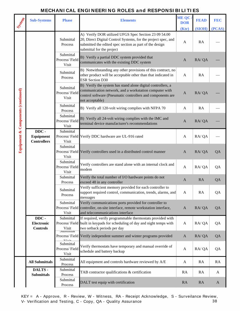
MECHANICAL ENGINEERING ROLES and RESPONSIBILITIES
Sub-Systems Phase Elements ME QC / DOR FEAD FEC
(Ktr) (SIOH) (PCAS)Syste
m
Submittal Process
A) Verify DOR utilized UFGS Spec Section 23 09 54.00 20, Direct Digital Control Systems, for the project spec, and submitted the edited spec section as part of the design submittal for the project
A RA —
Submittal Process/ Field
Visit
B) Verify a partial DDC system provided that communicates with the existing DDC system A RA/ QA —
Submittal Process
B) Notwithstanding any other provisions of this contract, no other product will be acceptable other than that indicated in ESR Section D30
A RA —
Submittal Process/ Field
Visit
B) Verify the system has stand alone digital controllers, a communication network, and a workstation computer with control software (Pneumatic controllers and components are not acceptable)
A RA/ QA —
Submittal Process B) Verify all 120-volt wiring complies with NFPA 70 A RA —
Submittal Process/ Field
Visit
B) Verify all 24-volt wiring complies with the IMC and terminal device manufacturer's recommendations A RA/ QA —
DDC - Equipment Controllers
Submittal Process/ Field
VisitVerify DDC hardware are UL-916 rated A RA/ QA —
Submittal Process/ Field
VisitVerify controllers used in a distributed control manner A RA/ QA QA
Submittal Process/ Field
Visit
Verify controllers are stand alone with an internal clock and modem A RA/ QA QA
Submittal Process
Verify the total number of I/O hardware points do not exceed 48 in any controller A RA QA
Submittal Process
Verify sufficient memory provided for each controller to support required control, communication, trends, alarms, and messages
A RA QA
Submittal Process/ Field
Visit
Verify communications ports provided for controller to controller, on-site interface, remote workstation interface, and telecommunications interface
A RA/ QA QA
DDC - Electronic Controls
Submittal Process/ Field
Visit
If required, verify programmable thermostats provided with built in keypads for scheduling of day and night temps with two setback periods per day
A RA/ QA QA
Submittal Process/ Field
VisitVerify independent summer and winter programs provided A RA/ QA QA
Submittal Process/ Field
Visit
Verify thermostats have temporary and manual override of schedule and battery backup A RA/ QA QA
All Submittals Submittal Process All equipment and controls hardware reviewed by A/E A RA RA
DALTS - Submittals
Submittal Process TAB contractor qualifications & certification RA RA A
Submittal Process DALT test equip with certification RA RA A
Equ
ipm
ent &
Com
pone
nts (
cont
inue
d)
KEY = A - Approve, R - Review, W - Witness, RA - Receipt Acknowledge, S - Surveilance Review, V- Verification and Testing, C - Copy, QA - Quality Assurance 38

MECHANICAL ENGINEERING ROLES and RESPONSIBILITIES
Sub-Systems Phase Elements ME QC / DOR FEAD FEC
(Ktr) (SIOH) (PCAS)Syste
m
Submittal ProcesDALT test plan RA RA A
Submittal ProcesDALT tests report including plan drawing of duct to be tested and square foot calc for each section RA RA A
DALTS - Testing
Submittal Process Ductwork to be DALT'd RA RA A
Field Visit Testing V W WSubmittal ProcesPre-final DALT report RA C ASubmittal ProcesCertified final DALT report RA C A
DALTS - Acceptance
TestingField Visit Quality assurance - Contracting officer DALT field checks V W W
Field Visit Additional field checks V W WTABS -
SubmittalsSubmittal Process TAB contractors qualifications & certification RA RA A
Submittal Process Pre-TAB engineering report RA RA A
Submittal Process *Discussion on TAB procedure RA RA A
Submittal Process *Pre-requisite checklist RA RA A
Submittal Process *Design review report RA RA A
Submittal Process *Preliminary TAB test report RA RA A
Submittal Process Certified TAB test report (Season 1) RA RA A
Submittal Process Certified TAB test report (Season 2 (coil data)) RA RA A
TABS - Pre-Test Checklist
1) Variable Air Volume Series Boxes
a) GeneralField Visit Louvers installed V W —Field Visit Manual dampers open and locked V W —Field Visit Automatic dampers set properly V W —Field Visit Housing construction leakage V W —Field Visit Access doors per plans & specs. V W —Field Visit Condensate drain piping & pan V W —Field Visit Free from dirt & debris V W —Field Visit Nameplate data clearly visible V W —
b) FiltersField Visit Type / size / number correct V W —Field Visit Clean V W —Field Visit Blank-off plates installed V W —Field Visit Frame leakage at a minimum V W —
c) Coils (Hydronic – Water / Steam)Field Visit Size & rows V W —Field Visit Fin spacing & condition V W —Field Visit Obstructions and/or debris V W —Field Visit Correct air flow direction V W —Field Visit Correct piping connections / flow V W —
KEY = A - Approve, R - Review, W - Witness, RA - Receipt Acknowledge, S - Surveilance Review, V- Verification and Testing, C - Copy, QA - Quality Assurance 39
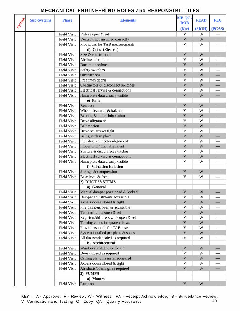
MECHANICAL ENGINEERING ROLES and RESPONSIBILITIES
Sub-Systems Phase Elements ME QC / DOR FEAD FEC
(Ktr) (SIOH) (PCAS)Syste
m
Field Visit Valves open & set V W —Field Visit Vents / traps installed correctly V W —Field Visit Provisions for TAB measurements V W —
d) Coils (Electric)Field Visit Size & construction V W —Field Visit Airflow direction V W —Field Visit Duct connections V W —Field Visit Safety switches V W —Field Visit Obstructions V W —Field Visit Free from debris V W —Field Visit Contractors & disconnect switches V W —Field Visit Electrical service & connections V W —Field Visit Nameplate data clearly visible V W —
e) FansField Visit Rotation V W —Field Visit Wheel clearance & balance V W —Field Visit Bearing & motor lubrication V W —Field Visit Drive alignment V W —Field Visit Belt tension V W —Field Visit Drive set screws tight V W —Field Visit Belt guards in place V W —Field Visit Flex duct connector alignment V W —Field Visit Proper unit / duct alignment V W —Field Visit Starters & disconnect switches V W —Field Visit Electrical service & connections V W —Field Visit Nameplate data clearly visible V W —
f) Vibration isolationField Visit Springs & compression V W —Field Visit Base level & free V W —
2) DUCT SYSTEMS a) General
Field Visit Manual damper positioned & locked V W —Field Visit Damper adjustments accessible V W —Field Visit Access doors closed & tight V W —Field Visit Fire dampers open & accessible V W —Field Visit Terminal units open & set V W —Field Visit Registers/diffusers wide open & set V W —Field Visit Turning vanes in square elbows V W —Field Visit Provisions made for TAB tests V W —Field Visit System installed per plans & specs. V W —Field Visit All ductwork sealed as required V W —
b) ArchitecturalField Visit Windows installed & closed V W —Field Visit Doors closed as required V W —Field Visit Ceiling plenums installed/sealed V W —Field Visit Access doors closed & tight V W —Field Visit Air shafts/openings as required V W —
3) PUMPS a) Motors
Field Visit Rotation V W —
KEY = A - Approve, R - Review, W - Witness, RA - Receipt Acknowledge, S - Surveilance Review, V- Verification and Testing, C - Copy, QA - Quality Assurance 40

MECHANICAL ENGINEERING ROLES and RESPONSIBILITIES
Sub-Systems Phase Elements ME QC / DOR FEAD FEC
(Ktr) (SIOH) (PCAS)Syste
m
Field Visit Lubrication V W —Field Visit Alignment V W —Field Visit Set screws tight V W —Field Visit Guards in place V W —Field Visit Tank level and controls V W —Field Visit Starters & disconnects V W —Field Visit Electrical service & connections V W —
b) PipingField Visit Correct flow V W —Field Visit Correct connections V W —Field Visit Leakage V W —Field Visit Valves positioned & set V W —Field Visit Strainers clean V W —Field Visit Air Vented V W —Field Visit Flexible connectors installed V W —Field Visit Provisions made for TAB tests V W —Field Visit System water clean V W —
c) BasesField Visit Vibration isolation V W —Field Visit Grouting (if required) V W —Field Visit Leveling V W —
4) HYDRONIC EQUIPMENT a) Boilers
Field Visit Operating controls & devices V W —Field Visit Safety controls & devices V W —Field Visit Lubrication of fans & pumps V W —Field Visit Draft controls & devices V W —Field Visit Piping controls & devices V W —Field Visit Valves set & open V W —Field Visit Water make-up provisions V W —Field Visit Blowdown provisions V W —Field Visit Electrical connections V W —Field Visit Nameplate data clearly visible V W —
b) Heat ExchangersField Visit Correct flow & connections V W —Field Visit Valves open or set V W —Field Visit Air vents or steam traps V W —Field Visit Leakage V W —Field Visit Provisions made for TAB tests V W —Field Visit Nameplate data clearly visible V W —
c) Cooling Towers/Evaporative CondensersField Visit Correct flow & connections V W —Field Visit Valves open or set V W —Field Visit Leakage V W —Field Visit Provisions made for TAB tests V W —Field Visit Sump water level V W —Field Visit Spray nozzles V W —Field Visit Fan/Pump rotation V W —Field Visit Motor/Fan lubrication V W —Field Visit Drives & alignment V W —
Syst
em A
ccep
tanc
e (c
ontin
ued)
KEY = A - Approve, R - Review, W - Witness, RA - Receipt Acknowledge, S - Surveilance Review, V- Verification and Testing, C - Copy, QA - Quality Assurance 41

MECHANICAL ENGINEERING ROLES and RESPONSIBILITIES
Sub-Systems Phase Elements ME QC / DOR FEAD FEC
(Ktr) (SIOH) (PCAS)Syste
m
Field Visit Guards in place V W —Field Visit Starters & disconnects V W —Field Visit Electrical connections V W —Field Visit Nameplate data clearly visible V W —
5) REFRIGERANT EQUIPMENTField Visit Crankcase heaters energized V W —Field Visit Operating controls & devices V W —Field Visit Safety controls & devices V W —Field Visit Valves open V W —Field Visit Piping connections & flow V W —Field Visit Flexible connectors V W —Field Visit Oil level & lubrication V W —Field Visit Alignment & drives V W —Field Visit Guards in place V W —Field Visit Vibration isolation V W —Field Visit Starters/Contactors/Disconnects V W —Field Visit Electrical connections V W —Field Visit Nameplate data clearly visible V W —
6) HYDRONIC PIPING SYSTEMField Visit Leak tested V W —Field Visit Fluid levels & make-up V W —Field Visit Relief or safety valves V W —Field Visit Expansion tanks & air vents V W —Field Visit Steam traps & connections V W —Field Visit Strainers clean V W —Field Visit Valves open & set V W —Field Visit Provisions made for TAB tests V W —Field Visit Systems installed per plans & specs. V W —
7) CONTROLS & CONTROL SYSTEMSField Visit Data centers V W —Field Visit Outdoor/return Air/reset V W —Field Visit Economizer set & tested V W —Field Visit AHU Static pressure set V W —Field Visit Room controls calibrated V W —Field Visit VAV box regulators set to design V W —Field Visit VAV box P.E. switches set V W —Field Visit Proper end-of-line static pressure V W —Field Visit VAV box reheats tested V W —
8) OTHER CHECKSSubmittal Process
Appropriate contractors notified of TABSA RA S
Submittal Process
Preliminary data completeA RA S
Submittal Process
Test report forms preparedS RA A
Syst
em A
ccep
tanc
e (c
ontin
ued)
KEY = A - Approve, R - Review, W - Witness, RA - Receipt Acknowledge, S - Surveilance Review, V- Verification and Testing, C - Copy, QA - Quality Assurance 42

MECHANICAL ENGINEERING ROLES and RESPONSIBILITIES
Sub-Systems Phase Elements ME QC / DOR FEAD FEC
(Ktr) (SIOH) (PCAS)Syste
m
TABS - Testing Field Visit TAB field work V WSubmittal Process Preliminary procedures RA C A
Field Visit TAB air distrbution systems V W —Field Visit TAB water distribution systems V W —Field Visit Sound measurement work V W —
Field Visit TAB work on performance tests without seasonal limitations V W —
Field Visit TAB work on performance tests with seasonal limitations V W —
Field Visit Marking settings V W —Field Visit Marking of test ports V W —
TABS - Acceptance
TestingField Visit Quality assurance - Contracting officer TAB field checks V W W
Field Visit Additional field checks V W WACATS -
SubmittalsSubmittal Process Controls contractor qualifications RA RA A
Submittal Process Manufacturers field report RA RA A
Submittal Process Performance verification test plan (PVT) RA RA A
Submittal Process Pre-PVT checklist RA RA A
Submittal Process
Final certified PVT report (with all mods incorporated in as-builts) RA RA A
ACATS - Pre-PVT Checklist Field Visit
Prior to conducting the PVT, thoroughly inspect the installed work with the Contractor's QC representative and the mechanical contractor using the following checklist. Submit the checklist with items checked off once verified. Provide a detailed explana
V W —
Field Visit a. Verify all required mechanical installation work is successfully completed, and all HVAC equipment is workingcorrectly (or will be by the time the PVT is conducted).
V W —
Field Visit b. Verify HVAC motors operate below full-load amperage ratings.
V W —
Field Visit c. Verify all required control system components, wiring, and accessories are installed.
V W —
Field Visit d. Verify the installed control system architecture matches approved drawings.
V W —
Field Visit e. Verify all control circuits operate at the proper voltage and are free from grounds or faults.
V W —
Field Visit f. Verify all required surge protection is installed and functions correctly.
V W —
Field Visit g. Verify the A/C Power Table specified in "CONTROLS SYSTEM OPERATORS MANUALS" is accurate.
V W —
KEY = A - Approve, R - Review, W - Witness, RA - Receipt Acknowledge, S - Surveilance Review, V- Verification and Testing, C - Copy, QA - Quality Assurance 43

MECHANICAL ENGINEERING ROLES and RESPONSIBILITIES
Sub-Systems Phase Elements ME QC / DOR FEAD FEC
(Ktr) (SIOH) (PCAS)Syste
m
Field Visith. Verify all DDC network communications function properly, including uploading and downloading programming changes.
V W —
Field Visiti. Using the BACnet protocol analyzer (if provided or required in this specification), verify communications are error free.
V W —
Field Visit j. Verify each digital controller’s programming is backed up.
V W —
Field Visit k. Verify all wiring, components, and panels are properly labeled.
V W —
Field Visitl. Verify all required points are programmed into devices.
V W —
Field Visit m. Verify all TAB work affecting controls is complete. V W —
Field Visit n. Verify all valve and actuator zero and span adjustments are set properly.
V W —
Field Visito. Verify all sensor readings are accurate and calibrated.
V W —
Field Visit p. Verify each control valve and actuator goes to normal position upon loss of power.
V W —
Field Visit q. Verify all control loops are tuned for smooth and stable operation. View trend data where applicable.
V W —
Field Visit r. Verify each controller works properly in stand-alone mode.
V W —
Field Visit s. Verify all safety controls and devices function properly, including interfaces with building fire alarm systems.
V W —
Field Visit t. Verify all electrical interlocks work properly. V W —
Field Visit
u. Verify all workstations, notebooks and maintenance personnel interface tools are delivered, all system and database software is installed, and graphic pages are created for each workstation and notebook. Notify the Government when phone lines or netw
V W —
Field Visitv. Verify the as-built (shop) control drawings are completed. V W —
ACATS - Testing Field Visit Field testing of components V W —
Field Visit Field testing of programming V W —Field Visit Pre-performance verification testing V W —
ACATS - Acceptance
TestingField Visit Performance verification testing V W W
Field Visit Performance verification re-resting V W W
Syst
em A
ccep
tanc
e (c
ontin
ued)
KEY = A - Approve, R - Review, W - Witness, RA - Receipt Acknowledge, S - Surveilance Review, V- Verification and Testing, C - Copy, QA - Quality Assurance 44

ROOFING ROLES and RESPONSIBILITIES
Sub-Systems Phase Elements Roof QC / DOR FEAD FEC
(Ktr) (SIOH) (PCAS)Low Sloped
RoofsDesign Guidance Post Award Kick Off Meeting S A
Design Guidance Verify Roof Design Assurance A R S
Submittal Process Review Shop Drawings A S S
Submittal Process Review Manufacturer's Product Data Sheets A S S
Submittal Process Review Design Data ( to include wind and fire resistance) A S S
Submittal Process Review Test Reports A S S
Submittal Process Review Certificates A S S
Submittal Process Review Sample Roof Warranty A S C
Field Visit Conduct Pre Roofing Conference V S SField Visit Review Delivery, Storage, and Handling A S SField Visit Verify Conditions for roof application A S SField Visit Verify Preparation A S SField Visit Verify Application A S SField Visit Verify Protection of Applied Roofing A S SField Visit Verify Field Quality Control A S S
Field Visit Verify Operation Maintenance and Support Information (Roof Warranty and Information Card) A S S
Steep Sloped Roofs
Design Guidance Post Award Kick Off Meeting S A
Design Guidance Verify Roof Design Assurance A R S
Submittal Process Review Shop Drawings A S S
Submittal Process Review Manufacturer's Product Data Sheets A S S
Submittal Process Review Design Data ( to include wind and fire resistance) A S S
Submittal Process Review Test Reports A S S
Submittal Process Review Certificates A S S
Submittal Process Review Sample Roof Warranty A S C
Field Visit Conduct Pre Roofing Conference V S SField Visit Review Delivery, Storage, and Handling A S SField Visit Verify Conditions for roof application A S SField Visit Verify Preparation A S SField Visit Verify Application A S SField Visit Verify Protection of Applied Roofing A S SField Visit Verify Field Quality Control A S S
Field Visit Verify Operation Maintenance and Support Information (Roof Warranty and Information Card) A S S
Syste
mR
oofin
g
KEY = A - Approve, R - Review, W - Witness, RA - Receipt Acknowledge, S - Surveilance Review, V- Verification and Testing, C - Copy, QA - Quality Assurance 45

UNDERWATER STRUCTURES ROLES and RESPONSIBILITIES
Sub-Systems Phase Elements UW QC / DOR FEAD FEC/NF
ESC(Ktr) (SIOH) (PCAS)
Submittal Process Shop Drawings A C S
Submittal Process Manufacturer's Data Sheets A C S
Submittal Process Pile driving records A C S
Submittal Process
Concrete testing: petrographic, chemical, service-life modeling A C S
Submittal Process As-built drawings, 3D AUTOCAD format A C S
Field Visit Validate in-water/underwater structure complies with RFP requirements, e.g., number, location, size, etc. A — W
Field Visit
Inspect in-water prestressed/precast concrete piles or sheetpiles for alignment, spalls, cracks, damages, defects, lifting hoops cut/area patched, exposed steel ties, penetrations, etc.
A — W
Field VisitInspect in-water cast-in-place concrete drilled caissons for alignment, spalls, cracks, damages, defects, concrete quality (hardness), honeycombing, etc.
A — W
Field VisitInspect in-water steel piles and/or p/c p/s concrete sheetpiles for alignment, damage/buckling, coating damage, penetrations, gaps, etc.
A — W
Field Visit Inspect underwater concrete placement for defects such as honeycombing, concrete quality (hardness) A — W
Field Visit
Inspect underwater slope protection for conformance with RFP requirements such as rock/boulder size, placement gap limits, angle, location (e.g., toe of slope protection), consistency, etc.
A — W
Field Visit Inspect underwater Cathodic Protection anodes and connections A — W
Field Visit Inspect for underwater debris, existing or by construction. A — W
Field Visit Validate in-water/underwater structure complies with RFP requirements, e.g., number, location, size, etc. A — W
Field Visit Validate in-water/underwater structure complies with RFP requirements, e.g., number, location, size, etc. A — W
Field Visit Validate in-water/underwater structure complies with RFP requirements, e.g., number, location, size, etc. A — W
Pile Foundations (H101001)Sheet Piles (H101001)Caissons
(H101001)Cofferdams (H101001)Wraps and
Encasements (H101001)Sheet Pile Bulheads
(H101003)Gravity Walls
(H101003)Block Walls (H101003)Seawalls
(H101006)Boat Ramps (H101007)
Cut-Off Walls (H101008)
Wave Attenuation
Walls (H101009)
Fender Piles (H104001)Dolphins
(H104004)
Syste
mW
ater
fron
t Str
uctu
re H
10 (U
nifo
rmat
II) -
Sub
stru
ctur
e H
1010
KEY = A - Approve, R - Review, W - Witness, RA - Receipt Acknowledge, S - Surveilance Review, V- Verification and Testing, C - Copy, QA - Quality Assurance 46

UNDERWATER STRUCTURES ROLES and RESPONSIBILITIES
Sub-Systems Phase Elements UW QC / DOR FEAD FEC/NF
ESC(Ktr) (SIOH) (PCAS)Sy
stem
All Submittal Process Shop Drawings A C S
Submittal Process Manufacturer's Data Sheets A C S
Field Visit Validate in-water/underwater cable complies with RFP requirements, e.g., number, location, size, etc. A — W
Field Visit Inspect underwater cable for defects/damages, kinks, missing anchors, coating damage, etc. A — W
Field Visit Inspect for underwater debris, existing or by construction. A — W
All Submittal Process Shop Drawings A C S
Submittal Process Manufacturer's Data Sheets A C S
Field Visit Validate in-water/underwater component complies with RFP requirements, e.g., number, location, size, etc. A — W
Field Visit Inspect underwater component for defects/damages, cracks, missing anchors, coating damage, etc. A — W
Field Visit Inspect for underwater debris, existing or by construction. A — WUnd
erw
ater
Util
ity P
ipes
an
d C
ondu
itsU
nder
wat
er C
able
s
KEY = A - Approve, R - Review, W - Witness, RA - Receipt Acknowledge, S - Surveilance Review, V- Verification and Testing, C - Copy, QA - Quality Assurance 47

Approve (A)Professional or quality control endorsement of the submittal or installed system meets the contract requirements
Review (R) To confirm accuracy of the submittal and that it meets contract requirements
Witness (W) Observe demonstration of system performance for acceptance
Receipt Acknowledge (RA) Confirm receipt of submittal with no review necessary
Surveillance Review (S) A quality assurance review based on risk, complexity, and workload
Performance Verification and Acceptance Testing (V) A demonstration of satisfactory construction and
system performance
Receive Copy of Correspondence (C) Receive a copy of the transmittal sheet and/or correspondence letter
Quality Assurance Inspection (QA)Witnessing satisfactory performance without testing all devices or visual inspection of various parts of the system
DEFINITIONS